EP3769874A1 - Einsatz und damit versehenes schneidwerkzeug - Google Patents
Einsatz und damit versehenes schneidwerkzeug Download PDFInfo
- Publication number
- EP3769874A1 EP3769874A1 EP19770446.3A EP19770446A EP3769874A1 EP 3769874 A1 EP3769874 A1 EP 3769874A1 EP 19770446 A EP19770446 A EP 19770446A EP 3769874 A1 EP3769874 A1 EP 3769874A1
- Authority
- EP
- European Patent Office
- Prior art keywords
- layer
- base
- insert
- thickness
- insert according
- Prior art date
- Legal status (The legal status is an assumption and is not a legal conclusion. Google has not performed a legal analysis and makes no representation as to the accuracy of the status listed.)
- Pending
Links
Images

Classifications
-
- B—PERFORMING OPERATIONS; TRANSPORTING
- B23—MACHINE TOOLS; METAL-WORKING NOT OTHERWISE PROVIDED FOR
- B23B—TURNING; BORING
- B23B27/00—Tools for turning or boring machines; Tools of a similar kind in general; Accessories therefor
- B23B27/14—Cutting tools of which the bits or tips or cutting inserts are of special material
-
- C—CHEMISTRY; METALLURGY
- C23—COATING METALLIC MATERIAL; COATING MATERIAL WITH METALLIC MATERIAL; CHEMICAL SURFACE TREATMENT; DIFFUSION TREATMENT OF METALLIC MATERIAL; COATING BY VACUUM EVAPORATION, BY SPUTTERING, BY ION IMPLANTATION OR BY CHEMICAL VAPOUR DEPOSITION, IN GENERAL; INHIBITING CORROSION OF METALLIC MATERIAL OR INCRUSTATION IN GENERAL
- C23C—COATING METALLIC MATERIAL; COATING MATERIAL WITH METALLIC MATERIAL; SURFACE TREATMENT OF METALLIC MATERIAL BY DIFFUSION INTO THE SURFACE, BY CHEMICAL CONVERSION OR SUBSTITUTION; COATING BY VACUUM EVAPORATION, BY SPUTTERING, BY ION IMPLANTATION OR BY CHEMICAL VAPOUR DEPOSITION, IN GENERAL
- C23C16/00—Chemical coating by decomposition of gaseous compounds, without leaving reaction products of surface material in the coating, i.e. chemical vapour deposition [CVD] processes
- C23C16/22—Chemical coating by decomposition of gaseous compounds, without leaving reaction products of surface material in the coating, i.e. chemical vapour deposition [CVD] processes characterised by the deposition of inorganic material, other than metallic material
- C23C16/30—Deposition of compounds, mixtures or solid solutions, e.g. borides, carbides, nitrides
- C23C16/34—Nitrides
-
- C—CHEMISTRY; METALLURGY
- C22—METALLURGY; FERROUS OR NON-FERROUS ALLOYS; TREATMENT OF ALLOYS OR NON-FERROUS METALS
- C22C—ALLOYS
- C22C29/00—Alloys based on carbides, oxides, nitrides, borides, or silicides, e.g. cermets, or other metal compounds, e.g. oxynitrides, sulfides
- C22C29/005—Alloys based on carbides, oxides, nitrides, borides, or silicides, e.g. cermets, or other metal compounds, e.g. oxynitrides, sulfides comprising a particular metallic binder
-
- C—CHEMISTRY; METALLURGY
- C22—METALLURGY; FERROUS OR NON-FERROUS ALLOYS; TREATMENT OF ALLOYS OR NON-FERROUS METALS
- C22C—ALLOYS
- C22C29/00—Alloys based on carbides, oxides, nitrides, borides, or silicides, e.g. cermets, or other metal compounds, e.g. oxynitrides, sulfides
- C22C29/02—Alloys based on carbides, oxides, nitrides, borides, or silicides, e.g. cermets, or other metal compounds, e.g. oxynitrides, sulfides based on carbides or carbonitrides
-
- C—CHEMISTRY; METALLURGY
- C22—METALLURGY; FERROUS OR NON-FERROUS ALLOYS; TREATMENT OF ALLOYS OR NON-FERROUS METALS
- C22C—ALLOYS
- C22C29/00—Alloys based on carbides, oxides, nitrides, borides, or silicides, e.g. cermets, or other metal compounds, e.g. oxynitrides, sulfides
- C22C29/02—Alloys based on carbides, oxides, nitrides, borides, or silicides, e.g. cermets, or other metal compounds, e.g. oxynitrides, sulfides based on carbides or carbonitrides
- C22C29/04—Alloys based on carbides, oxides, nitrides, borides, or silicides, e.g. cermets, or other metal compounds, e.g. oxynitrides, sulfides based on carbides or carbonitrides based on carbonitrides
-
- C—CHEMISTRY; METALLURGY
- C23—COATING METALLIC MATERIAL; COATING MATERIAL WITH METALLIC MATERIAL; CHEMICAL SURFACE TREATMENT; DIFFUSION TREATMENT OF METALLIC MATERIAL; COATING BY VACUUM EVAPORATION, BY SPUTTERING, BY ION IMPLANTATION OR BY CHEMICAL VAPOUR DEPOSITION, IN GENERAL; INHIBITING CORROSION OF METALLIC MATERIAL OR INCRUSTATION IN GENERAL
- C23C—COATING METALLIC MATERIAL; COATING MATERIAL WITH METALLIC MATERIAL; SURFACE TREATMENT OF METALLIC MATERIAL BY DIFFUSION INTO THE SURFACE, BY CHEMICAL CONVERSION OR SUBSTITUTION; COATING BY VACUUM EVAPORATION, BY SPUTTERING, BY ION IMPLANTATION OR BY CHEMICAL VAPOUR DEPOSITION, IN GENERAL
- C23C16/00—Chemical coating by decomposition of gaseous compounds, without leaving reaction products of surface material in the coating, i.e. chemical vapour deposition [CVD] processes
- C23C16/22—Chemical coating by decomposition of gaseous compounds, without leaving reaction products of surface material in the coating, i.e. chemical vapour deposition [CVD] processes characterised by the deposition of inorganic material, other than metallic material
- C23C16/30—Deposition of compounds, mixtures or solid solutions, e.g. borides, carbides, nitrides
- C23C16/36—Carbonitrides
-
- C—CHEMISTRY; METALLURGY
- C23—COATING METALLIC MATERIAL; COATING MATERIAL WITH METALLIC MATERIAL; CHEMICAL SURFACE TREATMENT; DIFFUSION TREATMENT OF METALLIC MATERIAL; COATING BY VACUUM EVAPORATION, BY SPUTTERING, BY ION IMPLANTATION OR BY CHEMICAL VAPOUR DEPOSITION, IN GENERAL; INHIBITING CORROSION OF METALLIC MATERIAL OR INCRUSTATION IN GENERAL
- C23C—COATING METALLIC MATERIAL; COATING MATERIAL WITH METALLIC MATERIAL; SURFACE TREATMENT OF METALLIC MATERIAL BY DIFFUSION INTO THE SURFACE, BY CHEMICAL CONVERSION OR SUBSTITUTION; COATING BY VACUUM EVAPORATION, BY SPUTTERING, BY ION IMPLANTATION OR BY CHEMICAL VAPOUR DEPOSITION, IN GENERAL
- C23C16/00—Chemical coating by decomposition of gaseous compounds, without leaving reaction products of surface material in the coating, i.e. chemical vapour deposition [CVD] processes
- C23C16/22—Chemical coating by decomposition of gaseous compounds, without leaving reaction products of surface material in the coating, i.e. chemical vapour deposition [CVD] processes characterised by the deposition of inorganic material, other than metallic material
- C23C16/30—Deposition of compounds, mixtures or solid solutions, e.g. borides, carbides, nitrides
- C23C16/40—Oxides
-
- C—CHEMISTRY; METALLURGY
- C23—COATING METALLIC MATERIAL; COATING MATERIAL WITH METALLIC MATERIAL; CHEMICAL SURFACE TREATMENT; DIFFUSION TREATMENT OF METALLIC MATERIAL; COATING BY VACUUM EVAPORATION, BY SPUTTERING, BY ION IMPLANTATION OR BY CHEMICAL VAPOUR DEPOSITION, IN GENERAL; INHIBITING CORROSION OF METALLIC MATERIAL OR INCRUSTATION IN GENERAL
- C23C—COATING METALLIC MATERIAL; COATING MATERIAL WITH METALLIC MATERIAL; SURFACE TREATMENT OF METALLIC MATERIAL BY DIFFUSION INTO THE SURFACE, BY CHEMICAL CONVERSION OR SUBSTITUTION; COATING BY VACUUM EVAPORATION, BY SPUTTERING, BY ION IMPLANTATION OR BY CHEMICAL VAPOUR DEPOSITION, IN GENERAL
- C23C16/00—Chemical coating by decomposition of gaseous compounds, without leaving reaction products of surface material in the coating, i.e. chemical vapour deposition [CVD] processes
- C23C16/22—Chemical coating by decomposition of gaseous compounds, without leaving reaction products of surface material in the coating, i.e. chemical vapour deposition [CVD] processes characterised by the deposition of inorganic material, other than metallic material
- C23C16/30—Deposition of compounds, mixtures or solid solutions, e.g. borides, carbides, nitrides
- C23C16/40—Oxides
- C23C16/403—Oxides of aluminium, magnesium or beryllium
-
- C—CHEMISTRY; METALLURGY
- C23—COATING METALLIC MATERIAL; COATING MATERIAL WITH METALLIC MATERIAL; CHEMICAL SURFACE TREATMENT; DIFFUSION TREATMENT OF METALLIC MATERIAL; COATING BY VACUUM EVAPORATION, BY SPUTTERING, BY ION IMPLANTATION OR BY CHEMICAL VAPOUR DEPOSITION, IN GENERAL; INHIBITING CORROSION OF METALLIC MATERIAL OR INCRUSTATION IN GENERAL
- C23C—COATING METALLIC MATERIAL; COATING MATERIAL WITH METALLIC MATERIAL; SURFACE TREATMENT OF METALLIC MATERIAL BY DIFFUSION INTO THE SURFACE, BY CHEMICAL CONVERSION OR SUBSTITUTION; COATING BY VACUUM EVAPORATION, BY SPUTTERING, BY ION IMPLANTATION OR BY CHEMICAL VAPOUR DEPOSITION, IN GENERAL
- C23C28/00—Coating for obtaining at least two superposed coatings either by methods not provided for in a single one of groups C23C2/00 - C23C26/00 or by combinations of methods provided for in subclasses C23C and C25C or C25D
- C23C28/04—Coating for obtaining at least two superposed coatings either by methods not provided for in a single one of groups C23C2/00 - C23C26/00 or by combinations of methods provided for in subclasses C23C and C25C or C25D only coatings of inorganic non-metallic material
- C23C28/042—Coating for obtaining at least two superposed coatings either by methods not provided for in a single one of groups C23C2/00 - C23C26/00 or by combinations of methods provided for in subclasses C23C and C25C or C25D only coatings of inorganic non-metallic material including a refractory ceramic layer, e.g. refractory metal oxides, ZrO2, rare earth oxides
-
- C—CHEMISTRY; METALLURGY
- C23—COATING METALLIC MATERIAL; COATING MATERIAL WITH METALLIC MATERIAL; CHEMICAL SURFACE TREATMENT; DIFFUSION TREATMENT OF METALLIC MATERIAL; COATING BY VACUUM EVAPORATION, BY SPUTTERING, BY ION IMPLANTATION OR BY CHEMICAL VAPOUR DEPOSITION, IN GENERAL; INHIBITING CORROSION OF METALLIC MATERIAL OR INCRUSTATION IN GENERAL
- C23C—COATING METALLIC MATERIAL; COATING MATERIAL WITH METALLIC MATERIAL; SURFACE TREATMENT OF METALLIC MATERIAL BY DIFFUSION INTO THE SURFACE, BY CHEMICAL CONVERSION OR SUBSTITUTION; COATING BY VACUUM EVAPORATION, BY SPUTTERING, BY ION IMPLANTATION OR BY CHEMICAL VAPOUR DEPOSITION, IN GENERAL
- C23C28/00—Coating for obtaining at least two superposed coatings either by methods not provided for in a single one of groups C23C2/00 - C23C26/00 or by combinations of methods provided for in subclasses C23C and C25C or C25D
- C23C28/04—Coating for obtaining at least two superposed coatings either by methods not provided for in a single one of groups C23C2/00 - C23C26/00 or by combinations of methods provided for in subclasses C23C and C25C or C25D only coatings of inorganic non-metallic material
- C23C28/044—Coating for obtaining at least two superposed coatings either by methods not provided for in a single one of groups C23C2/00 - C23C26/00 or by combinations of methods provided for in subclasses C23C and C25C or C25D only coatings of inorganic non-metallic material coatings specially adapted for cutting tools or wear applications
-
- C—CHEMISTRY; METALLURGY
- C23—COATING METALLIC MATERIAL; COATING MATERIAL WITH METALLIC MATERIAL; CHEMICAL SURFACE TREATMENT; DIFFUSION TREATMENT OF METALLIC MATERIAL; COATING BY VACUUM EVAPORATION, BY SPUTTERING, BY ION IMPLANTATION OR BY CHEMICAL VAPOUR DEPOSITION, IN GENERAL; INHIBITING CORROSION OF METALLIC MATERIAL OR INCRUSTATION IN GENERAL
- C23C—COATING METALLIC MATERIAL; COATING MATERIAL WITH METALLIC MATERIAL; SURFACE TREATMENT OF METALLIC MATERIAL BY DIFFUSION INTO THE SURFACE, BY CHEMICAL CONVERSION OR SUBSTITUTION; COATING BY VACUUM EVAPORATION, BY SPUTTERING, BY ION IMPLANTATION OR BY CHEMICAL VAPOUR DEPOSITION, IN GENERAL
- C23C30/00—Coating with metallic material characterised only by the composition of the metallic material, i.e. not characterised by the coating process
- C23C30/005—Coating with metallic material characterised only by the composition of the metallic material, i.e. not characterised by the coating process on hard metal substrates
-
- B—PERFORMING OPERATIONS; TRANSPORTING
- B22—CASTING; POWDER METALLURGY
- B22F—WORKING METALLIC POWDER; MANUFACTURE OF ARTICLES FROM METALLIC POWDER; MAKING METALLIC POWDER; APPARATUS OR DEVICES SPECIALLY ADAPTED FOR METALLIC POWDER
- B22F3/00—Manufacture of workpieces or articles from metallic powder characterised by the manner of compacting or sintering; Apparatus specially adapted therefor ; Presses and furnaces
- B22F3/24—After-treatment of workpieces or articles
- B22F2003/241—Chemical after-treatment on the surface
- B22F2003/242—Coating
-
- B—PERFORMING OPERATIONS; TRANSPORTING
- B22—CASTING; POWDER METALLURGY
- B22F—WORKING METALLIC POWDER; MANUFACTURE OF ARTICLES FROM METALLIC POWDER; MAKING METALLIC POWDER; APPARATUS OR DEVICES SPECIALLY ADAPTED FOR METALLIC POWDER
- B22F5/00—Manufacture of workpieces or articles from metallic powder characterised by the special shape of the product
- B22F2005/001—Cutting tools, earth boring or grinding tool other than table ware
-
- B—PERFORMING OPERATIONS; TRANSPORTING
- B22—CASTING; POWDER METALLURGY
- B22F—WORKING METALLIC POWDER; MANUFACTURE OF ARTICLES FROM METALLIC POWDER; MAKING METALLIC POWDER; APPARATUS OR DEVICES SPECIALLY ADAPTED FOR METALLIC POWDER
- B22F2998/00—Supplementary information concerning processes or compositions relating to powder metallurgy
- B22F2998/10—Processes characterised by the sequence of their steps
-
- B—PERFORMING OPERATIONS; TRANSPORTING
- B23—MACHINE TOOLS; METAL-WORKING NOT OTHERWISE PROVIDED FOR
- B23B—TURNING; BORING
- B23B2228/00—Properties of materials of tools or workpieces, materials of tools or workpieces applied in a specific manner
- B23B2228/10—Coatings
- B23B2228/105—Coatings with specified thickness
Definitions
- the present disclosure relates to an insert for use in a cutting process and a cutting tool including the same.
- Cermets including titanium (Ti) as a main component are now widely used as bases of members requiring wear resistance, sliding property, and fracture resistance, such as cutting tools, wear-resistant members, and sliding members.
- Patent Literature 1 discloses a surface-coated titanium carbonitride-based cermet cutting tool, in which 12 to 20% of a binder phase component based on cobalt (Co) and nickel (Ni) is contained, an erosion alloy phase composed of a metal binder phase component is formed on a surface portion, and a TiN layer having a diffusion-preventing effect is additionally provided thereon to suppress fracture or chipping.
- Patent Literature 1 Japanese Patent No. 5989930
- An insert of the present disclosure includes a base and a coating layer covering a surface of the base.
- the base includes a hard phase containing a carbonitride including Ti and a binder phase containing Co.
- the coating layer includes a first layer including a plurality of TiN particles at a position in contact with the base. In a cross section vertical to a surface of the base, the width of the TiN particles in a direction parallel to the surface of the base is 35 nm or less.
- a cutting tool of the present disclosure includes a holder extending from a first end to a second end and having a pocket on the first end side, and the insert positioned in the pocket positioned in pocket.
- an insert 1 of the present disclosure includes a base 3.
- the base 3 includes a hard phase (not illustrated) of a carbonitride including Ti, and a binder phase (not illustrated) containing Co.
- the base 3 is a cermet.
- examples of the cermet include, but are not limited to, compounds containing TiC or TiN, etc. in addition to TiCN.
- the insert 1 of the present disclosure includes a coating layer 5 covering at least a part of the base 3.
- the coating layer 5 may be formed, for example, by a CVD process.
- the coating layer 5 includes a first layer 5a containing a plurality of TiN particles at a position in contact with the base 3.
- the insert 1 may further include a second layer 5b containing TiCN particles on the first layer 5a.
- the insert 1 may include a third layer 5c containing Al 2 O 3 particles on the second layer 5b.
- the first layer 5a has a plurality of TiN particles.
- the width of TiN particles in a direction parallel to the surface of the base 3 (hereinafter also referred to as the width of TiN particles) is 35 nm or less.
- the width of TiN particles may be measured at a position 0.05 ⁇ m from the surface of the base 3. When the thickness of the first layer 5a is 0.05 ⁇ m or less, the width of TiN particles may be measured at a position half the thickness of the first layer 5a.
- the width of TiN particles is the mean value of the widths of a plurality of TiN particles measured at the position described above.
- the ratio (which hereinafter may be referred to as aspect ratio) of the height of TiN particles in a direction vertical to the surface of the base 3 to the width of TiN particles in the direction parallel to the surface of the base 3 may be 1.0 to 1.7. With such a configuration, the adhesion force between the first layer 5a and the base 3 is excellent.
- the aspect ratio of TiN particles is measured from TiN particles present up to 0.05 ⁇ m from the surface of the base 3.
- the thickness of the first layer 5a may be 0.1 to 1.0 ⁇ m.
- the thickness of the first layer 5a is 0.1 ⁇ m or more, diffusion of the binder phase component included in the base 3 to the coating is suppressed, and the fracture resistance is excellent.
- the thickness of the first layer 5a is 1.0 ⁇ m or less, the TiCN particles included in the upper layer, that is, the second layer 5b are finer, and the wear resistance is excellent.
- the thickness of the first layer 5a may be 0.3 to 0.7 ⁇ m.
- the TiN particles included in the first layer 5a are not necessarily composed of pure TiN.
- C and/or O may be contained.
- the Ti or N content may be larger than the other components.
- the second layer 5b including a plurality of TiCN particles and the third layer 5c including Al 2 O 3 particles may be disposed in this order on the first layer 5a.
- the insert 1 of the present disclosure has, for example, a quadrangular plate shape, and its upper surface in FIG. 1 is a rake face.
- the insert 1 has a lower surface on the side opposite to the upper surface and a side surface between the upper surface and the lower surface to connect to each of the upper and lower surfaces. At least a part of the side surface is a flank face.
- the insert 1 of the present disclosure has a cutting edge 7 positioned at at least a part of a ridge line where the upper surface and the side surface meet.
- the insert 1 has the cutting edge 7 positioned at at least a part of a ridge line where the rake face and the flank face meet.
- the insert 1 In the insert 1, the entire outer perimeter of the rake face may serve as the cutting edge 7.
- the insert 1 is not limited to such a configuration and, for example, may have the cutting edge 7 at only one side, or partially, of the quadrangular rake face.
- the size of the insert 1 is not limited and, for example, the length of one side of the rake face is set to about 3 to 20 mm.
- the thickness of the insert 1 is set, for example, to about 1 to 20 mm.
- the binder phase may take up 5 to 25 area% in a cross section of the base 3.
- the binder phase may be composed of Co and W only, except inevitable impurities.
- each element content may be 0.5 mass% or less.
- the base 3 in the insert 1 of the present disclosure may contain Co 0.93 W 0.07 .
- the insert 1 excellent in wear resistance and fracture resistance thus can be obtained.
- Co 0.93 W 0.07 is a crystal represented in PDF:01-071-7509 of the JCPDS card.
- the proportion of Co 0.93 W 0.07 in all the crystals may be 5 to 10 in a crystalline phase analysis by X-ray diffraction.
- the proportion of Co 0.93 W 0.07 may be 8 to 10.
- the proportion of Co 0.93 W 0.07 above is obtained by calculating the proportion of Co 0.93 W 0.07 in the proportions of all the crystals detected by Rietveld refinement using an X ray system manufactured by PANalytical, X'Pert Pro 2 ⁇ : 10 to 100, and analysis software RIETAN-FP.
- the second layer 5b includes TiCN particles that are TiCN crystals.
- the thermal expansion coefficient of the TiCN crystals is about 8 ⁇ 10 -6 /°C, and when the thermal expansion coefficient of the base 3 is 9.0 ⁇ 10 -6 /°C or higher, the thermal expansion coefficient of the third layer 5b is smaller than the thermal expansion coefficient of the base 3.
- the second layer 5b is interposed between the base 3 and the third layer 5c to suppress peeling of the third layer 5c and suppress abrasive wear.
- the third layer 5c is positioned on the second layer 5b.
- the third layer 5c includes Al 2 O 3 particles that are Al 2 O 3 crystals.
- the thermal expansion coefficient of the Al 2 O 3 crystals is about 7.2 ⁇ 10 -6 /°C and is smaller than the thermal expansion coefficients of the base 3 and the second layer 5b.
- the second layer 5b and the third layer 5c may be in direct contact or, for example, a TiN layer (not illustrated) may be positioned between them.
- an adequate compressive stress can be exerted on the second layer 5b and the third layer 5c by adjusting the thermal expansion coefficient of the base 3 and the thickness of the third layer 5c.
- the thickness of the third layer 5c is 2 ⁇ m or more.
- the compressive stress exerted on the second layer 5b may be 250 to 500 MPa
- the compressive stress exerted on the third layer 5c may be 450 MPa or more
- the value of the compressive stress exerted on the third layer 5c may be larger than the compressive stress exerted on the second layer 5b.
- the insert 1 having such a configuration is excellent in wear resistance and durability.
- the compressive stresses exerted on the second layer 5b and the third layer 5c may be determined based on measurement using a 2D process. Specifically, a section of the flank face, 1 mm or more away from the cutting edge 7, is set as a measurement location, and X-ray diffraction peaks are measured. For the crystal structure specified from the measurement result, the compressive stress can be obtained by determining how the value of 2 ⁇ in the measurement result deviates from the value of 2 ⁇ serving as a standard described in the JCPDS card.
- the residual stress When a residual stress has a negative value, the residual stress is compressive stress. When the value of compressive stress is expressed, it is represented by an absolute value with no minus sign.
- the third layer 5c is at a position more distant from the base 3.
- the third layer 5c comes into contact with the workpiece before the second layer 5b.
- the third layer 5c includes Al 2 O 3 particles and has a thickness of 2 ⁇ m or more, the wear resistance and the oxidation resistance are high.
- the thickness of the third layer 5c is 2.5 ⁇ m or more and 8.0 ⁇ m or less, the wear resistance and the oxidation resistance are more excellent.
- the sum of the thickness of the second layer 5b and the thickness of the third layer 5c may be 7 ⁇ m or more and 18 ⁇ m or less.
- the sum of the thicknesses may be 8 ⁇ m or more and 16 ⁇ m or less.
- the second layer 5b may have a thickness of 5 ⁇ m or more and 10 ⁇ m or less. With such a range, the wear resistance and the fracture resistance of the insert 1 are excellent.
- the thickness of the third layer 5c may be 0.2 to 0.4 times the sum of the thickness of the second layer 5b and the thickness of the third layer 5c.
- the insert 1 having such a configuration is excellent in wear resistance and fracture resistance.
- the C axis of the Al 2 O 3 crystals of the third layer 5c may be oriented along a direction vertical to a main surface of the base 3.
- the third layer 5c may contain ⁇ -Al 2 O 3 crystals, and the ⁇ -Al 2 O 3 crystals may be shaped like a column extending in the vertical direction relative to the main surface of the base 3.
- a binder phase-enriched layer may be present on the surface, which has a higher proportion of the binder phase compared with the inside of the base 3.
- the thickness of the binder phase-enriched layer may be 1 ⁇ m or more and 10 ⁇ m or less.
- Table 1 illustrates the proportions of raw material powders to form the base of the insert used in Examples described later.
- the mean particle size of each raw material is 1 ⁇ m or less.
- These raw material powders are those typically used in production of cermets.
- the composition of the base of the present disclosure is nothing special.
- Co 0.93 W 0.07 included in the insert of the present disclosure is formed by allowing Co and W used as raw materials to react in a production process of the insert.
- the amount of C contained is adjusted to obtain the base containing Co 0.93 W 0.07 .
- the amount of C in the raw materials includes, for example, C included in the raw material powders, in addition to C added as carbon.
- the hard phase refers to the one that may be present as a hard phase in the insert and does not include, for example, metals, oxides, or carbonates of Fe, Ni, Co, Mn, and/or Mo.
- the powder After a binder is added to the raw material power having such a composition range, for example, the powder is formed into a desired shape by press molding and subjected to a debindering step for removing the binder component, and thereafter fired in a nitrogen or vacuum atmosphere in a temperature range of 1500 to 1550°C to produce a highly dense base.
- the product is held in a vacuum at 200°C and 300°C each for 1 hour, and then the temperature is increased to 450°C and held for 1 hour.
- CO 2 gas is introduced into a debindering furnace at a pressure of 1 to 5 kPa. In this way, the amount of C can be precisely controlled.
- Co 0.93 W 0.07 may be prepared in advance and used as a raw material powder.
- the base may have a thermal expansion coefficient at 25 to 1000°C of 9.0 ⁇ 10 -6 /°C or more.
- a coating layer is provided. First of all, a first layer including a plurality of TiN particles is formed on a surface of the base.
- the ratio of Co in the binder phase components included in the base may be 97.0 mass% or more.
- Co/(Co + Ni + Fe) included in the base may be 97.0 mass% or more.
- Co/(Co + Ni + Fe) included in the base may be 99.9 mass% or more.
- Co alone may be contained as the binder phase, excluding impurities.
- the binder phase is Co alone, for example, the mean particle size as a raw material powder of the hard phase may be 1 ⁇ m or less, further 0.6 ⁇ m or less.
- the Co content in the base 3 may be 16 mass% or more.
- the aspect ratio of TiN particles can be set to 1.0 to 1.7.
- the first layer may be deposited, for example, at a temperature of 800 to 900°C, a pressure of 8 to 20 kPa, a TiCl 4 concentration of 0.2 to 2.5 mol%, a N 2 concentration of 25.0 to 49.9 mol%, and a H 2 concentration of 40.0 to 74.8 mol%.
- a second layer including a plurality of TiCN particles may be further formed on the first layer.
- a third layer including a plurality of Al 2 O 3 particles may be further formed thereon.
- the first layer, the second layer, and the third layer may be formed by a chemical vapor deposition (CVD) process. With this CVD process, the higher the deposition temperature is in depositing a film, the greater the compressive stress is exerted on the deposited film. The deposition temperature is then adjusted, if necessary.
- CVD chemical vapor deposition
- the compressive stresses exerted on the second layer and the third layer can be suppressed also by controlling the thicknesses of the second layer and the third layer as described above.
- the compressive stresses of the second layer and the third layer of the produced insert are once measured, and then the deposition temperature and/or the deposition time is adjusted based on the result so that the insert having a desired compressive stress can be produced.
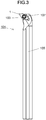
- a cutting tool 101 of the present disclosure is, for example, a rod-shaped body extending from a first end (the upper end in FIG. 3 ) to a second end (the lower end in FIG. 3 ).
- the cutting tool 101 includes a holder 105 having a pocket 103 on the first end side (tip end side) and the aforementioned insert 1 positioned in the pocket 103. Because of the provision of the insert 1, the cutting tool 101 can perform a stable cutting process over a long time period.
- the pocket 103 is a portion to which the insert 1 is attached and has a seat surface parallel to a lower surface of the holder 105 and a constraint side surface inclined relative to the seat surface.
- the pocket 103 is open on the first end side of the holder 105.
- the insert 1 is positioned in the pocket 103.
- the lower surface of the insert 1 may be in direct contact with the pocket 103, or a sheet (not illustrated) may be sandwiched between the insert 1 and the pocket 103.
- the insert 1 is attached to the holder 105 such that at least a part of a section used as the cutting edge 7 at the ridge line on which the flank face and the rake face meet protrudes outward from the holder 105.
- the insert 1 is attached to the holder 105 by a fixing screw 107. That is, the insert 1 is attached to the holder 105 by inserting the fixing screw 107 into a through hole 17 of the insert 1, inserting the tip end of the fixing screw 107 into a screw hole (not illustrated) formed in the pocket 103, and screwing the screw portions together.
- steel and cast iron can be used as the material of the holder 105.
- steel with a high toughness may be used.
- the cutting tool 101 for use in a turning process is illustrated by way of example.
- the turning process include, but are not limited to, a boring process, an external process, a grooving process, and a facing process.
- the cutting tool 101 is not limited to the one for use in the turning process.
- the insert 1 in the embodiments may be used for the cutting tool 101 for use in a milling process.
- the base was produced as follows. A molded product in the shape of a tool was produced using raw material powders in proportions indicated in Table 1, and a binder component was removed, followed by firing to produce a base. Among these samples, the bases of Sample Nos. 1 to 14 are a cermet. The base of Sample No. 15 is a superalloy. At the debindering step, the product was held in a vacuum at 200°C and 300°C each for 1 hour, and then the temperature was increased to 450°C and held for 1 hour. At the step at 450°C, CO 2 gas was introduced at a pressure of 3 kPa into a debindering furnace. Table 1 Sample No.
- a TiN layer was formed under the deposition conditions indicated in Table 2 by a CVD process under the deposition conditions indicated in Table 2.
- a TiCN layer was further formed.
- an Al 2 O 3 layer was further formed.
- the resulting insert underwent a cutting test under the following conditions.
- the width of TiN particles of Sample No. 15 using superalloy as a base exceeds 35 nm.
- the width of TiN particles in the first layer is 20 nm or less, and excellent wear resistance and fracture resistance are exhibited.
Landscapes
- Chemical & Material Sciences (AREA)
- Engineering & Computer Science (AREA)
- Mechanical Engineering (AREA)
- Organic Chemistry (AREA)
- Materials Engineering (AREA)
- Metallurgy (AREA)
- Chemical Kinetics & Catalysis (AREA)
- Inorganic Chemistry (AREA)
- General Chemical & Material Sciences (AREA)
- Ceramic Engineering (AREA)
- Cutting Tools, Boring Holders, And Turrets (AREA)
- Chemical Vapour Deposition (AREA)
- Powder Metallurgy (AREA)
Applications Claiming Priority (3)
| Application Number | Priority Date | Filing Date | Title |
|---|---|---|---|
| JP2018052842 | 2018-03-20 | ||
| JP2018223532 | 2018-11-29 | ||
| PCT/JP2019/010875 WO2019181790A1 (ja) | 2018-03-20 | 2019-03-15 | インサート及びこれを備えた切削工具 |
Publications (2)
| Publication Number | Publication Date |
|---|---|
| EP3769874A1 true EP3769874A1 (de) | 2021-01-27 |
| EP3769874A4 EP3769874A4 (de) | 2021-12-01 |
Family
ID=67986209
Family Applications (1)
| Application Number | Title | Priority Date | Filing Date |
|---|---|---|---|
| EP19770446.3A Pending EP3769874A4 (de) | 2018-03-20 | 2019-03-15 | Einsatz und damit versehenes schneidwerkzeug |
Country Status (5)
| Country | Link |
|---|---|
| EP (1) | EP3769874A4 (de) |
| JP (1) | JP7092866B2 (de) |
| KR (1) | KR102431159B1 (de) |
| CN (1) | CN111886096A (de) |
| WO (1) | WO2019181790A1 (de) |
Families Citing this family (2)
| Publication number | Priority date | Publication date | Assignee | Title |
|---|---|---|---|---|
| JP7638381B2 (ja) * | 2021-07-30 | 2025-03-03 | 京セラ株式会社 | 被覆工具および切削工具 |
| DE112023003147T5 (de) * | 2022-07-21 | 2025-06-05 | Kyocera Corporation | Beschichtetes werkzeug und schneidwerkzeug |
Family Cites Families (19)
| Publication number | Priority date | Publication date | Assignee | Title |
|---|---|---|---|---|
| JPH0615717B2 (ja) * | 1987-07-28 | 1994-03-02 | 東芝タンガロイ株式会社 | 高靱性被覆材料及びその製造方法 |
| JPH05230587A (ja) * | 1992-02-20 | 1993-09-07 | Mitsubishi Materials Corp | サ−メット |
| SE9502687D0 (sv) * | 1995-07-24 | 1995-07-24 | Sandvik Ab | CVD coated titanium based carbonitride cutting tool insert |
| BR9611817A (pt) * | 1995-10-27 | 1999-12-28 | Teledyne Ind | Revestimentos de óxido ancorados sobre ferramentas de corte demetal duro. |
| US6017488A (en) * | 1998-05-11 | 2000-01-25 | Sandvik Ab | Method for nitriding a titanium-based carbonitride alloy |
| JP2006281361A (ja) * | 2005-03-31 | 2006-10-19 | Kyocera Corp | 表面被覆部材および表面被覆切削工具 |
| SE530755C2 (sv) * | 2006-03-03 | 2008-09-02 | Sandvik Intellectual Property | Belagt cermetskär och användning därav |
| US8080312B2 (en) * | 2006-06-22 | 2011-12-20 | Kennametal Inc. | CVD coating scheme including alumina and/or titanium-containing materials and method of making the same |
| JP5111379B2 (ja) * | 2006-08-31 | 2013-01-09 | 京セラ株式会社 | 切削工具及びその製造方法並びに切削方法 |
| KR20110033293A (ko) * | 2008-07-22 | 2011-03-30 | 니혼도꾸슈도교 가부시키가이샤 | 절삭 인서트 및 절삭공구 |
| JP5413047B2 (ja) * | 2009-08-17 | 2014-02-12 | 住友電気工業株式会社 | 複合焼結体 |
| JP5560514B2 (ja) * | 2009-12-25 | 2014-07-30 | 三菱マテリアル株式会社 | 硬質被覆層がすぐれた耐欠損性を発揮する表面被覆切削工具 |
| CN101879612B (zh) * | 2010-06-28 | 2011-12-07 | 株洲钻石切削刀具股份有限公司 | 用于钢材车削的硬质合金涂层刀片 |
| JP5989930B1 (ja) | 2014-11-27 | 2016-09-07 | 京セラ株式会社 | サーメットおよび切削工具 |
| US9650714B2 (en) * | 2014-12-08 | 2017-05-16 | Kennametal Inc. | Nanocomposite refractory coatings and applications thereof |
| JP6558633B2 (ja) * | 2015-08-10 | 2019-08-14 | 三菱マテリアル株式会社 | 耐塑性変形性、耐異常損傷性および耐摩耗性にすぐれたTi基サーメット切削工具 |
| WO2017111073A1 (ja) * | 2015-12-22 | 2017-06-29 | 京セラ株式会社 | 被覆工具 |
| CN105950937B (zh) * | 2016-05-23 | 2018-01-16 | 株洲钻石切削刀具股份有限公司 | 一种硬质合金刀片及其制备方法 |
| KR102331061B1 (ko) * | 2016-08-22 | 2021-11-25 | 스미토모덴키고교가부시키가이샤 | 경질 재료 및 절삭 공구 |
-
2019
- 2019-03-15 JP JP2020507757A patent/JP7092866B2/ja active Active
- 2019-03-15 KR KR1020207029666A patent/KR102431159B1/ko active Active
- 2019-03-15 WO PCT/JP2019/010875 patent/WO2019181790A1/ja not_active Ceased
- 2019-03-15 EP EP19770446.3A patent/EP3769874A4/de active Pending
- 2019-03-15 CN CN201980020154.8A patent/CN111886096A/zh active Pending
Also Published As
| Publication number | Publication date |
|---|---|
| KR102431159B1 (ko) | 2022-08-10 |
| CN111886096A (zh) | 2020-11-03 |
| JPWO2019181790A1 (ja) | 2021-04-15 |
| EP3769874A4 (de) | 2021-12-01 |
| KR20200128150A (ko) | 2020-11-11 |
| JP7092866B2 (ja) | 2022-06-28 |
| WO2019181790A1 (ja) | 2019-09-26 |
Similar Documents
| Publication | Publication Date | Title |
|---|---|---|
| EP2267182B1 (de) | Beschichtetes Schneidwerkzeug | |
| EP1455003B1 (de) | Beschichteter Einsatz aus zementiertem Karbid | |
| EP1616976B1 (de) | Beschichteter Schneideinsatz | |
| US11311946B2 (en) | Coated tool and cutting tool including the same | |
| EP1536041B1 (de) | Beschichteter Cermet Schneideinsatz mit harter, gegen Abschiefern beständiger Beschichtung | |
| EP1548154B1 (de) | Beschichtetes Cermet Schneidwerkzeug mit harter Überzugsschicht mit hervorragender Schlagbeständigkeit. | |
| EP3766614A1 (de) | Oberflächenbeschichtetes schneidwerkzeug und herstellungsverfahren dafür | |
| US8142848B2 (en) | Coated cutting insert for milling | |
| EP1493845B1 (de) | CVD beschichteter Schneidwerkzeugeinsatz | |
| EP1352697B1 (de) | Beschichteter Schneidwerkzeugeinsatz | |
| JP7092866B2 (ja) | インサート及びこれを備えた切削工具 | |
| EP3769878A1 (de) | Einsatz und damit versehenes schneidwerkzeug | |
| EP3766613B1 (de) | Oberflächenbeschichtetes schneidwerkzeug | |
| EP3769881A1 (de) | Einsatz und schneidwerkzeug damit | |
| EP3769876A1 (de) | Werkzeug und damit versehenes schneidwerkzeug | |
| EP3769873A1 (de) | Einsatz und damit versehenes schneidwerkzeug | |
| JPH07243024A (ja) | 硬質被覆層がすぐれた密着性を有する表面被覆炭窒化チタン系サーメット製切削工具 |
Legal Events
| Date | Code | Title | Description |
|---|---|---|---|
| STAA | Information on the status of an ep patent application or granted ep patent |
Free format text: STATUS: THE INTERNATIONAL PUBLICATION HAS BEEN MADE |
|
| PUAI | Public reference made under article 153(3) epc to a published international application that has entered the european phase |
Free format text: ORIGINAL CODE: 0009012 |
|
| STAA | Information on the status of an ep patent application or granted ep patent |
Free format text: STATUS: REQUEST FOR EXAMINATION WAS MADE |
|
| 17P | Request for examination filed |
Effective date: 20201015 |
|
| AK | Designated contracting states |
Kind code of ref document: A1 Designated state(s): AL AT BE BG CH CY CZ DE DK EE ES FI FR GB GR HR HU IE IS IT LI LT LU LV MC MK MT NL NO PL PT RO RS SE SI SK SM TR |
|
| AX | Request for extension of the european patent |
Extension state: BA ME |
|
| DAV | Request for validation of the european patent (deleted) | ||
| DAX | Request for extension of the european patent (deleted) | ||
| A4 | Supplementary search report drawn up and despatched |
Effective date: 20211103 |
|
| RIC1 | Information provided on ipc code assigned before grant |
Ipc: C23C 16/34 20060101ALI20211027BHEP Ipc: C22C 29/04 20060101ALI20211027BHEP Ipc: B22F 5/00 20060101ALI20211027BHEP Ipc: B22F 3/24 20060101ALI20211027BHEP Ipc: C22C 29/00 20060101ALI20211027BHEP Ipc: C23C 28/04 20060101ALI20211027BHEP Ipc: C23C 30/00 20060101ALI20211027BHEP Ipc: C23C 16/40 20060101ALI20211027BHEP Ipc: C23C 16/36 20060101ALI20211027BHEP Ipc: B23B 27/14 20060101AFI20211027BHEP |
|
| P01 | Opt-out of the competence of the unified patent court (upc) registered |
Effective date: 20230505 |
|
| STAA | Information on the status of an ep patent application or granted ep patent |
Free format text: STATUS: EXAMINATION IS IN PROGRESS |
|
| 17Q | First examination report despatched |
Effective date: 20250324 |
|
| GRAP | Despatch of communication of intention to grant a patent |
Free format text: ORIGINAL CODE: EPIDOSNIGR1 |
|
| STAA | Information on the status of an ep patent application or granted ep patent |
Free format text: STATUS: GRANT OF PATENT IS INTENDED |