EP3769906A1 - Procédé de fabrication de véhicules automobiles - Google Patents
Procédé de fabrication de véhicules automobiles Download PDFInfo
- Publication number
- EP3769906A1 EP3769906A1 EP19188413.9A EP19188413A EP3769906A1 EP 3769906 A1 EP3769906 A1 EP 3769906A1 EP 19188413 A EP19188413 A EP 19188413A EP 3769906 A1 EP3769906 A1 EP 3769906A1
- Authority
- EP
- European Patent Office
- Prior art keywords
- docking plate
- motor vehicle
- docking
- base frame
- base
- Prior art date
- Legal status (The legal status is an assumption and is not a legal conclusion. Google has not performed a legal analysis and makes no representation as to the accuracy of the status listed.)
- Granted
Links
Images



Classifications
-
- B—PERFORMING OPERATIONS; TRANSPORTING
- B62—LAND VEHICLES FOR TRAVELLING OTHERWISE THAN ON RAILS
- B62D—MOTOR VEHICLES; TRAILERS
- B62D65/00—Designing, manufacturing, e.g. assembling, facilitating disassembly, or structurally modifying motor vehicles or trailers, not otherwise provided for
- B62D65/02—Joining sub-units or components to, or positioning sub-units or components with respect to, body shell or other sub-units or components
- B62D65/024—Positioning of sub-units or components with respect to body shell or other sub-units or components
- B62D65/026—Positioning of sub-units or components with respect to body shell or other sub-units or components by using a jig or the like; Positioning of the jig
-
- B—PERFORMING OPERATIONS; TRANSPORTING
- B62—LAND VEHICLES FOR TRAVELLING OTHERWISE THAN ON RAILS
- B62D—MOTOR VEHICLES; TRAILERS
- B62D65/00—Designing, manufacturing, e.g. assembling, facilitating disassembly, or structurally modifying motor vehicles or trailers, not otherwise provided for
- B62D65/02—Joining sub-units or components to, or positioning sub-units or components with respect to, body shell or other sub-units or components
- B62D65/024—Positioning of sub-units or components with respect to body shell or other sub-units or components
-
- B—PERFORMING OPERATIONS; TRANSPORTING
- B23—MACHINE TOOLS; METAL-WORKING NOT OTHERWISE PROVIDED FOR
- B23P—METAL-WORKING NOT OTHERWISE PROVIDED FOR; COMBINED OPERATIONS; UNIVERSAL MACHINE TOOLS
- B23P21/00—Machines for assembling a multiplicity of different parts to compose units, with or without preceding or subsequent working of such parts, e.g. with program control
-
- B—PERFORMING OPERATIONS; TRANSPORTING
- B23—MACHINE TOOLS; METAL-WORKING NOT OTHERWISE PROVIDED FOR
- B23P—METAL-WORKING NOT OTHERWISE PROVIDED FOR; COMBINED OPERATIONS; UNIVERSAL MACHINE TOOLS
- B23P19/00—Machines for simply fitting together or separating metal parts or objects, or metal and non-metal parts, whether or not involving some deformation; Tools or devices therefor so far as not provided for in other classes
- B23P19/04—Machines for simply fitting together or separating metal parts or objects, or metal and non-metal parts, whether or not involving some deformation; Tools or devices therefor so far as not provided for in other classes for assembling or disassembling parts
-
- B—PERFORMING OPERATIONS; TRANSPORTING
- B23—MACHINE TOOLS; METAL-WORKING NOT OTHERWISE PROVIDED FOR
- B23Q—DETAILS, COMPONENTS, OR ACCESSORIES FOR MACHINE TOOLS, e.g. ARRANGEMENTS FOR COPYING OR CONTROLLING; MACHINE TOOLS IN GENERAL CHARACTERISED BY THE CONSTRUCTION OF PARTICULAR DETAILS OR COMPONENTS; COMBINATIONS OR ASSOCIATIONS OF METAL-WORKING MACHINES, NOT DIRECTED TO A PARTICULAR RESULT
- B23Q1/00—Members which are comprised in the general build-up of a form of machine, particularly relatively large fixed members
- B23Q1/0063—Connecting non-slidable parts of machine tools to each other
- B23Q1/0081—Connecting non-slidable parts of machine tools to each other using an expanding clamping member insertable in a receiving hole
-
- B—PERFORMING OPERATIONS; TRANSPORTING
- B25—HAND TOOLS; PORTABLE POWER-DRIVEN TOOLS; MANIPULATORS
- B25H—WORKSHOP EQUIPMENT, e.g. FOR MARKING-OUT WORK; STORAGE MEANS FOR WORKSHOPS
- B25H1/00—Work benches; Portable stands or supports for positioning portable tools or work to be operated on thereby
- B25H1/0007—Work benches; Portable stands or supports for positioning portable tools or work to be operated on thereby for engines, motor-vehicles or bicycles
-
- B—PERFORMING OPERATIONS; TRANSPORTING
- B62—LAND VEHICLES FOR TRAVELLING OTHERWISE THAN ON RAILS
- B62D—MOTOR VEHICLES; TRAILERS
- B62D65/00—Designing, manufacturing, e.g. assembling, facilitating disassembly, or structurally modifying motor vehicles or trailers, not otherwise provided for
- B62D65/02—Joining sub-units or components to, or positioning sub-units or components with respect to, body shell or other sub-units or components
-
- B—PERFORMING OPERATIONS; TRANSPORTING
- B62—LAND VEHICLES FOR TRAVELLING OTHERWISE THAN ON RAILS
- B62D—MOTOR VEHICLES; TRAILERS
- B62D65/00—Designing, manufacturing, e.g. assembling, facilitating disassembly, or structurally modifying motor vehicles or trailers, not otherwise provided for
- B62D65/02—Joining sub-units or components to, or positioning sub-units or components with respect to, body shell or other sub-units or components
- B62D65/18—Transportation, conveyor or haulage systems specially adapted for motor vehicle or trailer assembly lines
-
- B—PERFORMING OPERATIONS; TRANSPORTING
- B23—MACHINE TOOLS; METAL-WORKING NOT OTHERWISE PROVIDED FOR
- B23P—METAL-WORKING NOT OTHERWISE PROVIDED FOR; COMBINED OPERATIONS; UNIVERSAL MACHINE TOOLS
- B23P2700/00—Indexing scheme relating to the articles being treated, e.g. manufactured, repaired, assembled, connected or other operations covered in the subgroups
- B23P2700/50—Other automobile vehicle parts, i.e. manufactured in assembly lines
Definitions
- the present invention relates to a method for the production of motor vehicles by means of a device for positioning motor vehicle parts and a device for the production of motor vehicles comprising a device for positioning motor vehicle parts.
- the DE 198 20 094 A1 discloses, for example, a system for positioning and welding body parts of different types of motor vehicles with an assembly frame guided on a conveyor track which has receptacles for at least some body parts, with positioning devices for the body parts and with at least one for Robots that can be used for welding work, the assembly frame having positioning devices for at least some body parts and externally actuated clamping devices for the body parts, with a further conveyor track being arranged below the conveyor track, on which one of several auxiliary assembly frames is guided, with parking positions for the lower conveyor track Assembly subframes are provided, the assembly subframes each having receptacles for further body parts of different vehicle types as well as devices for positioning and bracing with the assembly frame, and wherein a lifting device is provided for the assembly subframe.
- a device for the production of motor vehicles which comprises exchangeable docking plates, with motor vehicle parts, in particular bodies or body parts, being held on the docking plates.
- Different docking plates can be placed on the same base frame to build different types of motor vehicles.
- receptacles which are usually precisely matched to the motor vehicle parts to be taken up and are therefore designed as a function of the motor vehicle type.
- these recordings are not attached directly, for example, to a frame of a work station or device, but rather to an exchangeable docking plate, i.e. an essentially plate-shaped element that is easily, preferably also automated, in particular by means of gripping systems or robots, in a basic module is fixable, attached.
- the docking plate of the device can therefore be changed in a simple manner and in particular in an automated manner, so that new, suitable receptacles are also provided for the new motor vehicle parts.
- a docking plate is fed to a base frame equipped with at least one base module and the docking plate is fixed on the base module on the base frame.
- the assembly of the base frame or the base module on the base frame with the docking plate takes place in a configuration station.
- a motor vehicle part in particular a body or a body part, is placed on the docking plate so that the motor vehicle part is held by the receptacles in the docking plate.
- the motor vehicle part is then equipped with add-on parts in order to supplement or complete the motor vehicle to be manufactured.
- the equipping with add-on parts can preferably take place in the same work station as the mounting of the motor vehicle part.
- the same base frames and the same base modules can be used for the production of different types of motor vehicles.
- the base frames therefore do not have to be disposed of when retrofitting to a different vehicle type, for example. Rather, suitable docking plates only have to be placed on the base frame and the base modules in a configuration station.
- the base frames are therefore reusable. Suitable docking modules for different vehicle types can be stored in a space-saving manner and made available when required.
- the device for performing the method namely the device for positioning motor vehicle parts, is explained in more detail below.
- the docking plate can preferably be fixed or fixed in the base module with a precise position and / or precise tolerance.
- the docking plate preferably comprises bolts, in particular draw-in tensioning bolts, the docking plate being fixed in a precisely positioned position in the base module by means of the bolts.
- the docking plate particularly preferably comprises two or four bolts or pull-in tensioning bolts, which can be attached in particular in the area of the corners of a square docking plate.
- the bolts are preferably formed in the position of use on the underside of the docking plate and preferably protrude vertically downwards.
- the base module preferably comprises at least one clamping device, particularly preferably a zero point clamping device and / or a locking device, which is designed to clamp bolts, in particular draw-in clamping bolts, and / or to fix and / or lock the docking plate on the base module in some other way.
- the basic module preferably forms a so-called zero-point clamping system and / or zero-point locking system for receiving a docking plate with precise positions and / or tolerances.
- a base module fixedly mounted on a base frame with one or more zero point clamping devices and at least one docking plate that can be exchanged or detached on the base module can together form a "docking module”.
- the basic module preferably comprises a media interface, a medium being able to be fed to the basic module via the media interface, in particular compressed air and / or electrical signals and / or electricity.
- the compressed air can be used to lock the draw-in clamping bolts located on the docking plate on the basic module, in particular on the zero point system.
- the transmission of current and / or electrical signals into the basic module can also take place inductively.
- the recordings can include supports, consoles and / or tensioners.
- the receptacles can in particular be designed specifically for the type of vehicle.
- the receptacles can be designed as separate components and fastened to the docking plate, in particular fastened detachably and exchangeably.
- the docking plate preferably comprises holding elements, for example bolts, clamping bolts or similar elements, which are designed so that the docking plate can be positioned on the basic module and / or removed from the basic module by means of a gripping system engaging the holding elements.
- holding elements for example bolts, clamping bolts or similar elements, which are designed so that the docking plate can be positioned on the basic module and / or removed from the basic module by means of a gripping system engaging the holding elements.
- the device preferably comprises at least one gripping system, in particular a robot, the gripping system being designed to position the docking plate on the basic module and / or to remove it from the basic module.
- the docking plate is preferably fetched from a store by the gripping system, in particular the robot, in order to be attached to the basic module and, after being removed from the basic module from the gripping system, placed in a store.
- the device preferably comprises at least one further, preferably automatically exchangeable, docking plate, the further docking plate being fixable in the same base module in which the docking plate can be fixed, with further receptacles being formed on the further docking plate and with the further receptacles of the further docking plate being different from the recordings of the docking plate are formed.
- At least two differently designed docking plates can therefore be fixed in a basic module.
- the different docking plates can be used to manufacture different types of vehicles will.
- the base frame and the base modules do not have to be exchanged for this.
- some docking plates have no receptacles, since, for example, only two docking plates equipped with receptacles are required for the production of a specific vehicle type on a base frame that has three basic modules. An empty docking plate or a docking plate without receptacles can then be docked or fixed on a base module, for example to protect or cover the clamping devices.
- the device preferably comprises at least two, preferably at least three basic modules and at least two, preferably at least three, automatically exchangeable docking plates, the docking plates being fixable or fixed in a precise position in a respective basic module, with receptacles being formed on each docking plate.
- Several basic modules for the simultaneous fixation of several docking plates can thus be formed in a base frame.
- a docking plate can also be exchangeable manually, for example by lifting the docking plate with a manually controlled manipulator or stacker.
- a basic module for the production of motor vehicles of the first motor vehicle type can be automatically equipped with a docking plate, with receptacles formed on the docking plate that are designed for this purpose .
- Automotive parts of a motor vehicle of the first motor vehicle type, and the basic module for the production of motor vehicles of the second motor vehicle type is automatically equipped with a further docking plate, further receptacles being formed on the further docking plate, which are designed to hold motor vehicle parts of a motor vehicle of the second motor vehicle type .
- the base frame and base modules can therefore continue to be used and only the clamped docking plates with their vehicle-type-specific receptacles are exchanged.
- the docking plate for feeding to the base frame equipped with the at least one base module is preferably removed in the configuration station by means of a gripping system, in particular a robot, from a warehouse, in particular from a shelf.
- the space required for storage is significantly reduced, since only the individual docking plates, including type-specific mountings, have to be stored on the shelf and the supporting base frame for the next vehicle type does not have to be put down or replaced, but after being loaded with the one that is suitable for the next vehicle type Docking plates can be used again immediately.
- the equipped motor vehicle part can be removed from the docking plate and then the base frame, preferably with the at least one base module arranged on the base frame, particularly preferably with the Docking plate fixed on the base module, placed in a configuration station - for example in the same configuration station in which the base frame was previously equipped with the docking plate.
- the base frame, with or without a base module and docking plate can be moved to a storage station.
- the base frame no longer has to be scrapped or disposed of, but can be used again immediately for the next project or the next vehicle type.
- two different docking plates can be fixed on two base modules arranged on the same base frame.
- the different types of motor vehicle are then produced "in series with one another" on stations.
- two different docking plates can also be fixed on two base modules arranged on two different base frames.
- the different types of motor vehicle are then produced "parallel to one another" on stations.
- the storage spaces for individual docking plates in the warehouse, in particular a shelf, are preferably stored in a storage unit.
- "Individual" docking plate means that not only the information is saved that a (any) docking plate is located at this parking space, but a specific docking plate with certain properties and / or with a unique identification number.
- the tolerance parameters for individual docking plates can be calculated from tolerance measurements of a base frame with a base module and with the individual docking plate and from tolerance measurements of the base frame with the base module without the individual docking plate. As a result, tolerance parameters for the docking plates do not have to be measured directly on the docking plates, so that a more efficient production process or shorter cycle times can be achieved.
- a control unit preferably controls the gripping system in such a way that, depending on the stored measured values and / or the stored parking spaces, an individual docking plate is removed from the shelf for feeding to the base frame equipped with the at least one basic module in the configuration station.
- a docking plate can be removed and placed on a base frame, the geometric deviations of which from a target value compensate for the deviations of the base frame used and / or the base module used, so that overall lower deviations or better tolerance values for the overall device base frame including base module including docking plate are achieved can be.
- a device according to the invention for the production of motor vehicles can thus comprise a device for positioning motor vehicle parts, as described above, and additionally comprise: a warehouse in which several docking plates are kept ready and a gripping system, in particular a robot, the gripping system being designed to to remove a docking plate from a store and to feed it to the base frame equipped with at least one base module and to fix the docking plate on the base module.
- the device preferably also comprises a control unit, the control unit controlling the gripping system in such a way that, depending on stored measured values and / or stored storage spaces, in particular in the manner described in more detail above, an individual docking plate is removed from the shelf. The individual docking plate can then be fed from the gripping system to the base frame equipped with the at least one base module.
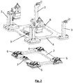
- a device according to the invention for the production of motor vehicles comprising a device for positioning motor vehicle parts, and thus also a device for positioning motor vehicle parts for a method according to the invention for producing motor vehicles is shown.
- the motor vehicle parts can be positioned on docking plates 4 for further processing, in particular for equipping the motor vehicle to be manufactured with additional components.
- FIG Fig. 2 Several docking plates 4 can be mounted on a common base frame 1, on base modules 2 (shown in FIG Fig. 2 ).
- the basic modules 2 and the docking plates 4 have a flat shape. Viewed from above, basic modules 2 and docking plates 4 have a rectangular or square shape.
- base modules 2 and docking plates 4 can essentially form a rectangular or square frame, the frame of a docking plate 4 essentially fitting onto the frame of a base module 2.
- the docking plates 4 are kept ready in a warehouse 10, in particular in one or more shelves, for example on the side of the base frame 1, and can be removed from their place in the warehouse 10 by gripping systems 9, in particular on robots, and positioned on the base modules 2 for provision suitable recordings 3 (shown in Fig. 2 ) for the production of a certain type of vehicle.
- the device thus comprises a base frame 1, several base modules 2 arranged on the base frame 1, as well as automatically exchangeable docking plates 4, wherein the docking plates 4 can be fixed in the base modules 2 in a precisely positioned manner. All basic modules 2 and all docking plates 4 preferably have the same dimensions, so that all docking plates 4 can be fixed on all basic modules 2 as desired.
- receptacles 3 are formed on the docking plates in order to be able to hold motor vehicle parts in a predetermined position by means of the receptacles 3.
- the receptacles 3 can comprise supports, consoles and / or tensioners and / or retractable / retractable positioning pins.
- a docking plate 4 has bolts 5 on its underside, in particular four draw-in clamping bolts, so that the docking plate 4 can be fixed in a precise position in a base module 2 by means of the bolts 5.
- a basic module 2 therefore has, as in Fig. 2 shown, four appropriately positioned clamping devices 6, in particular zero point clamping devices, which are designed to clamp the bolts 5, in particular draw-in clamping bolts, of a docking plate 4.
- the basic module 2 thereby preferably forms a zero point clamping system.
- a basic module 2 can comprise a media interface 7, wherein a medium can be fed to the basic module 2 via the media interface 7, in particular compressed air and / or electrical signals and / or electricity.
- the compressed air can be used, for example, to lock the draw-in clamping bolts 5 located on the docking plate 4 by means of clamping devices 6, preferably zero point clamping devices, on the zero point system or on the basic module 2.
- a docking plate 4 also comprises holding elements 8, for example again bolts, clamping bolts, or the like, the holding elements preferably being arranged on the top of the docking plates 4.
- the holding elements 8 are designed so that the docking plates 4 by means of a gripping system 9 engaging the holding elements 8 ( Fig. 1 ) can be positioned on the basic module 2 and / or removed from the basic module 2.
- a basic module 2 is automated, preferably by means of a gripping system 9, equipped with a docking plate 4, with receptacles 3 being formed on the docking plate 4 which are designed for this purpose are to hold motor vehicle parts of a motor vehicle of the first motor vehicle type.
- the basic module 2 is automated, preferably by means of a gripping system 9, equipped with a further, i.e. different, docking plate 4, further receptacles 3 being formed on the further docking plate 4 which are designed to hold motor vehicle parts of a motor vehicle of the second motor vehicle type.
- the other receptacles 3 are therefore at least partially different from the receptacles 3, so that only other motor vehicle parts or motor vehicle parts can be positioned in a different way in order to produce a different type of motor vehicle.
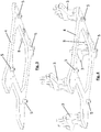
- Fig. 5 shows a plan view of a base frame 1 with three base modules 2 of the device according to FIG Fig. 1 .
- the base frame 1 thus serves to accommodate three docking plates 4.
- Each base module 2 comprises a media interface 7.
- Fig. 6 is a schematic representation of a method according to the invention for the production of motor vehicles.
- a configuration station 11 which, for example, has at least the equipment as in Fig. 1 has shown, docking plates 4 are delivered to base frame 1, the base frames 1 being equipped with at least one base module 2 and the docking plates 4 being fixed on the respective base modules 2.
- type changes can therefore be made for the production of a different vehicle type.
- the type of motor vehicle thus defines 13.
- the base frames 1 and / or the base modules 2 and / or the docking plates 4 can also be parked or stored in the configuration stations 11 and measurements, in particular tolerance measurements, can be carried out in the configuration station 11.
- a motor vehicle part in particular a body part, can be placed on the docking plate 4, so that the motor vehicle part is held by the receptacles 3 of the docking plate 4.
- the production of the specific motor vehicle type can then be carried out, and production thus starts 14.
- the motor vehicle part can be equipped with add-on parts.
- the equipped motor vehicle part After equipping the motor vehicle part with add-on parts, the equipped motor vehicle part is removed from the docking plate 4. A new motor vehicle part can be placed on the docking plate 4 for fitting with add-on parts.
- the base frame without the motor vehicle part 17, in particular a base frame 1 with base modules 2 and with docking plates 4 fixed on the base modules 2, can be returned to the configuration station 11 or to a storage station 18 or a buffer. From the storage station 18 can Base frame 1 can later be brought back into configuration station 11.
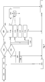
- Fig. 7 is a schematic representation of partial aspects of a method according to the invention for the production of motor vehicles, namely with regard to the measurement of base frame 1, base module 2 and docking plates 4, including receptacles 3, for the selection and removal of the optimal docking plate 4 from the shelf, namely an intelligent one Register shelf in order to be able to position the motor vehicle part with the smallest possible positional deviation and still within the permitted tolerance for the production process.
- the sequence begins with a base frame 1 being controlled from a storage station 18, 101, that is to say being controlled from a waiting position.
- the central part of the measurement method starts with the decision 109 as to whether palletizing is necessary, that is to say whether the base frame 1 is to be equipped with a new docking plate 4.
- an input measurement of the "ACTUAL" recordings takes place at 110, that is, a measurement of the actual state of base frame 1, docking plates 2 and docking plate (s) 4 still on base frame 1, including their recordings 3.
- step 114 If the state of the docking plates 4 and their receptacles 3 is OK (OK), storage space is deposited, step 114.
- the docking plate (s) 4 are removed from the base frame 1 or from the base module 2 and placed in an empty storage space, in particular empty shelf space. From there, the docking plates can later be re-palletized, 112, that is, can be used for attachment to another base frame 1.
- an input measurement of the basic module to the base frame "IST” takes place at 111, that is, a measurement of the base frame 1 and the one or more base modules 2 fixedly connected to the base frame 1 and their deviation from reference points on Base frame 1, i.e. a measurement without docking plates 4.
- the box 115 represents a PLC (programmable logic controller) for controlling the measurement process and the dashed arrows from 110 and 111 to the PLC 115 represent the transmission of the measurement data obtained to the PLC.
- PLC programmable logic controller
- the PLC calculates the actual deviation of the undocked docking plate 4 on the receptacles 3 in relation to the basic module 2 on the base frame 1. Since the docking plate cannot be measured in any "master base frame" in the configuration station to improve the cycle times, the tolerance preferably calculated back via the docking module / base module 2 on the base frame 1.
- the measurement data of the docking plate 4 are stored via the PLC control on the respectively allocated storage space of the docking plate (s) 4 on the shelf (register shelf).
- the arrow from box 115 vertically downward symbolizes that, alternatively, parallel to the direct step from 111, input measurement of basic module to base frame "IS", to 112, reloading of pallets, if the measurement results were okay, a "best fit” tolerance calculation and docking plate selection can be made from the respective shelf space.
- the docking plate (s) that best fit in terms of tolerance for the already measured and now pending base frame 1, from all the docking plates 4 present on the shelf, are calculated.
- the palletizing or type change of the docking plate 4 finally takes place: Robots grab the computationally determined, best fitting docking plate (s) 4 from the respective storage location in the register shelf. Then the docking / palletizing of the new docking plate 4 onto the base frame 1 or onto the base module (s) 2.
- the measured value from the measurement according to point 113 is compared with a permissible tolerance value defined in the system. If the new measured value or the new tolerance value is not in order (not OK), the base frame 1 is discharged for a measuring technique 116, that is to say for servicing, maintenance, measuring technique or some other more precise check.
- the base frame 1 which is now equipped with the new docking plates 4, is allowed to move into the production plant, namely a work station 12.
- 104 shows the smuggling into the workstation.
- a measurement is also shown, which can be carried out optionally.
- the parts of the device, in particular docking plates 4, can also be measured if no palletizing or docking of a new docking plate 4 has to take place, but also independently of this, namely whenever a base frame 1 has a predefined number of production cycles behind it. It is an additional checking criterion or an additional trigger for a measurement or quality control of the device parts.
- 105 represents the check of whether a measurement is necessary according to the number of revolutions. If this is not the case, either a measurement is carried out due to palletizing, 109, as described above, or the base frame 1 can be fed back into a work station 12 after a parking position 102 and possibly after a certain dwell time 103, 104.
- a measurement is to be carried out according to 105, an input measurement of the recordings "ACTUAL", 106, takes place, similar to step 110. If the measured values are OK (OK), the measurement data are stored separately for docking plates 4 and / or the overall structure 1, 2, 4 in step 107. The entire sheeting can then be fed in again, 108, for production in the work station, 104.
- step 106 If the measured tolerances in step 106 are not in order, the equipped base frame 1 for the measurement technology 116 is discharged, i.e. again for servicing, maintenance, measurement technology or another more precise check, as it also occurs when one of the tests 110, 111 and 113 gives an unacceptable result.
Landscapes
- Engineering & Computer Science (AREA)
- Mechanical Engineering (AREA)
- Manufacturing & Machinery (AREA)
- Chemical & Material Sciences (AREA)
- Combustion & Propulsion (AREA)
- Transportation (AREA)
- Automatic Assembly (AREA)
Priority Applications (3)
| Application Number | Priority Date | Filing Date | Title |
|---|---|---|---|
| EP19188413.9A EP3769906B1 (fr) | 2019-07-25 | 2019-07-25 | Procédé et dispositif de fabrication de véhicules automobiles |
| US16/932,168 US11518458B2 (en) | 2019-07-25 | 2020-07-17 | Method for the production of motor vehicles |
| CN202010697392.7A CN112278113B (zh) | 2019-07-25 | 2020-07-20 | 用于生产汽车的方法 |
Applications Claiming Priority (1)
| Application Number | Priority Date | Filing Date | Title |
|---|---|---|---|
| EP19188413.9A EP3769906B1 (fr) | 2019-07-25 | 2019-07-25 | Procédé et dispositif de fabrication de véhicules automobiles |
Publications (2)
| Publication Number | Publication Date |
|---|---|
| EP3769906A1 true EP3769906A1 (fr) | 2021-01-27 |
| EP3769906B1 EP3769906B1 (fr) | 2022-02-02 |
Family
ID=67438931
Family Applications (1)
| Application Number | Title | Priority Date | Filing Date |
|---|---|---|---|
| EP19188413.9A Active EP3769906B1 (fr) | 2019-07-25 | 2019-07-25 | Procédé et dispositif de fabrication de véhicules automobiles |
Country Status (3)
| Country | Link |
|---|---|
| US (1) | US11518458B2 (fr) |
| EP (1) | EP3769906B1 (fr) |
| CN (1) | CN112278113B (fr) |
Cited By (1)
| Publication number | Priority date | Publication date | Assignee | Title |
|---|---|---|---|---|
| CN119057362A (zh) * | 2024-09-26 | 2024-12-03 | 重庆长安工业(集团)有限责任公司 | 大型复杂组件自动化焊接用定位装置 |
Families Citing this family (1)
| Publication number | Priority date | Publication date | Assignee | Title |
|---|---|---|---|---|
| US11668430B2 (en) * | 2020-09-30 | 2023-06-06 | Robert Green | Engine mount stand |
Citations (6)
| Publication number | Priority date | Publication date | Assignee | Title |
|---|---|---|---|---|
| JPH05277848A (ja) * | 1992-03-30 | 1993-10-26 | Nissan Shatai Co Ltd | 車体支持装置 |
| DE19820094A1 (de) * | 1998-05-06 | 1999-11-18 | Thyssen Industrie | Anlage zum Positionieren und Verschweißen von Karosserieteilen unterschiedlicher Kfz-Typen |
| KR20030005855A (ko) * | 2001-07-10 | 2003-01-23 | 현대자동차주식회사 | 차량용 부품 로딩 시스템 |
| CN105882789A (zh) * | 2016-05-10 | 2016-08-24 | 南京中设焊接装备开发有限公司 | 一种生产线用滑动切换装置及切换方法 |
| DE202017102155U1 (de) * | 2017-04-11 | 2018-07-24 | Kuka Systems Gmbh | Fertigungsstation |
| US20180273243A1 (en) * | 2017-03-22 | 2018-09-27 | Comau Llc | Modular Reconfigurable Vehicle Assembly Pallet |
Family Cites Families (8)
| Publication number | Priority date | Publication date | Assignee | Title |
|---|---|---|---|---|
| DE102006049647A1 (de) | 2006-10-20 | 2008-04-30 | Audi Ag | Arbeitsstation zur Verbindung von Karosserieteilen eines Kraftfahrzeugs, Fertigungsstraße mit einer solchen Arbeitsstation sowie Verfahren zum Zustellen/Wechseln von Spannrahmen in einer Arbeitsstation |
| US20080172857A1 (en) | 2007-01-05 | 2008-07-24 | Tennessee Rand Automation | Systems and Methods for Manipulating a Frame in a Manufacturing Process |
| DE102007042187B3 (de) * | 2007-08-28 | 2009-04-09 | IPR-Intelligente Peripherien für Roboter GmbH | Werkzeugwechselsystem für einen Industrieroboter |
| KR101305189B1 (ko) * | 2011-11-07 | 2013-09-12 | 기아자동차주식회사 | 차량용 패널 클램핑 장치 |
| US10710245B2 (en) * | 2016-07-08 | 2020-07-14 | The Boeing Company | Quick-change clamp arms for robot end effectors, systems including the same, and related methods |
| JP2018207022A (ja) * | 2017-06-08 | 2018-12-27 | 株式会社ディスコ | 加工装置 |
| EP4000798A1 (fr) * | 2019-07-25 | 2022-05-25 | Magna Steyr Fahrzeugtechnik AG & Co KG | Dispositif de positionnement de pièces de véhicule automobile |
| CA3184660A1 (fr) * | 2020-05-15 | 2021-11-18 | Meso Scale Technologies, Llc. | Couvercles amovibles compatibles avec l'automatisation et procedes d'utilisation |
-
2019
- 2019-07-25 EP EP19188413.9A patent/EP3769906B1/fr active Active
-
2020
- 2020-07-17 US US16/932,168 patent/US11518458B2/en active Active
- 2020-07-20 CN CN202010697392.7A patent/CN112278113B/zh active Active
Patent Citations (6)
| Publication number | Priority date | Publication date | Assignee | Title |
|---|---|---|---|---|
| JPH05277848A (ja) * | 1992-03-30 | 1993-10-26 | Nissan Shatai Co Ltd | 車体支持装置 |
| DE19820094A1 (de) * | 1998-05-06 | 1999-11-18 | Thyssen Industrie | Anlage zum Positionieren und Verschweißen von Karosserieteilen unterschiedlicher Kfz-Typen |
| KR20030005855A (ko) * | 2001-07-10 | 2003-01-23 | 현대자동차주식회사 | 차량용 부품 로딩 시스템 |
| CN105882789A (zh) * | 2016-05-10 | 2016-08-24 | 南京中设焊接装备开发有限公司 | 一种生产线用滑动切换装置及切换方法 |
| US20180273243A1 (en) * | 2017-03-22 | 2018-09-27 | Comau Llc | Modular Reconfigurable Vehicle Assembly Pallet |
| DE202017102155U1 (de) * | 2017-04-11 | 2018-07-24 | Kuka Systems Gmbh | Fertigungsstation |
Cited By (1)
| Publication number | Priority date | Publication date | Assignee | Title |
|---|---|---|---|---|
| CN119057362A (zh) * | 2024-09-26 | 2024-12-03 | 重庆长安工业(集团)有限责任公司 | 大型复杂组件自动化焊接用定位装置 |
Also Published As
| Publication number | Publication date |
|---|---|
| CN112278113A (zh) | 2021-01-29 |
| CN112278113B (zh) | 2022-11-01 |
| US20210024153A1 (en) | 2021-01-28 |
| EP3769906B1 (fr) | 2022-02-02 |
| US11518458B2 (en) | 2022-12-06 |
Similar Documents
| Publication | Publication Date | Title |
|---|---|---|
| DE69815124T2 (de) | Verfahren, anordnung und einrichtung für automontage | |
| EP3157804B1 (fr) | Plaque de réception segmentée pour une pièce à usiner | |
| DE102016225012B4 (de) | Hauptmontage-Einheit für ein Fahrzeugkarosserie-Montagesystem sowie Steuerungsverfahren dafür | |
| DE69102929T2 (de) | Verfahren und Vorrichtung für eine variable, automatische Zusammenstellung eines Aufbaus. | |
| EP0968073A1 (fr) | Procede et dispositif pour amener, serrer et usiner des pieces, en particulier pour le soudage geometrique de pieces de carrosseries automobiles dans une station d'usinage | |
| EP3769905B1 (fr) | Dispositif de positionnement de pièces de véhicule automobile et procédé pour configurer sélectivement un tel dispositif | |
| EP1890929B1 (fr) | Procede pour assembler des pieces d'une carrosserie de vehicule | |
| EP0977651A1 (fr) | Procede et dispositif de fabrication de pieces complexes | |
| WO1995032886A1 (fr) | Procede et dispositif permettant d'amener, de maintenir en position et d'usiner les pieces d'une carrosserie de vehicule | |
| EP2416927B1 (fr) | Procédé d'assemblage automatique de deux pièces | |
| DE102008032909B4 (de) | Verfahren und Fertigungseinrichtung zum Fertigen von Rohkarosserien von Fahrzeugen | |
| EP3769906B1 (fr) | Procédé et dispositif de fabrication de véhicules automobiles | |
| DE102018007932A1 (de) | Produktionsanlage sowie Verfahren zur Herstellung von Kraftfahrzeugen | |
| DE60121941T2 (de) | Herstellungsverfahren und herstellungsanlage | |
| EP2524861B1 (fr) | Dispositif et procédé de manipulation d'un support d'outil de montage de véhicule sur une ligne de fabrication de véhicule, support d'outil de montage de véhicule et station de montage | |
| DE102013016827B4 (de) | Produktionssystem und Verfahren zum Herstellen unterschiedlicher Rohbaugruppenvarianten | |
| DE202007009015U1 (de) | Fügestation für Karosseriebauteile | |
| EP2067568B1 (fr) | Chaîne de production pour le montage de différents modèles | |
| DE102017206136B4 (de) | System zum Transportieren von unterschiedlich ausgestalteten Bauteilen | |
| EP2521944B1 (fr) | Cellule de fabrication flexible | |
| DE29923946U1 (de) | Anlage für den flexiblen Zusammenbau von Kfz-Karosserien | |
| DE102011014911A1 (de) | Verfahren zur automatisierten Montage eines Befestigungselementes an einem Fahrzeugkarosseriebereich sowie Montagewerkzeug | |
| DE102014009862A1 (de) | Anbindungssystem für eine Traktionsbatterie eines Kraftfahrzeugs | |
| DE102006062442B3 (de) | Fertigungseinrichtung für Bauteile, insbesondere Karosseriebauteile von Kraftfahrzeugen | |
| DE4326318A1 (de) | Verfahren, Magazinier- und Reinigungs-Einrichtung und Großplotter zum automatischen Säubern und Einrüsten von Paletten mit Querabstellern |
Legal Events
| Date | Code | Title | Description |
|---|---|---|---|
| PUAI | Public reference made under article 153(3) epc to a published international application that has entered the european phase |
Free format text: ORIGINAL CODE: 0009012 |
|
| STAA | Information on the status of an ep patent application or granted ep patent |
Free format text: STATUS: REQUEST FOR EXAMINATION WAS MADE |
|
| 17P | Request for examination filed |
Effective date: 20201216 |
|
| AK | Designated contracting states |
Kind code of ref document: A1 Designated state(s): AL AT BE BG CH CY CZ DE DK EE ES FI FR GB GR HR HU IE IS IT LI LT LU LV MC MK MT NL NO PL PT RO RS SE SI SK SM TR |
|
| AX | Request for extension of the european patent |
Extension state: BA ME |
|
| RIC1 | Information provided on ipc code assigned before grant |
Ipc: B23P 21/00 20060101AFI20210531BHEP Ipc: B62D 65/02 20060101ALI20210531BHEP Ipc: B23K 37/04 20060101ALI20210531BHEP Ipc: B25H 1/00 20060101ALI20210531BHEP |
|
| GRAP | Despatch of communication of intention to grant a patent |
Free format text: ORIGINAL CODE: EPIDOSNIGR1 |
|
| STAA | Information on the status of an ep patent application or granted ep patent |
Free format text: STATUS: GRANT OF PATENT IS INTENDED |
|
| INTG | Intention to grant announced |
Effective date: 20210728 |
|
| GRAS | Grant fee paid |
Free format text: ORIGINAL CODE: EPIDOSNIGR3 |
|
| GRAA | (expected) grant |
Free format text: ORIGINAL CODE: 0009210 |
|
| STAA | Information on the status of an ep patent application or granted ep patent |
Free format text: STATUS: THE PATENT HAS BEEN GRANTED |
|
| AK | Designated contracting states |
Kind code of ref document: B1 Designated state(s): AL AT BE BG CH CY CZ DE DK EE ES FI FR GB GR HR HU IE IS IT LI LT LU LV MC MK MT NL NO PL PT RO RS SE SI SK SM TR |
|
| REG | Reference to a national code |
Ref country code: GB Ref legal event code: FG4D Free format text: NOT ENGLISH |
|
| REG | Reference to a national code |
Ref country code: CH Ref legal event code: EP Ref country code: AT Ref legal event code: REF Ref document number: 1466459 Country of ref document: AT Kind code of ref document: T Effective date: 20220215 |
|
| REG | Reference to a national code |
Ref country code: DE Ref legal event code: R096 Ref document number: 502019003361 Country of ref document: DE |
|
| REG | Reference to a national code |
Ref country code: IE Ref legal event code: FG4D Free format text: LANGUAGE OF EP DOCUMENT: GERMAN |
|
| REG | Reference to a national code |
Ref country code: LT Ref legal event code: MG9D |
|
| REG | Reference to a national code |
Ref country code: NL Ref legal event code: MP Effective date: 20220202 |
|
| PG25 | Lapsed in a contracting state [announced via postgrant information from national office to epo] |
Ref country code: SE Free format text: LAPSE BECAUSE OF FAILURE TO SUBMIT A TRANSLATION OF THE DESCRIPTION OR TO PAY THE FEE WITHIN THE PRESCRIBED TIME-LIMIT Effective date: 20220202 Ref country code: RS Free format text: LAPSE BECAUSE OF FAILURE TO SUBMIT A TRANSLATION OF THE DESCRIPTION OR TO PAY THE FEE WITHIN THE PRESCRIBED TIME-LIMIT Effective date: 20220202 Ref country code: PT Free format text: LAPSE BECAUSE OF FAILURE TO SUBMIT A TRANSLATION OF THE DESCRIPTION OR TO PAY THE FEE WITHIN THE PRESCRIBED TIME-LIMIT Effective date: 20220602 Ref country code: NO Free format text: LAPSE BECAUSE OF FAILURE TO SUBMIT A TRANSLATION OF THE DESCRIPTION OR TO PAY THE FEE WITHIN THE PRESCRIBED TIME-LIMIT Effective date: 20220502 Ref country code: NL Free format text: LAPSE BECAUSE OF FAILURE TO SUBMIT A TRANSLATION OF THE DESCRIPTION OR TO PAY THE FEE WITHIN THE PRESCRIBED TIME-LIMIT Effective date: 20220202 Ref country code: LT Free format text: LAPSE BECAUSE OF FAILURE TO SUBMIT A TRANSLATION OF THE DESCRIPTION OR TO PAY THE FEE WITHIN THE PRESCRIBED TIME-LIMIT Effective date: 20220202 Ref country code: HR Free format text: LAPSE BECAUSE OF FAILURE TO SUBMIT A TRANSLATION OF THE DESCRIPTION OR TO PAY THE FEE WITHIN THE PRESCRIBED TIME-LIMIT Effective date: 20220202 Ref country code: ES Free format text: LAPSE BECAUSE OF FAILURE TO SUBMIT A TRANSLATION OF THE DESCRIPTION OR TO PAY THE FEE WITHIN THE PRESCRIBED TIME-LIMIT Effective date: 20220202 Ref country code: BG Free format text: LAPSE BECAUSE OF FAILURE TO SUBMIT A TRANSLATION OF THE DESCRIPTION OR TO PAY THE FEE WITHIN THE PRESCRIBED TIME-LIMIT Effective date: 20220502 |
|
| PG25 | Lapsed in a contracting state [announced via postgrant information from national office to epo] |
Ref country code: PL Free format text: LAPSE BECAUSE OF FAILURE TO SUBMIT A TRANSLATION OF THE DESCRIPTION OR TO PAY THE FEE WITHIN THE PRESCRIBED TIME-LIMIT Effective date: 20220202 Ref country code: LV Free format text: LAPSE BECAUSE OF FAILURE TO SUBMIT A TRANSLATION OF THE DESCRIPTION OR TO PAY THE FEE WITHIN THE PRESCRIBED TIME-LIMIT Effective date: 20220202 Ref country code: GR Free format text: LAPSE BECAUSE OF FAILURE TO SUBMIT A TRANSLATION OF THE DESCRIPTION OR TO PAY THE FEE WITHIN THE PRESCRIBED TIME-LIMIT Effective date: 20220503 Ref country code: FI Free format text: LAPSE BECAUSE OF FAILURE TO SUBMIT A TRANSLATION OF THE DESCRIPTION OR TO PAY THE FEE WITHIN THE PRESCRIBED TIME-LIMIT Effective date: 20220202 |
|
| PG25 | Lapsed in a contracting state [announced via postgrant information from national office to epo] |
Ref country code: IS Free format text: LAPSE BECAUSE OF FAILURE TO SUBMIT A TRANSLATION OF THE DESCRIPTION OR TO PAY THE FEE WITHIN THE PRESCRIBED TIME-LIMIT Effective date: 20220602 |
|
| REG | Reference to a national code |
Ref country code: DE Ref legal event code: R081 Ref document number: 502019003361 Country of ref document: DE Owner name: MAGNA STEYR FAHRZEUGTECHNIK GMBH & CO KG, AT Free format text: FORMER OWNER: MAGNA STEYR FAHRZEUGTECHNIK AG & CO KG, GRAZ, AT |
|
| PG25 | Lapsed in a contracting state [announced via postgrant information from national office to epo] |
Ref country code: SM Free format text: LAPSE BECAUSE OF FAILURE TO SUBMIT A TRANSLATION OF THE DESCRIPTION OR TO PAY THE FEE WITHIN THE PRESCRIBED TIME-LIMIT Effective date: 20220202 Ref country code: SK Free format text: LAPSE BECAUSE OF FAILURE TO SUBMIT A TRANSLATION OF THE DESCRIPTION OR TO PAY THE FEE WITHIN THE PRESCRIBED TIME-LIMIT Effective date: 20220202 Ref country code: RO Free format text: LAPSE BECAUSE OF FAILURE TO SUBMIT A TRANSLATION OF THE DESCRIPTION OR TO PAY THE FEE WITHIN THE PRESCRIBED TIME-LIMIT Effective date: 20220202 Ref country code: EE Free format text: LAPSE BECAUSE OF FAILURE TO SUBMIT A TRANSLATION OF THE DESCRIPTION OR TO PAY THE FEE WITHIN THE PRESCRIBED TIME-LIMIT Effective date: 20220202 Ref country code: DK Free format text: LAPSE BECAUSE OF FAILURE TO SUBMIT A TRANSLATION OF THE DESCRIPTION OR TO PAY THE FEE WITHIN THE PRESCRIBED TIME-LIMIT Effective date: 20220202 Ref country code: CZ Free format text: LAPSE BECAUSE OF FAILURE TO SUBMIT A TRANSLATION OF THE DESCRIPTION OR TO PAY THE FEE WITHIN THE PRESCRIBED TIME-LIMIT Effective date: 20220202 |
|
| REG | Reference to a national code |
Ref country code: DE Ref legal event code: R097 Ref document number: 502019003361 Country of ref document: DE |
|
| PG25 | Lapsed in a contracting state [announced via postgrant information from national office to epo] |
Ref country code: AL Free format text: LAPSE BECAUSE OF FAILURE TO SUBMIT A TRANSLATION OF THE DESCRIPTION OR TO PAY THE FEE WITHIN THE PRESCRIBED TIME-LIMIT Effective date: 20220202 |
|
| PLBE | No opposition filed within time limit |
Free format text: ORIGINAL CODE: 0009261 |
|
| STAA | Information on the status of an ep patent application or granted ep patent |
Free format text: STATUS: NO OPPOSITION FILED WITHIN TIME LIMIT |
|
| 26N | No opposition filed |
Effective date: 20221103 |
|
| PG25 | Lapsed in a contracting state [announced via postgrant information from national office to epo] |
Ref country code: SI Free format text: LAPSE BECAUSE OF FAILURE TO SUBMIT A TRANSLATION OF THE DESCRIPTION OR TO PAY THE FEE WITHIN THE PRESCRIBED TIME-LIMIT Effective date: 20220202 Ref country code: MC Free format text: LAPSE BECAUSE OF FAILURE TO SUBMIT A TRANSLATION OF THE DESCRIPTION OR TO PAY THE FEE WITHIN THE PRESCRIBED TIME-LIMIT Effective date: 20220202 |
|
| REG | Reference to a national code |
Ref country code: CH Ref legal event code: PL |
|
| REG | Reference to a national code |
Ref country code: BE Ref legal event code: MM Effective date: 20220731 |
|
| PG25 | Lapsed in a contracting state [announced via postgrant information from national office to epo] |
Ref country code: LU Free format text: LAPSE BECAUSE OF NON-PAYMENT OF DUE FEES Effective date: 20220725 Ref country code: LI Free format text: LAPSE BECAUSE OF NON-PAYMENT OF DUE FEES Effective date: 20220731 Ref country code: CH Free format text: LAPSE BECAUSE OF NON-PAYMENT OF DUE FEES Effective date: 20220731 |
|
| PG25 | Lapsed in a contracting state [announced via postgrant information from national office to epo] |
Ref country code: BE Free format text: LAPSE BECAUSE OF NON-PAYMENT OF DUE FEES Effective date: 20220731 |
|
| PG25 | Lapsed in a contracting state [announced via postgrant information from national office to epo] |
Ref country code: IT Free format text: LAPSE BECAUSE OF FAILURE TO SUBMIT A TRANSLATION OF THE DESCRIPTION OR TO PAY THE FEE WITHIN THE PRESCRIBED TIME-LIMIT Effective date: 20220202 Ref country code: IE Free format text: LAPSE BECAUSE OF NON-PAYMENT OF DUE FEES Effective date: 20220725 |
|
| PG25 | Lapsed in a contracting state [announced via postgrant information from national office to epo] |
Ref country code: MK Free format text: LAPSE BECAUSE OF FAILURE TO SUBMIT A TRANSLATION OF THE DESCRIPTION OR TO PAY THE FEE WITHIN THE PRESCRIBED TIME-LIMIT Effective date: 20220202 Ref country code: CY Free format text: LAPSE BECAUSE OF FAILURE TO SUBMIT A TRANSLATION OF THE DESCRIPTION OR TO PAY THE FEE WITHIN THE PRESCRIBED TIME-LIMIT Effective date: 20220202 |
|
| PG25 | Lapsed in a contracting state [announced via postgrant information from national office to epo] |
Ref country code: HU Free format text: LAPSE BECAUSE OF FAILURE TO SUBMIT A TRANSLATION OF THE DESCRIPTION OR TO PAY THE FEE WITHIN THE PRESCRIBED TIME-LIMIT; INVALID AB INITIO Effective date: 20190725 |
|
| PG25 | Lapsed in a contracting state [announced via postgrant information from national office to epo] |
Ref country code: TR Free format text: LAPSE BECAUSE OF FAILURE TO SUBMIT A TRANSLATION OF THE DESCRIPTION OR TO PAY THE FEE WITHIN THE PRESCRIBED TIME-LIMIT Effective date: 20220202 |
|
| PG25 | Lapsed in a contracting state [announced via postgrant information from national office to epo] |
Ref country code: MT Free format text: LAPSE BECAUSE OF FAILURE TO SUBMIT A TRANSLATION OF THE DESCRIPTION OR TO PAY THE FEE WITHIN THE PRESCRIBED TIME-LIMIT Effective date: 20220202 |
|
| REG | Reference to a national code |
Ref country code: DE Ref legal event code: R082 Ref document number: 502019003361 Country of ref document: DE Representative=s name: EULER, MATTHIAS, DR., DE |
|
| REG | Reference to a national code |
Ref country code: AT Ref legal event code: MM01 Ref document number: 1466459 Country of ref document: AT Kind code of ref document: T Effective date: 20240725 |
|
| PGFP | Annual fee paid to national office [announced via postgrant information from national office to epo] |
Ref country code: DE Payment date: 20250722 Year of fee payment: 7 |
|
| PGFP | Annual fee paid to national office [announced via postgrant information from national office to epo] |
Ref country code: GB Payment date: 20250722 Year of fee payment: 7 |
|
| PG25 | Lapsed in a contracting state [announced via postgrant information from national office to epo] |
Ref country code: AT Free format text: LAPSE BECAUSE OF NON-PAYMENT OF DUE FEES Effective date: 20240725 |
|
| PGFP | Annual fee paid to national office [announced via postgrant information from national office to epo] |
Ref country code: FR Payment date: 20250725 Year of fee payment: 7 |
|
| PGFP | Annual fee paid to national office [announced via postgrant information from national office to epo] |
Ref country code: AT Payment date: 20260410 Year of fee payment: 5 |