EP3769907A1 - Machine pour traiter des barres de section en aluminium, alliages légers, pvc ou similaire - Google Patents
Machine pour traiter des barres de section en aluminium, alliages légers, pvc ou similaire Download PDFInfo
- Publication number
- EP3769907A1 EP3769907A1 EP20187736.2A EP20187736A EP3769907A1 EP 3769907 A1 EP3769907 A1 EP 3769907A1 EP 20187736 A EP20187736 A EP 20187736A EP 3769907 A1 EP3769907 A1 EP 3769907A1
- Authority
- EP
- European Patent Office
- Prior art keywords
- jaw
- machine according
- section bars
- movable
- release
- Prior art date
- Legal status (The legal status is an assumption and is not a legal conclusion. Google has not performed a legal analysis and makes no representation as to the accuracy of the status listed.)
- Granted
Links
Images




Classifications
-
- B—PERFORMING OPERATIONS; TRANSPORTING
- B23—MACHINE TOOLS; METAL-WORKING NOT OTHERWISE PROVIDED FOR
- B23Q—DETAILS, COMPONENTS, OR ACCESSORIES FOR MACHINE TOOLS, e.g. ARRANGEMENTS FOR COPYING OR CONTROLLING; MACHINE TOOLS IN GENERAL CHARACTERISED BY THE CONSTRUCTION OF PARTICULAR DETAILS OR COMPONENTS; COMBINATIONS OR ASSOCIATIONS OF METAL-WORKING MACHINES, NOT DIRECTED TO A PARTICULAR RESULT
- B23Q7/00—Arrangements for handling work specially combined with or arranged in, or specially adapted for use in connection with, machine tools, e.g. for conveying, loading, positioning, discharging, sorting
- B23Q7/04—Arrangements for handling work specially combined with or arranged in, or specially adapted for use in connection with, machine tools, e.g. for conveying, loading, positioning, discharging, sorting by means of grippers
- B23Q7/043—Construction of the grippers
-
- B—PERFORMING OPERATIONS; TRANSPORTING
- B23—MACHINE TOOLS; METAL-WORKING NOT OTHERWISE PROVIDED FOR
- B23Q—DETAILS, COMPONENTS, OR ACCESSORIES FOR MACHINE TOOLS, e.g. ARRANGEMENTS FOR COPYING OR CONTROLLING; MACHINE TOOLS IN GENERAL CHARACTERISED BY THE CONSTRUCTION OF PARTICULAR DETAILS OR COMPONENTS; COMBINATIONS OR ASSOCIATIONS OF METAL-WORKING MACHINES, NOT DIRECTED TO A PARTICULAR RESULT
- B23Q1/00—Members which are comprised in the general build-up of a form of machine, particularly relatively large fixed members
- B23Q1/25—Movable or adjustable work or tool supports
- B23Q1/44—Movable or adjustable work or tool supports using particular mechanisms
- B23Q1/56—Movable or adjustable work or tool supports using particular mechanisms with sliding pairs only, the sliding pairs being the first two elements of the mechanism
- B23Q1/60—Movable or adjustable work or tool supports using particular mechanisms with sliding pairs only, the sliding pairs being the first two elements of the mechanism two sliding pairs only, the sliding pairs being the first two elements of the mechanism
- B23Q1/62—Movable or adjustable work or tool supports using particular mechanisms with sliding pairs only, the sliding pairs being the first two elements of the mechanism two sliding pairs only, the sliding pairs being the first two elements of the mechanism with perpendicular axes, e.g. cross-slides
- B23Q1/621—Movable or adjustable work or tool supports using particular mechanisms with sliding pairs only, the sliding pairs being the first two elements of the mechanism two sliding pairs only, the sliding pairs being the first two elements of the mechanism with perpendicular axes, e.g. cross-slides a single sliding pair followed perpendicularly by a single sliding pair
- B23Q1/626—Movable or adjustable work or tool supports using particular mechanisms with sliding pairs only, the sliding pairs being the first two elements of the mechanism two sliding pairs only, the sliding pairs being the first two elements of the mechanism with perpendicular axes, e.g. cross-slides a single sliding pair followed perpendicularly by a single sliding pair followed perpendicularly by a single sliding pair
-
- B—PERFORMING OPERATIONS; TRANSPORTING
- B23—MACHINE TOOLS; METAL-WORKING NOT OTHERWISE PROVIDED FOR
- B23Q—DETAILS, COMPONENTS, OR ACCESSORIES FOR MACHINE TOOLS, e.g. ARRANGEMENTS FOR COPYING OR CONTROLLING; MACHINE TOOLS IN GENERAL CHARACTERISED BY THE CONSTRUCTION OF PARTICULAR DETAILS OR COMPONENTS; COMBINATIONS OR ASSOCIATIONS OF METAL-WORKING MACHINES, NOT DIRECTED TO A PARTICULAR RESULT
- B23Q7/00—Arrangements for handling work specially combined with or arranged in, or specially adapted for use in connection with, machine tools, e.g. for conveying, loading, positioning, discharging, sorting
- B23Q7/10—Arrangements for handling work specially combined with or arranged in, or specially adapted for use in connection with, machine tools, e.g. for conveying, loading, positioning, discharging, sorting by means of magazines
-
- B—PERFORMING OPERATIONS; TRANSPORTING
- B23—MACHINE TOOLS; METAL-WORKING NOT OTHERWISE PROVIDED FOR
- B23Q—DETAILS, COMPONENTS, OR ACCESSORIES FOR MACHINE TOOLS, e.g. ARRANGEMENTS FOR COPYING OR CONTROLLING; MACHINE TOOLS IN GENERAL CHARACTERISED BY THE CONSTRUCTION OF PARTICULAR DETAILS OR COMPONENTS; COMBINATIONS OR ASSOCIATIONS OF METAL-WORKING MACHINES, NOT DIRECTED TO A PARTICULAR RESULT
- B23Q2240/00—Machine tools specially suited for a specific kind of workpiece
- B23Q2240/007—Elongated workpieces
Definitions
- the present invention relates to a machine to process section bars made of aluminium, light alloys, PVC or the like.
- a machine of the type comprising an elongated base; a feeding unit for holding at least one section bar at its rear end and for feeding the section bar along the base; and a milling unit mounted along the base to carry out chip removal machining of the section bar itself.
- the machine furthermore comprises a bridge crane movable along the base; and a cutting device mounted on the bridge crane to cut the section bar into two pieces.
- the feeding unit cooperates with a plurality of gripping devices, each of which normally comprises a horizontal vice and a vertical vice configured to lock the section in two directions orthogonal to one another and to a feeding direction of the section bar along the base.
- Each vice comprises two jaws movable relative to one another between a clamping position and a release position of the section bar.
- the object of the present invention is to provide a machine to process section bars made of aluminium, light alloys, PVC or the like which is free from the drawbacks described above and that is simple and inexpensive to implement.
- number 1 denotes, as a whole, a machine to process section bars 2 made of aluminium, light alloys, PVC or the like having an elongated shape.
- the machine 1 comprises an elongated base 3, which extends in a horizontal direction 4, has a portal-like shape, and is provided with a longitudinal guide member 5 parallel to the direction 4.
- the machine 1 furthermore comprises two roller support devices 6, 7 mounted in succession along the base 3.
- Each device 6, 7 has a plurality of lower rollers 8, which are mounted to rotate around respective rotation axes 9 substantially parallel to one another and to a horizontal direction 10 transverse to the direction 4, and define a lower support plane P1 for at least one section bar 2.
- the machine 1 is furthermore provided with a loading station 11 to load the section bars 2 to be processed on the device 6 and with an unloading station 12 to unload the section bars 2 that have just been processed from the device 7.
- Each station 11, 12 comprises a belt conveyor 13, which faces the respective device 6, 7 in the direction 10, and in turn comprises a plurality of conveyor belts 14, which are parallel to one another and to the direction 10, and define a lower support plane P2 for at least one section bar 2.
- the rollers 8 are movable in a vertical direction 15 orthogonal to the directions 4 and 10 between a raised operating position, in which the plane P1 extends above the plane P2, and a lowered rest position, in which the plane P1 extends below the plane P2.
- the machine 1 has, furthermore, a processing station 16, which is provided along the base 3 between the stations 11, 12, and extends between the devices 6, 7.
- the section bars 2 are fed along the plane P1 and through the station 16 in the direction 4 by a feeding device 17 comprising a first horizontal slide 18 coupled in a sliding manner to the guide member 5 to perform, with respect to the base 3, rectilinear movements along the guide member 5 in the direction 4; a second horizontal slide 19 coupled in a sliding manner to the horizontal slide 18 to perform, with respect to the horizontal slide 18, rectilinear movements in the direction 10; and a vertical slide 20 coupled in a sliding manner to the horizontal slide 19 to perform, with respect to the horizontal slide 19, rectilinear movements in the direction 15.
- a feeding device 17 comprising a first horizontal slide 18 coupled in a sliding manner to the guide member 5 to perform, with respect to the base 3, rectilinear movements along the guide member 5 in the direction 4; a second horizontal slide 19 coupled in a sliding manner to the horizontal slide 18 to perform, with respect to the horizontal slide 18, rectilinear movements in the direction 10; and a vertical slide 20 coupled in a sliding manner to the horizontal slide 19 to perform,
- the vertical slide 20 has an elongated shape, extends in the direction 4, and supports a gripping member 21 connected to a free end of the vertical slide 20.
- the member 21 is coupled in a rotatable manner to the vertical slide 20 to rotate, with respect to the vertical slide 20, about a rotation axis (not shown) parallel to the direction 4, and comprises two jaws (not shown) movable between a gripping position and a release position of the section bars 2.
- the station 16 is provided with a milling unit 22 comprising an annular frame 23, which is mounted between the stations 11, 12, and extends around a feeding path of the section bars 2; and a plurality of tool-holding spindles 24, which are mounted parallel to the directions 10 and 15, and are each adapted to receive and hold a respective milling tool of a known type and not shown.
- a milling unit 22 comprising an annular frame 23, which is mounted between the stations 11, 12, and extends around a feeding path of the section bars 2; and a plurality of tool-holding spindles 24, which are mounted parallel to the directions 10 and 15, and are each adapted to receive and hold a respective milling tool of a known type and not shown.
- the spindles 24 are mounted on the frame 23 by interposition of a cross slide 25, which has an annular shape, and is configured to allow the spindles 24 to move, with respect to the base 3, in the directions 10 and 15.
- the spindles 24 parallel to the direction 10 are coupled to the cross slide 25 to move, with respect to the cross slide 25, independently of each other in the direction 10; and the spindles 24 parallel to the direction 15 (hereinafter denoted with 24b) are coupled to the cross slide 25 to move, with respect to the cross slide 25, independently of each other in the direction 15.
- the station 16 is furthermore provided with a bridge crane 26, which is mounted between the milling unit 22 and the station 12, and is movable, with respect to the base 3, between the devices 6, 7 and the stations 11, 12 in the direction 4.
- the bridge crane 26 comprises a horizontal crosspiece 27, which extends above the plane P in the direction 10, and supports, in this case, a cutting device 28 to cut the section bars 2, an end milling device 29 to process the ends of the section bars 2, and a drilling device 30 to drill the ends of the section bars 2.
- the devices 28, 29, 30 are mounted on the same face of the bridge crane 26, and face the milling unit 22.
- the device 28 is mounted to rotate around a rotation axis 28a parallel to the direction 15.
- the station 16 is provided, in this case, with four gripping devices 31, 32, 33, 34 mounted in succession along the base 3 starting from station 11.
- each device 31, 32, 33 comprises a horizontal slide 35 coupled to the base 3 in a sliding manner to perform, with respect to the base 3, rectilinear movements in the direction 4 in a manner independent of the slides 35 of the other devices 31, 32, 33.
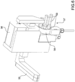
- the slide 35 supports a vertical vice 36 comprising a lower jaw 37 and an upper jaw 38 perpendicular to the direction 15.
- the jaw 37 comprises a flat plate 39, which is made of a substantially rigid material, for example a plastic or a metal material, is limited by an upper face 40 which is substantially horizontal and perpendicular to the direction 15, and is provided with a plurality of pneumatic nozzles 41 of known type fed with pressurized air by a pneumatic circuit (not shown) obtained through the plate 39.
- a pneumatic circuit not shown
- Each nozzle 41 opens outwards in the area of the face 40, and is configured to generate an air jet at least partially parallel to the face 40 so as to remove chips and/or machining scraps generated by the unit 22 and by devices 28, 29, 30 in the direction 10.
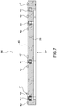
- the jaw 37 furthermore comprises a plurality of supporting strips 42 substantially parallel to one another, which extend in the direction 10, are housed in respective cavities formed on the face 40, and project upwards from the plate 39 to define a support plane P parallel to the face 40.
- the strips 42 are made of a deformable material, for example a polyurethane material, configured to deform, absorb chips and/or processing scraps trapped between the section bars 2 and the strips 42, and prevent the formation of scratches and/or grooves on the faces of the section bars 2 arranged in contact with the jaw 37.
- a deformable material for example a polyurethane material
- the jaw 38 comprises a vertical slide 43, which is coupled in a sliding manner to a vertical upright 44 projecting upwards from the slide 35 in the direction 15, and supports a locking plate 45 substantially L-shaped.
- the plate 45 is moved by the slide 43 in the direction 15 between a clamping position of the section bar 2 against the jaw 37 and a release position, and is, moreover, coupled in a sliding manner to the slide 43 to perform, with respect to the slide 43, straight movements in the direction 10.
- the plate 45 is moved in the direction 10 by a driving device 46 comprising a fork 47, which is mounted at an upper end of the upright 44 with its concavity facing downward, and is slidably coupled to the upright 44 to perform, with respect to the upright 44, rectilinear movements in the direction 10 under the thrust of an actuator cylinder 48.
- a driving device 46 comprising a fork 47, which is mounted at an upper end of the upright 44 with its concavity facing downward, and is slidably coupled to the upright 44 to perform, with respect to the upright 44, rectilinear movements in the direction 10 under the thrust of an actuator cylinder 48.
- the cylinder 48 cooperates with an end-of-stroke device 49 comprising a rotating disk 50, which is coupled in a rotatable manner to the upright 44 to rotate intermittently, with respect to the upright 44, around a rotation axis parallel to the direction 10, and has a plurality of end-of-stroke pins 51, which are uniformly distributed around the rotation axis of the disc 50, protrude from the disc 50 in the direction 10, and have different lengths from one another in the direction 10.
- an end-of-stroke device 49 comprising a rotating disk 50, which is coupled in a rotatable manner to the upright 44 to rotate intermittently, with respect to the upright 44, around a rotation axis parallel to the direction 10, and has a plurality of end-of-stroke pins 51, which are uniformly distributed around the rotation axis of the disc 50, protrude from the disc 50 in the direction 10, and have different lengths from one another in the direction 10.
- the plate 45 is raised in the direction 15 by the slide 43 so as to engage the fork 47; the fork 47 is moved in the direction 10 to selectively control the position of the plate 45 according to the configuration of the section bar 2 being machined ( Figures 4 and 5 ); and the slide 43 is lowered to disengage the plate 45 from the fork 47.
- the plate 45 is releasably locked on the slide 43 in the direction 10 by means of a ball locking device not shown.
- the slide 35 supports, furthermore, a horizontal vice 52 comprising a fixed jaw 53 and a jaw 54 movable in the direction 10 between a clamping position and a release position to clamp and release the section bars 2.
- the jaw 53 extends perpendicularly to the direction 10, is completely equivalent to the jaw 37, and cooperates with a lateral pad 55 mounted alongside the jaw 53.
- the pad 55 extends in the direction 4, and is movable in the direction 10 between an operating position, in which the pad 55 is arranged substantially in contact with the section bar 2 to stabilize the clamping of the section bar 2 between the jaws 53 and 54, and a rest position.
- the pad 55 is moved in the direction 10 by an actuator cylinder 56, which is mounted on the upright 44 parallel to direction 10, and cooperates with an end-of-stroke device 57.
- the device 57 comprises a rotating disk 58, which is mounted to rotate intermittently around a rotation axis parallel to the direction 10, and has a plurality of end-of-stroke pins 59, which are uniformly distributed around the rotation axis of the disk 58, protrude from the disk 58 in the direction 10, and have different lengths from one another in the direction 10.
- the actuator cylinder 56 and the limit-stroke device 57 are eliminated and replaced with an electric motor adapted to selectively control the position of the pad 55 in the direction 10.
- the device 34 comprises a horizontal slide 60 coupled in a sliding manner to the base 3 to perform, with respect to the base 3, rectilinear movements in the direction 4 independently of the slides 35 of the devices 31, 32, 33.
- the slide 60 supports a vertical vice 61, which is completely equivalent to the vices 36, and comprises a lower jaw 62 completely equivalent to the jaws 37 and an upper jaw 63 completely equivalent to the jaws 38.
- the jaw 63 is moved in the direction 10 by a driving device 64 which is completely equivalent to the device 46.
- the slide 60 is provided with a horizontal crosspiece 65, which extends in the direction 4, and supports a horizontal vice 66 comprising a first jaw 67, which is L-shaped, and is coupled in a sliding manner to the crosspiece 65 to perform straight movements along the crosspiece 65 in the direction 4.
- the jaw 67 comprises a plate 68 completely equivalent to the plates 39, and is provided with a pad 69, which defines part of the plate 68, is completely equivalent to the pads 55, and cooperates with an end-of-stroke device completely equivalent to the device 57.
- the vice 66 furthermore comprises a second jaw 70 comprising, in turn, a horizontal slide 71 coupled in a sliding manner to the jaw 67 to perform, with respect to the jaw 67 and under the thrust of an actuator cylinder 72, rectilinear movements in the direction 10, and a pad 73 coupled in a sliding manner to the slide 71 to move, with respect to the slide 71, in the direction 15 according to the shape of the section bar 2 being processed.
- a second jaw 70 comprising, in turn, a horizontal slide 71 coupled in a sliding manner to the jaw 67 to perform, with respect to the jaw 67 and under the thrust of an actuator cylinder 72, rectilinear movements in the direction 10, and a pad 73 coupled in a sliding manner to the slide 71 to move, with respect to the slide 71, in the direction 15 according to the shape of the section bar 2 being processed.
- the pad 73 is movable with respect to the jaw 67 in the direction 15.
- the pad 73 is locked in the direction 15 by a locking device 74 comprising a hooking plate 75 slidably coupled to the slide 71 to move, with respect to the slide 71, in the direction 4.
- the plate 75 is moved, and normally maintained, in a locking position, in which a toothed edge of the plate 75 engages a toothed edge of the pad 73, by at least one spring (not shown) interposed between the slide 71 and the plate 75.
- the vice 66 is movable along the crosspiece 65 between a first operating position ( Figure 8 ), in which the vice 66 is arranged in the machining station 16 and cooperates with the vice 61 and with the devices 31, 32, 33 to hold the section bars 2 during the processing thereof, and a second operating position ( Figure 9 ), in which the vice 66 is arranged in the unloading station 12 to release the section bars 2 that have just been processed onto the respective belt conveyor 13.
- the device 79 comprises a vertical slide 80 coupled to the slide 60 to move, with respect to the slide 60, in the direction 15; and an engagement fork 81, which extends in the direction 10, and is coupled to the slide 80 to move, with respect to the slide 80, in the direction 10 under the thrust of an actuator cylinder 82 mounted on the slide 80 parallel to the direction 10.
- the jaw 70 is moved to a clamping position of the section bars 2 by combining the action of the actuator cylinder 72 with the action of the actuator cylinder 82.
- each lower jaw 37, 62 of the vices 36, 61 is movable in the direction 15 to lower and release the section bars 2 onto at least one roller 83 of the respective device 31, 32, 33, 34.
- the jaws 37, 62 are fixed in the direction 15 and each roller 83 is movable in the direction 15 to disengage the section bars 2 from the respective jaw 37, 62.
Landscapes
- Engineering & Computer Science (AREA)
- Mechanical Engineering (AREA)
- Jigs For Machine Tools (AREA)
- Laminated Bodies (AREA)
- Crystals, And After-Treatments Of Crystals (AREA)
- Forging (AREA)
Applications Claiming Priority (1)
| Application Number | Priority Date | Filing Date | Title |
|---|---|---|---|
| IT102019000013017A IT201900013017A1 (it) | 2019-07-26 | 2019-07-26 | Macchina per la lavorazione di profilati di alluminio, leghe leggere, pvc o simili |
Publications (2)
| Publication Number | Publication Date |
|---|---|
| EP3769907A1 true EP3769907A1 (fr) | 2021-01-27 |
| EP3769907B1 EP3769907B1 (fr) | 2023-11-29 |
Family
ID=69173126
Family Applications (1)
| Application Number | Title | Priority Date | Filing Date |
|---|---|---|---|
| EP20187736.2A Active EP3769907B1 (fr) | 2019-07-26 | 2020-07-24 | Machine pour traiter des barres de section en aluminium, alliages légers, pvc ou similaire |
Country Status (2)
| Country | Link |
|---|---|
| EP (1) | EP3769907B1 (fr) |
| IT (1) | IT201900013017A1 (fr) |
Cited By (5)
| Publication number | Priority date | Publication date | Assignee | Title |
|---|---|---|---|---|
| CN114083016A (zh) * | 2021-11-30 | 2022-02-25 | 重庆海塑南邦铝业有限公司 | 铝合金门窗边框型材多工位工作线 |
| IT202100017204A1 (it) * | 2021-06-30 | 2022-12-30 | F O M Ind S R L | Centro di lavoro per la lavorazione di profilati, in particolare di alluminio, leghe leggere, pvc o simili |
| IT202100017210A1 (it) * | 2021-06-30 | 2022-12-30 | F O M Ind S R L | Centro di lavoro per la lavorazione di profilati, in particolare di alluminio, leghe leggere, pvc o simili |
| CN117086672A (zh) * | 2023-07-12 | 2023-11-21 | 湖北金彭车业有限公司 | 一种管材切割机上料装置 |
| CN117324993A (zh) * | 2023-09-14 | 2024-01-02 | 中亿丰罗普斯金材料科技股份有限公司 | 一种铝合金边框切割系统 |
Citations (3)
| Publication number | Priority date | Publication date | Assignee | Title |
|---|---|---|---|---|
| EP1555084A1 (fr) * | 2004-01-13 | 2005-07-20 | Mubea Systems, Société Anonyme | Machine-outil avec dispositifs de serrage coulissants en longueur avec des moyens moteurs propres |
| EP3175950A1 (fr) * | 2015-11-06 | 2017-06-07 | F.O.M. Industrie S.r.l. | Machine pour traiter des barres en aluminium, alliages légers, pvc ou similaire |
| EP3398713A1 (fr) * | 2017-05-02 | 2018-11-07 | F.O.M. Industrie S.r.l. | Procédé et machine pour traiter des barres, fabriquées en particulier en aluminium, alliages légers, pvc ou analogues |
-
2019
- 2019-07-26 IT IT102019000013017A patent/IT201900013017A1/it unknown
-
2020
- 2020-07-24 EP EP20187736.2A patent/EP3769907B1/fr active Active
Patent Citations (3)
| Publication number | Priority date | Publication date | Assignee | Title |
|---|---|---|---|---|
| EP1555084A1 (fr) * | 2004-01-13 | 2005-07-20 | Mubea Systems, Société Anonyme | Machine-outil avec dispositifs de serrage coulissants en longueur avec des moyens moteurs propres |
| EP3175950A1 (fr) * | 2015-11-06 | 2017-06-07 | F.O.M. Industrie S.r.l. | Machine pour traiter des barres en aluminium, alliages légers, pvc ou similaire |
| EP3398713A1 (fr) * | 2017-05-02 | 2018-11-07 | F.O.M. Industrie S.r.l. | Procédé et machine pour traiter des barres, fabriquées en particulier en aluminium, alliages légers, pvc ou analogues |
Cited By (7)
| Publication number | Priority date | Publication date | Assignee | Title |
|---|---|---|---|---|
| IT202100017204A1 (it) * | 2021-06-30 | 2022-12-30 | F O M Ind S R L | Centro di lavoro per la lavorazione di profilati, in particolare di alluminio, leghe leggere, pvc o simili |
| IT202100017210A1 (it) * | 2021-06-30 | 2022-12-30 | F O M Ind S R L | Centro di lavoro per la lavorazione di profilati, in particolare di alluminio, leghe leggere, pvc o simili |
| EP4112223A1 (fr) * | 2021-06-30 | 2023-01-04 | F.O.M. Industrie S.r.l. | Poste de travail pour traiter des barres de section, en particulier en aluminium, en alliages légers, en pvc ou analogues |
| CN114083016A (zh) * | 2021-11-30 | 2022-02-25 | 重庆海塑南邦铝业有限公司 | 铝合金门窗边框型材多工位工作线 |
| CN114083016B (zh) * | 2021-11-30 | 2022-12-27 | 重庆海塑南邦铝业有限公司 | 铝合金门窗边框型材多工位工作线 |
| CN117086672A (zh) * | 2023-07-12 | 2023-11-21 | 湖北金彭车业有限公司 | 一种管材切割机上料装置 |
| CN117324993A (zh) * | 2023-09-14 | 2024-01-02 | 中亿丰罗普斯金材料科技股份有限公司 | 一种铝合金边框切割系统 |
Also Published As
| Publication number | Publication date |
|---|---|
| IT201900013017A1 (it) | 2021-01-26 |
| EP3769907B1 (fr) | 2023-11-29 |
Similar Documents
| Publication | Publication Date | Title |
|---|---|---|
| EP3769907B1 (fr) | Machine pour traiter des barres de section en aluminium, alliages légers, pvc ou similaire | |
| EP3260234B1 (fr) | Machine de traitement de barres de section | |
| US9162334B2 (en) | A-axis machining apparatus | |
| CN114261028B (zh) | 硅棒切磨一体机 | |
| EP2366480B1 (fr) | Installation et procédé pour la fabrication de cadres pour portes ou pour fenêtres | |
| EP1810802A1 (fr) | Machine-outil | |
| KR101537757B1 (ko) | 피어싱 시스템 | |
| KR20110116998A (ko) | 레이저 가공기 및 그 전환 방법 | |
| JP2008183705A (ja) | ワークピース処理装置 | |
| CN114589352A (zh) | 用于锯开至少一个工件的方法和板分开设备 | |
| US20210069843A1 (en) | Autonomous processing station | |
| EP3175950B1 (fr) | Machine pour traiter des barres en aluminium, alliages légers, pvc ou similaire | |
| EP1922192B1 (fr) | Machine de sciage de panneaux | |
| EP1250213B1 (fr) | Machine-outil et procede d'usinage d'elements allonges, en particulier des elements profiles metalliques | |
| EP3398713B1 (fr) | Procédé et machine pour traiter des barres, fabriquées en particulier en aluminium, alliages légers, pvc ou analogues | |
| CN213470589U (zh) | 一种柱状产品端部去毛边用的去毛边装置 | |
| IT201900013038A1 (it) | Macchina per la lavorazione di profilati di alluminio, leghe leggere, pvc o simili | |
| CN106914790B (zh) | 加工定位装置、加工机床及加工方法 | |
| CN213470580U (zh) | 一种柱状产品端部去毛边用的去毛边机 | |
| CN210755536U (zh) | 一种高效率圆锯机 | |
| EP3533571B1 (fr) | Machine pour découper des panneaux en bois ou analogue | |
| CN110142455B (zh) | 一种高效率圆锯机 | |
| IT201900013029A1 (it) | Macchina per la lavorazione di profilati di alluminio, leghe leggere, pvc o simili | |
| EP4491325A1 (fr) | Machine pour couper et traiter des barres profilées, en particulier en aluminium, alliages légers, pvc ou similaires | |
| KR101897780B1 (ko) | 절단가공시스템 |
Legal Events
| Date | Code | Title | Description |
|---|---|---|---|
| PUAI | Public reference made under article 153(3) epc to a published international application that has entered the european phase |
Free format text: ORIGINAL CODE: 0009012 |
|
| STAA | Information on the status of an ep patent application or granted ep patent |
Free format text: STATUS: THE APPLICATION HAS BEEN PUBLISHED |
|
| AK | Designated contracting states |
Kind code of ref document: A1 Designated state(s): AL AT BE BG CH CY CZ DE DK EE ES FI FR GB GR HR HU IE IS IT LI LT LU LV MC MK MT NL NO PL PT RO RS SE SI SK SM TR |
|
| AX | Request for extension of the european patent |
Extension state: BA ME |
|
| STAA | Information on the status of an ep patent application or granted ep patent |
Free format text: STATUS: REQUEST FOR EXAMINATION WAS MADE |
|
| 17P | Request for examination filed |
Effective date: 20210726 |
|
| RBV | Designated contracting states (corrected) |
Designated state(s): AL AT BE BG CH CY CZ DE DK EE ES FI FR GB GR HR HU IE IS IT LI LT LU LV MC MK MT NL NO PL PT RO RS SE SI SK SM TR |
|
| GRAP | Despatch of communication of intention to grant a patent |
Free format text: ORIGINAL CODE: EPIDOSNIGR1 |
|
| STAA | Information on the status of an ep patent application or granted ep patent |
Free format text: STATUS: GRANT OF PATENT IS INTENDED |
|
| INTG | Intention to grant announced |
Effective date: 20230620 |
|
| GRAS | Grant fee paid |
Free format text: ORIGINAL CODE: EPIDOSNIGR3 |
|
| P01 | Opt-out of the competence of the unified patent court (upc) registered |
Effective date: 20230915 |
|
| GRAA | (expected) grant |
Free format text: ORIGINAL CODE: 0009210 |
|
| STAA | Information on the status of an ep patent application or granted ep patent |
Free format text: STATUS: THE PATENT HAS BEEN GRANTED |
|
| AK | Designated contracting states |
Kind code of ref document: B1 Designated state(s): AL AT BE BG CH CY CZ DE DK EE ES FI FR GB GR HR HU IE IS IT LI LT LU LV MC MK MT NL NO PL PT RO RS SE SI SK SM TR |
|
| REG | Reference to a national code |
Ref country code: GB Ref legal event code: FG4D |
|
| REG | Reference to a national code |
Ref country code: CH Ref legal event code: EP |
|
| REG | Reference to a national code |
Ref country code: DE Ref legal event code: R096 Ref document number: 602020021760 Country of ref document: DE |
|
| REG | Reference to a national code |
Ref country code: IE Ref legal event code: FG4D |
|
| REG | Reference to a national code |
Ref country code: LT Ref legal event code: MG9D |
|
| REG | Reference to a national code |
Ref country code: NL Ref legal event code: MP Effective date: 20231129 |
|
| PG25 | Lapsed in a contracting state [announced via postgrant information from national office to epo] |
Ref country code: GR Free format text: LAPSE BECAUSE OF FAILURE TO SUBMIT A TRANSLATION OF THE DESCRIPTION OR TO PAY THE FEE WITHIN THE PRESCRIBED TIME-LIMIT Effective date: 20240301 |
|
| PG25 | Lapsed in a contracting state [announced via postgrant information from national office to epo] |
Ref country code: IS Free format text: LAPSE BECAUSE OF FAILURE TO SUBMIT A TRANSLATION OF THE DESCRIPTION OR TO PAY THE FEE WITHIN THE PRESCRIBED TIME-LIMIT Effective date: 20240329 |
|
| PG25 | Lapsed in a contracting state [announced via postgrant information from national office to epo] |
Ref country code: LT Free format text: LAPSE BECAUSE OF FAILURE TO SUBMIT A TRANSLATION OF THE DESCRIPTION OR TO PAY THE FEE WITHIN THE PRESCRIBED TIME-LIMIT Effective date: 20231129 |
|
| PG25 | Lapsed in a contracting state [announced via postgrant information from national office to epo] |
Ref country code: ES Free format text: LAPSE BECAUSE OF FAILURE TO SUBMIT A TRANSLATION OF THE DESCRIPTION OR TO PAY THE FEE WITHIN THE PRESCRIBED TIME-LIMIT Effective date: 20231129 |
|
| PG25 | Lapsed in a contracting state [announced via postgrant information from national office to epo] |
Ref country code: LT Free format text: LAPSE BECAUSE OF FAILURE TO SUBMIT A TRANSLATION OF THE DESCRIPTION OR TO PAY THE FEE WITHIN THE PRESCRIBED TIME-LIMIT Effective date: 20231129 Ref country code: IS Free format text: LAPSE BECAUSE OF FAILURE TO SUBMIT A TRANSLATION OF THE DESCRIPTION OR TO PAY THE FEE WITHIN THE PRESCRIBED TIME-LIMIT Effective date: 20240329 Ref country code: GR Free format text: LAPSE BECAUSE OF FAILURE TO SUBMIT A TRANSLATION OF THE DESCRIPTION OR TO PAY THE FEE WITHIN THE PRESCRIBED TIME-LIMIT Effective date: 20240301 Ref country code: ES Free format text: LAPSE BECAUSE OF FAILURE TO SUBMIT A TRANSLATION OF THE DESCRIPTION OR TO PAY THE FEE WITHIN THE PRESCRIBED TIME-LIMIT Effective date: 20231129 Ref country code: BG Free format text: LAPSE BECAUSE OF FAILURE TO SUBMIT A TRANSLATION OF THE DESCRIPTION OR TO PAY THE FEE WITHIN THE PRESCRIBED TIME-LIMIT Effective date: 20240229 |
|
| REG | Reference to a national code |
Ref country code: AT Ref legal event code: MK05 Ref document number: 1635640 Country of ref document: AT Kind code of ref document: T Effective date: 20231129 |
|
| PG25 | Lapsed in a contracting state [announced via postgrant information from national office to epo] |
Ref country code: NL Free format text: LAPSE BECAUSE OF FAILURE TO SUBMIT A TRANSLATION OF THE DESCRIPTION OR TO PAY THE FEE WITHIN THE PRESCRIBED TIME-LIMIT Effective date: 20231129 |
|
| PG25 | Lapsed in a contracting state [announced via postgrant information from national office to epo] |
Ref country code: SE Free format text: LAPSE BECAUSE OF FAILURE TO SUBMIT A TRANSLATION OF THE DESCRIPTION OR TO PAY THE FEE WITHIN THE PRESCRIBED TIME-LIMIT Effective date: 20231129 Ref country code: RS Free format text: LAPSE BECAUSE OF FAILURE TO SUBMIT A TRANSLATION OF THE DESCRIPTION OR TO PAY THE FEE WITHIN THE PRESCRIBED TIME-LIMIT Effective date: 20231129 Ref country code: PL Free format text: LAPSE BECAUSE OF FAILURE TO SUBMIT A TRANSLATION OF THE DESCRIPTION OR TO PAY THE FEE WITHIN THE PRESCRIBED TIME-LIMIT Effective date: 20231129 Ref country code: NO Free format text: LAPSE BECAUSE OF FAILURE TO SUBMIT A TRANSLATION OF THE DESCRIPTION OR TO PAY THE FEE WITHIN THE PRESCRIBED TIME-LIMIT Effective date: 20240229 Ref country code: NL Free format text: LAPSE BECAUSE OF FAILURE TO SUBMIT A TRANSLATION OF THE DESCRIPTION OR TO PAY THE FEE WITHIN THE PRESCRIBED TIME-LIMIT Effective date: 20231129 Ref country code: LV Free format text: LAPSE BECAUSE OF FAILURE TO SUBMIT A TRANSLATION OF THE DESCRIPTION OR TO PAY THE FEE WITHIN THE PRESCRIBED TIME-LIMIT Effective date: 20231129 Ref country code: HR Free format text: LAPSE BECAUSE OF FAILURE TO SUBMIT A TRANSLATION OF THE DESCRIPTION OR TO PAY THE FEE WITHIN THE PRESCRIBED TIME-LIMIT Effective date: 20231129 |
|
| PG25 | Lapsed in a contracting state [announced via postgrant information from national office to epo] |
Ref country code: DK Free format text: LAPSE BECAUSE OF FAILURE TO SUBMIT A TRANSLATION OF THE DESCRIPTION OR TO PAY THE FEE WITHIN THE PRESCRIBED TIME-LIMIT Effective date: 20231129 |
|
| PG25 | Lapsed in a contracting state [announced via postgrant information from national office to epo] |
Ref country code: AT Free format text: LAPSE BECAUSE OF FAILURE TO SUBMIT A TRANSLATION OF THE DESCRIPTION OR TO PAY THE FEE WITHIN THE PRESCRIBED TIME-LIMIT Effective date: 20231129 Ref country code: CZ Free format text: LAPSE BECAUSE OF FAILURE TO SUBMIT A TRANSLATION OF THE DESCRIPTION OR TO PAY THE FEE WITHIN THE PRESCRIBED TIME-LIMIT Effective date: 20231129 |
|
| PG25 | Lapsed in a contracting state [announced via postgrant information from national office to epo] |
Ref country code: SK Free format text: LAPSE BECAUSE OF FAILURE TO SUBMIT A TRANSLATION OF THE DESCRIPTION OR TO PAY THE FEE WITHIN THE PRESCRIBED TIME-LIMIT Effective date: 20231129 |
|
| PG25 | Lapsed in a contracting state [announced via postgrant information from national office to epo] |
Ref country code: SM Free format text: LAPSE BECAUSE OF FAILURE TO SUBMIT A TRANSLATION OF THE DESCRIPTION OR TO PAY THE FEE WITHIN THE PRESCRIBED TIME-LIMIT Effective date: 20231129 Ref country code: SK Free format text: LAPSE BECAUSE OF FAILURE TO SUBMIT A TRANSLATION OF THE DESCRIPTION OR TO PAY THE FEE WITHIN THE PRESCRIBED TIME-LIMIT Effective date: 20231129 Ref country code: RO Free format text: LAPSE BECAUSE OF FAILURE TO SUBMIT A TRANSLATION OF THE DESCRIPTION OR TO PAY THE FEE WITHIN THE PRESCRIBED TIME-LIMIT Effective date: 20231129 Ref country code: EE Free format text: LAPSE BECAUSE OF FAILURE TO SUBMIT A TRANSLATION OF THE DESCRIPTION OR TO PAY THE FEE WITHIN THE PRESCRIBED TIME-LIMIT Effective date: 20231129 Ref country code: DK Free format text: LAPSE BECAUSE OF FAILURE TO SUBMIT A TRANSLATION OF THE DESCRIPTION OR TO PAY THE FEE WITHIN THE PRESCRIBED TIME-LIMIT Effective date: 20231129 Ref country code: CZ Free format text: LAPSE BECAUSE OF FAILURE TO SUBMIT A TRANSLATION OF THE DESCRIPTION OR TO PAY THE FEE WITHIN THE PRESCRIBED TIME-LIMIT Effective date: 20231129 Ref country code: AT Free format text: LAPSE BECAUSE OF FAILURE TO SUBMIT A TRANSLATION OF THE DESCRIPTION OR TO PAY THE FEE WITHIN THE PRESCRIBED TIME-LIMIT Effective date: 20231129 |
|
| PG25 | Lapsed in a contracting state [announced via postgrant information from national office to epo] |
Ref country code: PT Free format text: LAPSE BECAUSE OF FAILURE TO SUBMIT A TRANSLATION OF THE DESCRIPTION OR TO PAY THE FEE WITHIN THE PRESCRIBED TIME-LIMIT Effective date: 20240401 |
|
| PG25 | Lapsed in a contracting state [announced via postgrant information from national office to epo] |
Ref country code: PT Free format text: LAPSE BECAUSE OF FAILURE TO SUBMIT A TRANSLATION OF THE DESCRIPTION OR TO PAY THE FEE WITHIN THE PRESCRIBED TIME-LIMIT Effective date: 20240401 |
|
| REG | Reference to a national code |
Ref country code: DE Ref legal event code: R097 Ref document number: 602020021760 Country of ref document: DE |
|
| PLBE | No opposition filed within time limit |
Free format text: ORIGINAL CODE: 0009261 |
|
| STAA | Information on the status of an ep patent application or granted ep patent |
Free format text: STATUS: NO OPPOSITION FILED WITHIN TIME LIMIT |
|
| PG25 | Lapsed in a contracting state [announced via postgrant information from national office to epo] |
Ref country code: SI Free format text: LAPSE BECAUSE OF FAILURE TO SUBMIT A TRANSLATION OF THE DESCRIPTION OR TO PAY THE FEE WITHIN THE PRESCRIBED TIME-LIMIT Effective date: 20231129 |
|
| PG25 | Lapsed in a contracting state [announced via postgrant information from national office to epo] |
Ref country code: SI Free format text: LAPSE BECAUSE OF FAILURE TO SUBMIT A TRANSLATION OF THE DESCRIPTION OR TO PAY THE FEE WITHIN THE PRESCRIBED TIME-LIMIT Effective date: 20231129 |
|
| 26N | No opposition filed |
Effective date: 20240830 |
|
| PG25 | Lapsed in a contracting state [announced via postgrant information from national office to epo] |
Ref country code: MC Free format text: LAPSE BECAUSE OF FAILURE TO SUBMIT A TRANSLATION OF THE DESCRIPTION OR TO PAY THE FEE WITHIN THE PRESCRIBED TIME-LIMIT Effective date: 20231129 |
|
| REG | Reference to a national code |
Ref country code: CH Ref legal event code: PL |
|
| PG25 | Lapsed in a contracting state [announced via postgrant information from national office to epo] |
Ref country code: LU Free format text: LAPSE BECAUSE OF NON-PAYMENT OF DUE FEES Effective date: 20240724 |
|
| GBPC | Gb: european patent ceased through non-payment of renewal fee |
Effective date: 20240724 |
|
| PG25 | Lapsed in a contracting state [announced via postgrant information from national office to epo] |
Ref country code: LU Free format text: LAPSE BECAUSE OF NON-PAYMENT OF DUE FEES Effective date: 20240724 |
|
| PG25 | Lapsed in a contracting state [announced via postgrant information from national office to epo] |
Ref country code: BE Free format text: LAPSE BECAUSE OF NON-PAYMENT OF DUE FEES Effective date: 20240731 Ref country code: CH Free format text: LAPSE BECAUSE OF NON-PAYMENT OF DUE FEES Effective date: 20240731 |
|
| PG25 | Lapsed in a contracting state [announced via postgrant information from national office to epo] |
Ref country code: GB Free format text: LAPSE BECAUSE OF NON-PAYMENT OF DUE FEES Effective date: 20240724 |
|
| REG | Reference to a national code |
Ref country code: BE Ref legal event code: MM Effective date: 20240731 |
|
| PG25 | Lapsed in a contracting state [announced via postgrant information from national office to epo] |
Ref country code: IE Free format text: LAPSE BECAUSE OF NON-PAYMENT OF DUE FEES Effective date: 20240724 |
|
| PG25 | Lapsed in a contracting state [announced via postgrant information from national office to epo] |
Ref country code: FI Free format text: LAPSE BECAUSE OF FAILURE TO SUBMIT A TRANSLATION OF THE DESCRIPTION OR TO PAY THE FEE WITHIN THE PRESCRIBED TIME-LIMIT Effective date: 20231129 |
|
| PGFP | Annual fee paid to national office [announced via postgrant information from national office to epo] |
Ref country code: DE Payment date: 20250728 Year of fee payment: 6 |
|
| PGFP | Annual fee paid to national office [announced via postgrant information from national office to epo] |
Ref country code: TR Payment date: 20250707 Year of fee payment: 6 Ref country code: IT Payment date: 20250625 Year of fee payment: 6 |
|
| PGFP | Annual fee paid to national office [announced via postgrant information from national office to epo] |
Ref country code: FR Payment date: 20250725 Year of fee payment: 6 |
|
| PG25 | Lapsed in a contracting state [announced via postgrant information from national office to epo] |
Ref country code: CY Free format text: LAPSE BECAUSE OF FAILURE TO SUBMIT A TRANSLATION OF THE DESCRIPTION OR TO PAY THE FEE WITHIN THE PRESCRIBED TIME-LIMIT; INVALID AB INITIO Effective date: 20200724 |
|
| PG25 | Lapsed in a contracting state [announced via postgrant information from national office to epo] |
Ref country code: HU Free format text: LAPSE BECAUSE OF FAILURE TO SUBMIT A TRANSLATION OF THE DESCRIPTION OR TO PAY THE FEE WITHIN THE PRESCRIBED TIME-LIMIT; INVALID AB INITIO Effective date: 20200724 |