EP3769944B1 - Arbre d'entraînement composite selon un couple unidirectionnel dominant - Google Patents
Arbre d'entraînement composite selon un couple unidirectionnel dominant Download PDFInfo
- Publication number
- EP3769944B1 EP3769944B1 EP19213132.4A EP19213132A EP3769944B1 EP 3769944 B1 EP3769944 B1 EP 3769944B1 EP 19213132 A EP19213132 A EP 19213132A EP 3769944 B1 EP3769944 B1 EP 3769944B1
- Authority
- EP
- European Patent Office
- Prior art keywords
- fibers
- layers
- central axis
- oriented
- respect
- Prior art date
- Legal status (The legal status is an assumption and is not a legal conclusion. Google has not performed a legal analysis and makes no representation as to the accuracy of the status listed.)
- Active
Links
Images
Classifications
-
- F—MECHANICAL ENGINEERING; LIGHTING; HEATING; WEAPONS; BLASTING
- F16—ENGINEERING ELEMENTS AND UNITS; GENERAL MEASURES FOR PRODUCING AND MAINTAINING EFFECTIVE FUNCTIONING OF MACHINES OR INSTALLATIONS; THERMAL INSULATION IN GENERAL
- F16C—SHAFTS; FLEXIBLE SHAFTS; ELEMENTS OR CRANKSHAFT MECHANISMS; ROTARY BODIES OTHER THAN GEARING ELEMENTS; BEARINGS
- F16C3/00—Shafts; Axles; Cranks; Eccentrics
- F16C3/02—Shafts; Axles
- F16C3/026—Shafts made of fibre reinforced resin
-
- B—PERFORMING OPERATIONS; TRANSPORTING
- B29—WORKING OF PLASTICS; WORKING OF SUBSTANCES IN A PLASTIC STATE IN GENERAL
- B29C—SHAPING OR JOINING OF PLASTICS; SHAPING OF MATERIAL IN A PLASTIC STATE, NOT OTHERWISE PROVIDED FOR; AFTER-TREATMENT OF THE SHAPED PRODUCTS, e.g. REPAIRING
- B29C70/00—Shaping composites, i.e. plastics material comprising reinforcements, fillers or preformed parts, e.g. inserts
- B29C70/04—Shaping composites, i.e. plastics material comprising reinforcements, fillers or preformed parts, e.g. inserts comprising reinforcements only, e.g. self-reinforcing plastics
- B29C70/06—Fibrous reinforcements only
- B29C70/10—Fibrous reinforcements only characterised by the structure of fibrous reinforcements, e.g. hollow fibres
- B29C70/16—Fibrous reinforcements only characterised by the structure of fibrous reinforcements, e.g. hollow fibres using fibres of substantial or continuous length
- B29C70/20—Fibrous reinforcements only characterised by the structure of fibrous reinforcements, e.g. hollow fibres using fibres of substantial or continuous length oriented in a single direction, e.g. roofing or other parallel fibres
- B29C70/202—Fibrous reinforcements only characterised by the structure of fibrous reinforcements, e.g. hollow fibres using fibres of substantial or continuous length oriented in a single direction, e.g. roofing or other parallel fibres arranged in parallel planes or structures of fibres crossing at substantial angles, e.g. cross-moulding compound [XMC]
-
- B—PERFORMING OPERATIONS; TRANSPORTING
- B29—WORKING OF PLASTICS; WORKING OF SUBSTANCES IN A PLASTIC STATE IN GENERAL
- B29C—SHAPING OR JOINING OF PLASTICS; SHAPING OF MATERIAL IN A PLASTIC STATE, NOT OTHERWISE PROVIDED FOR; AFTER-TREATMENT OF THE SHAPED PRODUCTS, e.g. REPAIRING
- B29C70/00—Shaping composites, i.e. plastics material comprising reinforcements, fillers or preformed parts, e.g. inserts
- B29C70/04—Shaping composites, i.e. plastics material comprising reinforcements, fillers or preformed parts, e.g. inserts comprising reinforcements only, e.g. self-reinforcing plastics
- B29C70/06—Fibrous reinforcements only
- B29C70/10—Fibrous reinforcements only characterised by the structure of fibrous reinforcements, e.g. hollow fibres
- B29C70/16—Fibrous reinforcements only characterised by the structure of fibrous reinforcements, e.g. hollow fibres using fibres of substantial or continuous length
- B29C70/20—Fibrous reinforcements only characterised by the structure of fibrous reinforcements, e.g. hollow fibres using fibres of substantial or continuous length oriented in a single direction, e.g. roofing or other parallel fibres
- B29C70/205—Fibrous reinforcements only characterised by the structure of fibrous reinforcements, e.g. hollow fibres using fibres of substantial or continuous length oriented in a single direction, e.g. roofing or other parallel fibres the structure being shaped to form a three-dimensional configuration
- B29C70/207—Fibrous reinforcements only characterised by the structure of fibrous reinforcements, e.g. hollow fibres using fibres of substantial or continuous length oriented in a single direction, e.g. roofing or other parallel fibres the structure being shaped to form a three-dimensional configuration arranged in parallel planes of fibres crossing at substantial angles
-
- B—PERFORMING OPERATIONS; TRANSPORTING
- B29—WORKING OF PLASTICS; WORKING OF SUBSTANCES IN A PLASTIC STATE IN GENERAL
- B29C—SHAPING OR JOINING OF PLASTICS; SHAPING OF MATERIAL IN A PLASTIC STATE, NOT OTHERWISE PROVIDED FOR; AFTER-TREATMENT OF THE SHAPED PRODUCTS, e.g. REPAIRING
- B29C70/00—Shaping composites, i.e. plastics material comprising reinforcements, fillers or preformed parts, e.g. inserts
- B29C70/04—Shaping composites, i.e. plastics material comprising reinforcements, fillers or preformed parts, e.g. inserts comprising reinforcements only, e.g. self-reinforcing plastics
- B29C70/28—Shaping operations therefor
- B29C70/30—Shaping by lay-up, i.e. applying fibres, tape or broadsheet on a mould, former or core; Shaping by spray-up, i.e. spraying of fibres on a mould, former or core
-
- B—PERFORMING OPERATIONS; TRANSPORTING
- B29—WORKING OF PLASTICS; WORKING OF SUBSTANCES IN A PLASTIC STATE IN GENERAL
- B29C—SHAPING OR JOINING OF PLASTICS; SHAPING OF MATERIAL IN A PLASTIC STATE, NOT OTHERWISE PROVIDED FOR; AFTER-TREATMENT OF THE SHAPED PRODUCTS, e.g. REPAIRING
- B29C70/00—Shaping composites, i.e. plastics material comprising reinforcements, fillers or preformed parts, e.g. inserts
- B29C70/04—Shaping composites, i.e. plastics material comprising reinforcements, fillers or preformed parts, e.g. inserts comprising reinforcements only, e.g. self-reinforcing plastics
- B29C70/28—Shaping operations therefor
- B29C70/30—Shaping by lay-up, i.e. applying fibres, tape or broadsheet on a mould, former or core; Shaping by spray-up, i.e. spraying of fibres on a mould, former or core
- B29C70/32—Shaping by lay-up, i.e. applying fibres, tape or broadsheet on a mould, former or core; Shaping by spray-up, i.e. spraying of fibres on a mould, former or core on a rotating mould, former or core
-
- B—PERFORMING OPERATIONS; TRANSPORTING
- B29—WORKING OF PLASTICS; WORKING OF SUBSTANCES IN A PLASTIC STATE IN GENERAL
- B29C—SHAPING OR JOINING OF PLASTICS; SHAPING OF MATERIAL IN A PLASTIC STATE, NOT OTHERWISE PROVIDED FOR; AFTER-TREATMENT OF THE SHAPED PRODUCTS, e.g. REPAIRING
- B29C70/00—Shaping composites, i.e. plastics material comprising reinforcements, fillers or preformed parts, e.g. inserts
- B29C70/88—Shaping composites, i.e. plastics material comprising reinforcements, fillers or preformed parts, e.g. inserts characterised primarily by possessing specific properties, e.g. electrically conductive or locally reinforced
- B29C70/887—Shaping composites, i.e. plastics material comprising reinforcements, fillers or preformed parts, e.g. inserts characterised primarily by possessing specific properties, e.g. electrically conductive or locally reinforced locally reinforced, e.g. by fillers
-
- B—PERFORMING OPERATIONS; TRANSPORTING
- B29—WORKING OF PLASTICS; WORKING OF SUBSTANCES IN A PLASTIC STATE IN GENERAL
- B29L—INDEXING SCHEME ASSOCIATED WITH SUBCLASS B29C, RELATING TO PARTICULAR ARTICLES
- B29L2031/00—Other particular articles
- B29L2031/748—Machines or parts thereof not otherwise provided for
- B29L2031/75—Shafts
Definitions
- the present invention relates generally to composite shafts, and more particularly, to drive shafts used for load transfer.
- Torsional load is usually the primary load component applied to drive shafts.
- Certain applications of shafts such as, for example, in helicopters, cause them to experience torque primarily in one direction. Torque generates in-plane shear stresses in the shaft walls, which can be decoupled into tensile stresses in one direction and compressive stresses in another direction.
- Conventional composite drive shafts have symmetrical layups that are consequently often heavily loaded with respect to one stress path (e.g., compression), and under-loaded with respect to another (e.g., tensile) during ordinary operation. Under such conditions, composite drive shafts can be prone to failures primarily along compressive or tensile load paths, depending on the material properties of the composite shaft itself.
- EP 1458554 relates to a drive shaft extending along a central axis and being configured to operate under dominant unidirectional torsional load, the drive shaft comprising: an asymmetrically-structured composite body configured to have a greater torque-carrying capability in a first torsional direction than in a second torsional direction, the second torsional direction being opposite the first torsional direction; wherein the asymmetrically-structured composite body comprises: a first plurality of fibers oriented in a first direction at a first angle with respect to the central axis; and a second plurality of fibers oriented in a second direction at a second angle with respect to the central axis, wherein the first and second directions are different; and wherein the first plurality of fibers and the second plurality of fibers provide a greater torque-carrying capability in the first torsional direction than in the second torsional direction; wherein the first plurality of fibers comprises more fibers than the second plurality of fibers; wherein fibers of the first pluralit
- a drive shaft extends along a central axis and is configured to operate under dominant unidirectional torsional load.
- the drive shaft is provided in claim 1 and comprises an asymmetrically-structured composite body.
- the asymmetrically-structured composite body is configured to have a greater torque-carrying capability in a first torsional direction than in a second torsional direction opposite the first torsional direction.
- a method of manufacturing a composite drive shaft includes orienting a first plurality of layers in a first direction at a first angle with respect to a central axis of the drive shaft and orienting a second plurality of layers in a second direction that is different from the first direction at a second angle with respect to the central axis.
- the first plurality of layers provides a first total thickness and is comprised of a first plurality of fibers oriented in the first direction.
- the second plurality of layers provides a second total thickness and is comprised of a second plurality of fibers oriented in the second direction.
- the first plurality of fibers comprises more fibers than the second plurality of fibers.
- the first plurality of layers and the second plurality of layers are impregnated with a polymer matrix.
- Torsional load is a primary load component applied to drive shafts.
- This torsional load causes in-plane shear stresses in the walls of the shaft. These shear stresses can be decoupled into mutually orthogonal compressive stresses and tensile stresses.
- There is a broad class of drive shaft applications for example, in rotorcraft, where orientation of the torque load is consistently applied in one orientation, i.e., these shafts are under a dominant unidirectional torque. For these applications, orientations of the compressive and tensile stresses are also consistent, and this understanding is used for drive shaft enhancement as described below.
- Fiber-based composites In the case of a dominant unidirectional load, the design is driven by corresponding compressive stresses and tensile stresses and their paths or directions, respectively. Fiber-based composites generally have greater tensile strength than compressive strength along the fiber direction. Thus, if a composite drive shaft is consistently under a dominant unidirectional load, more fiber-reinforced layers can be placed in the compressive stress direction than in the tensile stress direction.
- This asymmetric design gives the shaft a greater torque-bearing capability in one torsional direction than in the opposite torsional direction, meaning that when the shaft is attached to a load, it will be able to bear a greater torsional load in one torsional direction about the central axis than in the opposite torsional direction. Because the shaft is under a dominant unidirectional load, it can be designed to suit this unidirectional load without also needing to bear a similar load in the opposite direction.
- the asymmetric design can unify the risks of the shaft's structural failures under both compressive and tensile stresses.
- Such an asymmetric design provides advantages over conventional symmetric designs where the numbers of fiber-reinforced layers in the compressive stress and tensile stress directions are equal. This asymmetric design increases the efficiency of the composite drive shaft through increased bearing ability and/or reduced weight.
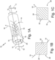
- FIG. 1A is a perspective view of composite drive shaft 10 aligned along central axis Z and radial line R, and experiencing dominant torque T in first torque direction 12 and second torque direction 13.
- Dominant torque T in first torque direction 12 and second torque direction 13 generates compressive stresses and tensile stresses along the length of composite drive shaft 10. These compressive stresses are oriented in a consistent alignment along the length of composite shaft 10, defined herein as compressive stress direction 14.
- the tensile stresses are similarly oriented in a consistent alignment along the length of composite shaft 10, defined herein as tensile stress direction 16.
- the angle + ⁇ of compressive stress direction 14 can be oriented in a broader range around +45 degrees, for example, between +35 degrees and +55 degrees with respect to central axis Z.
- the angle - ⁇ of tensile stress direction 16 can be oriented in a broader range around -45 degrees, for example between -35 degrees and -55 degrees with respect to central axis Z.
- composite drive shaft 10 is comprised of composite material 18, which is made up of layers 20 of fibers 22 (shown in FIGS. 1B-1C ) and polymer matrix 24 (shown in FIGS. 1B-1C ).
- Layers 20 include a plurality of first layers 26 with fiber orientation along compressive stress direction 14 (fiber orientation shown in FIG. 1B ) and a plurality of second layers 28 with fiber orientation along tensile stress direction 16 (fiber orientation shown in FIG. 1C ).
- Fibers 22 can be impregnated with polymer matrix 24 so as to become embedded within it and form layers 20.
- Fibers 22 can be carbon fibers, glass fibers, organic fibers, or combinations thereof, or another suitable material as known in the art.
- Polymer matrix 24 can be a thermoset polymer, a thermoplastic polymer, or another suitable matrix material.
- FIG. 1B illustrates representative first layer 26 with fiber orientation along compressive stress direction 14 within composite drive shaft 10 of FIG. 1A .
- fibers 22 in each first layer 26 are oriented at +45 degrees with respect to central axis Z and arranged within polymer matrix 24.
- FIG. 1C illustrates representative second layer 28 with fiber orientation along tensile stress direction 16 within composite drive shaft 10 of FIG. 1A .
- fibers 22 in each second layer 28 are oriented at -45 degrees with respect to central axis Z and arranged within polymer matrix 24.
- first layers 26 experience compressive stress ⁇ c in compressive stress direction 14, and second layers 28 experience tensile stress ⁇ t in first tensile stress direction 16.
- fibers 22 are generally weaker under compressive stress ⁇ c than under tensile stress ⁇ t . This causes first layers 26 to be weaker than second layers 28 in the case of symmetric composite layups, i.e., designs with equal number of first layers 26 and second layers 28.
- first layers 26 with fibers substantially oriented along compression stress direction 14
- second layers 28 with fibers substantially oriented along tensile stress direction 16
- the roles of first layers 26 and second layers 28 i.e. compressive vs. tensile
- first torque direction 12 and second torque direction 13 were reversed.
- the present structure can produce aggregate strength sufficient to efficiently handle dominant torque T, without needing to also withstand stresses corresponding to the torque in the opposite direction.
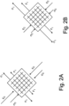
- FIGS. 2A and 2B schematically show stresses in the fiber directions, namely, compressive stresses, ⁇ c , and tensile stresses, ⁇ t , along with introduced values of failure susceptibility F.
- the failure susceptibility is defined as a ratio of a stress to a corresponding strength, i.e., as F c in case of layer-wise compressive strength S c and Ft in case of layer-wise tensile strength St.
- FIG. 2A schematically depicts stresses and failure susceptibility for a conventional symmetric design, where aggregate numbers of first layers 26 and second layers 28 are equal.
- stresses ⁇ c and ⁇ t are equal, but failure susceptibilities F c and F t are not equal, due to differences in compression and tensile strengths of layers 20. Therefore, for this conventional design, if compressive strength S c is lower than tensile strength St, compressive failure susceptibility F c is higher than tensile susceptibility Ft, making first layers 26 over-loaded and second layers 28 under-loaded.
- FIG. 2B schematically depicts stresses and failure susceptibility for an asymmetric composite drive shaft design, where aggregate numbers of first layers 26 and second layers 28 are not equal.
- stresses ⁇ c and ⁇ t are not equal, but failure susceptibilities F c and F t are equal or almost equal. Therefore, for the asymmetric design, even if compressive strength S c is lower than the tensile strength St, compressive failure susceptibility F c and tensile susceptibility F t are practically the same, making risks of failure in first layers 26 and second layers 28 very close and ideally equal.
- compressive failure susceptibility F c in compressive stress direction 14 is equal to tensile failure susceptibility Ft in tensile stress direction 16 because tensile stress ⁇ t has been scaled up by a factor of tensile strength St over compressive strength S c .
- This can be accomplished by reducing the total number of second layers 28 with fibers oriented in tensile stress direction 16 and/or increasing the total number of first layers 26 with fibers oriented in compressive stress direction 14, such that either first layers 26 outnumber second layers 28, or the total thickness of first layers 26 is greater than the total thickness of second layers 28, by a factor of layer-wise tensile strength over layer-wise compressive strength.
- the factor of outnumbering of first layers 26 in comparison with second layers 28 can be defined according to other potential failure mechanisms or their combinations.
- failure mechanisms for example, buckling of the shaft wall or buckling of individual layers due to interlaminar debonding can be considered in addition to the strength limits of layers in the fiber direction.
- the total number of first layers 26 is greater than the total number of second layers 28, or the total thickness of first layers 26 is greater than the total thickness of second layers 28 by a factor of at least 1.05. While discussed in terms of the number or thickness of first layers 26 and second layers 28, the increase or decrease in the number of first layers 26 and second layers 28 or total thickness of first layers 26 and second layers 28 represents an increase or decrease in the number of fibers oriented in compressive stress direction 14 and tensile stress direction 16. As such, the disclosed embodiments having more first layers 26 than second layers 28 or greater thickness of first layers 26 than thickness of second layers 28 have more fibers arranged in compressive stress direction 14 than are arranged in tensile stress direction 16.
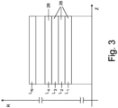
- layers L 1 , L 2 , and L 3 are first layers 26 with fiber orientation along compressive stress direction 14, and layer L 4 is second layer 28 with fiber orientation along tensile stress direction 16.
- First layers 26 experience compressive stress ⁇ c in compressive stress direction 14, and second layers 28 experience tensile stress ⁇ t in tensile stress direction 16.
- first layers 26 with fibers oriented in compressive stress direction 14 are weaker than second layers 28 with fibers oriented in tensile stress direction 16, there is a greater number of first layers 26 than second layers 28. Decreasing the total number of second layers 28 increases tensile stress ⁇ t on each individual second layer 28.
- first layers 26 and second layers 28 within composite drive shaft 10 can be varied.
- first layers 26 and second layers 28 could be arranged in a blocked design where some or all of first layers 26 are arranged together and some or all of second layers 28 are arranged together.
- Layers L 1 -L 4 in FIG. 3 illustrate a simple blocked design where layers L 1 , L 2 , and L 3 are all first layers 26 with fibers arranged in compressive stress direction 14 and are arranged together separately from L 4 , an individual second layer 28 with fibers arranged in tensile stress direction 16.
- second layers 28 could be interspersed within first layers 26 to create a pattern of alternating first layers 26 and second layers 28 or alternating blocks of first layers 26 and second layers 28.
- composite drive shaft 10 can include additional layers that are designed to handle other stresses within composite drive shaft 10 due to additional load components, such as for example, bending or/and axial loads, and/or potential failure mechanisms, such as for example, buckling of shaft walls. This can be done by, for example, orienting fibers 22 at 90 degrees to minimize the risk of buckling, or 0 degrees to limit stresses due to bending or axial loads. Additional layers can also be designed at other angles with respect to central axis Z. Additional layers in these alternative orientations can require that the angles of fibers 22 in first layers 26 and second layers 28 be adjusted to account for reinforcement provided by these additional layers.
- a composite drive shaft under unidirectional torque has a load applied in a single known direction.
- Using an asymmetric layup allows the composite drive shaft to be tailored to differing compressive and tensile stresses it experiences in different directions. This increases the efficiency of the composite drive shaft at bearing expected loads, reducing the required mass by unifying the risks of the shaft's structural failure under both compressive and tensile stresses.
- any relative terms or terms of degree used herein such as “substantially”, “essentially”, “generally”, “approximately” and the like, should be interpreted in accordance with and subject to any applicable definitions or limits expressly stated herein.
- any relative terms or terms of degree used herein should be interpreted to broadly encompass any relevant disclosed embodiments as well as such ranges or variations as would be understood by a person of ordinary skill in the art in view of the entirety of the present disclosure, such as to encompass ordinary manufacturing tolerance variations, incidental alignment variations, transient alignment or shape variations induced by thermal, rotational or vibrational operational conditions, and the like.
- any relative terms or terms of degree used herein should be interpreted to encompass a range that expressly includes the designated quality, characteristic, parameter or value, without variation, as if no qualifying relative term or term of degree were utilized in the given disclosure or recitation.
- polymer matrix can be comprised of a thermoset polymer or a thermoplastic polymer.
- the fibers can be fibers selected from a group consisting of carbon fibers, glass fibers, organic fibers, and combinations thereof.
- drive shaft can further include layers which are oriented in a third direction at a third angle with respect to the central axis.
- the third angle can be different than the first and second angles.
- first angle can be oriented between +35 degrees and +55 degrees with respect to the central axis
- second angle can be oriented between -35 degrees and -55 degrees with respect to the central axis
- a further example of any of the foregoing drive shafts wherein the first angle can be oriented +45 degrees with respect to the central axis, and the second angle can be oriented -45 degrees with respect to the central axis.
- polymer matrix can be comprised of a thermoset polymer or a thermoplastic polymer.
- the fibers can be fibers selected from a group consisting of carbon fibers, glass fibers, organic fibers, and combinations thereof.
- a further example of any of the foregoing methods which can include orienting layers in a third direction and at a third angle with respect to a central axis of the drive shaft.
- the third angle can be different than the first and second angles.
- first angle can be oriented between +35 degrees and +55 degrees with respect to the central axis and the second angle can be oriented between -35 degrees and -55 degrees with respect to the central axis.
- first angle can be oriented +45 degrees with respect to the central axis and the second angle can be oriented -45 degrees with respect to the central axis.
Landscapes
- Engineering & Computer Science (AREA)
- Mechanical Engineering (AREA)
- Chemical & Material Sciences (AREA)
- Composite Materials (AREA)
- General Engineering & Computer Science (AREA)
- Ocean & Marine Engineering (AREA)
- Textile Engineering (AREA)
- Shafts, Cranks, Connecting Bars, And Related Bearings (AREA)
Claims (10)
- Arbre d'entraînement (10) s'étendant le long d'un axe central et étant configuré pour fonctionner sous une charge de torsion unidirectionnelle dominante, l'arbre d'entraînement comprenant :un corps composite à structure asymétrique configuré pour avoir une plus grande capacité de transport de couple dans une première direction de torsion que dans une seconde direction de torsion, la seconde direction de torsion étant opposée à la première direction de torsion ;dans lequel le corps composite à structure asymétrique comprend :une première pluralité de fibres (26) orientées dans une première direction selon un premier angle par rapport à l'axe central ; etune seconde pluralité de fibres (28) orientées dans une deuxième direction selon un deuxième angle par rapport à l'axe central, dans lequel les première et deuxième directions sont différentes ; etdans lequel la première pluralité de fibres et la deuxième pluralité de fibres fournissent une plus grande capacité de transport de couple dans la première direction de torsion que dans la seconde direction de torsion ;dans lequel la première pluralité de fibres (26) comprend plus de fibres que la deuxième pluralité de fibres (28) ;dans lequel des fibres de la première pluralité de fibres (26) sont noyées dans une matrice polymère et agencées dans une première pluralité de couches et dans lequel des fibres de la deuxième pluralité de fibres (28) sont noyées dans une matrice polymère et agencées dans une deuxième pluralité de couches ;dans lequel la première pluralité de fibres est sensiblement orientée dans une direction de contrainte de compression lorsqu'elle fonctionne sous la charge de torsion unidirectionnelle dominante et dans lequel la deuxième pluralité de fibres est sensiblement orientée dans une direction de contrainte de traction lorsqu'elle fonctionne sous la charge de torsion unidirectionnelle dominante ;dans lequel la première pluralité de couches est plus nombreuse que la deuxième pluralité de couches d'au moins un facteur de 1,05 ; et/oudans lequel une épaisseur totale de la première pluralité de couches est supérieure à une épaisseur totale de la deuxième pluralité de couches d'au moins un facteur de 1,05.
- Arbre d'entraînement selon la revendication 1, dans lequel la matrice polymère comprend un polymère thermodurci ou un polymère thermoplastique.
- Arbre d'entraînement selon la revendication 1, dans lequel la première pluralité de fibres et la deuxième pluralité de fibres comprennent des fibres choisies dans un groupe composé de fibres de carbone, de fibres de verre, de fibres organiques et de combinaisons de celles-ci.
- Arbre d'entraînement selon la revendication 1, dans lequel l'arbre d'entraînement comprend également une troisième pluralité de fibres orientées dans une troisième direction selon un troisième angle par rapport à l'axe central différent des premier et deuxième angles.
- Arbre de transmission selon la revendication 1, dans lequel le premier angle est orienté entre +35 degrés et +55 degrés par rapport à l'axe central et le deuxième angle est orienté entre -35 degrés et -55 degrés par rapport à l'axe central, et de manière davantage préférée, dans lequel le premier angle est orienté à +45 degrés par rapport à l'axe central et le deuxième angle est orienté à -45 degrés par rapport à l'axe central.
- Procédé de fabrication d'un arbre d'entraînement composite, le procédé comprenant :l'orientation d'une première pluralité de fibres dans une première direction selon un premier angle par rapport à un axe central de l'arbre d'entraînement, la première pluralité de fibres étant agencée en une première pluralité de couches pour fournir une première épaisseur totale ;l'orientation d'une deuxième pluralité de fibres dans une deuxième direction qui est différente de la première direction et selon un deuxième angle par rapport à l'axe central, la deuxième pluralité de fibres étant agencée en une deuxième pluralité de couches pour fournir une seconde épaisseur totale ; dans lequel la première pluralité de fibres comprend plus de fibres que la deuxième pluralité de fibres ;dans lequel la première pluralité de couches est plus nombreuse que la deuxième pluralité de couches d'au moins un facteur de 1,05 ; et/oudans lequel une épaisseur totale de la première pluralité de couches est supérieure à une épaisseur totale de la deuxième pluralité de couches d'au moins un facteur de 1,05 ;l'imprégnation de la première pluralité de fibres et de la deuxième pluralité de fibres avec une matrice polymère ;dans lequel la première pluralité de fibres et la deuxième pluralité de fibres fournissent une plus grande capacité de transport de couple dans la première direction de torsion que dans la seconde direction de torsion ; etdans lequel la première pluralité de fibres est sensiblement orientée dans une direction de contrainte de compression lorsqu'elle fonctionne sous la charge de torsion unidirectionnelle dominante et dans lequel la deuxième pluralité de fibres est sensiblement orientée dans une direction de contrainte de traction lorsqu'elle fonctionne sous la charge de torsion unidirectionnelle dominante.
- Procédé selon la revendication 6, dans lequel la matrice polymère comprend un polymère thermodurci ou un polymère thermoplastique.
- Procédé selon l'une quelconque des revendications 6 ou 7, dans lequel la première pluralité de fibres et la deuxième pluralité de fibres sont constituées de fibres choisies dans un groupe composé de fibres de carbone, de fibres de verre, de fibres organiques et de combinaisons de celles-ci.
- Procédé selon l'une quelconque des revendications 6 à 8, constitué également de l'orientation d'une troisième pluralité de couches dans une troisième direction selon un troisième angle par rapport à l'axe central différent des premier et deuxième angles.
- Procédé selon l'une quelconque des revendications 6 à 9, dans lequel le premier angle est orienté entre +35 degrés et +55 degrés par rapport à l'axe central et le deuxième angle est orienté entre -35 degrés et -55 degrés par rapport à l'axe central, et de manière davantage préférée, dans lequel le premier angle est orienté à +45 degrés par rapport à l'axe central et le deuxième angle est orienté à -45 degrés par rapport à l'axe central.
Applications Claiming Priority (1)
| Application Number | Priority Date | Filing Date | Title |
|---|---|---|---|
| US16/518,418 US11773896B2 (en) | 2019-07-22 | 2019-07-22 | Composite drive shaft under dominant unidirectional torque |
Publications (2)
| Publication Number | Publication Date |
|---|---|
| EP3769944A1 EP3769944A1 (fr) | 2021-01-27 |
| EP3769944B1 true EP3769944B1 (fr) | 2024-10-02 |
Family
ID=68766593
Family Applications (1)
| Application Number | Title | Priority Date | Filing Date |
|---|---|---|---|
| EP19213132.4A Active EP3769944B1 (fr) | 2019-07-22 | 2019-12-03 | Arbre d'entraînement composite selon un couple unidirectionnel dominant |
Country Status (2)
| Country | Link |
|---|---|
| US (1) | US11773896B2 (fr) |
| EP (1) | EP3769944B1 (fr) |
Citations (1)
| Publication number | Priority date | Publication date | Assignee | Title |
|---|---|---|---|---|
| EP1458554B1 (fr) * | 2001-10-31 | 2009-12-09 | Saab Ab | Dispositif et procede concernant un arbre d'entrainement |
Family Cites Families (33)
| Publication number | Priority date | Publication date | Assignee | Title |
|---|---|---|---|---|
| US3651661A (en) | 1970-02-02 | 1972-03-28 | United Aircraft Corp | Composite shaft with integral end flange |
| US3691000A (en) * | 1971-03-10 | 1972-09-12 | Celanese Corp | Glass fiber reinforced composite article exhibiting enhanced longitudinal tensile and compressive moduli |
| US4089190A (en) * | 1976-04-14 | 1978-05-16 | Union Carbide Corporation | Carbon fiber drive shaft |
| US4157181A (en) * | 1976-05-07 | 1979-06-05 | Fansteel Inc. | Graphite fiber tapered shafts |
| US4186696A (en) * | 1978-01-31 | 1980-02-05 | Exxon Research & Engineering Co. | Push rods and the like |
| GB2026651B (en) * | 1978-07-17 | 1983-02-02 | Gkn Transmissions Ltd | Shafts |
| WO1980002186A1 (fr) * | 1979-04-02 | 1980-10-16 | Inst Mat I Mek An Azerbaidzhan | Tuyau souple |
| US4238539A (en) | 1979-05-29 | 1980-12-09 | Celanese Corporation | Fiber reinforced composite shaft with metallic connector sleeves mounted by a knurl interlock |
| US4259382A (en) * | 1979-05-29 | 1981-03-31 | Celanese Corporation | Fiber reinforced composite shaft with metal connector sleeves secured by adhesive |
| US4248062A (en) * | 1979-10-05 | 1981-02-03 | Shakespeare Company | Drive shaft assembly and method for making same |
| GB2070193A (en) * | 1980-02-21 | 1981-09-03 | Brd Co Ltd | Fibre reinforced composite shafts |
| EP0145810A1 (fr) * | 1983-12-20 | 1985-06-26 | Joachim Dr. Schnell | Arbre élastique |
| DE3432907A1 (de) * | 1984-09-07 | 1986-06-19 | Alfred Prof. Dr.-Ing. 3524 Immenhausen Puck | Verfahren zur erzielung hoher rissbildungsgrenzen in einem langgestreckten hohlkoerper |
| US4863416A (en) | 1985-08-16 | 1989-09-05 | Lord Corporation | Misalignment accommodating composite shaft |
| GB2231638B (en) | 1986-04-30 | 1991-02-20 | Dana Corp | Manufacture of composite vehicle drive shafts |
| US4716072A (en) * | 1986-12-29 | 1987-12-29 | General Electric Company | Multilayer composite structure for smooth surfaces |
| JPS63199915A (ja) * | 1987-02-13 | 1988-08-18 | Mitsubishi Electric Corp | 繊維強化プラスチツク製動力推進軸 |
| NZ224286A (en) * | 1987-04-28 | 1991-07-26 | Dow Chemical Co | Multilayer assembly of reinforcing layers and knitted or woven textile outer layers and fibre-reinforced plastic article produced therefrom |
| AT404580B (de) * | 1992-04-16 | 1998-12-28 | Geislinger Co Schwingungstechn | Hohlwelle, insbesondere für einen schiffsantrieb |
| US5348096A (en) | 1993-04-29 | 1994-09-20 | Conoco Inc. | Anisotropic composite tubular emplacement |
| US6464591B1 (en) * | 1998-06-26 | 2002-10-15 | Ntn Corporation | Power transmission shaft |
| DE102008056002A1 (de) * | 2008-11-05 | 2010-05-06 | Rolls-Royce Deutschland Ltd & Co Kg | Triebwerkswelle aus einem Faserverbundkunststoffrohr mit metallischen Antriebs-und Abtriebszapfen |
| DE102008056018A1 (de) * | 2008-11-05 | 2010-05-06 | Rolls-Royce Deutschland Ltd & Co Kg | Triebwerkswelle für ein Gasturbinentriebwerk |
| JP5776598B2 (ja) * | 2011-07-01 | 2015-09-09 | 日立金属株式会社 | ゴムホースの製造方法、ゴムホース、及び端子金具付きゴムホース |
| US10464656B2 (en) * | 2011-11-03 | 2019-11-05 | The Boeing Company | Tubular composite strut having internal stiffening and method for making the same |
| US8904904B2 (en) * | 2011-11-03 | 2014-12-09 | The Boeing Company | Tubular composite strut having internal stiffening |
| NO334988B1 (no) * | 2012-03-14 | 2014-08-18 | Purapipe Holding Ltd | Flerlagsrør i polymermateriale, apparat for framstilling av flerlagsrøret og framgangsmåte for samme |
| DE102014211096A1 (de) | 2014-06-11 | 2015-12-17 | Thyssenkrupp Ag | Torsionsbelastetes stabförmiges Bauteil mit unterschiedlichen Faserverstärkungen für Zug- und Druckbelastung |
| WO2017022835A1 (fr) * | 2015-08-04 | 2017-02-09 | 三菱レイヨン株式会社 | Matière plastique renforcée de fibres et son procédé de production |
| JP6757581B2 (ja) * | 2016-03-24 | 2020-09-23 | 美津濃株式会社 | 繊維強化部材 |
| DE102017208424A1 (de) * | 2017-05-18 | 2018-11-22 | Rolls-Royce Deutschland Ltd & Co Kg | Welle und Verfahren zur Herstellung einer Welle |
| US10527086B2 (en) * | 2017-06-30 | 2020-01-07 | Crompton Technology Group Limited | Strut comprising composite cylinder with a mid-strut fitting |
| CN109958827A (zh) * | 2017-12-14 | 2019-07-02 | 康蒂泰克美国公司 | 螺旋液压软管 |
-
2019
- 2019-07-22 US US16/518,418 patent/US11773896B2/en active Active
- 2019-12-03 EP EP19213132.4A patent/EP3769944B1/fr active Active
Patent Citations (1)
| Publication number | Priority date | Publication date | Assignee | Title |
|---|---|---|---|---|
| EP1458554B1 (fr) * | 2001-10-31 | 2009-12-09 | Saab Ab | Dispositif et procede concernant un arbre d'entrainement |
Also Published As
| Publication number | Publication date |
|---|---|
| EP3769944A1 (fr) | 2021-01-27 |
| US20210025441A1 (en) | 2021-01-28 |
| US11773896B2 (en) | 2023-10-03 |
Similar Documents
| Publication | Publication Date | Title |
|---|---|---|
| EP1793989B1 (fr) | Lamines a plis minces | |
| KR101186369B1 (ko) | 프롱형 슬리브식 가요성 샤프트 커플링 | |
| US20220278584A1 (en) | Electric machine rotor sleeve | |
| EP2296966B1 (fr) | Train d'atterrissage avec un élément structural composite renforcé de fibres, l'élément structural présentant une résistance à la défaillance non-linéaire | |
| Khoshravan et al. | Design of a composite drive shaft and its coupling for automotive application | |
| JP2013256119A (ja) | 複合積層板内の最適化されたクロスプライ配向 | |
| EP2234881B1 (fr) | Méthode de mise à disposition d'un palier sphérique en élastomère présentant une résistance uniforme à la fatigue | |
| US20120283029A1 (en) | High torque density flexible composite driveshaft | |
| EP2718353A1 (fr) | Composites polymères ayant des propriétés améliorées d'amortissement des vibrations | |
| CA2824216A1 (fr) | Structures stratifiees composites et procedes de fabrication et d'utilisation associes | |
| EP2406071A1 (fr) | Structures composites employant des stratifiés quasi-isotropes | |
| WO2014009314A1 (fr) | Complexe textile renforçant pour pièces composites et pièces composites incorporant ledit complexe | |
| US6974555B2 (en) | Method of fabricating a damage tolerant shaft | |
| US11111951B2 (en) | Composite shaft arrangement with load introduction elements | |
| CA2381879C (fr) | Dispositif composite de flexion a battement | |
| US6500071B1 (en) | Flexible coupling | |
| CA2320606C (fr) | Bordures protectrices pour courbures composites | |
| EP3769944B1 (fr) | Arbre d'entraînement composite selon un couple unidirectionnel dominant | |
| WO2014162789A1 (fr) | Couplage léger de matériau composite | |
| GB2448992A (en) | Composite gear having a permanent compressive stress at the root portion of each tooth | |
| EP2922696B1 (fr) | Tissus multiaxiaux, stratifiés polymère-fibre et corps les incorporant pour des applications de connexion | |
| US11686381B1 (en) | Composite gear assembly and method of making same | |
| US20030168794A1 (en) | Flexure and precision clamp | |
| JPWO2000064668A1 (ja) | 低線膨張係数繊維強化樹脂複合材料 |
Legal Events
| Date | Code | Title | Description |
|---|---|---|---|
| PUAI | Public reference made under article 153(3) epc to a published international application that has entered the european phase |
Free format text: ORIGINAL CODE: 0009012 |
|
| STAA | Information on the status of an ep patent application or granted ep patent |
Free format text: STATUS: THE APPLICATION HAS BEEN PUBLISHED |
|
| AK | Designated contracting states |
Kind code of ref document: A1 Designated state(s): AL AT BE BG CH CY CZ DE DK EE ES FI FR GB GR HR HU IE IS IT LI LT LU LV MC MK MT NL NO PL PT RO RS SE SI SK SM TR |
|
| AX | Request for extension of the european patent |
Extension state: BA ME |
|
| STAA | Information on the status of an ep patent application or granted ep patent |
Free format text: STATUS: REQUEST FOR EXAMINATION WAS MADE |
|
| 17P | Request for examination filed |
Effective date: 20210701 |
|
| RBV | Designated contracting states (corrected) |
Designated state(s): AL AT BE BG CH CY CZ DE DK EE ES FI FR GB GR HR HU IE IS IT LI LT LU LV MC MK MT NL NO PL PT RO RS SE SI SK SM TR |
|
| STAA | Information on the status of an ep patent application or granted ep patent |
Free format text: STATUS: EXAMINATION IS IN PROGRESS |
|
| 17Q | First examination report despatched |
Effective date: 20220404 |
|
| RIC1 | Information provided on ipc code assigned before grant |
Ipc: B29L 31/00 20060101ALI20221110BHEP Ipc: B29C 70/30 20060101ALI20221110BHEP Ipc: F16C 3/02 20060101ALI20221110BHEP Ipc: B29C 70/88 20060101ALI20221110BHEP Ipc: B29C 70/32 20060101ALI20221110BHEP Ipc: B29C 70/20 20060101AFI20221110BHEP |
|
| GRAP | Despatch of communication of intention to grant a patent |
Free format text: ORIGINAL CODE: EPIDOSNIGR1 |
|
| STAA | Information on the status of an ep patent application or granted ep patent |
Free format text: STATUS: GRANT OF PATENT IS INTENDED |
|
| INTG | Intention to grant announced |
Effective date: 20240516 |
|
| GRAS | Grant fee paid |
Free format text: ORIGINAL CODE: EPIDOSNIGR3 |
|
| GRAA | (expected) grant |
Free format text: ORIGINAL CODE: 0009210 |
|
| STAA | Information on the status of an ep patent application or granted ep patent |
Free format text: STATUS: THE PATENT HAS BEEN GRANTED |
|
| AK | Designated contracting states |
Kind code of ref document: B1 Designated state(s): AL AT BE BG CH CY CZ DE DK EE ES FI FR GB GR HR HU IE IS IT LI LT LU LV MC MK MT NL NO PL PT RO RS SE SI SK SM TR |
|
| REG | Reference to a national code |
Ref country code: GB Ref legal event code: FG4D |
|
| REG | Reference to a national code |
Ref country code: CH Ref legal event code: EP |
|
| REG | Reference to a national code |
Ref country code: IE Ref legal event code: FG4D |
|
| REG | Reference to a national code |
Ref country code: DE Ref legal event code: R096 Ref document number: 602019059678 Country of ref document: DE |
|
| REG | Reference to a national code |
Ref country code: LT Ref legal event code: MG9D |
|
| REG | Reference to a national code |
Ref country code: NL Ref legal event code: MP Effective date: 20241002 |
|
| REG | Reference to a national code |
Ref country code: AT Ref legal event code: MK05 Ref document number: 1728182 Country of ref document: AT Kind code of ref document: T Effective date: 20241002 |
|
| PG25 | Lapsed in a contracting state [announced via postgrant information from national office to epo] |
Ref country code: NL Free format text: LAPSE BECAUSE OF FAILURE TO SUBMIT A TRANSLATION OF THE DESCRIPTION OR TO PAY THE FEE WITHIN THE PRESCRIBED TIME-LIMIT Effective date: 20241002 |
|
| PG25 | Lapsed in a contracting state [announced via postgrant information from national office to epo] |
Ref country code: NL Free format text: LAPSE BECAUSE OF FAILURE TO SUBMIT A TRANSLATION OF THE DESCRIPTION OR TO PAY THE FEE WITHIN THE PRESCRIBED TIME-LIMIT Effective date: 20241002 |
|
| PG25 | Lapsed in a contracting state [announced via postgrant information from national office to epo] |
Ref country code: HR Free format text: LAPSE BECAUSE OF FAILURE TO SUBMIT A TRANSLATION OF THE DESCRIPTION OR TO PAY THE FEE WITHIN THE PRESCRIBED TIME-LIMIT Effective date: 20241002 Ref country code: PT Free format text: LAPSE BECAUSE OF FAILURE TO SUBMIT A TRANSLATION OF THE DESCRIPTION OR TO PAY THE FEE WITHIN THE PRESCRIBED TIME-LIMIT Effective date: 20250203 Ref country code: IS Free format text: LAPSE BECAUSE OF FAILURE TO SUBMIT A TRANSLATION OF THE DESCRIPTION OR TO PAY THE FEE WITHIN THE PRESCRIBED TIME-LIMIT Effective date: 20250202 |
|
| PG25 | Lapsed in a contracting state [announced via postgrant information from national office to epo] |
Ref country code: FI Free format text: LAPSE BECAUSE OF FAILURE TO SUBMIT A TRANSLATION OF THE DESCRIPTION OR TO PAY THE FEE WITHIN THE PRESCRIBED TIME-LIMIT Effective date: 20241002 |
|
| PG25 | Lapsed in a contracting state [announced via postgrant information from national office to epo] |
Ref country code: BG Free format text: LAPSE BECAUSE OF FAILURE TO SUBMIT A TRANSLATION OF THE DESCRIPTION OR TO PAY THE FEE WITHIN THE PRESCRIBED TIME-LIMIT Effective date: 20241002 |
|
| PG25 | Lapsed in a contracting state [announced via postgrant information from national office to epo] |
Ref country code: ES Free format text: LAPSE BECAUSE OF FAILURE TO SUBMIT A TRANSLATION OF THE DESCRIPTION OR TO PAY THE FEE WITHIN THE PRESCRIBED TIME-LIMIT Effective date: 20241002 |
|
| PG25 | Lapsed in a contracting state [announced via postgrant information from national office to epo] |
Ref country code: NO Free format text: LAPSE BECAUSE OF FAILURE TO SUBMIT A TRANSLATION OF THE DESCRIPTION OR TO PAY THE FEE WITHIN THE PRESCRIBED TIME-LIMIT Effective date: 20250102 |
|
| PG25 | Lapsed in a contracting state [announced via postgrant information from national office to epo] |
Ref country code: LV Free format text: LAPSE BECAUSE OF FAILURE TO SUBMIT A TRANSLATION OF THE DESCRIPTION OR TO PAY THE FEE WITHIN THE PRESCRIBED TIME-LIMIT Effective date: 20241002 Ref country code: AT Free format text: LAPSE BECAUSE OF FAILURE TO SUBMIT A TRANSLATION OF THE DESCRIPTION OR TO PAY THE FEE WITHIN THE PRESCRIBED TIME-LIMIT Effective date: 20241002 Ref country code: GR Free format text: LAPSE BECAUSE OF FAILURE TO SUBMIT A TRANSLATION OF THE DESCRIPTION OR TO PAY THE FEE WITHIN THE PRESCRIBED TIME-LIMIT Effective date: 20250103 |
|
| PG25 | Lapsed in a contracting state [announced via postgrant information from national office to epo] |
Ref country code: CZ Free format text: LAPSE BECAUSE OF FAILURE TO SUBMIT A TRANSLATION OF THE DESCRIPTION OR TO PAY THE FEE WITHIN THE PRESCRIBED TIME-LIMIT Effective date: 20241002 Ref country code: PL Free format text: LAPSE BECAUSE OF FAILURE TO SUBMIT A TRANSLATION OF THE DESCRIPTION OR TO PAY THE FEE WITHIN THE PRESCRIBED TIME-LIMIT Effective date: 20241002 |
|
| PG25 | Lapsed in a contracting state [announced via postgrant information from national office to epo] |
Ref country code: RS Free format text: LAPSE BECAUSE OF FAILURE TO SUBMIT A TRANSLATION OF THE DESCRIPTION OR TO PAY THE FEE WITHIN THE PRESCRIBED TIME-LIMIT Effective date: 20250102 |
|
| PG25 | Lapsed in a contracting state [announced via postgrant information from national office to epo] |
Ref country code: SM Free format text: LAPSE BECAUSE OF FAILURE TO SUBMIT A TRANSLATION OF THE DESCRIPTION OR TO PAY THE FEE WITHIN THE PRESCRIBED TIME-LIMIT Effective date: 20241002 |
|
| REG | Reference to a national code |
Ref country code: DE Ref legal event code: R097 Ref document number: 602019059678 Country of ref document: DE |
|
| PG25 | Lapsed in a contracting state [announced via postgrant information from national office to epo] |
Ref country code: MC Free format text: LAPSE BECAUSE OF FAILURE TO SUBMIT A TRANSLATION OF THE DESCRIPTION OR TO PAY THE FEE WITHIN THE PRESCRIBED TIME-LIMIT Effective date: 20241002 |
|
| PG25 | Lapsed in a contracting state [announced via postgrant information from national office to epo] |
Ref country code: DK Free format text: LAPSE BECAUSE OF FAILURE TO SUBMIT A TRANSLATION OF THE DESCRIPTION OR TO PAY THE FEE WITHIN THE PRESCRIBED TIME-LIMIT Effective date: 20241002 |
|
| PG25 | Lapsed in a contracting state [announced via postgrant information from national office to epo] |
Ref country code: EE Free format text: LAPSE BECAUSE OF FAILURE TO SUBMIT A TRANSLATION OF THE DESCRIPTION OR TO PAY THE FEE WITHIN THE PRESCRIBED TIME-LIMIT Effective date: 20241002 |
|
| PG25 | Lapsed in a contracting state [announced via postgrant information from national office to epo] |
Ref country code: RO Free format text: LAPSE BECAUSE OF FAILURE TO SUBMIT A TRANSLATION OF THE DESCRIPTION OR TO PAY THE FEE WITHIN THE PRESCRIBED TIME-LIMIT Effective date: 20241002 |
|
| PG25 | Lapsed in a contracting state [announced via postgrant information from national office to epo] |
Ref country code: SK Free format text: LAPSE BECAUSE OF FAILURE TO SUBMIT A TRANSLATION OF THE DESCRIPTION OR TO PAY THE FEE WITHIN THE PRESCRIBED TIME-LIMIT Effective date: 20241002 |
|
| PG25 | Lapsed in a contracting state [announced via postgrant information from national office to epo] |
Ref country code: IT Free format text: LAPSE BECAUSE OF FAILURE TO SUBMIT A TRANSLATION OF THE DESCRIPTION OR TO PAY THE FEE WITHIN THE PRESCRIBED TIME-LIMIT Effective date: 20241002 |
|
| REG | Reference to a national code |
Ref country code: CH Ref legal event code: PL |
|
| PLBE | No opposition filed within time limit |
Free format text: ORIGINAL CODE: 0009261 |
|
| STAA | Information on the status of an ep patent application or granted ep patent |
Free format text: STATUS: NO OPPOSITION FILED WITHIN TIME LIMIT |
|
| PG25 | Lapsed in a contracting state [announced via postgrant information from national office to epo] |
Ref country code: LU Free format text: LAPSE BECAUSE OF NON-PAYMENT OF DUE FEES Effective date: 20241203 |
|
| PG25 | Lapsed in a contracting state [announced via postgrant information from national office to epo] |
Ref country code: SE Free format text: LAPSE BECAUSE OF FAILURE TO SUBMIT A TRANSLATION OF THE DESCRIPTION OR TO PAY THE FEE WITHIN THE PRESCRIBED TIME-LIMIT Effective date: 20241002 |
|
| 26N | No opposition filed |
Effective date: 20250703 |
|
| REG | Reference to a national code |
Ref country code: BE Ref legal event code: MM Effective date: 20241231 |
|
| PG25 | Lapsed in a contracting state [announced via postgrant information from national office to epo] |
Ref country code: BE Free format text: LAPSE BECAUSE OF NON-PAYMENT OF DUE FEES Effective date: 20241231 |
|
| PG25 | Lapsed in a contracting state [announced via postgrant information from national office to epo] |
Ref country code: CH Free format text: LAPSE BECAUSE OF NON-PAYMENT OF DUE FEES Effective date: 20241231 |
|
| PG25 | Lapsed in a contracting state [announced via postgrant information from national office to epo] |
Ref country code: IE Free format text: LAPSE BECAUSE OF NON-PAYMENT OF DUE FEES Effective date: 20241203 |
|
| PGFP | Annual fee paid to national office [announced via postgrant information from national office to epo] |
Ref country code: DE Payment date: 20251126 Year of fee payment: 7 |
|
| PGFP | Annual fee paid to national office [announced via postgrant information from national office to epo] |
Ref country code: GB Payment date: 20251120 Year of fee payment: 7 |
|
| PGFP | Annual fee paid to national office [announced via postgrant information from national office to epo] |
Ref country code: FR Payment date: 20251120 Year of fee payment: 7 |
|
| PG25 | Lapsed in a contracting state [announced via postgrant information from national office to epo] |
Ref country code: CY Free format text: LAPSE BECAUSE OF FAILURE TO SUBMIT A TRANSLATION OF THE DESCRIPTION OR TO PAY THE FEE WITHIN THE PRESCRIBED TIME-LIMIT; INVALID AB INITIO Effective date: 20191203 |