EP3769949A1 - Vorrichtung zum formen von materialien - Google Patents
Vorrichtung zum formen von materialien Download PDFInfo
- Publication number
- EP3769949A1 EP3769949A1 EP20184762.1A EP20184762A EP3769949A1 EP 3769949 A1 EP3769949 A1 EP 3769949A1 EP 20184762 A EP20184762 A EP 20184762A EP 3769949 A1 EP3769949 A1 EP 3769949A1
- Authority
- EP
- European Patent Office
- Prior art keywords
- piston
- fixed
- fixed head
- actuation
- actuation chamber
- Prior art date
- Legal status (The legal status is an assumption and is not a legal conclusion. Google has not performed a legal analysis and makes no representation as to the accuracy of the status listed.)
- Withdrawn
Links
- 239000000463 material Substances 0.000 title claims abstract description 8
- 238000000465 moulding Methods 0.000 title abstract description 3
- 239000012530 fluid Substances 0.000 claims abstract description 18
- 239000012778 molding material Substances 0.000 claims description 11
- 230000002093 peripheral effect Effects 0.000 claims description 4
- 230000004913 activation Effects 0.000 description 3
- 238000001816 cooling Methods 0.000 description 2
- 230000000670 limiting effect Effects 0.000 description 2
- 230000002860 competitive effect Effects 0.000 description 1
- 230000000295 complement effect Effects 0.000 description 1
- 230000001419 dependent effect Effects 0.000 description 1
- 230000008030 elimination Effects 0.000 description 1
- 238000003379 elimination reaction Methods 0.000 description 1
- 238000012986 modification Methods 0.000 description 1
- 230000004048 modification Effects 0.000 description 1
- 230000035515 penetration Effects 0.000 description 1
- 230000036316 preload Effects 0.000 description 1
Images





Classifications
-
- B—PERFORMING OPERATIONS; TRANSPORTING
- B21—MECHANICAL METAL-WORKING WITHOUT ESSENTIALLY REMOVING MATERIAL; PUNCHING METAL
- B21J—FORGING; HAMMERING; PRESSING METAL; RIVETING; FORGE FURNACES
- B21J9/00—Forging presses
- B21J9/02—Special design or construction
- B21J9/027—Special design or construction with punches moving along auxiliary lateral directions
-
- B—PERFORMING OPERATIONS; TRANSPORTING
- B21—MECHANICAL METAL-WORKING WITHOUT ESSENTIALLY REMOVING MATERIAL; PUNCHING METAL
- B21J—FORGING; HAMMERING; PRESSING METAL; RIVETING; FORGE FURNACES
- B21J9/00—Forging presses
- B21J9/10—Drives for forging presses
- B21J9/12—Drives for forging presses operated by hydraulic or liquid pressure
-
- B—PERFORMING OPERATIONS; TRANSPORTING
- B30—PRESSES
- B30B—PRESSES IN GENERAL
- B30B15/00—Details of, or accessories for, presses; Auxiliary measures in connection with pressing
- B30B15/16—Control arrangements for fluid-driven presses
- B30B15/161—Control arrangements for fluid-driven presses controlling the ram speed and ram pressure, e.g. fast approach speed at low pressure, low pressing speed at high pressure
-
- B—PERFORMING OPERATIONS; TRANSPORTING
- B30—PRESSES
- B30B—PRESSES IN GENERAL
- B30B7/00—Presses characterised by a particular arrangement of the pressing members
- B30B7/04—Presses characterised by a particular arrangement of the pressing members wherein pressing is effected in different directions simultaneously or in turn
-
- F—MECHANICAL ENGINEERING; LIGHTING; HEATING; WEAPONS; BLASTING
- F15—FLUID-PRESSURE ACTUATORS; HYDRAULICS OR PNEUMATICS IN GENERAL
- F15B—SYSTEMS ACTING BY MEANS OF FLUIDS IN GENERAL; FLUID-PRESSURE ACTUATORS, e.g. SERVOMOTORS; DETAILS OF FLUID-PRESSURE SYSTEMS, NOT OTHERWISE PROVIDED FOR
- F15B15/00—Fluid-actuated devices for displacing a member from one position to another; Gearing associated therewith
- F15B15/08—Characterised by the construction of the motor unit
- F15B15/14—Characterised by the construction of the motor unit of the straight-cylinder type
- F15B15/1423—Component parts; Constructional details
- F15B15/1466—Hollow piston sliding over a stationary rod inside the cylinder
-
- F—MECHANICAL ENGINEERING; LIGHTING; HEATING; WEAPONS; BLASTING
- F15—FLUID-PRESSURE ACTUATORS; HYDRAULICS OR PNEUMATICS IN GENERAL
- F15B—SYSTEMS ACTING BY MEANS OF FLUIDS IN GENERAL; FLUID-PRESSURE ACTUATORS, e.g. SERVOMOTORS; DETAILS OF FLUID-PRESSURE SYSTEMS, NOT OTHERWISE PROVIDED FOR
- F15B15/00—Fluid-actuated devices for displacing a member from one position to another; Gearing associated therewith
- F15B15/20—Other details, e.g. assembly with regulating devices
- F15B15/24—Other details, e.g. assembly with regulating devices for restricting the stroke
-
- B—PERFORMING OPERATIONS; TRANSPORTING
- B30—PRESSES
- B30B—PRESSES IN GENERAL
- B30B11/00—Presses specially adapted for forming shaped articles from material in particulate or plastic state, e.g. briquetting presses, tabletting presses
- B30B11/007—Presses specially adapted for forming shaped articles from material in particulate or plastic state, e.g. briquetting presses, tabletting presses using a plurality of pressing members working in different directions
-
- F—MECHANICAL ENGINEERING; LIGHTING; HEATING; WEAPONS; BLASTING
- F15—FLUID-PRESSURE ACTUATORS; HYDRAULICS OR PNEUMATICS IN GENERAL
- F15B—SYSTEMS ACTING BY MEANS OF FLUIDS IN GENERAL; FLUID-PRESSURE ACTUATORS, e.g. SERVOMOTORS; DETAILS OF FLUID-PRESSURE SYSTEMS, NOT OTHERWISE PROVIDED FOR
- F15B11/00—Servomotor systems without provision for follow-up action; Circuits therefor
- F15B11/02—Systems essentially incorporating special features for controlling the speed or actuating force of an output member
- F15B11/028—Systems essentially incorporating special features for controlling the speed or actuating force of an output member for controlling the actuating force
- F15B11/036—Systems essentially incorporating special features for controlling the speed or actuating force of an output member for controlling the actuating force by means of servomotors having a plurality of working chambers
-
- F—MECHANICAL ENGINEERING; LIGHTING; HEATING; WEAPONS; BLASTING
- F15—FLUID-PRESSURE ACTUATORS; HYDRAULICS OR PNEUMATICS IN GENERAL
- F15B—SYSTEMS ACTING BY MEANS OF FLUIDS IN GENERAL; FLUID-PRESSURE ACTUATORS, e.g. SERVOMOTORS; DETAILS OF FLUID-PRESSURE SYSTEMS, NOT OTHERWISE PROVIDED FOR
- F15B2211/00—Circuits for servomotor systems
- F15B2211/70—Output members, e.g. hydraulic motors or cylinders or control therefor
- F15B2211/705—Output members, e.g. hydraulic motors or cylinders or control therefor characterised by the type of output members or actuators
- F15B2211/7051—Linear output members
- F15B2211/7053—Double-acting output members
-
- F—MECHANICAL ENGINEERING; LIGHTING; HEATING; WEAPONS; BLASTING
- F15—FLUID-PRESSURE ACTUATORS; HYDRAULICS OR PNEUMATICS IN GENERAL
- F15B—SYSTEMS ACTING BY MEANS OF FLUIDS IN GENERAL; FLUID-PRESSURE ACTUATORS, e.g. SERVOMOTORS; DETAILS OF FLUID-PRESSURE SYSTEMS, NOT OTHERWISE PROVIDED FOR
- F15B2211/00—Circuits for servomotor systems
- F15B2211/70—Output members, e.g. hydraulic motors or cylinders or control therefor
- F15B2211/705—Output members, e.g. hydraulic motors or cylinders or control therefor characterised by the type of output members or actuators
- F15B2211/7051—Linear output members
- F15B2211/7055—Linear output members having more than two chambers
-
- F—MECHANICAL ENGINEERING; LIGHTING; HEATING; WEAPONS; BLASTING
- F15—FLUID-PRESSURE ACTUATORS; HYDRAULICS OR PNEUMATICS IN GENERAL
- F15B—SYSTEMS ACTING BY MEANS OF FLUIDS IN GENERAL; FLUID-PRESSURE ACTUATORS, e.g. SERVOMOTORS; DETAILS OF FLUID-PRESSURE SYSTEMS, NOT OTHERWISE PROVIDED FOR
- F15B2211/00—Circuits for servomotor systems
- F15B2211/70—Output members, e.g. hydraulic motors or cylinders or control therefor
- F15B2211/775—Combined control, e.g. control of speed and force for providing a high speed approach stroke with low force followed by a low speed working stroke with high force, e.g. for a hydraulic press
Definitions
- the present invention relates to an apparatus for molding materials.
- Apparatuses for molding materials which are generally constituted by presses which comprise, on a supporting frame, a fixed lower base, on which a lower half mold is arranged, and an upper movable hammer, which has an upper half mold associated therewith and is connected to actuation means for its movement toward or away from the lower base in order to provide the molding of a portion of material interposed between the two half molds.
- movable plungers which are introduced in the half molds so as to be able to penetrate into the material to be molded.
- the movement of the plungers is provided, according to the background art, by means of hydraulic cylinders, each of which acts directly on a respective plunger.
- the toggle joint lever system requires, however, the presence of a second piston inside the hydraulic cylinder, the position of which can be varied by means of an electrohydraulic system, which is external to the hydraulic cylinder and is relatively complex and bulky.
- the aim of the present invention is to provide an apparatus for molding materials that is capable of improving the background art in one or more of the aspects mentioned above.
- an object of the invention is to provide an apparatus for molding materials that does not require, in the hydraulic system for supplying the means for actuating the plungers, large accumulators working at high pressures.
- Another object of the invention is to provide an apparatus for molding materials that allows in a simple and effective manner to vary the advancement and final force of the plungers.
- Another object of the invention is to devise an apparatus for molding materials that allows to provide the adjustment of the stroke of the plunger, with a very simple and extremely compact system.
- a further object of the present invention is to overcome the drawbacks of the background art in a manner that is alternative to any existing solutions.
- Another object of the invention is to provide an apparatus for molding materials that is highly reliable and is relatively easy to provide and at competitive costs.
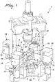
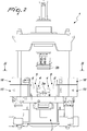
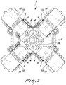
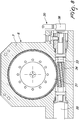
- the apparatus for molding materials according to the invention comprises a base frame 2 which supports a pair of half molds 3a and 3b, which can move with respect to each other and between which the material to be molded can be interposed.
- the apparatus according to the invention is furthermore provided with at least one plunger 4, which can be introduced between the half molds 3a and 3b and can be actuated translationally, with respect to the half molds 3a, 3b, by virtue of actuation means 5.
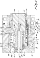
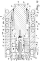
- the actuation means 5 comprise at least one actuation cylinder 6, which is provided with a lateral jacket 7, which forms axially an internal cavity 8, within which a piston 9 can move slidingly and is integral with a stem 10 connected to the plunger 4.
- the lateral jacket 7 has, at one of its ends, an opening 11, crossed by the stem 10 and, at its opposite end, a fixed head 12 for the closure of the internal cavity 8.
- a guiding ring 11a for the stem 10 can be mounted on the lateral jacket 7 at the opening 11.
- the piston 9 is, in particular, movable on command, along the internal cavity 8, between a retracted position, shown for example in Figure 5 , in which the piston 9 is moved closer to the fixed head 12, and an advanced position, shown for example in Figure 7 , in which the piston 9 is moved away from the fixed head 12.
- the piston 9 and the fixed head 12 there are, between the piston 9 and the fixed head 12, at least two separate actuation chambers of the piston 9, respectively a first actuation chamber 13, which is formed between a first portion 9a of the piston 9 and at least one portion of the fixed head 12, and a second actuation chamber 14, which is separated hermetically from the first actuation chamber 13 and is formed between a second portion 9b of the piston 9, which is different from the first portion 9a, and at least one portion of the fixed head 12.
- the first actuation chamber 13 and the second actuation chamber 14 are connected to means 15 for supplying a working fluid, which comprise, conveniently, a fluid-operated circuit which may be of the open circuit type or of the closed circuit type.
- means 16 for the control of the supply means 15 which are designed to activate the supply means 15 in order to supply in sequence with the pressurized working fluid the first actuation chamber 13, in order to produce a movement of the piston 9, for at least one first part of its stroke from the retracted position to the advanced position, with the generation of a first value of the force applied to the plunger 4, and the second actuation chamber 14, in order to produce a movement of the piston 9, for at least one second part of its stroke from the retracted position to the advanced position, with the generation of a second value, which is greater than the above mentioned first value, of the force applied to the plunger 4.
- said first part of the stroke of the piston 9 is extended preferably between the retracted position and an intermediate position of the stroke, interposed between the retracted position and the advanced position, while said second part of the stroke of the piston 9 is extended between the intermediate position and the advanced position.
- a third actuation chamber 17 is formed in the internal cavity 8, between a third portion 9c of the piston 9, directed toward the opening 11 of the lateral jacket 7, and at least one portion of the fixed head 12 or at least one portion that is integral therewith and with the lateral jacket 7.
- control means 16 are designed to activate the supply means 15 in order to supply with the pressurized working fluid the third actuation chamber 17, in order to produce a movement of the piston 9 from the advanced position toward the retracted position.
- the surface of the third portion 9c of the piston 9 on which the working fluid acts in the third actuation chamber 17 can have a smaller extension than the one of the first and second portions 9a and 9b of the piston 9 on which the working fluid acts respectively in the first and second actuation chambers 13 and 14, so that the piston 9 can perform a low force return step from the advanced position to the retracted position, i.e., with the generation of a value of the force applied by the piston 9 that is lower than the values of the force applied by the piston in the movement steps of the piston 9 from the retracted position to the advanced position, thus avoiding the risk of any breakage of the components mounted on the piston 9.
- the first portion 9a of the piston 9 is formed in a central region of said piston, with respect to its axis, while the second portion 9b of the piston 9 is formed in a peripheral region of the piston 9, again with respect to its own axis.
- a fixed piston 18 is fixed integrally to the fixed head 12, has an elongated extension and is extended axially, in the internal cavity 8, from the fixed head 12 toward the opening 11 of the lateral jacket 7.
- a longitudinal recess 19 is axially formed in the piston 9, accommodates the fixed piston 18 and in particular has, at one of its ends arranged substantially at a face 9d of the piston 9 that is directed toward the fixed head 12, an inlet 20 crossed by the fixed piston 18.
- the first actuation chamber 13 is formed between the end of the fixed piston 18 that is opposite to the one fixed to the fixed head 12 and a bottom wall 21 of the longitudinal recess 19 that is located at the end of the longitudinal recess that is opposite to the one in which the inlet 20 is formed and which, in practice, forms the first portion of the piston 9.
- the fixed piston 18 is crossed longitudinally by at least one first channel 22 which connects the supply means 15 to the first actuation chamber 13.
- the third actuation chamber 17 is provided by an annular interspace 23 formed between at least one portion of the outer lateral surface of the fixed piston 18 and at least one portion of the internal lateral surface of the longitudinal recess 19.
- the fixed piston 18 is crossed longitudinally by at least one second channel 24 which communicates with the annular interspace 23 and with the supply means 15.
- the fixed piston 18 conveniently has, at its end that is opposite with respect to the end that is fixed to the fixed head 12, a wider head 18a, which engages hermetically the internal lateral surface of the longitudinal recess 19, with the possibility of the piston 9 to slide with respect to the fixed piston 18.
- a guiding bush 20a is fixed to the piston 9 at the inlet 20 of the longitudinal recess 19 and engages hermetically the outer lateral surface of the fixed piston 18, with the possibility of the piston 9 to slide with respect to the fixed piston 18.
- annular interspace 23 that provides the third actuation chamber 17 is delimited axially between a region of the wider head 18a of the fixed piston that is directed oppositely with respect to the opening 11 and a region of the guiding bush 20a that is directed toward the opening 11 which, in practice, forms the above mentioned third portion 9c of the piston 9.
- the second portion 9b of the piston 9 comprises a region of the face 9d of the piston 9 that is located around the inlet 20 of the longitudinal recess 19.
- the second portion 9b of the piston is formed at a radial head expansion 25 of the piston 9, which has larger diametrical dimensions than the remaining part of the piston 9, which is arranged at the end of the piston 9 that is directed toward the fixed head 12 and engages hermetically the side wall of the internal cavity 8, on which a cooling jacket 26 can be advantageously arranged.
- At least one third channel 27, which connects the supply means 15 to the second actuation chamber 14, is formed in the fixed head 12.
- the piston 9 axially accommodates, substantially at the bottom wall 21 of the longitudinal recess 19, a transducer 28 of the stroke of the piston 9.
- abutment element 29 which can be engaged by the piston 9 and can be moved adjustably by virtue of means for movement 30 along the axis of the lateral jacket 7 in order to vary the extension of the stroke of the piston 9 between the retracted position and the advanced position.
- the abutment element 29 comprises, conveniently, a sleeve-like stroke limiter body 29a, which is movable along the axis of the lateral jacket 7 and is arranged coaxially to the lateral jacket 7 between the opening 11 and an abutment portion 9e of the piston 9, which is arranged, advantageously, in the case of the embodiment of Figures 5-7 , on the side of the radial head expansion 25 of the piston 9 that is directed toward the opening 11.
- the movement means 30 comprise, advantageously, a movement ring 31, which is mounted so that it can rotate with respect to the lateral jacket 7 and is arranged around the stroke limiter body 29a, inside the lateral jacket 7.
- the movement ring 31 is provided internally with a thread 32, which engages a corresponding complementary thread formed on the stroke limiter body 29a, and an external set of teeth 33 which engages a worm screw 34, which is extended substantially at right angles to the axis of the movement ring 31 and can be actuated rotationally by a motor 35 controlled by means of an encoder 36.
- the movement ring 31 is axially locked by means of an abutment ring 37.
- the rotation-preventing element 38 allows moreover to provide the rotational locking of the abutment element 29.
- the apparatus according to the invention may be provided with multiple plungers 4, each of which is functionally connected to a respective actuation cylinder 6.
- the material to be molded is interposed between the half molds 3a and 3b and then the approach of the two half molds 3a and 3b is actuated.
- One or more plungers 4 are then inserted into the half molds 3a and 3b by means of the activation of the respective actuation cylinders 6.
- each actuation cylinder 6 is managed by the control means 16 of the supply means 15 according to the following steps.
- the control means 16 actuate the activation of the supply means 15 in order to send, via the first channel 22, pressurized working fluid into the first actuation chamber 13, so as to cause the movement of the piston 9 in the direction of the advanced position for the first part of its stroke, i.e., until it reaches the intermediate position, which can be set by the user by means of a control panel.
- the working fluid present in the third actuation chamber 17 returns, through the second channel 24, to the supply means 15 and working fluid at low pressure is introduced in the second actuation chamber 14 via the third channel 27.
- a second step or step of high force advancement of the piston 9 starts in which, while the piston 9 travels along a second part of its stroke toward the advanced position, the control means 16 actuate the supply means 15 to send, via the third channel 27, the pressurized working fluid into the second actuation chamber 14 so as to obtain the generation of a greater working force by the piston 9.
- the stroke of the piston 9 ends when the piston 9 comes into contact with the abutment element 29, previously positioned by virtue of its movement means 30, thus allowing to adjust in a precise manner the extension of the stroke of the piston 9.
- control means 16 actuate the supply means 15 to send the pressurized working fluid into the third actuation chamber 17, so as to obtain the movement of the piston 9 from the advanced position to the retracted position, with return of the working fluid present in the first and second actuation chambers 13 and 14 into the supply means 15 via the first and third channels 22 and 27.
- the invention allows the elimination of accumulators of large size operating at high pressures, by virtue of the possibility to use a closed circuit without an oil tank to provide the means for supplying the actuation cylinder of the plungers.
- Another achieved advantage of the invention is constituted by the possibility to vary in a simple and effective manner the advancement and final force without having to adjust valves and/or preload accumulators.
- Another advantage of the invention is to allow an adjustment of the exit level of the piston that actuates the plunger, by virtue of means incorporated in the lateral jacket of the actuation cylinder.
- Figures 9-11 show a possible constructive variation of the actuation cylinder 6, in which components and elements similar to those of the embodiment of Figures 5-7 have been designated by the same reference numeral for the sake of simplicity.
- the piston 9 has an axial extension 40 that extends from the piston 9 in the direction of the fixed head 12 and in which the longitudinal recess 19 that accommodates the fixed piston 18 is formed, said piston in this case being crossed longitudinally by a receptacle 41 for a rod, not shown for the sake of simplicity, that is designed to interact with the transducer 28 of the stroke of the piston 9 arranged at the bottom wall 21 of the longitudinal recess 19.
- the first actuation chamber 13 is formed between the fixed head 12 and the free end of the axial extension 40 of the piston 9 and, more particularly, between the fixed head 12 and a collar 42 which is fixed around a portion of the axial extension 40 proximate to its free end and forms, with its portion directed toward the fixed head 12, the first portion 9a of the piston 9.
- the collar 42 engages slidingly and hermetically the inner side wall of a sleeve-like body 43, which is accommodated, integrally with the fixed head 12 and the lateral jacket 7, in an axial part of the internal cavity 8 of the lateral jacket 7 of the actuation cylinder 6.
- the sleeve-like body 43 in turn axially accommodates with play in its internal axial cavity 43a the axial extension 40 and, inside it there is, in practice, the first actuation chamber 13, which in this case communicates with the supply means 15 via a duct 44 that passes through the fixed head 12.
- the second actuation chamber 14 is formed externally to the axial extension 40 of the piston 9 and more particularly is defined conveniently in a portion of space substantially comprised radially between the external lateral surface of the axial extension 40 of the piston 9 and the internal surface of the lateral jacket 7 and axially between a peripheral portion of the piston 9 that extends around the axial extension 40 and forms the second portion 9b of the piston 9 and the end of the sleeve-like body 43 directed toward the opening 11 of the lateral jacket 7.
- the second actuation chamber 14 communicates with the supply means 15 via the third channel 27 formed in the fixed head 12 and a connecting duct 45, which is extended longitudinally in the sleeve-like body 43 and is arranged laterally with respect to the internal axial cavity 43a of said sleeve-like body.
- a tubular extension 43b of the sleeve-like body 43 extends axially from the end of the sleeve-like body 43 directed toward the opening 11 of the lateral jacket 7, at the external edge of the sleeve-like body 43, and is engaged slidingly and hermetically, on its internal lateral surface, by the piston 9 and is in contact, with its external lateral surface, with the internal surface of the lateral jacket 7.
- the cooling jacket 26 is, in this case, formed between the lateral jacket 7 and the external lateral surface of the sleeve-like body 43 and of its tubular extension 43b.
- the third actuation chamber 17 can be conveniently defined in a region of the internal axial cavity 43a of the sleeve-like body 43 that is separated hermetically with respect to the first actuation chamber 13 by the collar 42.
- the third actuation chamber 17 is formed in a portion of space 47, located inside the internal axial cavity 43a of the sleeve-like body 43, that is comprised radially between the internal lateral wall of the internal axial cavity 43a of the sleeve-like body 43 and the external lateral surface of the axial extension 40 of the piston 9 and, axially, between a portion of the collar 42 directed toward the opening 11, which defines in practice the third portion 9c of the piston 9, and an annular wall 46, which is extended radially from the internal lateral wall of the internal axial cavity 43a of the sleeve-like body 43 and engages slidingly hermetically the external lateral surface of the axial extension 40 of the piston 9.
- Said portion of space 47 communicates with the supply means 15, for example, by means of a radial duct 48 which crosses the lateral jacket 7 and the sleeve-like body 43.
- the third actuation chamber 17 may also optionally be formed in a portion of space of the internal cavity 8 of the lateral jacket 7 that is comprised axially between the opening 11 and the piston 9.
- the third actuation chamber 17 may be formed between the abutment element 29 and the abutment portion 9e of the piston 9, which therefore also defines the third portion 9c of said piston, and can be arranged in communication with the supply means 15 by virtue of a radial channel 49, which is formed in the lateral jacket 7 and communicates with an aperture 50 formed in the axial extension 43b of the sleeve-like body 43.
- the first actuation chamber 13 might also be in communication with the inside of the longitudinal recess 19 that accommodates the fixed piston 18 via a passage 51 left open between a portion of the internal lateral surface of the longitudinal recess 19 and the external lateral surface of the fixed piston 18 and, more particularly, between the rotation-preventing element 38, in this case inserted in the longitudinal cavity 19 and fixed to the axial extension 40 of the piston 9, and the external lateral surface of the fixed piston 18.
- the materials used may be any according to the requirements and the state of the art.
Landscapes
- Engineering & Computer Science (AREA)
- Mechanical Engineering (AREA)
- Physics & Mathematics (AREA)
- Fluid Mechanics (AREA)
- General Engineering & Computer Science (AREA)
- Processing And Handling Of Plastics And Other Materials For Molding In General (AREA)
- Glass Compositions (AREA)
- Moulds For Moulding Plastics Or The Like (AREA)
Applications Claiming Priority (1)
| Application Number | Priority Date | Filing Date | Title |
|---|---|---|---|
| IT102019000012969A IT201900012969A1 (it) | 2019-07-26 | 2019-07-26 | Apparecchiatura per lo stampaggio di materiali. |
Publications (1)
| Publication Number | Publication Date |
|---|---|
| EP3769949A1 true EP3769949A1 (de) | 2021-01-27 |
Family
ID=68733504
Family Applications (1)
| Application Number | Title | Priority Date | Filing Date |
|---|---|---|---|
| EP20184762.1A Withdrawn EP3769949A1 (de) | 2019-07-26 | 2020-07-08 | Vorrichtung zum formen von materialien |
Country Status (2)
| Country | Link |
|---|---|
| EP (1) | EP3769949A1 (de) |
| IT (1) | IT201900012969A1 (de) |
Cited By (1)
| Publication number | Priority date | Publication date | Assignee | Title |
|---|---|---|---|---|
| EP4667131A1 (de) | 2024-06-17 | 2025-12-24 | Praber S.r.l. | Formpresse |
Citations (10)
| Publication number | Priority date | Publication date | Assignee | Title |
|---|---|---|---|---|
| US1552768A (en) * | 1922-10-31 | 1925-09-08 | Eric M Smith | Hydraulic press apparatus |
| GB938616A (en) * | 1959-02-14 | 1963-10-02 | Ges Fertigungstechnik & Maschb | Improvements in or relating to swaging machines |
| US3563136A (en) * | 1969-02-14 | 1971-02-16 | Manco Mfg Co | Variable force hydraulic press |
| GB1302095A (de) * | 1969-04-05 | 1973-01-04 | ||
| US3822456A (en) * | 1970-03-30 | 1974-07-09 | Anaconda Co | Strand connecting method |
| FR2314824A1 (fr) * | 1975-06-19 | 1977-01-14 | Herve Rene | Presse a poinconner multi-usages |
| US4823658A (en) * | 1985-10-18 | 1989-04-25 | Spicer Andrew I | Punch presses |
| WO1996026023A1 (en) * | 1995-02-24 | 1996-08-29 | Amada Company, Ltd. | Hydraulic actuator for punches and suchlike movable members for working sheet metal, and hydraulic system incorporating this actuator |
| EP2210686A1 (de) | 2009-01-21 | 2010-07-28 | Mecolpress S.p.A. | Presse zum Heisspressen eines Rohlings mit geschlossenem Gesenk |
| US20190217373A1 (en) * | 2016-04-11 | 2019-07-18 | SMS group GmbH | Hydraulic cylinder |
Family Cites Families (1)
| Publication number | Priority date | Publication date | Assignee | Title |
|---|---|---|---|---|
| DE2645849A1 (de) * | 1976-10-11 | 1978-04-13 | Osterwalder Ag | Hydraulisch angetriebene presse |
-
2019
- 2019-07-26 IT IT102019000012969A patent/IT201900012969A1/it unknown
-
2020
- 2020-07-08 EP EP20184762.1A patent/EP3769949A1/de not_active Withdrawn
Patent Citations (10)
| Publication number | Priority date | Publication date | Assignee | Title |
|---|---|---|---|---|
| US1552768A (en) * | 1922-10-31 | 1925-09-08 | Eric M Smith | Hydraulic press apparatus |
| GB938616A (en) * | 1959-02-14 | 1963-10-02 | Ges Fertigungstechnik & Maschb | Improvements in or relating to swaging machines |
| US3563136A (en) * | 1969-02-14 | 1971-02-16 | Manco Mfg Co | Variable force hydraulic press |
| GB1302095A (de) * | 1969-04-05 | 1973-01-04 | ||
| US3822456A (en) * | 1970-03-30 | 1974-07-09 | Anaconda Co | Strand connecting method |
| FR2314824A1 (fr) * | 1975-06-19 | 1977-01-14 | Herve Rene | Presse a poinconner multi-usages |
| US4823658A (en) * | 1985-10-18 | 1989-04-25 | Spicer Andrew I | Punch presses |
| WO1996026023A1 (en) * | 1995-02-24 | 1996-08-29 | Amada Company, Ltd. | Hydraulic actuator for punches and suchlike movable members for working sheet metal, and hydraulic system incorporating this actuator |
| EP2210686A1 (de) | 2009-01-21 | 2010-07-28 | Mecolpress S.p.A. | Presse zum Heisspressen eines Rohlings mit geschlossenem Gesenk |
| US20190217373A1 (en) * | 2016-04-11 | 2019-07-18 | SMS group GmbH | Hydraulic cylinder |
Cited By (1)
| Publication number | Priority date | Publication date | Assignee | Title |
|---|---|---|---|---|
| EP4667131A1 (de) | 2024-06-17 | 2025-12-24 | Praber S.r.l. | Formpresse |
Also Published As
| Publication number | Publication date |
|---|---|
| IT201900012969A1 (it) | 2021-01-26 |
Similar Documents
| Publication | Publication Date | Title |
|---|---|---|
| US3156014A (en) | Injection molding machine | |
| JPS603977B2 (ja) | プラスチツク射出成形機用型締め装置 | |
| ES482528A1 (es) | Maquina de fundicion a presion. | |
| AU718303B2 (en) | Single acting pneumatic piston-cylinder unit | |
| EP3769949A1 (de) | Vorrichtung zum formen von materialien | |
| US4029457A (en) | Molding machine | |
| US9056418B2 (en) | Injection apparatus | |
| KR100259876B1 (ko) | 기계프레스의 슬라이드 하사점 위치 조정장치 | |
| KR100219358B1 (ko) | 실린더식가공장치 | |
| US3554087A (en) | Hydraulic closing device particularly for injection molding machines | |
| DK1924773T3 (en) | Control device and control method for a piston-cylinder device | |
| KR20000053334A (ko) | 차단장치를 가진 유공압 서보모터 | |
| US2893082A (en) | Device for increasing the capacity of die casting machines | |
| JP4868972B2 (ja) | クロージング加工装置及びクロージング加工方法 | |
| JP4792492B2 (ja) | 金型装置 | |
| JP2025149401A (ja) | ダイカストマシンの速度制御用バルブ及びダイカストマシン | |
| US20040216600A1 (en) | Drive mechanism, particularly for a moveable part of a closing unit or the injection unit of a plastic injection moulding machine | |
| JPS63212524A (ja) | 射出成形機における型締装置 | |
| KR100534735B1 (ko) | 유압 실린더 | |
| SU943428A1 (ru) | Гидроусилитель регулируемой гидромашины | |
| SU1291281A1 (ru) | Устройство дл запрессовки металла машины лить под давлением | |
| IT201900012960A1 (it) | Apparecchiatura per lo stampaggio di materiali. | |
| RU2240233C1 (ru) | Пресс двойного действия | |
| KR100473562B1 (ko) | 전기유변유체를 이용한 형체결장치 | |
| GB1282101A (en) | Improvements in fluid pressure operated mechanisms |
Legal Events
| Date | Code | Title | Description |
|---|---|---|---|
| PUAI | Public reference made under article 153(3) epc to a published international application that has entered the european phase |
Free format text: ORIGINAL CODE: 0009012 |
|
| STAA | Information on the status of an ep patent application or granted ep patent |
Free format text: STATUS: THE APPLICATION HAS BEEN PUBLISHED |
|
| AK | Designated contracting states |
Kind code of ref document: A1 Designated state(s): AL AT BE BG CH CY CZ DE DK EE ES FI FR GB GR HR HU IE IS IT LI LT LU LV MC MK MT NL NO PL PT RO RS SE SI SK SM TR |
|
| AX | Request for extension of the european patent |
Extension state: BA ME |
|
| STAA | Information on the status of an ep patent application or granted ep patent |
Free format text: STATUS: THE APPLICATION IS DEEMED TO BE WITHDRAWN |
|
| 18D | Application deemed to be withdrawn |
Effective date: 20210728 |