EP3769966A1 - Guidage automatique de menu d'utilisation assisté au niveau de couleurs - Google Patents
Guidage automatique de menu d'utilisation assisté au niveau de couleurs Download PDFInfo
- Publication number
- EP3769966A1 EP3769966A1 EP20183354.8A EP20183354A EP3769966A1 EP 3769966 A1 EP3769966 A1 EP 3769966A1 EP 20183354 A EP20183354 A EP 20183354A EP 3769966 A1 EP3769966 A1 EP 3769966A1
- Authority
- EP
- European Patent Office
- Prior art keywords
- printing machine
- printing
- print job
- displays
- computer
- Prior art date
- Legal status (The legal status is an assumption and is not a legal conclusion. Google has not performed a legal analysis and makes no representation as to the accuracy of the status listed.)
- Granted
Links
Images

Classifications
-
- B—PERFORMING OPERATIONS; TRANSPORTING
- B41—PRINTING; LINING MACHINES; TYPEWRITERS; STAMPS
- B41F—PRINTING MACHINES OR PRESSES
- B41F33/00—Indicating, counting, warning, control or safety devices
- B41F33/0009—Central control units
-
- B—PERFORMING OPERATIONS; TRANSPORTING
- B41—PRINTING; LINING MACHINES; TYPEWRITERS; STAMPS
- B41F—PRINTING MACHINES OR PRESSES
- B41F33/00—Indicating, counting, warning, control or safety devices
- B41F33/02—Arrangements of indicating devices, e.g. counters
Definitions
- the present invention relates to a printing machine with printing units, a computer and a display device, the printing units having optical signaling devices which are connected to the computer and the computer being connected to the display device.
- a printing machine which is equipped with lighting devices on printing units.
- the lighting devices on the printing units are intended to visually clarify the state of the printing press to the operator, the operator being able to recognize the lighting devices on the printing units even if he is a little further away from the printing press.
- the lighting devices are mounted on the side walls of the printing units of the printing machine and the current operating status of the printing machine is recorded by several sensors and forwarded to a control computer.
- This control computer in turn controls the lighting devices on the printing units, which z. B. show a remaining amount of ink on the respective printing unit.
- the display of the amount of ink is based on information that the sensors deliver to the printing press control computer.
- the disadvantage of this printing press is that the display of the information on the printing units is not related to other operating elements of the printing press, in particular a display device such as a screen.
- a method for determining the optimal procedure for a job change on a printing press with at least one control computer is also known.
- the control computer compares the data of a first machine job with the data of a subsequent machine job and uses the comparison to calculate a sequence of the work that will become due when changing jobs.
- the operating personnel is guided through these workflows visually to carry out the job change on the basis of the calculated sequence of the workflows, the workflows being visualized on display devices which are attached to the printing machine.
- the object of the present invention is to reduce downtimes in printing presses and to optimize operator actions on the printing press by optimizing the operator guidance for the printing press operator.
- the printing machine can be an offset printing machine, an inkjet printing machine or another printing machine with any printing technology, which is equipped at least with a printing device such as a printing unit.
- the printing press must have a computer which is connected to at least one display device such as a screen and optical signal devices on the printing units of the printing press. In this way, the computer can coordinate and control the display process on the optical signal devices on the display device.
- the printing machine is set up so that the computer displays the operating states of the printing machine on the display device in a color matching the displays of the operating states on the optical signaling devices of the printing units.
- the printing press operator an operating state of the printing press both on a display device such. B. is displayed on the operating screen of the printing machine in the same or at least similar color as the operating state on the optical signal device on the respective printing unit.
- the display of the operating states on the screen and on the respective printing unit is visually coordinated by the color-matched display, so that confusion for the operator is as good as impossible.
- the color display on the optical signaling devices and on the display device takes place in exactly the same color tone, but certain deviations in the color tone, which do not lead to confusion, are quite permissible.
- an optical signaling device on a printing unit simultaneously or alternately displays a plurality of operating states in different colors.
- several actions can be pending or carried out on a printing unit.
- the optical signaling device In order to be able to display these multiple actions on a printing unit, it is possible for the optical signaling device to display different colors at the same time or alternately. With simultaneous display, this means that the optical signaling device is divided into two or more areas and a different color is displayed in each area, which is assigned to a specific operating state. In this way, the status "Setup due to print job change" and "Manual intervention required" can be displayed on a printing unit with two different colors. Furthermore, it is also possible to alternately display different colors on the optical signaling device of the printing unit by changing the color at time intervals, in particular pulsing, i.e. H. a quick color change is possible.
- the optical signaling device is a multicolor LED light strip.
- Modern multicolor LEDs have the great advantage that they can be shaped in almost any way, use little energy and can produce a wide range of colors. In this way it is possible to attach an optical signal device of almost any shape to the printing unit and to let it shine in almost any number of colors. Because each color is assigned an operating state, almost any number of operating states can be displayed in different colors. It is only important that the operator can distinguish between the colors of the different operating states visually so that no mix-ups occur.
- the LEDs can also be arranged in the multicolor signal device as an array with a certain width and a certain length with several LEDs next to one another and one below the other, so that arrows or other symbols can be displayed in color.
- a user interface with at least one mask is provided on the display device is displayed, a time line being present in an area of the mask, which chronologically displays the print jobs assigned to the printing press in a print job queue.
- the display device can be designed as a pure display device, in particular as a large wall screen, on the control panel of the printing machine, but it can also be a separate touchscreen that receives the user interface with inputs from the operator of the printing machine.
- the user interface can also run on a mobile device such as a smartphone or tablet to enable mobile applications. The user interface can thus enable direct inputs or can only be used as a display that is controlled via other input devices such as a mouse or keyboard.
- a time line is then permanently present which chronologically displays the print jobs assigned to the printing press in a print job queue.
- the print job queue is preferably displayed in the same color that is used on the printing units to signal the operating state "continuous printing".
- the user interface contains a mask with an area which displays properties of a current print job and properties of an upcoming print job
- the computer provides suggestions on the user interface for coping with the print job change between the current and the coming one Print job shows which manual interventions by an operator include.
- a mask is displayed in good time on the user interface, which contains an area in which the properties such as edition, printing inks, substrate, name of the client, etc., of both an ongoing and an upcoming print job are displayed, so that the operator can see immediately what happens when the print job is switched between the current print job and the upcoming print job changes.
- suggestions for coping with the print job change between the current and the upcoming print job are displayed on the mask, which include manual interventions by an operator. So that the operator of the printing press can correctly carry out the necessary manual interventions, the computer of the printing press also displays appropriate suggestions for coping with the print job change on a screen so that he is optimally prepared for the upcoming manual interventions. In addition, these manual interventions can then be signaled by corresponding identical coloring on the user interface of the display device and the optical signal device on the respective printing unit.
- the computer displays a further mask on the display device at the beginning of the print job change, which shows the ongoing setup processes of a printing machine, and that the optical signal devices on the printing units of the printing machine display the corresponding setup processes in a matching color.
- the mask changes at the beginning of the print job change, in that another mask is displayed, which then shows the set-up processes in progress on the printing machine, with the corresponding set-up processes being color-coordinated on the user interface and on the optical signal devices of the printing units.
- manual setup processes are displayed in a different color than automatic setup processes on the display device and on the optical signal devices of the printing units.
- a color distinction is made between manual setup processes and automatic setup processes.
- the computer displays a mask on the user interface which, during the set-up phase up to the start-up of the production of a print job after a print job change, displays in particular areas for displaying color dosage and color measurement results.
- another mask is displayed on the user interface during the set-up phase until the production of a print job starts up, which shows important information during this set-up phase.
- This mask contains in particular areas for displaying the color dosage and color measurement results. Since the printing press is not in a stable state during the set-up phase until the production of a print job is started up, the production of the printed products must e.g. B.
- color measurement results are then displayed in the mask during the setup phase, so that the printer can see whether the color measurement results are in the desired range. It is also advantageous if the operator is given a display of the ink dosage, especially in the case of zonal inking units in offset printing machines, so that the operator always has an eye on the openings of the individual ink zones in the printing units on the user interface in the mask. Thus, color measurement results and openings of the ink metering elements in the printing press can be placed directly next to one another in the same mask, which significantly increases the clarity for the operator.
- the computer displays a mask on the user interface of the display device which contains measured color values and displays the openings of ink metering elements in the printing units of the printing machine.
- another mask is preferably displayed on the user interface, which is only available during ongoing production is used and here, too, displays the corresponding measured color values and openings of ink metering elements in the printing units of the printing machine. The operator knows immediately that he is in the ongoing production of the print job and that the print quality of the current print job is now being monitored.
- the computer displays a mask on the user interface of the display device during the production of a print job, which shows deviations in the print quality between printed substrates and a print original on the basis of measured values determined by a measuring device and changes to the setting the press suggests as a remedy.
- a target / actual value comparison between digital data of the print original and the measured values determined by a measuring device is carried out and corresponding deviations are displayed in the mask during the production of the print job.
- suggestions are displayed in the mask as to how the deviations from the print original can be minimized by changing the settings of the printing machine.
- the printer has both measured values and suggestions for changing the setting in the event of impermissible deviations in the same mask at a glance; suggestions for changing the settings of the printing machine can also be in the same or in a separate Mask on the user interface.
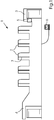
- a sheet-fed offset printing machine 1 is shown as an example, which has six printing units 2, a feeder 3, a boom 4 and an operating point 5.
- the control point 5 which has a display device in the form of a screen, the entire printing machine or parts of the printing machine can be controlled. In addition, it is possible to provide a large screen such as a wallscreen, which is in Figure 1 is not shown.
- the control point 5 is connected to a control computer 6 which controls the printing press 1.
- the control computer 6 controls both the printing units 2 and the feeder 3 and the boom 4.
- An LED light strip 7, which can light up in different colors, is attached to each printing unit 2.
- the LED light strips 7 are also coupled to the control computer 6, so that the control computer 6 can control the LED light strips 7 according to color.
- the light strips 7 show different colors depending on the operating state of the associated printing unit 2. Continuous printing is displayed in blue, while an automatic set-up process is displayed in green. If manual intervention by the operator is required on a printing unit 2, the associated LED light strip 7 lights up in the color yellow. On the screen of the control point 5, the corresponding machine statuses are displayed in the same color as on the LED light strip 7 of the associated printing unit 2. In this way, the operator can visually assign the displays on the printing unit 2 and the displays on the control point 5 in terms of color. If several operating states are to be displayed on a printing unit 2, the LED light strip 7 can be controlled in such a way that it alternately displays different colors in succession or at the same time in at least two areas, which are assigned to different operating states of the printing press 1. In this way, several operating states can be displayed at the same time on a printing unit 2 by means of an LED light strip 7.
- a user interface 8 is shown, which is displayed on the control point 5.
- the printing press 1 is controlled with the user interface 8.
- To the relevant process instructions for the current machine status are displayed to the operator on the user interface 8 at any time.
- the system guides the operator and automatically suggests the next necessary steps.
- the appropriate masks for the respective process on the printing machine 1 are displayed on the user interface 8, so that the operator knows at all times which process is currently pending on the printing machine 1.
- the current operating status of the printing press 1 is shown for all people involved in the printing process, such as B. printers, helpers, print shop managers made widely visible.
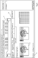
- a mask is shown on the user interface 8, which is automatically displayed at the start of a print job change. It can be seen that the print job queue 13 is always displayed in the lower area of the mask, so that the operator always has an overview of the print jobs pending on the printing press 1. There is also an area 11 which displays the properties and data of a print job before the print job change, while an area 12 displays the properties and data of a print job after the print job change. The operator thus knows which settings must be changed on the printing press 1 in order to be able to carry out the print job change. In addition, there is an area 10 in the mask which shows the processes taking place on the printing units 2 during the print job change.
- the processes running on the printing units 2 are displayed in the mask in the same color as they are on the respective one Printing unit 2 can be signaled by the LED light strips 7. Above this area, the printing machine 1 is shown in the area 9, so that there is an additional assignment between color-coded processes at the printing units on the display device 5 when changing print jobs and the respective printing unit 2 in the printing machine 1. In this case, ongoing setup processes on the printing units 2 are displayed in green, while the respective printing unit and the respective process are colored yellow in the case of manual interventions.
- FIG 3 Another mask is shown on the user interface 8, which is displayed during the setup phase until the next print job starts up.
- This mask is also referred to as a so-called fine-tuning mask and consists of two states and starts with the first printing unit 2 when this is switched to printing.
- the first state comprises the start-up of the printing machine 1 up to the first measurement of a printed product produced by a color measuring device, a preview image 14 of the print job with ink zone profile of the printing machine 1 is displayed, the printing circuit and machine setting and the respective color register.
- the second state is displayed from the first measurement up to the start of a good sheet.
- the ink zone display is then replaced by the measurement results, the remaining displays remain the same. If the printing press 1 is operated without a color measuring device, the mask remains in the first state.
- the mask changes to the production state and, if a color measuring device is available, a print quality control is carried out, with measurement results being displayed in the mask compared to the original.
- the concept with the various masks has the advantage that the operator at the control point 5 and its user interface 8 is only ever shown the mask that matches the process in the printing machine 1 and is guided dynamically through the processes on the printing machine 1.
- the operator is not flooded with information, but is only confronted with the information that matches the processes currently running on the printing press 1. In this way, operation is made more intuitive and operating errors by the operator are avoided. This reduces downtimes of the printing machine 1 and increases the safety of production.
Landscapes
- Inking, Control Or Cleaning Of Printing Machines (AREA)
Applications Claiming Priority (1)
| Application Number | Priority Date | Filing Date | Title |
|---|---|---|---|
| DE102019211129.7A DE102019211129A1 (de) | 2019-07-26 | 2019-07-26 | Farblich unterstützte automatische Bedienmenüführung |
Publications (2)
| Publication Number | Publication Date |
|---|---|
| EP3769966A1 true EP3769966A1 (fr) | 2021-01-27 |
| EP3769966B1 EP3769966B1 (fr) | 2022-10-19 |
Family
ID=71409302
Family Applications (1)
| Application Number | Title | Priority Date | Filing Date |
|---|---|---|---|
| EP20183354.8A Active EP3769966B1 (fr) | 2019-07-26 | 2020-07-01 | Guidage automatique de menu d'utilisation assisté au niveau de couleurs |
Country Status (4)
| Country | Link |
|---|---|
| EP (1) | EP3769966B1 (fr) |
| JP (1) | JP3228558U (fr) |
| CN (1) | CN112297621B (fr) |
| DE (1) | DE102019211129A1 (fr) |
Families Citing this family (3)
| Publication number | Priority date | Publication date | Assignee | Title |
|---|---|---|---|---|
| DE102021109029A1 (de) | 2021-04-12 | 2022-10-13 | Koenig & Bauer Ag | Verfahren zum optimierten Auftragswechsel an einer bogenverarbeitenden Maschine |
| DE102024102872A1 (de) | 2024-02-01 | 2025-02-27 | Koenig & Bauer Ag | Verfahren zur Absicherung der Qualität eines Druckproduktes |
| DE102024114244B3 (de) * | 2024-05-22 | 2025-06-18 | Heidelberger Druckmaschinen Aktiengesellschaft | Software gestütztes Verfahren zur Bedienerführung bei Druckmaschinen |
Citations (4)
| Publication number | Priority date | Publication date | Assignee | Title |
|---|---|---|---|---|
| DE10339571A1 (de) * | 2002-09-13 | 2004-03-25 | Heidelberger Druckmaschinen Ag | Verfahren und Vorrichtung zur Optimierung eines Auftragswechsels |
| JP2009202378A (ja) | 2008-02-27 | 2009-09-10 | Ryobi Ltd | 照明装置を備えた印刷機 |
| EP2112975A2 (fr) * | 2007-02-20 | 2009-11-04 | Goss International Americas, Inc. | Etat d'un produit d'impression en temps réel |
| US10189671B2 (en) * | 2016-05-30 | 2019-01-29 | Muller Martini Holding Ag | Device and method for the subsequent processing of printed products |
Family Cites Families (8)
| Publication number | Priority date | Publication date | Assignee | Title |
|---|---|---|---|---|
| DE3220378C2 (de) * | 1982-05-29 | 1994-03-03 | Heidelberger Druckmasch Ag | Steuervorrichtung für eine Druckmaschine |
| DE4013286C2 (de) * | 1990-04-26 | 2001-04-12 | Roland Man Druckmasch | Steuerung für mehrere Druckmaschinen in einem Drucksaal |
| DE19636703C2 (de) * | 1996-09-10 | 1998-12-03 | Roland Man Druckmasch | Vorrichtung zur automatischen Steuerung eines Druckplattenwechselvorganges |
| US6874420B2 (en) * | 1999-10-22 | 2005-04-05 | Cc1, Inc. | System and method for register mark recognition |
| DE102004015333B4 (de) * | 2004-03-30 | 2015-09-03 | Koenig & Bauer Aktiengesellschaft | Einrichtung zur Überwachung verarbeitungstechnischer Vorgänge innerhalb von Druckmaschinen in Aggregatbauweise |
| DE102007025796B4 (de) * | 2007-06-02 | 2010-07-15 | Koenig & Bauer Aktiengesellschaft | Mobiler Leitstand einer Rotationsdruckmaschine |
| JP2010173249A (ja) * | 2009-01-30 | 2010-08-12 | Mitsubishi Heavy Ind Ltd | 印刷作業の特定装置及び方法、並びにコンピュータプログラム |
| DE102011100847B4 (de) * | 2011-05-06 | 2013-04-18 | Atlantic Zeiser Gmbh | Druckwerk |
-
2019
- 2019-07-26 DE DE102019211129.7A patent/DE102019211129A1/de not_active Withdrawn
-
2020
- 2020-06-19 CN CN202010565066.0A patent/CN112297621B/zh active Active
- 2020-07-01 EP EP20183354.8A patent/EP3769966B1/fr active Active
- 2020-07-22 JP JP2020003054U patent/JP3228558U/ja active Active
Patent Citations (5)
| Publication number | Priority date | Publication date | Assignee | Title |
|---|---|---|---|---|
| DE10339571A1 (de) * | 2002-09-13 | 2004-03-25 | Heidelberger Druckmaschinen Ag | Verfahren und Vorrichtung zur Optimierung eines Auftragswechsels |
| DE10339571B4 (de) | 2002-09-13 | 2016-01-21 | Heidelberger Druckmaschinen Ag | Verfahren zur Optimierung eines Auftragswechsels |
| EP2112975A2 (fr) * | 2007-02-20 | 2009-11-04 | Goss International Americas, Inc. | Etat d'un produit d'impression en temps réel |
| JP2009202378A (ja) | 2008-02-27 | 2009-09-10 | Ryobi Ltd | 照明装置を備えた印刷機 |
| US10189671B2 (en) * | 2016-05-30 | 2019-01-29 | Muller Martini Holding Ag | Device and method for the subsequent processing of printed products |
Also Published As
| Publication number | Publication date |
|---|---|
| EP3769966B1 (fr) | 2022-10-19 |
| CN112297621A (zh) | 2021-02-02 |
| CN112297621B (zh) | 2025-02-18 |
| JP3228558U (ja) | 2020-10-29 |
| DE102019211129A1 (de) | 2021-01-28 |
Similar Documents
| Publication | Publication Date | Title |
|---|---|---|
| EP0095649B1 (fr) | Dispositif pour commander l'alimentation en encre d'une machine à imprimer | |
| DE3718594C3 (de) | Steuerungsvorrichtung einer Druckmaschine | |
| EP1889721B2 (fr) | Tableau de commande d' une imprimante | |
| EP3769966B1 (fr) | Guidage automatique de menu d'utilisation assisté au niveau de couleurs | |
| EP0095664B1 (fr) | Dispositif de commande pour machines d'impression | |
| DE2727426A1 (de) | Vorrichtung zum steuern der farbfuehrung an rotationsdruckmaschinen | |
| DE102017207306A1 (de) | Verfahren zur Überwachung eines Färbungsstandards in einer Druckmaschine | |
| EP3757264B1 (fr) | Procédé de fonctionnement d'un métier à filer à filetage croisé partiellement ou entièrement automatique | |
| EP0356705A2 (fr) | Lecture de données pour un dispositif de réglage de l'encre | |
| EP2059394B2 (fr) | Dispositif de dosage de couleurs d'un groupe imprimant, et procédé de commande du dispositif de dosage de couleurs | |
| DE2830085C3 (de) | Verfahren und Vorrichtung zum Anzeigen von Stellgrößen | |
| DE102018202749B4 (de) | Verfahren zum Betrieb einer Maschine der grafischen Industrie | |
| DE102012013636B4 (de) | Steuerung von Farbwerken bei Druckgeschwindigkeitsänderungen | |
| DE102012020911B4 (de) | Färbungswächter für Druckmaschinen | |
| EP0990519B1 (fr) | Module de commande pour le dispositif de commande d'une machine à imprimer | |
| DE102014219102A1 (de) | Druckmaschine mit Bahnbeobachtung, welche durch die Registerregelung getriggert wird | |
| DE3334019A1 (de) | Verfahren und vorrichtung zur einstellung der den farbzonen eines farbwerks zugeordneten dosierorgane | |
| EP1864809B1 (fr) | Dispositif de contrôle d'une machine à imprimer | |
| DE102018202752A1 (de) | Verfahren zur Visualisierung manueller Bedienhandlungen | |
| DE19845915A1 (de) | Verfahren und Vorrichtung zur Farbzufuhrsteuerung | |
| EP4360881A1 (fr) | Dispositif d'impression et procédé d'impression pour une numérotation multicolore | |
| DE9309332U1 (de) | Bedieneinheit zur Steuerung von Feuchtwerken bei Offsetdruckmaschinen | |
| DE4102536A1 (de) | Verfahren zur erstellung von probedrucken einzelner farben oder farbkombinationen in einer druckmaschine | |
| DE102024102872A1 (de) | Verfahren zur Absicherung der Qualität eines Druckproduktes | |
| DE2727227A1 (de) | Einrichtung zur qualitaetssicherung von druckerzeugnissen |
Legal Events
| Date | Code | Title | Description |
|---|---|---|---|
| PUAI | Public reference made under article 153(3) epc to a published international application that has entered the european phase |
Free format text: ORIGINAL CODE: 0009012 |
|
| STAA | Information on the status of an ep patent application or granted ep patent |
Free format text: STATUS: THE APPLICATION HAS BEEN PUBLISHED |
|
| AK | Designated contracting states |
Kind code of ref document: A1 Designated state(s): AL AT BE BG CH CY CZ DE DK EE ES FI FR GB GR HR HU IE IS IT LI LT LU LV MC MK MT NL NO PL PT RO RS SE SI SK SM TR |
|
| AX | Request for extension of the european patent |
Extension state: BA ME |
|
| STAA | Information on the status of an ep patent application or granted ep patent |
Free format text: STATUS: REQUEST FOR EXAMINATION WAS MADE |
|
| 17P | Request for examination filed |
Effective date: 20210727 |
|
| RBV | Designated contracting states (corrected) |
Designated state(s): AL AT BE BG CH CY CZ DE DK EE ES FI FR GB GR HR HU IE IS IT LI LT LU LV MC MK MT NL NO PL PT RO RS SE SI SK SM TR |
|
| GRAP | Despatch of communication of intention to grant a patent |
Free format text: ORIGINAL CODE: EPIDOSNIGR1 |
|
| STAA | Information on the status of an ep patent application or granted ep patent |
Free format text: STATUS: GRANT OF PATENT IS INTENDED |
|
| INTG | Intention to grant announced |
Effective date: 20220610 |
|
| GRAS | Grant fee paid |
Free format text: ORIGINAL CODE: EPIDOSNIGR3 |
|
| GRAA | (expected) grant |
Free format text: ORIGINAL CODE: 0009210 |
|
| STAA | Information on the status of an ep patent application or granted ep patent |
Free format text: STATUS: THE PATENT HAS BEEN GRANTED |
|
| AK | Designated contracting states |
Kind code of ref document: B1 Designated state(s): AL AT BE BG CH CY CZ DE DK EE ES FI FR GB GR HR HU IE IS IT LI LT LU LV MC MK MT NL NO PL PT RO RS SE SI SK SM TR |
|
| REG | Reference to a national code |
Ref country code: GB Ref legal event code: FG4D Free format text: NOT ENGLISH |
|
| REG | Reference to a national code |
Ref country code: CH Ref legal event code: EP |
|
| REG | Reference to a national code |
Ref country code: IE Ref legal event code: FG4D Free format text: LANGUAGE OF EP DOCUMENT: GERMAN |
|
| REG | Reference to a national code |
Ref country code: DE Ref legal event code: R096 Ref document number: 502020001857 Country of ref document: DE |
|
| REG | Reference to a national code |
Ref country code: AT Ref legal event code: REF Ref document number: 1525336 Country of ref document: AT Kind code of ref document: T Effective date: 20221115 |
|
| REG | Reference to a national code |
Ref country code: LT Ref legal event code: MG9D |
|
| REG | Reference to a national code |
Ref country code: NL Ref legal event code: MP Effective date: 20221019 |
|
| PG25 | Lapsed in a contracting state [announced via postgrant information from national office to epo] |
Ref country code: NL Free format text: LAPSE BECAUSE OF FAILURE TO SUBMIT A TRANSLATION OF THE DESCRIPTION OR TO PAY THE FEE WITHIN THE PRESCRIBED TIME-LIMIT Effective date: 20221019 |
|
| PG25 | Lapsed in a contracting state [announced via postgrant information from national office to epo] |
Ref country code: SE Free format text: LAPSE BECAUSE OF FAILURE TO SUBMIT A TRANSLATION OF THE DESCRIPTION OR TO PAY THE FEE WITHIN THE PRESCRIBED TIME-LIMIT Effective date: 20221019 Ref country code: PT Free format text: LAPSE BECAUSE OF FAILURE TO SUBMIT A TRANSLATION OF THE DESCRIPTION OR TO PAY THE FEE WITHIN THE PRESCRIBED TIME-LIMIT Effective date: 20230220 Ref country code: NO Free format text: LAPSE BECAUSE OF FAILURE TO SUBMIT A TRANSLATION OF THE DESCRIPTION OR TO PAY THE FEE WITHIN THE PRESCRIBED TIME-LIMIT Effective date: 20230119 Ref country code: LT Free format text: LAPSE BECAUSE OF FAILURE TO SUBMIT A TRANSLATION OF THE DESCRIPTION OR TO PAY THE FEE WITHIN THE PRESCRIBED TIME-LIMIT Effective date: 20221019 Ref country code: FI Free format text: LAPSE BECAUSE OF FAILURE TO SUBMIT A TRANSLATION OF THE DESCRIPTION OR TO PAY THE FEE WITHIN THE PRESCRIBED TIME-LIMIT Effective date: 20221019 Ref country code: ES Free format text: LAPSE BECAUSE OF FAILURE TO SUBMIT A TRANSLATION OF THE DESCRIPTION OR TO PAY THE FEE WITHIN THE PRESCRIBED TIME-LIMIT Effective date: 20221019 |
|
| PG25 | Lapsed in a contracting state [announced via postgrant information from national office to epo] |
Ref country code: RS Free format text: LAPSE BECAUSE OF FAILURE TO SUBMIT A TRANSLATION OF THE DESCRIPTION OR TO PAY THE FEE WITHIN THE PRESCRIBED TIME-LIMIT Effective date: 20221019 Ref country code: PL Free format text: LAPSE BECAUSE OF FAILURE TO SUBMIT A TRANSLATION OF THE DESCRIPTION OR TO PAY THE FEE WITHIN THE PRESCRIBED TIME-LIMIT Effective date: 20221019 Ref country code: LV Free format text: LAPSE BECAUSE OF FAILURE TO SUBMIT A TRANSLATION OF THE DESCRIPTION OR TO PAY THE FEE WITHIN THE PRESCRIBED TIME-LIMIT Effective date: 20221019 Ref country code: IS Free format text: LAPSE BECAUSE OF FAILURE TO SUBMIT A TRANSLATION OF THE DESCRIPTION OR TO PAY THE FEE WITHIN THE PRESCRIBED TIME-LIMIT Effective date: 20230219 Ref country code: HR Free format text: LAPSE BECAUSE OF FAILURE TO SUBMIT A TRANSLATION OF THE DESCRIPTION OR TO PAY THE FEE WITHIN THE PRESCRIBED TIME-LIMIT Effective date: 20221019 Ref country code: GR Free format text: LAPSE BECAUSE OF FAILURE TO SUBMIT A TRANSLATION OF THE DESCRIPTION OR TO PAY THE FEE WITHIN THE PRESCRIBED TIME-LIMIT Effective date: 20230120 |
|
| P01 | Opt-out of the competence of the unified patent court (upc) registered |
Effective date: 20230502 |
|
| REG | Reference to a national code |
Ref country code: DE Ref legal event code: R097 Ref document number: 502020001857 Country of ref document: DE |
|
| PG25 | Lapsed in a contracting state [announced via postgrant information from national office to epo] |
Ref country code: SM Free format text: LAPSE BECAUSE OF FAILURE TO SUBMIT A TRANSLATION OF THE DESCRIPTION OR TO PAY THE FEE WITHIN THE PRESCRIBED TIME-LIMIT Effective date: 20221019 Ref country code: RO Free format text: LAPSE BECAUSE OF FAILURE TO SUBMIT A TRANSLATION OF THE DESCRIPTION OR TO PAY THE FEE WITHIN THE PRESCRIBED TIME-LIMIT Effective date: 20221019 Ref country code: EE Free format text: LAPSE BECAUSE OF FAILURE TO SUBMIT A TRANSLATION OF THE DESCRIPTION OR TO PAY THE FEE WITHIN THE PRESCRIBED TIME-LIMIT Effective date: 20221019 Ref country code: DK Free format text: LAPSE BECAUSE OF FAILURE TO SUBMIT A TRANSLATION OF THE DESCRIPTION OR TO PAY THE FEE WITHIN THE PRESCRIBED TIME-LIMIT Effective date: 20221019 Ref country code: CZ Free format text: LAPSE BECAUSE OF FAILURE TO SUBMIT A TRANSLATION OF THE DESCRIPTION OR TO PAY THE FEE WITHIN THE PRESCRIBED TIME-LIMIT Effective date: 20221019 |
|
| PLBE | No opposition filed within time limit |
Free format text: ORIGINAL CODE: 0009261 |
|
| STAA | Information on the status of an ep patent application or granted ep patent |
Free format text: STATUS: NO OPPOSITION FILED WITHIN TIME LIMIT |
|
| PG25 | Lapsed in a contracting state [announced via postgrant information from national office to epo] |
Ref country code: SK Free format text: LAPSE BECAUSE OF FAILURE TO SUBMIT A TRANSLATION OF THE DESCRIPTION OR TO PAY THE FEE WITHIN THE PRESCRIBED TIME-LIMIT Effective date: 20221019 Ref country code: AL Free format text: LAPSE BECAUSE OF FAILURE TO SUBMIT A TRANSLATION OF THE DESCRIPTION OR TO PAY THE FEE WITHIN THE PRESCRIBED TIME-LIMIT Effective date: 20221019 |
|
| 26N | No opposition filed |
Effective date: 20230720 |
|
| PG25 | Lapsed in a contracting state [announced via postgrant information from national office to epo] |
Ref country code: SI Free format text: LAPSE BECAUSE OF FAILURE TO SUBMIT A TRANSLATION OF THE DESCRIPTION OR TO PAY THE FEE WITHIN THE PRESCRIBED TIME-LIMIT Effective date: 20221019 |
|
| PG25 | Lapsed in a contracting state [announced via postgrant information from national office to epo] |
Ref country code: MC Free format text: LAPSE BECAUSE OF FAILURE TO SUBMIT A TRANSLATION OF THE DESCRIPTION OR TO PAY THE FEE WITHIN THE PRESCRIBED TIME-LIMIT Effective date: 20221019 |
|
| PG25 | Lapsed in a contracting state [announced via postgrant information from national office to epo] |
Ref country code: MC Free format text: LAPSE BECAUSE OF FAILURE TO SUBMIT A TRANSLATION OF THE DESCRIPTION OR TO PAY THE FEE WITHIN THE PRESCRIBED TIME-LIMIT Effective date: 20221019 |
|
| REG | Reference to a national code |
Ref country code: CH Ref legal event code: PL |
|
| REG | Reference to a national code |
Ref country code: BE Ref legal event code: MM Effective date: 20230731 |
|
| PG25 | Lapsed in a contracting state [announced via postgrant information from national office to epo] |
Ref country code: LU Free format text: LAPSE BECAUSE OF NON-PAYMENT OF DUE FEES Effective date: 20230701 |
|
| PG25 | Lapsed in a contracting state [announced via postgrant information from national office to epo] |
Ref country code: LU Free format text: LAPSE BECAUSE OF NON-PAYMENT OF DUE FEES Effective date: 20230701 |
|
| REG | Reference to a national code |
Ref country code: IE Ref legal event code: MM4A |
|
| PG25 | Lapsed in a contracting state [announced via postgrant information from national office to epo] |
Ref country code: CH Free format text: LAPSE BECAUSE OF NON-PAYMENT OF DUE FEES Effective date: 20230731 |
|
| PG25 | Lapsed in a contracting state [announced via postgrant information from national office to epo] |
Ref country code: IT Free format text: LAPSE BECAUSE OF FAILURE TO SUBMIT A TRANSLATION OF THE DESCRIPTION OR TO PAY THE FEE WITHIN THE PRESCRIBED TIME-LIMIT Effective date: 20221019 Ref country code: BE Free format text: LAPSE BECAUSE OF NON-PAYMENT OF DUE FEES Effective date: 20230731 |
|
| PG25 | Lapsed in a contracting state [announced via postgrant information from national office to epo] |
Ref country code: IE Free format text: LAPSE BECAUSE OF NON-PAYMENT OF DUE FEES Effective date: 20230701 |
|
| PG25 | Lapsed in a contracting state [announced via postgrant information from national office to epo] |
Ref country code: IE Free format text: LAPSE BECAUSE OF NON-PAYMENT OF DUE FEES Effective date: 20230701 |
|
| PG25 | Lapsed in a contracting state [announced via postgrant information from national office to epo] |
Ref country code: BG Free format text: LAPSE BECAUSE OF FAILURE TO SUBMIT A TRANSLATION OF THE DESCRIPTION OR TO PAY THE FEE WITHIN THE PRESCRIBED TIME-LIMIT Effective date: 20221019 |
|
| PG25 | Lapsed in a contracting state [announced via postgrant information from national office to epo] |
Ref country code: BG Free format text: LAPSE BECAUSE OF FAILURE TO SUBMIT A TRANSLATION OF THE DESCRIPTION OR TO PAY THE FEE WITHIN THE PRESCRIBED TIME-LIMIT Effective date: 20221019 |
|
| PG25 | Lapsed in a contracting state [announced via postgrant information from national office to epo] |
Ref country code: CY Free format text: LAPSE BECAUSE OF FAILURE TO SUBMIT A TRANSLATION OF THE DESCRIPTION OR TO PAY THE FEE WITHIN THE PRESCRIBED TIME-LIMIT; INVALID AB INITIO Effective date: 20200701 |
|
| PG25 | Lapsed in a contracting state [announced via postgrant information from national office to epo] |
Ref country code: HU Free format text: LAPSE BECAUSE OF FAILURE TO SUBMIT A TRANSLATION OF THE DESCRIPTION OR TO PAY THE FEE WITHIN THE PRESCRIBED TIME-LIMIT; INVALID AB INITIO Effective date: 20200701 |
|
| PGFP | Annual fee paid to national office [announced via postgrant information from national office to epo] |
Ref country code: DE Payment date: 20250731 Year of fee payment: 6 |
|
| PGFP | Annual fee paid to national office [announced via postgrant information from national office to epo] |
Ref country code: GB Payment date: 20250725 Year of fee payment: 6 |
|
| PGFP | Annual fee paid to national office [announced via postgrant information from national office to epo] |
Ref country code: FR Payment date: 20250729 Year of fee payment: 6 Ref country code: AT Payment date: 20251020 Year of fee payment: 5 |
|
| PG25 | Lapsed in a contracting state [announced via postgrant information from national office to epo] |
Ref country code: TR Free format text: LAPSE BECAUSE OF FAILURE TO SUBMIT A TRANSLATION OF THE DESCRIPTION OR TO PAY THE FEE WITHIN THE PRESCRIBED TIME-LIMIT Effective date: 20221019 |