EP3769998A1 - Circuit de commutation pour un système de stockage d'énergie stationnaire à chemin de fer dc - Google Patents
Circuit de commutation pour un système de stockage d'énergie stationnaire à chemin de fer dc Download PDFInfo
- Publication number
- EP3769998A1 EP3769998A1 EP19187719.0A EP19187719A EP3769998A1 EP 3769998 A1 EP3769998 A1 EP 3769998A1 EP 19187719 A EP19187719 A EP 19187719A EP 3769998 A1 EP3769998 A1 EP 3769998A1
- Authority
- EP
- European Patent Office
- Prior art keywords
- energy storage
- bus line
- storage unit
- switching device
- storage system
- Prior art date
- Legal status (The legal status is an assumption and is not a legal conclusion. Google has not performed a legal analysis and makes no representation as to the accuracy of the status listed.)
- Withdrawn
Links
Images


Classifications
-
- B—PERFORMING OPERATIONS; TRANSPORTING
- B60—VEHICLES IN GENERAL
- B60L—PROPULSION OF ELECTRICALLY-PROPELLED VEHICLES; SUPPLYING ELECTRIC POWER FOR AUXILIARY EQUIPMENT OF ELECTRICALLY-PROPELLED VEHICLES; ELECTRODYNAMIC BRAKE SYSTEMS FOR VEHICLES IN GENERAL; MAGNETIC SUSPENSION OR LEVITATION FOR VEHICLES; MONITORING OPERATING VARIABLES OF ELECTRICALLY-PROPELLED VEHICLES; ELECTRIC SAFETY DEVICES FOR ELECTRICALLY-PROPELLED VEHICLES
- B60L3/00—Electric devices on electrically-propelled vehicles for safety purposes; Monitoring operating variables, e.g. speed, deceleration or energy consumption
- B60L3/0023—Detecting, eliminating, remedying or compensating for drive train abnormalities, e.g. failures within the drive train
- B60L3/0046—Detecting, eliminating, remedying or compensating for drive train abnormalities, e.g. failures within the drive train relating to electric energy storage systems, e.g. batteries or capacitors
-
- B—PERFORMING OPERATIONS; TRANSPORTING
- B60—VEHICLES IN GENERAL
- B60L—PROPULSION OF ELECTRICALLY-PROPELLED VEHICLES; SUPPLYING ELECTRIC POWER FOR AUXILIARY EQUIPMENT OF ELECTRICALLY-PROPELLED VEHICLES; ELECTRODYNAMIC BRAKE SYSTEMS FOR VEHICLES IN GENERAL; MAGNETIC SUSPENSION OR LEVITATION FOR VEHICLES; MONITORING OPERATING VARIABLES OF ELECTRICALLY-PROPELLED VEHICLES; ELECTRIC SAFETY DEVICES FOR ELECTRICALLY-PROPELLED VEHICLES
- B60L50/00—Electric propulsion with power supplied within the vehicle
- B60L50/50—Electric propulsion with power supplied within the vehicle using propulsion power supplied by batteries or fuel cells
- B60L50/60—Electric propulsion with power supplied within the vehicle using propulsion power supplied by batteries or fuel cells using power supplied by batteries
- B60L50/66—Arrangements of batteries
-
- H—ELECTRICITY
- H02—GENERATION; CONVERSION OR DISTRIBUTION OF ELECTRIC POWER
- H02J—ELECTRIC POWER NETWORKS; CIRCUIT ARRANGEMENTS OR SYSTEMS FOR SUPPLYING OR DISTRIBUTING ELECTRIC POWER; SYSTEMS FOR STORING ELECTRIC ENERGY
- H02J7/00—Circuit arrangements for charging or discharging batteries or for supplying loads from batteries
- H02J7/60—Circuit arrangements for charging or discharging batteries or for supplying loads from batteries including safety or protection arrangements
- H02J7/62—Circuit arrangements for charging or discharging batteries or for supplying loads from batteries including safety or protection arrangements against overcurrent
-
- B—PERFORMING OPERATIONS; TRANSPORTING
- B60—VEHICLES IN GENERAL
- B60L—PROPULSION OF ELECTRICALLY-PROPELLED VEHICLES; SUPPLYING ELECTRIC POWER FOR AUXILIARY EQUIPMENT OF ELECTRICALLY-PROPELLED VEHICLES; ELECTRODYNAMIC BRAKE SYSTEMS FOR VEHICLES IN GENERAL; MAGNETIC SUSPENSION OR LEVITATION FOR VEHICLES; MONITORING OPERATING VARIABLES OF ELECTRICALLY-PROPELLED VEHICLES; ELECTRIC SAFETY DEVICES FOR ELECTRICALLY-PROPELLED VEHICLES
- B60L2240/00—Control parameters of input or output; Target parameters
- B60L2240/40—Drive Train control parameters
- B60L2240/54—Drive Train control parameters related to batteries
-
- H—ELECTRICITY
- H02—GENERATION; CONVERSION OR DISTRIBUTION OF ELECTRIC POWER
- H02J—ELECTRIC POWER NETWORKS; CIRCUIT ARRANGEMENTS OR SYSTEMS FOR SUPPLYING OR DISTRIBUTING ELECTRIC POWER; SYSTEMS FOR STORING ELECTRIC ENERGY
- H02J2207/00—Details of circuit arrangements for charging or discharging batteries or supplying loads from batteries
- H02J2207/50—Charging of capacitors, supercapacitors, ultra-capacitors or double layer capacitors
-
- H—ELECTRICITY
- H02—GENERATION; CONVERSION OR DISTRIBUTION OF ELECTRIC POWER
- H02J—ELECTRIC POWER NETWORKS; CIRCUIT ARRANGEMENTS OR SYSTEMS FOR SUPPLYING OR DISTRIBUTING ELECTRIC POWER; SYSTEMS FOR STORING ELECTRIC ENERGY
- H02J7/00—Circuit arrangements for charging or discharging batteries or for supplying loads from batteries
- H02J7/34—Parallel operation in networks using both storage and other DC sources, e.g. providing buffering
- H02J7/345—Parallel operation in networks using both storage and other DC sources, e.g. providing buffering using capacitors as storage or buffering devices
-
- H—ELECTRICITY
- H02—GENERATION; CONVERSION OR DISTRIBUTION OF ELECTRIC POWER
- H02J—ELECTRIC POWER NETWORKS; CIRCUIT ARRANGEMENTS OR SYSTEMS FOR SUPPLYING OR DISTRIBUTING ELECTRIC POWER; SYSTEMS FOR STORING ELECTRIC ENERGY
- H02J7/00—Circuit arrangements for charging or discharging batteries or for supplying loads from batteries
- H02J7/50—Circuit arrangements for charging or discharging batteries or for supplying loads from batteries acting upon multiple batteries simultaneously or sequentially
-
- Y—GENERAL TAGGING OF NEW TECHNOLOGICAL DEVELOPMENTS; GENERAL TAGGING OF CROSS-SECTIONAL TECHNOLOGIES SPANNING OVER SEVERAL SECTIONS OF THE IPC; TECHNICAL SUBJECTS COVERED BY FORMER USPC CROSS-REFERENCE ART COLLECTIONS [XRACs] AND DIGESTS
- Y02—TECHNOLOGIES OR APPLICATIONS FOR MITIGATION OR ADAPTATION AGAINST CLIMATE CHANGE
- Y02T—CLIMATE CHANGE MITIGATION TECHNOLOGIES RELATED TO TRANSPORTATION
- Y02T10/00—Road transport of goods or passengers
- Y02T10/60—Other road transportation technologies with climate change mitigation effect
- Y02T10/70—Energy storage systems for electromobility, e.g. batteries
Definitions
- the present invention relates to a general field of a railway energy management system. More specifically, the present invention concerns an energy storage system comprising plurality of energy storage units with a functional switching device for normal operations and a disconnector to provide an isolation of the energy storage unit from the energy storage system that stores, recycles surplus energy generated during braking and returns it back to a traction power system.
- regenerative braking systems are becoming the standard.
- the power generated from braking vehicles is fed back into the power supply and distribution network for use by other vehicles drawing power at the same time. If other vehicles are not available to use this regenerated power, the voltage on the distribution network rises to the value where the braking vehicles must terminate regeneration to the network. In these cases, the braking train will dissipate the kinetic energy as heat either through on-board resistors or through wayside resistors. In either case, the energy is lost. To prevent this energy from dissipation it may be stored in energy storage systems connected to the distribution network.
- An energy storage system may have functional switching devices for connecting and disconnecting the whole energy storage system on a single storage unit from the common storage bus.
- Known energy storage systems comprise energy storage units which can be based on a supercapacitor technology, which is well known for its high performance, high duty cycle and low maintenance.
- Supercapacitors are uniquely able to combine the energy storage properties of batteries with the power discharge characteristics of capacitors. They are able to hold a very high charge which can be released in a controlled manner. By taking advantage of state-of-the-art technologies, the energy transfer becomes more reliable and efficient.
- Energy storage systems comprise one or more energy storage units.
- Each energy storage system comprises a power converter controlling its own set of energy storage units.
- the energy storage units are monitored by a common supervisory controller.
- Each energy storage unit comprises a functional switching device connecting or disconnecting the energy storage unit from a storage bus line.
- the functional switching device may be mechanic - e.g. a connector, electric - e.g. a relay or contactor, electronic, in particular a power semiconductor device - e.g. IGBT (Insulated-gate bipolar transistor), or any device for connecting or disconnecting high current circuit, controlled manually, mechanically, electrically or electronically.
- the functional switching device is usually in a positive pole of the storage bus line so during a short-circuit a switching device of one energy storage unit is loaded by prospective currents of all energy storage units connected to the common storage bus line.
- the energy storage unit low self-inductance leads to a high current rate of rise which can damage contact of switching device before an overcurrent device will operate.
- contacts point of switching device are damaged by welding together or burning out while overcurrent before the overcurrent device break short-circuit.
- the overcurrent device is typically a fuse-link or a short-circuit break device.
- an energy storage system comprising an at least one energy storage unit which is connected to a storage bus line and comprising:
- the energy storage system may comprise a capacitor or a battery or a supercapacitor or combination thereof.
- the energy storage unit is connected to the storage bus line by a withdrawable part, preferably a socket-plug connector.
- the present invention moves a functional switching device to a negative pole of a storage bus line so during a short-circuit a switching device is loaded only by one energy storage unit prospective current.
- a positive pole of a storage bus line will be interrupted by an overcurrent device (e.g. a fuse-link). Additionally, a disconnector function is realized by a withdrawable part of the energy storage system.
- VLD voltage limiting devices
- Two short-circuit loops are formed: a small loop (one energy storage unit positive potential - frame - VLD - overcurrent device - switching device), and a big loop (one energy storage unit positive potential - frame - VLD - n-count storage power units - overcurrent device).
- the switching device is loaded by prospective current only by one energy storage unit. This position of the switching device in the circuit minimizes possibility of damaging contacts e.g. by welding, of functional switching devices or switching device can be dimensioned on lower short-circuit withstand current.
- the positive pole of the storage bus line of the energy storage unit will be interrupted by the overcurrent device (e.g. fuse-link) with high value of breaking current.
- the present invention reinforces the critical supply areas without requiring installation of new traction power substations. For new transit systems or extensions will reduce the number and/or rating of new traction power substations required. Dissipating braking energy generates a large amount of heat especially in underground city railway system. This heat warms tunnels and stations and must be managed through ventilation. By ensuring the network is receptive the system minimizes the waste heat produced.
- the present invention eliminates or reduces the need for vehicle or wayside resistors by increasing the instances of re-using regenerated energy.
- negative storage bus line is connected to the VLD unit, and the VLD unit is grounded by separate grounding, in such a case every energy storage unit connected to this energy storage bus line energy system is grounded by using separate grounding.
- Fig. 1 illustrates the energy management system 1 from the state of the art comprising a functional switching device 2 in a positive pole of an energy storage unit 3, a short-circuit F in the energy storage unit, an overcurrent device 4, a voltage limiting device (VLD), a short-circuit big loop 5, and a ground connection 10.
- a short circuit F in the functional switching device 2 is usually in a positive pole of the storage bus line of the energy storage unit 3 so during said short-circuit F the switching device 2 of the energy storage unit 3 is loaded by prospective currents of all energy storage units 3 connected to a storage bus line 8.
- the energy storage unit 3 has low self-inductance which lead to high peak current in the functional switching device 2 while short circuited. High current can damage them e.g. weld or burn out contacts points of the switching device 2 before the overcurrent device 4 will operate.
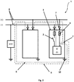
- Fig. 2 illustrates the present invention comprising a functional switching device 2 in a negative pole of a storage bus line of an energy storage unit 3, a short-circuit F, an overcurrent device 4, a voltage limiting device VLD, a short-circuit big loop 5 and a small loop 6, an additional disconnector 7, and ground connection 10.
- the functional switching device 2 is moved to the negative pole of the storage bus line of the energy storage unit 3.
- the switching device 2 is loaded only by one energy storage unit 3 prospective current which is not high enough to damage it, e.g. weld or burn out contacts points of the switching device 2 before the overcurrent device 4 will operate.
- the positive pole of the storage bus line of the energy storage unit 3 will be interrupted by the overcurrent device 4 (e.g. fuse-link).
- a disconnector function can be realized by a withdrawable part 7 of the energy storage system.
- Fig. 3 illustrates the present invention according to another embodiment comprising a functional switching device 2 in a negative pole of an energy storage unit 3, a short-circuit F, an overcurrent device 4, a short-circuit big loop 5 and a small loop 6, an additional disconnector 7.
- the switching device 2 according to the present invention and the energy storage unit 3 has no grounding 10 and no voltage limiting device VLD.
Landscapes
- Engineering & Computer Science (AREA)
- Power Engineering (AREA)
- Life Sciences & Earth Sciences (AREA)
- Sustainable Development (AREA)
- Sustainable Energy (AREA)
- Transportation (AREA)
- Mechanical Engineering (AREA)
- Charge And Discharge Circuits For Batteries Or The Like (AREA)
Priority Applications (1)
| Application Number | Priority Date | Filing Date | Title |
|---|---|---|---|
| EP19187719.0A EP3769998A1 (fr) | 2019-07-23 | 2019-07-23 | Circuit de commutation pour un système de stockage d'énergie stationnaire à chemin de fer dc |
Applications Claiming Priority (1)
| Application Number | Priority Date | Filing Date | Title |
|---|---|---|---|
| EP19187719.0A EP3769998A1 (fr) | 2019-07-23 | 2019-07-23 | Circuit de commutation pour un système de stockage d'énergie stationnaire à chemin de fer dc |
Publications (1)
| Publication Number | Publication Date |
|---|---|
| EP3769998A1 true EP3769998A1 (fr) | 2021-01-27 |
Family
ID=67438488
Family Applications (1)
| Application Number | Title | Priority Date | Filing Date |
|---|---|---|---|
| EP19187719.0A Withdrawn EP3769998A1 (fr) | 2019-07-23 | 2019-07-23 | Circuit de commutation pour un système de stockage d'énergie stationnaire à chemin de fer dc |
Country Status (1)
| Country | Link |
|---|---|
| EP (1) | EP3769998A1 (fr) |
Citations (7)
| Publication number | Priority date | Publication date | Assignee | Title |
|---|---|---|---|---|
| US7772806B2 (en) | 2006-04-11 | 2010-08-10 | Mitsubishi Electric Corporation | Power storage system |
| WO2012164232A2 (fr) | 2011-05-31 | 2012-12-06 | Adetel Equipment | Système de stockage d'énergie capacitif |
| JP2013090474A (ja) * | 2011-10-19 | 2013-05-13 | Toyota Motor Corp | 蓄電システム及び電流センサ異常を検出する方法 |
| CN104319832A (zh) | 2014-10-13 | 2015-01-28 | 株洲时代装备技术有限责任公司 | 一种用于超级电容储能式有轨电车的地面成套充电装置 |
| US20170326999A1 (en) * | 2015-04-15 | 2017-11-16 | Mitsubishi Electric Corporation | Vehicle power supply device |
| EP3290256A1 (fr) * | 2016-08-23 | 2018-03-07 | GS Yuasa International Ltd. | Dispositif de détection de surintensité, appareil de stockage d'énergie et procédé de détection de courant |
| WO2018100531A1 (fr) * | 2016-11-30 | 2018-06-07 | Bombardier Recreational Products Inc. | Système électrique et procédé d'excitation du système électrique |
-
2019
- 2019-07-23 EP EP19187719.0A patent/EP3769998A1/fr not_active Withdrawn
Patent Citations (7)
| Publication number | Priority date | Publication date | Assignee | Title |
|---|---|---|---|---|
| US7772806B2 (en) | 2006-04-11 | 2010-08-10 | Mitsubishi Electric Corporation | Power storage system |
| WO2012164232A2 (fr) | 2011-05-31 | 2012-12-06 | Adetel Equipment | Système de stockage d'énergie capacitif |
| JP2013090474A (ja) * | 2011-10-19 | 2013-05-13 | Toyota Motor Corp | 蓄電システム及び電流センサ異常を検出する方法 |
| CN104319832A (zh) | 2014-10-13 | 2015-01-28 | 株洲时代装备技术有限责任公司 | 一种用于超级电容储能式有轨电车的地面成套充电装置 |
| US20170326999A1 (en) * | 2015-04-15 | 2017-11-16 | Mitsubishi Electric Corporation | Vehicle power supply device |
| EP3290256A1 (fr) * | 2016-08-23 | 2018-03-07 | GS Yuasa International Ltd. | Dispositif de détection de surintensité, appareil de stockage d'énergie et procédé de détection de courant |
| WO2018100531A1 (fr) * | 2016-11-30 | 2018-06-07 | Bombardier Recreational Products Inc. | Système électrique et procédé d'excitation du système électrique |
Similar Documents
| Publication | Publication Date | Title |
|---|---|---|
| EP3872944A1 (fr) | Dispositif de dissipation d'énergie à courant continu et son procédé de commande | |
| AU2018241039B2 (en) | Converter configuration for an electricity charging station and corresponding electricity charging station | |
| CN108391456B (zh) | 电源系统 | |
| JP6178328B2 (ja) | 電気化学セルを含むdc電圧源 | |
| CN1816462B (zh) | 牵引整流器的过电压限幅器 | |
| US9550434B2 (en) | Energy management system and method for a vehicle | |
| US20190016224A1 (en) | Power electronic system for an electricity charging station and corresponding electricity charging station | |
| KR102786652B1 (ko) | 충전 스테이션 배리스터에 의해 야기된 결함 전류를 차단하기 위해 트랜지스터와 역 다이오드를 포함하는 dc 차량 충전 회로 | |
| JP4415874B2 (ja) | 交通システムの充放電方法 | |
| JP6829069B2 (ja) | 鉄道車両用回路システム | |
| AU2018241040B2 (en) | Use of two dc/dc controllers in the power electronics system of a charging station or electricity charging station | |
| CN117500684A (zh) | 用于执行车辆的车载电网的预充电过程的方法和用于车辆的车载电网 | |
| US10056841B2 (en) | Energy storage arrangement, energy storage system and method for operating an energy storage arrangement | |
| CN107431365A (zh) | 蓄电装置 | |
| CN104908604A (zh) | 机载电网 | |
| CN106660458B (zh) | 用于具有电驱动装置或混合动力驱动装置的机动车的能量供给系统 | |
| EP3769998A1 (fr) | Circuit de commutation pour un système de stockage d'énergie stationnaire à chemin de fer dc | |
| CN101842960B (zh) | 用于电气传动系统的电储能器 | |
| CN111497621A (zh) | 一种无轨电车分线器控制电路、控制系统及其工作方法 | |
| CN207825948U (zh) | 开关电路及电源分配电路 | |
| JP2010040348A (ja) | 直流電源の開閉方法とその装置 | |
| CN113954641B (zh) | 城轨列车高压母线电路 | |
| CN117458952A (zh) | 具有他励同步电机的机动车 | |
| CN116001585A (zh) | 储能式有轨电车及其储能电源充电控制系统、方法 | |
| CN109818500B (zh) | 一种集成式高压电器设备 |
Legal Events
| Date | Code | Title | Description |
|---|---|---|---|
| PUAI | Public reference made under article 153(3) epc to a published international application that has entered the european phase |
Free format text: ORIGINAL CODE: 0009012 |
|
| STAA | Information on the status of an ep patent application or granted ep patent |
Free format text: STATUS: THE APPLICATION HAS BEEN PUBLISHED |
|
| AK | Designated contracting states |
Kind code of ref document: A1 Designated state(s): AL AT BE BG CH CY CZ DE DK EE ES FI FR GB GR HR HU IE IS IT LI LT LU LV MC MK MT NL NO PL PT RO RS SE SI SK SM TR |
|
| AX | Request for extension of the european patent |
Extension state: BA ME |
|
| STAA | Information on the status of an ep patent application or granted ep patent |
Free format text: STATUS: THE APPLICATION IS DEEMED TO BE WITHDRAWN |
|
| 18D | Application deemed to be withdrawn |
Effective date: 20210728 |