EP3770038A1 - Schienenfahrzeugkupplung - Google Patents
Schienenfahrzeugkupplung Download PDFInfo
- Publication number
- EP3770038A1 EP3770038A1 EP20185968.3A EP20185968A EP3770038A1 EP 3770038 A1 EP3770038 A1 EP 3770038A1 EP 20185968 A EP20185968 A EP 20185968A EP 3770038 A1 EP3770038 A1 EP 3770038A1
- Authority
- EP
- European Patent Office
- Prior art keywords
- bolt
- rail vehicle
- bearing
- vehicle coupling
- joint
- Prior art date
- Legal status (The legal status is an assumption and is not a legal conclusion. Google has not performed a legal analysis and makes no representation as to the accuracy of the status listed.)
- Granted
Links
Images

Classifications
-
- B—PERFORMING OPERATIONS; TRANSPORTING
- B61—RAILWAYS
- B61G—COUPLINGS; DRAUGHT AND BUFFING APPLIANCES
- B61G5/00—Couplings for special purposes not otherwise provided for
- B61G5/02—Couplings for special purposes not otherwise provided for for coupling articulated trains, locomotives and tenders or the bogies of a vehicle; Coupling by means of a single coupling bar; Couplings preventing or limiting relative lateral movement of vehicles
Definitions
- the invention relates to a rail vehicle coupling.
- Certain types of rail vehicles such as trams or underground trains, run in fixed train compositions and are not operationally separated. These vehicles often have special configurations in which each individual vehicle is not equipped with a chassis, but is carried by the neighboring vehicles as a so-called sedan trolley or is partly carried by one of the neighboring vehicles as a trailer vehicle.
- a special coupling is provided between a conventional and a litter wagon or a trailer vehicle, which transmits the operating and weight forces and which ensures the necessary mobility for cornering, hilltop and tub travel.
- Ball joints (spherical bearings) or elastomer layer spring bearings are particularly well suited for this, but must be supplemented with suitable anti-roll supports.
- the invention is therefore based on the object of specifying a rail vehicle coupling with a spherical bearing in which the bolt of the bearing can be easily installed or removed; in particular, minimal inaccuracies in the positioning of the two halves of the coupling should not make it difficult to insert the bolt.
- a rail vehicle coupling for connecting two rail vehicles which has a hinge eye set up for detachable connection to one of the two rail vehicles and a hinge fork set up for detachable connection with the other of the two rail vehicles, as well as a horizontally aligned bolt, which connects to the joint fork can be connected and which comprises a spherical bearing connected to the joint eye, each end of the bolt being connected to the joint yoke via an elastic bearing ring.
- the elastic bearing ring is designed as a three-part component, comprising a conical metallic inner ring with a cylindrical bore and a conical metallic outer ring with a conical bore and an elastic intermediate layer between the inner ring and the outer ring.
- the corresponding bores in the joint fork are also to be conical.
- An elastic bearing ring must be provided at both ends of the bolt, which is pushed onto the respective bolt end after the bolt has been inserted into the spherical bearing. Small eccentricities of the bolt with respect to the bores in the joint fork are absorbed by the elastic intermediate layer of the elastic bearing ring. It is thus possible, even if the bores in the joint fork are not completely aligned with the bolt, to introduce this bolt into the rail vehicle coupling.
- a clamping cover is to be arranged at each end of the bolt, which fixes the inner rings of the bearing rings to the bolt by means of a screw connection. It is possible to implement this screw connection with threads in the bolt or to realize it by means of a pull rod which is guided inside a hollow bolt.
- At least one sleeve is to be provided which connects the bolt between the spherical bearing and one of the bearing rings includes.
- the length of this sleeve determines the position of the inner bearing ring in relation to the spherical bearing.
- One of the sleeves can be replaced by a shoulder on the bolt, but this restricts the joining direction of the bolt.
- an outer clamping cover to be arranged at each end of the bolt, which fixes the outer rings of the bearing rings to the joint fork by means of a screw connection. In this way, the bores in the joint fork can be closed and the bearing rings can be protected from contamination.
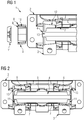
- Fig.1 shows an example and schematically a detail of a rail vehicle coupling.
- a section through a rail vehicle coupling 1 comprising a hinge eye 2 with a spherical bearing 5 arranged therein is shown.
- the section runs through the center of the spherical bearing 5, along the bolt 4 penetrating the spherical bearing 5 one half of the rail vehicle coupling 1 is shown, the second half is designed as a mirror image.
- the joint eye 2 is equipped with bores for producing a screw connection with a rail vehicle and has a shape in which the spherical bearing 5 is arranged.
- the spherical bearing is penetrated by a bolt 4, the ends of which are each supported in a joint fork 3.
- the combination of a joint eye 2 with a spherical bearing 5, a joint fork 3 and a bolt 4 forms a rail vehicle coupling with three degrees of freedom of rotation, as can be used, for example, at the coupling point between a sedan trolley and a conventional trolley.
- the rail vehicle coupling 1 is shown in a partially disassembled state, the bolt 4 is not connected to the joint fork 3, the corresponding connecting elements are shown in their relative installation position to the bolt 4 in the manner of the exploded view.
- this connection takes place by means of an elastic bearing ring 6.
- This elastic bearing ring 6 comprises an inner ring 8, an outer ring 9 and an elastic intermediate layer 10, which is arranged between the inner ring 8 and the outer ring 9.
- the inner diameter of the inner ring 8 is designed so that it can be pushed onto the bolt 4, with a sleeve 7 surrounding the bolt 4 specifying the required distance between the inner ring 8 and the spherical bearing 5 in its installed position.
- the outer contour of the inner ring 8 is conical, as is the inner contour of the outer ring 9, so that the elastic intermediate layer 10 essentially assumes a frustoconical shape with a conical bore.
- a conical bore 12 for receiving the elastic bearing ring 6, more precisely the outer ring 9, is arranged in the joint fork 3.
- the joint fork 3 and the joint eye 2 with the spherical bearing 5 are brought into their relative assembly position and the bolt 4 is introduced into the spherical bearing 5.
- the latter can be done very easily, since the ends of the bolt 4 do not have to be inserted into fits on the joint fork 3, but have a large free space and the positioning of the joint fork 3 to the joint eye 2 does not have to be done with the same accuracy as with conventional rail vehicle couplings.
- the sleeves 7 are then pushed onto the bolt 4 and the elastic bearing rings 6.
- the conical bore 12 centers the bolt 4 in the conical bore 12 when the elastic bearing rings 6 are pushed onto the bolt 4 in the direction of the spherical bearing 5.
- the end position of the inner ring 8 is determined by the sleeve 7.
- a clamping cover 11 fixes the inner ring 8 on the bolt 4, wherein in the exemplary embodiment shown a screw connection guided through a bore 13, which connects the clamping cover 11 on both sides, can be used.
- the clamping cover 11 can also be releasably fastened by means of a thread located on a shoulder of the bolt 4.
- Fig. 2 shows an example and schematically a rail vehicle coupling.
- the rail vehicle coupling 1 is off Fig.1 shown, the section through the entire rail vehicle coupling 1 is shown and all components are shown in their installed position.
- the elastic bearing rings 6 are in their end positions predetermined by the sleeves 7 and are fixed by clamping covers 11.
- outer clamping covers 13 are arranged at the ends of the bolt 4 and prevent the elastic bearing rings 6 from loosening in the conical bores of the joint fork 3.
- the outer clamping covers 13 can be releasably attached to the joint fork 3 by means of screw connections.
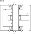
- Fig. 3 shows an example and schematically a rail vehicle coupling with bearing rings in the X position.
- a highly abstract sectional illustration through a rail vehicle coupling 1 with a joint fork 3, a joint eye 2 with a spherical bearing 5 and a bolt 4 penetrating the spherical bearing 5 is shown.
- the ends of the bolt 4 are fastened in elastic bearing rings 6 in conical bores in the joint fork 3.
- a horizontal section through the center point of the spherical bearing 5 is shown.
- the elastic bearing rings 6 are each fixed to the bolt 4 by means of a clamping cover 11.
- a screw connection with the bolt 4 is provided for this purpose.
- the internal structure of the elastic bearing rings 6 shows an X-shaped structure in this sectional view.
- Fig. 4 shows an example and schematically a rail vehicle coupling with bearing rings in the O-position. It is a rail vehicle coupling 1 as in FIG Fig. 3 shown, which differs in the structure of the elastic bearing rings 6.
- the course of the elastic intermediate layer is designed in such a way that its diameter increases in the direction of the spherical bearing; the inner structure of the elastic bearing rings 6 shows an O-shaped structure in this sectional illustration.
- This embodiment requires the use of an outer clamping cover 14 in order to prevent the elastic bearing rings from becoming loose.
- the outer clamping covers 14 are detachably connected to the joint fork 3 by means of screw connections.
Landscapes
- Engineering & Computer Science (AREA)
- Mechanical Engineering (AREA)
- Pivots And Pivotal Connections (AREA)
Abstract
Description
- Die Erfindung betrifft eine Schienenfahrzeugkupplung.
- Bestimmte Typen von Schienenfahrzeugen, wie Straßenbahnen oder U-Bahnen verkehren in festen Zugzusammenstellungen und werden betriebsmäßig nicht getrennt. Dabei weisen diese Fahrzeuge auch oft spezielle Konfigurationen auf, bei welchen nicht jedes einzelne Fahrzeug mit einem Fahrwerk ausgestattet ist, sondern als sogenannter Sänftenwagen von den benachbarten Fahrzeugen getragen wird, bzw. als Aufliegerfahrzeug teilweise von einem der benachbarten Fahrzeuge getragen wird. Zwischen einem konventionellen und einem Sänftenwagen oder einem Aufliegerfahrzeug ist eine besondere Kupplung vorgesehen, welche die Betriebs- und Gewichtskräfte übermittelt und welche die erforderliche Beweglichkeit für Kurven- Kuppen- und Wannenfahrten sicherstellt. Dafür sind insbesondere Kugelgelenke (Sphärolager) oder Elastomer-Schichtfederlager gut geeignet, sind jedoch um geeignete Wankstützen zu ergänzen. Diese Wankstützen verhindern ein Verkippen um die Längsachse der gekoppelten Wagen zueinander, behindern die weiteren Freiheitsgrade jedoch nicht. Eine Wartung dieser Kugelgelenke kann jedoch nur erfolgen, wenn die Kuppelstelle zwischen einem konventionellen Wagen und einem Sänftenwagen getrennt ist. Dabei ist der Sänftenwagen, da er kein Drehgestell umfasst, geeignet anzuheben und abzustützen. Diese Tätigkeit ist auch in einer gut ausgerüsteten Schienenfahrzeugwerkstatt ein umfangreiches, aufwendiges und somit teures Vorhaben, sodass dafür Erleichterungen geschaffen wurden. In der Patentschrift
AT 519362 B1 - Der Erfindung liegt daher die Aufgabe zugrunde, eine Schienenfahrzeugkupplung mit einem Sphärolager anzugeben, bei welcher ein Ein- bzw. Ausbau des Bolzens des Lagers einfach möglich ist, insbesondere sollen minimale Ungenauigkeiten der Positionierung der beiden Hälften der Kupplung zueinander das Einbringen des Bolzens nicht erschweren.
- Die Aufgabe wird durch eine Schienenfahrzeugkupplung mit den Merkmalen des Anspruchs 1 gelöst. Vorteilhafte Ausgestaltungen sind Gegenstand untergeordneter Ansprüche.
- Dem Grundgedanken der Erfindung nach wird eine Schienenfahrzeugkupplung für die Verbindung zweier Schienenfahrzeuge beschrieben, welche ein zur lösbaren Verbindung mit einem der beiden Schienenfahrzeuge eingerichtetes Gelenkauge und eine zur lösbaren Verbindung mit dem weiteren der beiden Schienenfahrzeuge eingerichtete Gelenkgabel sowie einen waagrecht ausgerichteten Bolzen, welche mit der Gelenkgabel verbindbar ist und welche ein mit dem Gelenkauge verbundenes Sphärolager durchdringt umfasst, wobei jedes Ende des Bolzens über je einen elastischen Lagerring mit der Gelenkgabel verbunden ist.
- Dadurch ist der Vorteil erzielbar, das Schließen des Gelenks deutlich einfacher zu gestalten als bei Schienenfahrzeugkupplungen gemäß dem Stand der Technik. Konventionelle Gelenke bedürfen einer optimalen Ausrichtung der Bohrungen in der Gelenkgabel und in dem Sphärolager, um den Bolzen einbringen zu können. Selbst kleine Ungenauigkeiten in dieser Ausrichtung führen dazu, dass der Bolzen nicht, bzw. nur mit übermäßigem Kraftaufwand eingebracht werden kann. Gegenständliche Erfindung ermöglicht es, auch bei nicht idealer Fluchtung dieser Bohrungen, den Bolzen einbringen zu können, da zwischen der Innenwandung der Bohrungen in der Gelenkgabel und dem Bolzen ein Zwischenraum besteht, sodass bei der Gelenkmontage in einem ersten Schritt der Bolzen in das Sphärolager eingebracht wird. Der genannte Zwischenraum wird bei der weiteren Montage jeweils mit einem elastischen Lagerring mit der Gelenkgabel verbunden.
- Der elastische Lagerring ist als dreiteiliger Bauteil, umfassend einen konusförmigen metallischen Innenring mit zylindrischer Bohrung und einen konusförmigen metallischen Außenring mit konischer Bohrung und einer elastischen Zwischenschicht zwischen dem Innenring und dem Außenring ausgeführt. Die korrespondierenden Bohrungen in der Gelenkgabel sind dabei ebenfalls konusförmig auszuführen.
- Es ist an beiden Enden des Bolzens je ein elastischer Lagerring vorzusehen, welcher nach dem Einbringen des Bolzens in das Sphärolager auf das jeweilige Bolzenende geschoben wird. Dabei werden kleine Exzentrizitäten des Bolzens gegenüber den Bohrungen in der Gelenkgabel von der elastischen Zwischenschicht des elastischen Lagerrings aufgenommen. Somit gelingt es, auch bei nicht vollständiger Fluchtung der Bohrungen in der Gelenkgabel mit dem Bolzen, diesen Bolzen in die Schienenfahrzeugkupplung einzubringen.
- Es ist vorteilhaft, die Lagerringe axial in Richtung des Mittelpunkts des Sphärolagers in ihrer Einbauposition zu spannen, sodass eine Lockerung der Lagerringe und damit auch des Bolzens verhindert werden kann. Dazu ist an jedem Ende des Bolzens ein Spanndeckel anzuordnen, welcher die Innenringe der Lagerringe mittels einer Schraubverbindung an dem Bolzen fixiert.
Es ist möglich, diese Schraubverbindung mit Gewinden im Bolzen auszuführen oder mittels einer Zugstange zu realisieren, welche im Inneren eines hohl gebohrten Bolzens geführt wird. - Um eine definierte Position der Innenringe an dem Bolzen zu erzielen, ist mindestens eine Hülse vorzusehen, welche den Bolzen zwischen dem Sphärolager und einem der Lagerringe umfasst. Die Länge dieser Hülse bestimmt die Position des inneren Lagerrings in Bezug auf das Sphärolager. Es kann eine der Hülsen durch einen Ansatz an dem Bolzen ersetzt werden, wodurch jedoch die Fügerichtung des Bolzens eingeschränkt wird.
- In weiterer Fortbildung der Erfindung ist vorgesehen, an jedem Ende des Bolzens einen äußeren Spanndeckel anzuordnen, welcher die Außenringe der Lagerringe mittels einer Schraubverbindung an der Gelenkgabel fixiert. Solcherart können die Bohrungen in der Gelenkgabel verschlossen und die Lagerringe vor Verschmutzung geschützt werden.
- Es zeigen beispielhaft:
- Fig.1
- Schienenfahrzeugkupplung, Detail.
- Fig.2
- Schienenfahrzeugkupplung.
- Fig.3
- Schienenfahrzeugkupplung, Lagerringe in X-Stellung.
- Fig.4
- Schienenfahrzeugkupplung, Lagerringe in O-Stellung.
-
Fig.1 zeigt beispielhaft und schematisch ein Detail einer Schienenfahrzeugkupplung. Es ist ein Schnitt durch eine Schienenfahrzeugkupplung 1, umfassend ein Gelenkauge 2 mit einem darin angeordneten Sphärolager 5 dargestellt. Der Schnitt verläuft durch den Mittelpunkt des Sphärolagers 5, entlang dem das Sphärolager 5 durchdringenden Bolzen 4. Es ist eine Hälfte der Schienenfahrzugskupplung 1 dargestellt, die zweite Hälfte ist dazu spiegelbildlich ausgebildet. Das Gelenkauge 2 ist mit Bohrungen zur Herstellung einer Schraubverbindung mit einem Schienenfahrzeug ausgestattet und weist eine Ausformung auf, in welcher das Sphärolager 5 angeordnet ist. Das Sphärolager ist von einem Bolzen 4 durchdrungen, deren Enden jeweils in einer Gelenkgabel 3 gelagert sind. Die Zusammenstellung aus einem Gelenkauge 2 mit einem Sphärolager 5, einer Gelenkgabel 3 und einem Bolzen 4 bildet eine Schienenfahrzeugkupplung mit drei Rotationsfreiheitsgraden, wie sie beispielsweise an der Kuppelstelle zwischen einem Sänftenwagen und einem konventionellen Wagen zum Einsatz kommen kann. Die Schienenfahrzeugkupplung 1 ist in teilweise zerlegtem Zustand dargestellt, der Bolzen 4 ist nicht mit der Gelenkgabel 3 verbunden, die entsprechenden Verbindungselemente sind nach Art der Explosionszeichnung in ihrer relativen Einbaulage zu dem Bolzen 4 dargestellt. Erfindungsgemäß erfolgt diese Verbindung mittels eines elastischen Lagerrings 6. Dieser elastische Lagerring 6 umfasst einen Innenring 8, einen Außenring 9 und eine elastische Zwischenschicht 10, welche zwischen dem Innenring 8 und dem Außenring 9 angeordnet ist. Der Innendurchmesser des Innenrings 8 ist so gestaltet, dass er auf den Bolzen 4 schiebbar ist, wobei eine den Bolzen 4 umfassende Hülse 7 den erforderlichen Abstand des Innenrings 8 zu dem Sphärolager 5 in seiner Einbauposition vorgibt. Die Außenkontur des Innenrings 8 ist konisch ausgeführt, ebenso die Innenkontur des Außenrings 9, sodass die elastische Zwischenschicht 10 im Wesentlichen eine kegelstumpfartige Form mit einer kegeligen Bohrung annimmt. In der Gelenkgabel 3 ist eine konische Bohrung 12 zur Aufnahme des elastischen Lagerrings 6, genauer des Außenrings 9 angeordnet. Bei der Montage, d.h. dem Schließen der Schienenfahrzeugkupplung 1 werden in einem ersten Schritt die Gelenkgabel 3 und das Gelenkauge 2 mit dem Sphärolager 5 in ihre relative Montageposition gebracht und der Bolzen 4 in das Sphärolager 5 eingebracht. Letzteres kann sehr einfach erfolgen, da die Enden des Bolzens 4 dabei nicht in Passungen an der Gelenkgabel 3 eingeführt werden müssen, sondern einen großen Freiraum besitzen und die Positionierung der Gelenkgabel 3 zu dem Gelenkauge 2 nicht mit jener Genauigkeit erfolgen muß wie bei herkömmlichen Schienenfahrzeugkupplungen. In weiterer Folge werden die Hülsen 7 auf den Bolzen 4 geschoben sowie die elastischen Lagerringe 6. Die konische Bohrung 12 bewirkt eine Zentrierung des Bolzens 4 in der konischen Bohrung 12 wenn die elastischen Lagerringe 6 in Richtung des Sphärolagers 5 auf den Bolzen 4 geschoben werden. Die Endposition des Innenrings 8 ist dabei durch die Hülse 7 bestimmt. Ein Spanndeckel 11 fixiert den Innenring 8 auf dem Bolzen 4, wobei in gezeigtem Ausführungsbeispiel eine durch eine Bohrung 13 geführte Schraubverbindung, welche die Spanndeckel 11 beider Seiten verbindet, einsetzbar ist. Ebenso kann der Spanndeckel 11 mittels eines auf einem Ansatz des Bolzens 4 befindlichen Gewindes lösbar befestigt werden. -
Fig.2 zeigt beispielhaft und schematisch eine Schienenfahrzeugkupplung. Es ist die Schienenfahrzeugkupplung 1 ausFig.1 dargestellt, wobei der Schnitt durch die gesamte Schienenfahrzeugkupplung 1 gezeigt ist und wobei alle Bauteile in ihrer Einbauposition gezeigt sind. Die elastischen Lagerringe 6 befinden sich in ihren, durch die Hülsen 7 vorgegebenen Endpositionen und werden durch Spanndeckel 11 fixiert. Weiters sind äußere Spanndeckel 13 an den Enden des Bolzens 4 angeordnet und verhindern ein Lockerwerden der elastischen Lagerringe 6 in den konischen Bohrungen der Gelenkgabel 3. Die äußeren Spanndeckel 13 können mittels Schraubverbindungen an der Gelenkgabel 3 lösbar befestigt werden. -
Fig.3 zeigt beispielhaft und schematisch eine Schienenfahrzeugkupplung mit Lagerringen in X-Stellung. Es ist eine stark abstrahierte Schnittdarstellung durch eine Schienenfahrzeugkupplung 1 mit einer Gelenkgabel 3, einem Gelenkauge 2 mit einem Sphärolager 5 und einen das Sphärolager 5 durchdringenden Bolzen 4 dargestellt. Die Enden des Bolzens 4 sind in elastischen Lagerringen 6 in konischen Bohrungen in der Gelenkgabel 3 befestigt. Es ist ein horizontaler Schnitt durch den Mittelpunkt des Sphärolagers 5 gezeigt. Die elastischen Lagerringe 6 sind mittels je einem Spanndeckel 11 an dem Bolzen 4 fixiert. Dazu ist eine Schraubverbindung mit dem Bolzen 4 vorgesehen. Der innere Aufbau der elastischen Lagerringe 6 zeigt in dieser Schnittdarstellung eine X-förmige Struktur. -
Fig.4 zeigt beispielhaft und schematisch eine Schienenfahrzeugkupplung mit Lagerringen in O-Stellung. Es ist eine Schienenfahrzeugkupplung 1 wie inFig.3 dargestellt, welche sich im Aufbau der elastischen Lagerringe 6 unterscheidet. In diesem Ausführungsbeispiel ist der Verlauf der elastischen Zwischenschicht so gestaltet, dass deren Durchmesser in Richtung des Sphärolagers hin zunimmt, der innere Aufbau der elastischen Lagerringe 6 zeigt in dieser Schnittdarstellung eine O-förmige Struktur. Diese Ausführungsform bedingt es, einen äußeren Spanndeckel 14 einzusetzen, um ein Lockerwerden der elastischen Lagerringe zu verhindern. Die äußeren Spanndeckel 14 sind dabei mittels Schraubverbindungen mit der Gelenkgabel 3 lösbar verbunden. -
- 1
- Schienenfahrzeugkupplung
- 2
- Gelenkauge
- 3
- Gelenkgabel
- 4
- Bolzen
- 5
- Sphärolager
- 6
- Elastischer Lagerring
- 7
- Hülse
- 8
- Innenring
- 9
- Außenring
- 10
- Elastische Zwischenschicht
- 11
- Spanndeckel
- 12
- Konische Bohrung
- 13
- Bohrung
- 14
- Äußerer Spanndeckel
Claims (5)
- Schienenfahrzeugkupplung (1) für die Verbindung zweier Schienenfahrzeuge, umfassend ein zur lösbaren Verbindung mit einem der beiden Schienenfahrzeuge eingerichtetes Gelenkauge (2) und eine zur lösbaren Verbindung mit dem weiteren der beiden Schienenfahrzeuge eingerichtete Gelenkgabel (3) sowie einen waagrecht ausgerichteten Bolzen (4), welche mit der Gelenkgabel (3) verbindbar ist und welche ein mit dem Gelenkauge (2) verbundenes Sphärolager (5) durchdringt,
dadurch gekennzeichnet, dass
jedes Ende des Bolzens (4) über je einen elastischen Lagerring (6) mit der Gelenkgabel verbunden ist. - Schienenfahrzeugkupplung (1) nach Anspruch 1,
dadurch gekennzeichnet, dass
mindestens eine Hülse (7) den Bolzen (4) zwischen dem Sphärolager (5) und einem Lagerring (6) umfasst. - Schienenfahrzeugkupplung (1) nach Anspruch 1 oder 2,
dadurch gekennzeichnet, dass
die Lagerringe (6) je einen konusförmigen metallischen Innenring (8) mit zylindrischer Bohrung und einen konusförmigen metallischen Außenring (9) mit konischer Bohrung aufweisen, wobei eine elastische Zwischenschicht (10) zwischen dem Innenring und dem Außenring angeordnet ist. - Schienenfahrzeugkupplung (1) nach einem der Ansprüche 1 bis 3,
dadurch gekennzeichnet, dass
an jedem Ende des Bolzens ein Spanndeckel (11) angeordnet ist, welcher die Innenringe (8) der Lagerringe (6) mittels einer Schraubverbindung an dem Bolzen (4) fixiert. - Schienenfahrzeugkupplung (1) nach einem der Ansprüche 1 bis 3,
dadurch gekennzeichnet, dass an jedem Ende des Bolzens (4) ein äußerer Spanndeckel (14) angeordnet ist,
welcher die Außenringe (9) der Lagerringe (6) mittels einer Schraubverbindung an der Gelenkgabel (3) fixiert
Applications Claiming Priority (1)
| Application Number | Priority Date | Filing Date | Title |
|---|---|---|---|
| ATA50661/2019A AT522331B1 (de) | 2019-07-22 | 2019-07-22 | Schienenfahrzeugkupplung |
Publications (2)
| Publication Number | Publication Date |
|---|---|
| EP3770038A1 true EP3770038A1 (de) | 2021-01-27 |
| EP3770038B1 EP3770038B1 (de) | 2022-09-14 |
Family
ID=71620307
Family Applications (1)
| Application Number | Title | Priority Date | Filing Date |
|---|---|---|---|
| EP20185968.3A Active EP3770038B1 (de) | 2019-07-22 | 2020-07-15 | Schienenfahrzeugkupplung |
Country Status (4)
| Country | Link |
|---|---|
| EP (1) | EP3770038B1 (de) |
| AT (1) | AT522331B1 (de) |
| ES (1) | ES2927691T3 (de) |
| PL (1) | PL3770038T3 (de) |
Cited By (2)
| Publication number | Priority date | Publication date | Assignee | Title |
|---|---|---|---|---|
| CN113305153A (zh) * | 2021-05-31 | 2021-08-27 | 安徽马钢重型机械制造有限公司 | 一种板带热轧线定宽压力机拉杆装置 |
| CN115056815A (zh) * | 2022-07-14 | 2022-09-16 | 株洲时代新材料科技股份有限公司 | 胶轮列车车端铰接机构 |
Citations (7)
| Publication number | Priority date | Publication date | Assignee | Title |
|---|---|---|---|---|
| EP1048544A1 (de) * | 1999-04-29 | 2000-11-02 | ALSTOM LHB GmbH | Gelenkverbindung für Fahrzeugeinheiten von Schienenfahrzeugen |
| EP1151905A2 (de) * | 2000-05-05 | 2001-11-07 | SCHARFENBERGKUPPLUNG GmbH & Co. KG | Vorrichtung zur gelenkigen Verbindung von Wagenkästen eines mehrgliedrigen Schienenfahrzeuges |
| WO2007082316A1 (en) * | 2006-01-09 | 2007-07-19 | Deebar Mining & Industrial Supplies Cc | A train |
| DE102006011425A1 (de) * | 2006-03-11 | 2007-09-13 | Schaeffler Kg | Gelenkkupplung für Schienenfahrzeuge |
| DE102006036245A1 (de) * | 2006-08-03 | 2008-02-07 | Schaeffler Kg | Gelenkkupplung für Schienenfahrzeuge |
| CN106004919A (zh) * | 2016-06-14 | 2016-10-12 | 湘电重型装备有限公司 | 一种工矿电机车的铰接装置 |
| AT519362B1 (de) | 2016-10-04 | 2018-06-15 | Siemens Ag Oesterreich | Schienenfahrzeugkupplung für die Verbindung zweier Schienenfahrzeuge |
-
2019
- 2019-07-22 AT ATA50661/2019A patent/AT522331B1/de not_active IP Right Cessation
-
2020
- 2020-07-15 EP EP20185968.3A patent/EP3770038B1/de active Active
- 2020-07-15 ES ES20185968T patent/ES2927691T3/es active Active
- 2020-07-15 PL PL20185968.3T patent/PL3770038T3/pl unknown
Patent Citations (7)
| Publication number | Priority date | Publication date | Assignee | Title |
|---|---|---|---|---|
| EP1048544A1 (de) * | 1999-04-29 | 2000-11-02 | ALSTOM LHB GmbH | Gelenkverbindung für Fahrzeugeinheiten von Schienenfahrzeugen |
| EP1151905A2 (de) * | 2000-05-05 | 2001-11-07 | SCHARFENBERGKUPPLUNG GmbH & Co. KG | Vorrichtung zur gelenkigen Verbindung von Wagenkästen eines mehrgliedrigen Schienenfahrzeuges |
| WO2007082316A1 (en) * | 2006-01-09 | 2007-07-19 | Deebar Mining & Industrial Supplies Cc | A train |
| DE102006011425A1 (de) * | 2006-03-11 | 2007-09-13 | Schaeffler Kg | Gelenkkupplung für Schienenfahrzeuge |
| DE102006036245A1 (de) * | 2006-08-03 | 2008-02-07 | Schaeffler Kg | Gelenkkupplung für Schienenfahrzeuge |
| CN106004919A (zh) * | 2016-06-14 | 2016-10-12 | 湘电重型装备有限公司 | 一种工矿电机车的铰接装置 |
| AT519362B1 (de) | 2016-10-04 | 2018-06-15 | Siemens Ag Oesterreich | Schienenfahrzeugkupplung für die Verbindung zweier Schienenfahrzeuge |
Cited By (3)
| Publication number | Priority date | Publication date | Assignee | Title |
|---|---|---|---|---|
| CN113305153A (zh) * | 2021-05-31 | 2021-08-27 | 安徽马钢重型机械制造有限公司 | 一种板带热轧线定宽压力机拉杆装置 |
| CN115056815A (zh) * | 2022-07-14 | 2022-09-16 | 株洲时代新材料科技股份有限公司 | 胶轮列车车端铰接机构 |
| CN115056815B (zh) * | 2022-07-14 | 2024-03-12 | 株洲时代新材料科技股份有限公司 | 胶轮列车车端铰接机构 |
Also Published As
| Publication number | Publication date |
|---|---|
| AT522331B1 (de) | 2020-10-15 |
| PL3770038T3 (pl) | 2023-01-16 |
| ES2927691T3 (es) | 2022-11-10 |
| AT522331A4 (de) | 2020-10-15 |
| EP3770038B1 (de) | 2022-09-14 |
Similar Documents
| Publication | Publication Date | Title |
|---|---|---|
| DE2701984C2 (de) | ||
| DE4121080A1 (de) | Kupplungsvorrichtung fuer die auf einem gemeinsamen drehgestell abgestuetzten enden zweier gelenkig miteinander verbundener fahrzeugeinheiten | |
| EP3770038B1 (de) | Schienenfahrzeugkupplung | |
| EP1996439B1 (de) | Gelenkkupplung für schienenfahrzeuge | |
| DE19543183A1 (de) | Lange Kupplung für Eisenbahnwagen | |
| EP1048544B1 (de) | Gelenkverbindung für Fahrzeugeinheiten von Schienenfahrzeugen | |
| EP2167362B1 (de) | Fahrzeug mit gelenkig verbundenen wagenkästen | |
| DE102008038059B4 (de) | Kupplung zum Kuppeln zweier vorzugsweise schienengebundener Fahrzeugeinheiten | |
| EP3504098B1 (de) | Schienenfahrzeugkupplung für die verbindung zweier schienenfahrzeuge | |
| DE102004056265A1 (de) | Buchse | |
| DD290849A5 (de) | Anordnung der achslager in einem laufwerk fuer schienenfahrzeuge | |
| DE102017110325A1 (de) | Vorrichtung zum lösbaren Verbinden der Endbereiche eines ersten und zweiten hohlzylindrischen Kraftübertragungselements | |
| DE102021109529A1 (de) | Gelenkverbindung und Verfahren zum beweglichen Koppeln einer ersten Komponente an einer zweiten Komponente | |
| DE2831186C2 (de) | Kugelgelenkige Rohrkupplung | |
| AT519744B1 (de) | Wanksteife Schienenfahrzeugkupplung | |
| EP1724176B1 (de) | Einrichtung zur gelenkigen Verbindung von Eisenbahnfahrzeugen | |
| DE1258674B (de) | Kreuzgelenkkupplung | |
| DE102017200728B3 (de) | Kupplungssystem für ein Schienenfahrzeug | |
| EP3390197B1 (de) | Schienenfahrzeugkupplung | |
| DE102007041647A1 (de) | Lagerbefestigung | |
| AT226767B (de) | Gelenkwagenverbindung | |
| DE3104342C2 (de) | Vorrichtung zum Verbinden zweier Rohrenden bei einer aus einer Vielzahl von einzelnen Rohrleitungsteilen zusammengesetzten Rohrleitung | |
| DD232468A1 (de) | Loesbare scharnieranordnung an faltbaren lukendeckeln fuer schiffsluken | |
| DE69421691T2 (de) | U-förmiges Verbindungsglied für eine spielfreie Zugstangenanordnung mit einem Kugelgelenk | |
| CH719336B1 (de) | Puffer, insbesondere für ein Schienenfahrzeug. |
Legal Events
| Date | Code | Title | Description |
|---|---|---|---|
| PUAI | Public reference made under article 153(3) epc to a published international application that has entered the european phase |
Free format text: ORIGINAL CODE: 0009012 |
|
| STAA | Information on the status of an ep patent application or granted ep patent |
Free format text: STATUS: THE APPLICATION HAS BEEN PUBLISHED |
|
| AK | Designated contracting states |
Kind code of ref document: A1 Designated state(s): AL AT BE BG CH CY CZ DE DK EE ES FI FR GB GR HR HU IE IS IT LI LT LU LV MC MK MT NL NO PL PT RO RS SE SI SK SM TR |
|
| AX | Request for extension of the european patent |
Extension state: BA ME |
|
| STAA | Information on the status of an ep patent application or granted ep patent |
Free format text: STATUS: REQUEST FOR EXAMINATION WAS MADE |
|
| 17P | Request for examination filed |
Effective date: 20210203 |
|
| RBV | Designated contracting states (corrected) |
Designated state(s): AL AT BE BG CH CY CZ DE DK EE ES FI FR GB GR HR HU IE IS IT LI LT LU LV MC MK MT NL NO PL PT RO RS SE SI SK SM TR |
|
| GRAP | Despatch of communication of intention to grant a patent |
Free format text: ORIGINAL CODE: EPIDOSNIGR1 |
|
| STAA | Information on the status of an ep patent application or granted ep patent |
Free format text: STATUS: GRANT OF PATENT IS INTENDED |
|
| INTG | Intention to grant announced |
Effective date: 20220512 |
|
| GRAS | Grant fee paid |
Free format text: ORIGINAL CODE: EPIDOSNIGR3 |
|
| GRAA | (expected) grant |
Free format text: ORIGINAL CODE: 0009210 |
|
| STAA | Information on the status of an ep patent application or granted ep patent |
Free format text: STATUS: THE PATENT HAS BEEN GRANTED |
|
| AK | Designated contracting states |
Kind code of ref document: B1 Designated state(s): AL AT BE BG CH CY CZ DE DK EE ES FI FR GB GR HR HU IE IS IT LI LT LU LV MC MK MT NL NO PL PT RO RS SE SI SK SM TR |
|
| REG | Reference to a national code |
Ref country code: GB Ref legal event code: FG4D Free format text: NOT ENGLISH |
|
| REG | Reference to a national code |
Ref country code: CH Ref legal event code: EP |
|
| REG | Reference to a national code |
Ref country code: DE Ref legal event code: R096 Ref document number: 502020001692 Country of ref document: DE |
|
| REG | Reference to a national code |
Ref country code: IE Ref legal event code: FG4D Free format text: LANGUAGE OF EP DOCUMENT: GERMAN |
|
| REG | Reference to a national code |
Ref country code: AT Ref legal event code: REF Ref document number: 1518530 Country of ref document: AT Kind code of ref document: T Effective date: 20221015 |
|
| REG | Reference to a national code |
Ref country code: LT Ref legal event code: MG9D |
|
| REG | Reference to a national code |
Ref country code: NL Ref legal event code: MP Effective date: 20220914 |
|
| PG25 | Lapsed in a contracting state [announced via postgrant information from national office to epo] |
Ref country code: SE Free format text: LAPSE BECAUSE OF FAILURE TO SUBMIT A TRANSLATION OF THE DESCRIPTION OR TO PAY THE FEE WITHIN THE PRESCRIBED TIME-LIMIT Effective date: 20220914 Ref country code: RS Free format text: LAPSE BECAUSE OF FAILURE TO SUBMIT A TRANSLATION OF THE DESCRIPTION OR TO PAY THE FEE WITHIN THE PRESCRIBED TIME-LIMIT Effective date: 20220914 Ref country code: NO Free format text: LAPSE BECAUSE OF FAILURE TO SUBMIT A TRANSLATION OF THE DESCRIPTION OR TO PAY THE FEE WITHIN THE PRESCRIBED TIME-LIMIT Effective date: 20221214 Ref country code: LV Free format text: LAPSE BECAUSE OF FAILURE TO SUBMIT A TRANSLATION OF THE DESCRIPTION OR TO PAY THE FEE WITHIN THE PRESCRIBED TIME-LIMIT Effective date: 20220914 Ref country code: LT Free format text: LAPSE BECAUSE OF FAILURE TO SUBMIT A TRANSLATION OF THE DESCRIPTION OR TO PAY THE FEE WITHIN THE PRESCRIBED TIME-LIMIT Effective date: 20220914 Ref country code: FI Free format text: LAPSE BECAUSE OF FAILURE TO SUBMIT A TRANSLATION OF THE DESCRIPTION OR TO PAY THE FEE WITHIN THE PRESCRIBED TIME-LIMIT Effective date: 20220914 |
|
| PG25 | Lapsed in a contracting state [announced via postgrant information from national office to epo] |
Ref country code: HR Free format text: LAPSE BECAUSE OF FAILURE TO SUBMIT A TRANSLATION OF THE DESCRIPTION OR TO PAY THE FEE WITHIN THE PRESCRIBED TIME-LIMIT Effective date: 20220914 Ref country code: GR Free format text: LAPSE BECAUSE OF FAILURE TO SUBMIT A TRANSLATION OF THE DESCRIPTION OR TO PAY THE FEE WITHIN THE PRESCRIBED TIME-LIMIT Effective date: 20221215 |
|
| PG25 | Lapsed in a contracting state [announced via postgrant information from national office to epo] |
Ref country code: SM Free format text: LAPSE BECAUSE OF FAILURE TO SUBMIT A TRANSLATION OF THE DESCRIPTION OR TO PAY THE FEE WITHIN THE PRESCRIBED TIME-LIMIT Effective date: 20220914 Ref country code: RO Free format text: LAPSE BECAUSE OF FAILURE TO SUBMIT A TRANSLATION OF THE DESCRIPTION OR TO PAY THE FEE WITHIN THE PRESCRIBED TIME-LIMIT Effective date: 20220914 Ref country code: PT Free format text: LAPSE BECAUSE OF FAILURE TO SUBMIT A TRANSLATION OF THE DESCRIPTION OR TO PAY THE FEE WITHIN THE PRESCRIBED TIME-LIMIT Effective date: 20230116 Ref country code: CZ Free format text: LAPSE BECAUSE OF FAILURE TO SUBMIT A TRANSLATION OF THE DESCRIPTION OR TO PAY THE FEE WITHIN THE PRESCRIBED TIME-LIMIT Effective date: 20220914 |
|
| PG25 | Lapsed in a contracting state [announced via postgrant information from national office to epo] |
Ref country code: SK Free format text: LAPSE BECAUSE OF FAILURE TO SUBMIT A TRANSLATION OF THE DESCRIPTION OR TO PAY THE FEE WITHIN THE PRESCRIBED TIME-LIMIT Effective date: 20220914 Ref country code: IS Free format text: LAPSE BECAUSE OF FAILURE TO SUBMIT A TRANSLATION OF THE DESCRIPTION OR TO PAY THE FEE WITHIN THE PRESCRIBED TIME-LIMIT Effective date: 20230114 Ref country code: EE Free format text: LAPSE BECAUSE OF FAILURE TO SUBMIT A TRANSLATION OF THE DESCRIPTION OR TO PAY THE FEE WITHIN THE PRESCRIBED TIME-LIMIT Effective date: 20220914 |
|
| REG | Reference to a national code |
Ref country code: DE Ref legal event code: R097 Ref document number: 502020001692 Country of ref document: DE |
|
| PG25 | Lapsed in a contracting state [announced via postgrant information from national office to epo] |
Ref country code: NL Free format text: LAPSE BECAUSE OF FAILURE TO SUBMIT A TRANSLATION OF THE DESCRIPTION OR TO PAY THE FEE WITHIN THE PRESCRIBED TIME-LIMIT Effective date: 20220914 Ref country code: AL Free format text: LAPSE BECAUSE OF FAILURE TO SUBMIT A TRANSLATION OF THE DESCRIPTION OR TO PAY THE FEE WITHIN THE PRESCRIBED TIME-LIMIT Effective date: 20220914 |
|
| PLBE | No opposition filed within time limit |
Free format text: ORIGINAL CODE: 0009261 |
|
| STAA | Information on the status of an ep patent application or granted ep patent |
Free format text: STATUS: NO OPPOSITION FILED WITHIN TIME LIMIT |
|
| PG25 | Lapsed in a contracting state [announced via postgrant information from national office to epo] |
Ref country code: DK Free format text: LAPSE BECAUSE OF FAILURE TO SUBMIT A TRANSLATION OF THE DESCRIPTION OR TO PAY THE FEE WITHIN THE PRESCRIBED TIME-LIMIT Effective date: 20220914 |
|
| 26N | No opposition filed |
Effective date: 20230615 |
|
| PG25 | Lapsed in a contracting state [announced via postgrant information from national office to epo] |
Ref country code: SI Free format text: LAPSE BECAUSE OF FAILURE TO SUBMIT A TRANSLATION OF THE DESCRIPTION OR TO PAY THE FEE WITHIN THE PRESCRIBED TIME-LIMIT Effective date: 20220914 |
|
| PG25 | Lapsed in a contracting state [announced via postgrant information from national office to epo] |
Ref country code: MC Free format text: LAPSE BECAUSE OF FAILURE TO SUBMIT A TRANSLATION OF THE DESCRIPTION OR TO PAY THE FEE WITHIN THE PRESCRIBED TIME-LIMIT Effective date: 20220914 |
|
| PG25 | Lapsed in a contracting state [announced via postgrant information from national office to epo] |
Ref country code: MC Free format text: LAPSE BECAUSE OF FAILURE TO SUBMIT A TRANSLATION OF THE DESCRIPTION OR TO PAY THE FEE WITHIN THE PRESCRIBED TIME-LIMIT Effective date: 20220914 |
|
| REG | Reference to a national code |
Ref country code: BE Ref legal event code: MM Effective date: 20230731 |
|
| PG25 | Lapsed in a contracting state [announced via postgrant information from national office to epo] |
Ref country code: LU Free format text: LAPSE BECAUSE OF NON-PAYMENT OF DUE FEES Effective date: 20230715 |
|
| PG25 | Lapsed in a contracting state [announced via postgrant information from national office to epo] |
Ref country code: LU Free format text: LAPSE BECAUSE OF NON-PAYMENT OF DUE FEES Effective date: 20230715 |
|
| REG | Reference to a national code |
Ref country code: IE Ref legal event code: MM4A |
|
| PG25 | Lapsed in a contracting state [announced via postgrant information from national office to epo] |
Ref country code: IT Free format text: LAPSE BECAUSE OF FAILURE TO SUBMIT A TRANSLATION OF THE DESCRIPTION OR TO PAY THE FEE WITHIN THE PRESCRIBED TIME-LIMIT Effective date: 20220914 Ref country code: BE Free format text: LAPSE BECAUSE OF NON-PAYMENT OF DUE FEES Effective date: 20230731 |
|
| PG25 | Lapsed in a contracting state [announced via postgrant information from national office to epo] |
Ref country code: IE Free format text: LAPSE BECAUSE OF NON-PAYMENT OF DUE FEES Effective date: 20230715 |
|
| PG25 | Lapsed in a contracting state [announced via postgrant information from national office to epo] |
Ref country code: IE Free format text: LAPSE BECAUSE OF NON-PAYMENT OF DUE FEES Effective date: 20230715 |
|
| PG25 | Lapsed in a contracting state [announced via postgrant information from national office to epo] |
Ref country code: BG Free format text: LAPSE BECAUSE OF FAILURE TO SUBMIT A TRANSLATION OF THE DESCRIPTION OR TO PAY THE FEE WITHIN THE PRESCRIBED TIME-LIMIT Effective date: 20220914 |
|
| PG25 | Lapsed in a contracting state [announced via postgrant information from national office to epo] |
Ref country code: BG Free format text: LAPSE BECAUSE OF FAILURE TO SUBMIT A TRANSLATION OF THE DESCRIPTION OR TO PAY THE FEE WITHIN THE PRESCRIBED TIME-LIMIT Effective date: 20220914 |
|
| PG25 | Lapsed in a contracting state [announced via postgrant information from national office to epo] |
Ref country code: CY Free format text: LAPSE BECAUSE OF FAILURE TO SUBMIT A TRANSLATION OF THE DESCRIPTION OR TO PAY THE FEE WITHIN THE PRESCRIBED TIME-LIMIT; INVALID AB INITIO Effective date: 20200715 |
|
| PG25 | Lapsed in a contracting state [announced via postgrant information from national office to epo] |
Ref country code: HU Free format text: LAPSE BECAUSE OF FAILURE TO SUBMIT A TRANSLATION OF THE DESCRIPTION OR TO PAY THE FEE WITHIN THE PRESCRIBED TIME-LIMIT; INVALID AB INITIO Effective date: 20200715 |
|
| REG | Reference to a national code |
Ref country code: CH Ref legal event code: U11 Free format text: ST27 STATUS EVENT CODE: U-0-0-U10-U11 (AS PROVIDED BY THE NATIONAL OFFICE) Effective date: 20251006 |
|
| PGFP | Annual fee paid to national office [announced via postgrant information from national office to epo] |
Ref country code: DE Payment date: 20250919 Year of fee payment: 6 |
|
| PGFP | Annual fee paid to national office [announced via postgrant information from national office to epo] |
Ref country code: PL Payment date: 20250703 Year of fee payment: 6 |
|
| PGFP | Annual fee paid to national office [announced via postgrant information from national office to epo] |
Ref country code: GB Payment date: 20250811 Year of fee payment: 6 |
|
| PGFP | Annual fee paid to national office [announced via postgrant information from national office to epo] |
Ref country code: AT Payment date: 20250606 Year of fee payment: 6 Ref country code: FR Payment date: 20250716 Year of fee payment: 6 |
|
| PG25 | Lapsed in a contracting state [announced via postgrant information from national office to epo] |
Ref country code: TR Free format text: LAPSE BECAUSE OF FAILURE TO SUBMIT A TRANSLATION OF THE DESCRIPTION OR TO PAY THE FEE WITHIN THE PRESCRIBED TIME-LIMIT Effective date: 20220914 |
|
| PGFP | Annual fee paid to national office [announced via postgrant information from national office to epo] |
Ref country code: CH Payment date: 20251006 Year of fee payment: 6 |
|
| PGFP | Annual fee paid to national office [announced via postgrant information from national office to epo] |
Ref country code: ES Payment date: 20251020 Year of fee payment: 6 |