EP3770058A1 - Dispositif de sécurité pour plongeur et appareil de sécurité comprenant ledit dispositif - Google Patents
Dispositif de sécurité pour plongeur et appareil de sécurité comprenant ledit dispositif Download PDFInfo
- Publication number
- EP3770058A1 EP3770058A1 EP19188102.8A EP19188102A EP3770058A1 EP 3770058 A1 EP3770058 A1 EP 3770058A1 EP 19188102 A EP19188102 A EP 19188102A EP 3770058 A1 EP3770058 A1 EP 3770058A1
- Authority
- EP
- European Patent Office
- Prior art keywords
- safety device
- diver
- holding element
- holding
- actuation element
- Prior art date
- Legal status (The legal status is an assumption and is not a legal conclusion. Google has not performed a legal analysis and makes no representation as to the accuracy of the status listed.)
- Withdrawn
Links
- 230000007246 mechanism Effects 0.000 claims description 22
- 230000009471 action Effects 0.000 claims description 13
- 230000004913 activation Effects 0.000 claims description 7
- 239000012528 membrane Substances 0.000 claims description 6
- 230000005540 biological transmission Effects 0.000 claims description 5
- 238000003780 insertion Methods 0.000 claims description 3
- 230000037431 insertion Effects 0.000 claims description 3
- 229910052760 oxygen Inorganic materials 0.000 claims description 3
- 230000002441 reversible effect Effects 0.000 claims description 2
- 206010042772 syncope Diseases 0.000 abstract description 14
- 208000024756 faint Diseases 0.000 abstract description 3
- 238000007654 immersion Methods 0.000 abstract description 2
- 239000007789 gas Substances 0.000 description 47
- 230000001681 protective effect Effects 0.000 description 10
- XLYOFNOQVPJJNP-UHFFFAOYSA-N water Substances O XLYOFNOQVPJJNP-UHFFFAOYSA-N 0.000 description 8
- IJGRMHOSHXDMSA-UHFFFAOYSA-N Atomic nitrogen Chemical compound N#N IJGRMHOSHXDMSA-UHFFFAOYSA-N 0.000 description 2
- 208000008784 apnea Diseases 0.000 description 2
- QVGXLLKOCUKJST-UHFFFAOYSA-N atomic oxygen Chemical compound [O] QVGXLLKOCUKJST-UHFFFAOYSA-N 0.000 description 2
- 239000008280 blood Substances 0.000 description 2
- 210000004369 blood Anatomy 0.000 description 2
- 230000006835 compression Effects 0.000 description 2
- 238000007906 compression Methods 0.000 description 2
- 238000006073 displacement reaction Methods 0.000 description 2
- 210000003205 muscle Anatomy 0.000 description 2
- 239000001301 oxygen Substances 0.000 description 2
- 206010013647 Drowning Diseases 0.000 description 1
- 230000003213 activating effect Effects 0.000 description 1
- 238000007792 addition Methods 0.000 description 1
- 239000003570 air Substances 0.000 description 1
- UBAZGMLMVVQSCD-UHFFFAOYSA-N carbon dioxide;molecular oxygen Chemical compound O=O.O=C=O UBAZGMLMVVQSCD-UHFFFAOYSA-N 0.000 description 1
- 238000005352 clarification Methods 0.000 description 1
- 230000002301 combined effect Effects 0.000 description 1
- 230000001419 dependent effect Effects 0.000 description 1
- 230000000694 effects Effects 0.000 description 1
- 239000012530 fluid Substances 0.000 description 1
- 230000005802 health problem Effects 0.000 description 1
- 230000002706 hydrostatic effect Effects 0.000 description 1
- 230000008595 infiltration Effects 0.000 description 1
- 238000001764 infiltration Methods 0.000 description 1
- 239000000203 mixture Substances 0.000 description 1
- 238000012986 modification Methods 0.000 description 1
- 230000004048 modification Effects 0.000 description 1
- 229910052757 nitrogen Inorganic materials 0.000 description 1
- 230000002035 prolonged effect Effects 0.000 description 1
- 230000029058 respiratory gaseous exchange Effects 0.000 description 1
- 230000000284 resting effect Effects 0.000 description 1
- 238000004804 winding Methods 0.000 description 1
Images



Classifications
-
- B—PERFORMING OPERATIONS; TRANSPORTING
- B63—SHIPS OR OTHER WATERBORNE VESSELS; RELATED EQUIPMENT
- B63C—LAUNCHING, HAULING-OUT, OR DRY-DOCKING OF VESSELS; LIFE-SAVING IN WATER; EQUIPMENT FOR DWELLING OR WORKING UNDER WATER; MEANS FOR SALVAGING OR SEARCHING FOR UNDERWATER OBJECTS
- B63C9/00—Life-saving in water
- B63C9/08—Life-buoys, e.g. rings; Life-belts, jackets, suits, or the like
- B63C9/13—Life-buoys, e.g. rings; Life-belts, jackets, suits, or the like attachable to body member, e.g. arm, neck, head or waist
- B63C9/15—Life-buoys, e.g. rings; Life-belts, jackets, suits, or the like attachable to body member, e.g. arm, neck, head or waist having gas-filled compartments
- B63C9/155—Life-buoys, e.g. rings; Life-belts, jackets, suits, or the like attachable to body member, e.g. arm, neck, head or waist having gas-filled compartments inflatable
-
- B—PERFORMING OPERATIONS; TRANSPORTING
- B63—SHIPS OR OTHER WATERBORNE VESSELS; RELATED EQUIPMENT
- B63C—LAUNCHING, HAULING-OUT, OR DRY-DOCKING OF VESSELS; LIFE-SAVING IN WATER; EQUIPMENT FOR DWELLING OR WORKING UNDER WATER; MEANS FOR SALVAGING OR SEARCHING FOR UNDERWATER OBJECTS
- B63C11/00—Equipment for dwelling or working underwater; Means for searching for underwater objects
- B63C11/02—Divers' equipment
-
- B—PERFORMING OPERATIONS; TRANSPORTING
- B63—SHIPS OR OTHER WATERBORNE VESSELS; RELATED EQUIPMENT
- B63C—LAUNCHING, HAULING-OUT, OR DRY-DOCKING OF VESSELS; LIFE-SAVING IN WATER; EQUIPMENT FOR DWELLING OR WORKING UNDER WATER; MEANS FOR SALVAGING OR SEARCHING FOR UNDERWATER OBJECTS
- B63C9/00—Life-saving in water
- B63C9/08—Life-buoys, e.g. rings; Life-belts, jackets, suits, or the like
- B63C9/11—Life-buoys, e.g. rings; Life-belts, jackets, suits, or the like covering the torso, e.g. harnesses
- B63C9/125—Life-buoys, e.g. rings; Life-belts, jackets, suits, or the like covering the torso, e.g. harnesses having gas-filled compartments
- B63C9/1255—Life-buoys, e.g. rings; Life-belts, jackets, suits, or the like covering the torso, e.g. harnesses having gas-filled compartments inflatable
-
- B—PERFORMING OPERATIONS; TRANSPORTING
- B63—SHIPS OR OTHER WATERBORNE VESSELS; RELATED EQUIPMENT
- B63C—LAUNCHING, HAULING-OUT, OR DRY-DOCKING OF VESSELS; LIFE-SAVING IN WATER; EQUIPMENT FOR DWELLING OR WORKING UNDER WATER; MEANS FOR SALVAGING OR SEARCHING FOR UNDERWATER OBJECTS
- B63C9/00—Life-saving in water
- B63C2009/0023—Particular features common to inflatable life-saving equipment
- B63C2009/0029—Inflation devices comprising automatic activation means, e.g. for puncturing gas-generating cartridges
Definitions
- the present invention concerns a safety device for a diver that can be worn by the diver without hindering his/her movement.
- This safety device can be driven automatically during the dive when the diver faints.
- the present invention also concerns a safety apparatus comprising the safety device which can be used to bring back a diver to the surface and keep him/her there in the event the diver faints and/or experiences a syncope.
- Some sports or other activities such as underwater fishing, provide that a diver dives in water in apnea, that is, without the aid of gas cylinders or other apparatuses for assisted breathing.
- the diver can experience health problems or sudden illnesses during the dive.
- the diver in proximity to the surface, in particular at a distance of about 1m - 2m from the surface, the diver can experience a sudden drop in the partial pressure of oxygen in the blood, due to the combined effect of a prolonged apnea and the decrease in hydrostatic pressure.
- This drop in the partial pressure of oxygen in the blood can cause the diver to experience a syncope, a sudden illness or fainting beneath the surface.
- safety apparatuses which can be worn by a diver, comprising a gas cylinder of compressed gas, a lifebelt and an electronic safety device, for example provided with timers and/or pressure sensors.
- These safety apparatuses are configured to activate the delivery of a gas fluid from the gas cylinder to the lifebelt in order to inflate the latter after a predetermined immersion time and/or when a predetermined pressure value is exceeded.
- a further disadvantage is that these safety apparatuses have a high cost.
- Safety apparatuses are also known provided with a gas cylinder of compressed gas, a lifebelt and a safety device of the mechanical type.
- These safety devices of the mechanical type, described for example in patent applications GR-B-1.006.799 and WO-A-2000/000384 , provide a holding element which has to be held by a diver's hand. These safety devices provide an actuation element configured to drive the delivery of gas from a gas cylinder of compressed gas to a lifebelt which can be worn by the diver when a holding action on the holding element stops.
- One purpose of the present invention is to provide a safety device which allows a diver to use both hands freely.
- Another purpose of the present invention is to provide a safety device that allows the correct movement of the diver both under water and above the surface.
- Another purpose of the present invention is to provide a safety device which is light and not cumbersome.
- a further purpose is to provide a safety apparatus comprising this safety device which is simple and inexpensive to make.
- the Applicant has devised, tested and embodied the present invention to overcome the shortcomings of the state of the art and to obtain these and other purposes and advantages.
- a safety device for a diver in accordance with the present invention comprises a holding element, which can be held by the diver, and an actuation element configured to drive the supply of gas from a gas cylinder of compressed gas to a lifebelt which can be worn by the diver.
- the safety device also comprises a mechanism to activate the actuation element, connected to the holding element by means of a connection element in order to activate the actuation element when a holding action on the holding element stops.
- the activation mechanism also comprises a tensioning mechanism, connected to the holding element by means of a connection element in order to exert a traction force on the holding element.
- the tensioning mechanism is configured to drive the actuation element when a holding action on the holding element stops.
- the holding element is configured to be held, during use, in the mouth of a diver.
- the holding action by the diver stops and the tensioning mechanism is activated to recall the holding element and activate the actuation element in order to activate the delivery of compressed gas.
- the activation mechanism comprises another actuation element, for example configured as an electric motor, which is connected to the holding element by means of a connection element, or cable, and is configured to be activated when a holding action on the holding element stops, and in turn to activate the actuation element.
- another actuation element for example configured as an electric motor, which is connected to the holding element by means of a connection element, or cable, and is configured to be activated when a holding action on the holding element stops, and in turn to activate the actuation element.
- the holding element is configured to be held, during use, in the mouth of a diver.
- the holding element is configured as a switch able to assume two different conditions (on-off) in order to selectively activate the electric power supply circuit of the other actuation element.
- the diver keeps the holding element in his/her mouth, keeping it pressed in its "off' condition and the other actuation element is not powered. If the diver loses his/her senses, for example in the event of a syncope, fainting or sudden illness, the holding action by the diver stops and the holding element moves into its "on” condition. This causes the other actuation element to be powered in order to activate the actuation element.
- the safety device thus made can be at least partially contained in a casing that has very small sizes, weight and costs.
- this safety device allows the correct movement of the diver both underwater and also above the surface.
- Embodiments of the present invention also concern a safety apparatus comprising a safety device as described below.
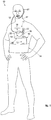
- Embodiments described here with reference to fig. 1 describe a safety apparatus for a diver, indicated as a whole with reference number 10.
- the safety apparatus 10 comprises a safety device 11 as described below, a gas cylinder of compressed gas 13 connected to the safety device 11 and a lifebelt 14 which can be worn by the diver and is connected to the gas cylinder 13.
- the gas cylinder 13 can contain air, oxygen, carbon dioxide, nitrogen or other gases or gas mixtures suitable to inflate the lifebelt 14.
- the gas cylinder 13 can be connected to the lifebelt 14 by means of a pipe 15.
- the lifebelt 14 can be a jacket, a band, a belt, a vest, a pneumatic rescue collar or suchlike, of a type known in the state of the art.
- the lifebelt 14 is configured so that, when inflated, it returns the diver to the surface and keeps him/her there, in particular with the face above the surface.
- the lifebelt 14 can be configured to keep the diver's face above the surface and facing in the opposite direction to the surface.
- the safety device 11 comprises a holding element 12 which can be held by the diver, an actuation element 18 and a tensioning mechanism 16 configured to drive the delivery of gas from the gas cylinder of compressed gas 13 to the lifebelt 14.
- connection element 17 can be a wire, a rope, a chain or similar or comparable elements.
- the safety device 11 can advantageously be positioned in proximity to the diver's mouth, so as to reduce the length of the connection element 17.
- the actuation element 18 and the tensioning mechanism 16 can be contained inside a casing 50.
- the casing 50 can be configured to prevent the components of the safety device 11 from coming into contact with the water.
- the casing 50 can be advantageously compact so as not to obstruct the diver, both above the surface and in the water.
- the casing 50 can advantageously have an ergonomic shape, so as not to hinder the correct movement of the diver.
- the holding element 12 is outside the casing 50, and the casing 50 comprises a first aperture 51 to allow the passage of the connection element 17.
- the casing 50 can be provided with a second aperture 52 to allow the connection of the gas cylinder of compressed gas 13.
- the gas cylinder of compressed gas 13 can be connected to the second aperture 52 of the casing 50 by means of a threaded connection.
- the safety device 11 can be located, during use, on the diver's chest, as shown by way of example only in fig. 1 .
- the safety device 11 can be located, during use, on the diver's back, for example in proximity to the nape or behind the diver's head.
- the safety device 11 can have a low weight, for example comprised between 200g and 500g.
- the safety device 11 can comprise a protective sheath 27 configured to at least partially cover the connection element 17 outside the casing 50 and prevent direct contact and a possible rubbing of the connection element 17 with the diver.
- the protective sheath 27 can be connected to the casing 50 in correspondence with the first aperture 51.
- the protective sheath 27 can be configured as a guide for the sliding of the connection element 17.
- the protective sheath 27 can be configured to support and direct the connection element 17.
- the protective sheath 27 can be made to pass behind the diver's ear in order to prevent a movement of the diver's head hindering the correct functioning of the safety device 11.
- the protective sheath 27 can be sufficiently rigid to allow the connection element 17 to exit from the diver's mouth in a substantially frontal direction, advantageously perpendicularly to the mouth.
- These embodiments allow the diver to hold the holding element 12 by exerting a traction force with a direction that is comfortable for the diver.
- the safety device 11 can comprise a gasket 28, for example an O-ring, so as to prevent water from entering inside the protective sheath 27 and/or the casing 50.
- a gasket 28 for example an O-ring, so as to prevent water from entering inside the protective sheath 27 and/or the casing 50.
- the gasket 28 can be located at one end of the protective sheath 27 opposite the first aperture 51.
- the tensioning mechanism 16 is configured to exert a traction force on the holding element 12 through the connection element 17.
- the holding element 12 is configured to be held, during use, inside the mouth of a diver.
- the holding element 12 can be located in the gap between the diver's teeth and lips and held by the muscles of the lips, for example by the orbicular muscle.
- the holding element 12 can be held by the diver with a traction force of 1.5N.
- the holding element 12 can be held in the gap between the diver's teeth and lips by a difference in pressure inside the diver's mouth.
- the holding element 12 can be advantageously conformed so as to adapt to the gap between diver's teeth and lips.
- the holding element 12 can have the shape of a button.
- the holding element 12 can have a thickness comprised between 1mm and 5mm.
- the holding element 12 can be held by the diver with his/her teeth.
- the holding element 12 can be bitten by the diver.
- the tensioning mechanism 16 is configured to drive the actuation element 18 when the holding action on the holding element 12 stops.
- the tensioning mechanism 16 can comprise a pulley 19, rotatable around an axis of rotation X and around which the connection element 17 is wound, a rack 20 associated with the pulley 19 and the actuation element 18, and a transmission system 21, for example one or more toothed wheels.
- the transmission system 21 is configured to transform the rotation of the pulley 19 around the axis of rotation X into a displacement of the rack 20 in a first direction Y, orthogonal to the axis of rotation X.
- the actuation element 18 can be associated with a spring 22.
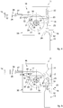
- a first operative condition shown in fig. 2
- the spring 22 is compressed in a second direction Z, orthogonal to the axis of rotation X and to the first direction Y.
- the spring 22 tends to relax and in this way exerts a thrust on the actuation element 18 in the second direction Z.
- the actuation element 18 can comprise a seating 23 for the insertion of one end of the rack 20.
- the seating 23 is provided with a surface inclined by an angle ⁇ (see fig. 2 ).
- the angle ⁇ can be comprised between 10° and 80° with respect to the first direction Y, advantageously between 15° and 75°.
- the end of the rack 20 is provided with a surface with an inclination corresponding to the angle ⁇ in order to be inserted inside the seating 23.
- the inclination of the seating 23 and of the end of the rack 20 allows to transmit the force exerted by the spring 22 to the rack 20 in the first direction Y.
- the rack 20 transmits the force to the pulley 19 by means of the transmission system 21, and the pulley 19 tends to rotate around the axis of rotation X in the first direction of rotation R1 indicated in fig. 3 .
- the holding of the holding element 12 by the diver prevents the connection element 17 from winding around the pulley 19 and, consequently, the rack 20 from moving away from the seating 23 ( fig. 2 ).
- the tensioning mechanism 16 can drive the actuation element 18 ( fig. 3 ).
- the actuation element 18 can therefore cooperate with the gas cylinder of compressed gas 13 and allow the delivery of gas through the pipe 15.
- the gas cylinder of compressed gas 13 can provide a button to deliver gas to the lifebelt 14, and the actuation element 18 is configured to cooperate with this button and activate the safety device 11.
- the gas cylinder 13 can comprise a membrane 24, and the actuation element 18 can comprise a perforation element 25 configured to perforate the membrane 24.
- the perforation element 25 can exert a force on the membrane 24 equal to or greater than 260 N.
- the actuation element 18 in the second operative condition can abut against the gas cylinder 13 - see fig. 3 - in order to prevent the gas contained in the gas cylinder of compressed gas 13 from entering inside the safety device 11.
- the lifebelt 14 Once inflated, the lifebelt 14 provides a buoyancy such as to bring the diver back to the surface and keep him/her there, even if the diver is wearing ballast equipment or weights.
- the pulley 19 can comprise a torsion spring 27 configured to oppose the rotation of the pulley 19.
- the transmission system 21 can comprise a first gear 28, associated with the pulley 19, and a second gear 29, associated with the rack 20.
- the second gear 29 can be provided with an obstacle element 30 configured to abut against another obstacle element 31 of the rack 20.
- the rack 20 can comprise a compression spring 32 able to oppose the movement of the rack 20 in the first direction Y.
- the safety device 11 can comprise a stop device 26, configured to hold the connection element 17.
- the stop device 26 can be positioned on the protective sheath 27, for example in the proximity of one end of the protective sheath 27.
- the diver can therefore release the holding element 12 without driving the safety device 11, allowing him/her, for example, to easily put on and/or remove the safety device 11.
- the diver can bring the safety device 11 back in operative condition by holding the holding element 12 inside his/her mouth and deactivating the stop device 26.
- the safety apparatus 10 can be reused following the activation of the safety device 11.
- the gas cylinder of compressed gas 13 can be disconnected from the safety device 11 in order to allow its replacement and/or resetting.
- the lifebelt 14 can be deflated and reset.
- the lifebelt 14 can be replaced.
- the actuation element 18 can be returned to the first operative condition using a reset tool 33, as shown by way of example only in figs. 6 and 7 .
- This reset tool 33 has a handle 34 and a rod 35 with a linear development.
- the rod 35 is provided with an abutment end 36 opposite the handle 34.
- the diver can insert the rod 35 of the reset tool 33 into the second aperture 52 of the casing 50 and push the abutment end 36 into contact with the actuation element 18 in the direction Z, so as to bring the actuation element 18 back into the first operative condition.
- the rod 35 can be hollow in order to allow the insertion of the perforation element 25 inside it, allowing a better grip of the reset tool 33.
- the diver can move the tensioning mechanism 16 by pulling the holding element 12 in the direction Y indicated in fig. 8 .
- the pulley 19 rotates in the second direction of rotation R2, opposite the first direction of rotation R1, and the rack 20 can be repositioned in the seating 23, resetting the safety device 11.
- the safety device 11 can comprise a containing body 37, selectively removable from the casing 50 of the safety device 11 in order to allow access to a compartment 38 in which the spring 22 is at least partially contained.
- the containing body 37 can be associated with the safety device 11 by means of a threaded connection 39.
- the containing body 37 comprises an abutment wall 40 against which the spring 22, in the first operative configuration, exerts a traction force.
- the safety device 11 functions substantially as described with reference to figs. 2 and 3 . It should be noted that the spring 22 is constrained to the actuation element 18 but is not constrained to the abutment wall 40 of the containing body 37.
- the gas cylinder of compressed gas 13 can be removed and the containing body 37 can be separated from the casing 50.
- the spring 22 can comprise a gripping portion 41 to facilitate the movement by the diver.
- the diver can therefore return the seating 23 of the actuation element 18 in correspondence with the rack 20.
- the diver can move the tensioning mechanism 16 by pulling the holding element 12 in the direction Y indicated in fig. 11 .
- the pulley 19 rotates in the second direction of rotation R2, opposite the first direction of rotation R1, and the rack 20 can be repositioned in the seating 23.
- the diver can again connect the gas cylinder of compressed gas 13 to the safety device 11 and compress the spring 22, repositioning the containing body 37 on the casing 50, so as to bring the safety device 11 back into the first operative condition as shown in fig. 9 .
- the diver can screw the containing body 37 with respect to the casing 50 in order to compress the spring 22.
- the safety device 11 comprises an electric motor 60 on which a toothed wheel 61 is keyed.
- the electric motor 60 can be powered by a battery 62.
- the battery 62 can be of the rechargeable type, or it can be disposed in a dedicated external compartment (not shown) of the casing 50, which can if necessary be opened by the user in order to carry out the replacement of the exhausted battery 62.
- the safety device 11 comprises a primary switch 63 associated with the casing 50 in a position easily accessible to the diver.
- Electric cables 64 are provided which electrically connect the electric motor 60, the battery 62, the primary switch 63 and the holding element 12 to form an electric circuit.
- the primary switch 63 is configured to selectively exclude the connection between the holding element 12 and the other actuation element, or electric motor 60, while the holding element 12 acts as a button to activate the circuit, as will be explained in greater detail below. In this way, the primary switch 63 can keep the safety device 11 deactivated, so that it is not accidentally activated, for example when the lifebelt is not in use or while it is being put on or removed by the diver.
- the electric cables 64 define as a whole a connection element between the holding element 12 and the electric motor 60, in a manner entirely similar to the element indicated with reference number 17 in the embodiments described above.
- the safety device 11 comprises a rack 20 which is engaged by the toothed wheel 61. Driving the electric motor 60 determines the rotation of the toothed wheel 61 and the consequent linear movement in the first direction Y1 (see the corresponding arrow in fig. 13 ).
- the safety device 11 comprises a first clamping member 65 and a second clamping member 66 mobile between a resting configuration ( fig. 13 ), in which they keep the actuation element 18 clamped, and a rotated configuration ( fig. 14 ) in which, instead, they allow the movement of the actuation element 18.
- the rotation of at least one of the clamping members, in particular of the second clamping member 66, is determined by the movement of the rack 20.
- Each clamping member is pivoted to the casing 50 in correspondence with a respective fulcrum 65A, 66A.
- the holding element 12 is held in the mouth of the diver who, by biting it, keeps it in a first condition I, shown in fig. 13 , in which the electric circuit is open and therefore the electric motor 60 is not powered.
- This first condition I is therefore an "off' condition in which the safety device 11 is not activated.
- the holding action by the diver stops and the diver no longer holds the holding element 12 in his/her mouth. Consequently, the holding element 12 moves into a second condition O, shown in fig. 14 , in which the electric circuit is closed and therefore the electric motor 60 is powered.
- This second condition O is therefore an "on" condition in which the safety device 11 is active.
- the electric motor 60 rotates the toothed wheel 61, for example in a clockwise direction as shown by the arrow F in fig. 14 , which determines the translation of the rack 20 in the direction Y1 (toward the right in the drawing).
- the rack 20 triggers the rotation of the second clamping member 66 around its fulcrum 66A, which causes the consequent un-clamping of the first clamping member 65, which was kept clamped by the second clamping member 66, as can easily be seen from the geometries of these members, visible in fig. 13 .
- the rotation of the first clamping member 65 causes a pin 23' of the actuation element 18, having a function equivalent to that of the seating 23, to no longer be kept clamped. Consequently, the actuation element 18 is driven in movement by the spring 22 so that the perforation element 25 perforates the membrane 24 so that the compressed gas contained in the gas cylinder 13 can flow out toward the lifebelt so as to inflate it.
- the safety apparatus 10 can be reused following the activation of the safety device 11, it being possible to bring it back from the condition shown in fig. 14 to that shown in fig. 13 in the manner described below.
- the pin 23' causes the first clamping member 65 to complete a rotation in the opposite direction to that previously described in order to also return to the position shown in fig. 13 .
- the user presses the main switch 63, which is also configured to reverse the direction of rotation of the electric motor 60, so as to activate a rotation of the electric motor 60 in the opposite direction to the arrow F indicated in fig. 3 , that is, in a counterclockwise direction.
- This opposite rotation determines the translation of the rack 20 in a direction opposite the previous one (that is, in the direction Y2, that is, toward the left with reference to the drawing), which causes the second clamping member 66 to return to the position of fig. 13 .
- a return spring 67 is provided which connects the second clamping member 66 to the casing 50, assisting the drive of the rack 20 in order to return this return member to the position shown in fig. 13 .
- the rack 20 can be constrained to the second clamping member 66.
- rack 20 and second clamping member 66 can be hinged to each other by means of a connection pin 68, as shown in fig. 13b .
- the safety device may not have the return spring 67.
Landscapes
- Engineering & Computer Science (AREA)
- Mechanical Engineering (AREA)
- Ocean & Marine Engineering (AREA)
- Emergency Lowering Means (AREA)
Priority Applications (1)
| Application Number | Priority Date | Filing Date | Title |
|---|---|---|---|
| EP19188102.8A EP3770058A1 (fr) | 2019-07-24 | 2019-07-24 | Dispositif de sécurité pour plongeur et appareil de sécurité comprenant ledit dispositif |
Applications Claiming Priority (1)
| Application Number | Priority Date | Filing Date | Title |
|---|---|---|---|
| EP19188102.8A EP3770058A1 (fr) | 2019-07-24 | 2019-07-24 | Dispositif de sécurité pour plongeur et appareil de sécurité comprenant ledit dispositif |
Publications (1)
| Publication Number | Publication Date |
|---|---|
| EP3770058A1 true EP3770058A1 (fr) | 2021-01-27 |
Family
ID=67438797
Family Applications (1)
| Application Number | Title | Priority Date | Filing Date |
|---|---|---|---|
| EP19188102.8A Withdrawn EP3770058A1 (fr) | 2019-07-24 | 2019-07-24 | Dispositif de sécurité pour plongeur et appareil de sécurité comprenant ledit dispositif |
Country Status (1)
| Country | Link |
|---|---|
| EP (1) | EP3770058A1 (fr) |
Citations (6)
| Publication number | Priority date | Publication date | Assignee | Title |
|---|---|---|---|---|
| US5921835A (en) * | 1995-02-15 | 1999-07-13 | Peter Cronin Gordon | Safety device |
| WO2000000384A1 (fr) | 1997-04-14 | 2000-01-06 | Hernandez Ricardo G | Systeme autosauveteur pouvant etre porte en permanence, pour plongeur en apnee |
| WO2007038794A2 (fr) | 2005-09-29 | 2007-04-05 | Oceanic Safety Systems Llc | Dispositif de securite pour la plongee libre |
| GR1006799B (el) | 2009-05-29 | 2010-06-11 | Πολυδωρος Βαϊδακης | Μηχανισμος αντιυποξιας |
| WO2013009170A1 (fr) * | 2011-05-10 | 2013-01-17 | Skoda Erik Wolfgang Rudolf | Ensemble de désaccouplement, ensemble support de ballast et ensemble de désaccouplement de ballast |
| CN108674609A (zh) * | 2018-05-16 | 2018-10-19 | 安徽工程大学 | 一种防溺水可调节救生圈 |
-
2019
- 2019-07-24 EP EP19188102.8A patent/EP3770058A1/fr not_active Withdrawn
Patent Citations (6)
| Publication number | Priority date | Publication date | Assignee | Title |
|---|---|---|---|---|
| US5921835A (en) * | 1995-02-15 | 1999-07-13 | Peter Cronin Gordon | Safety device |
| WO2000000384A1 (fr) | 1997-04-14 | 2000-01-06 | Hernandez Ricardo G | Systeme autosauveteur pouvant etre porte en permanence, pour plongeur en apnee |
| WO2007038794A2 (fr) | 2005-09-29 | 2007-04-05 | Oceanic Safety Systems Llc | Dispositif de securite pour la plongee libre |
| GR1006799B (el) | 2009-05-29 | 2010-06-11 | Πολυδωρος Βαϊδακης | Μηχανισμος αντιυποξιας |
| WO2013009170A1 (fr) * | 2011-05-10 | 2013-01-17 | Skoda Erik Wolfgang Rudolf | Ensemble de désaccouplement, ensemble support de ballast et ensemble de désaccouplement de ballast |
| CN108674609A (zh) * | 2018-05-16 | 2018-10-19 | 安徽工程大学 | 一种防溺水可调节救生圈 |
Similar Documents
| Publication | Publication Date | Title |
|---|---|---|
| US5485832A (en) | Face gear for diving and swimming | |
| EP1409081B1 (fr) | Masque reglable | |
| US20120274471A1 (en) | Methods and devices for rescuing a distressed diver | |
| WO2019028968A1 (fr) | Dispositif de propulsion assistée sous-marin, portable, équipé d'un dispositif de sauvetage ayant une fonction de direction auto-ajustable | |
| ATE381959T1 (de) | Kopfschutzgerät zum schnellen anziehen | |
| US20120128425A1 (en) | Method and device for automatic buoyancy compensation for a scuba diver or underwater device while in any orientation | |
| US20110290247A1 (en) | Methods and devices for rescuing a distressed diver | |
| AU693201B2 (en) | Life-saving aid | |
| JPWO2007099771A1 (ja) | ダイビング装備 | |
| US4079735A (en) | Emergency air breathing assembly for divers | |
| EP3390954B1 (fr) | Dispositif de contention humaine | |
| WO2017202182A1 (fr) | Appareil à corde de sauvetage et gilet de sauvetage, appareil de sauvetage aquatique | |
| US7654215B2 (en) | Diver propulsion system with separate battery and motor-transmission modules | |
| EP0921066B1 (fr) | Distributeur multiple de basse pression pour appareil respiratoire sous-marine | |
| US7124701B2 (en) | Propulsion system for scuba diver | |
| EP2826705A1 (fr) | Système de plongée autonome à alarme automatique | |
| WO2017034939A1 (fr) | Système récréatif immergé | |
| IT201800001897A1 (it) | Dispositivo di sicurezza per un subacqueo ed apparato di sicurezza comprendente detto dispositivo | |
| CA2966185C (fr) | Systeme integre de fourniture ombilicale de gaz, acquisition/documentation de donnees/communications, alimentation et securite d'accessoires pour des utilisateurs dans des environ nements hostiles | |
| US8951082B2 (en) | Device for increasing the buoyancy of a human body | |
| GB2164259A (en) | Shallow water breathing apparatus | |
| US2936755A (en) | Safety device for skin divers | |
| EP2707278A1 (fr) | Ensemble de désaccouplement, ensemble support de ballast et ensemble de désaccouplement de ballast | |
| RU2669182C1 (ru) | Устройство для плавания | |
| US6761603B1 (en) | Personal water rescue device |
Legal Events
| Date | Code | Title | Description |
|---|---|---|---|
| PUAI | Public reference made under article 153(3) epc to a published international application that has entered the european phase |
Free format text: ORIGINAL CODE: 0009012 |
|
| STAA | Information on the status of an ep patent application or granted ep patent |
Free format text: STATUS: THE APPLICATION HAS BEEN PUBLISHED |
|
| AK | Designated contracting states |
Kind code of ref document: A1 Designated state(s): AL AT BE BG CH CY CZ DE DK EE ES FI FR GB GR HR HU IE IS IT LI LT LU LV MC MK MT NL NO PL PT RO RS SE SI SK SM TR |
|
| AX | Request for extension of the european patent |
Extension state: BA ME |
|
| STAA | Information on the status of an ep patent application or granted ep patent |
Free format text: STATUS: REQUEST FOR EXAMINATION WAS MADE |
|
| 17P | Request for examination filed |
Effective date: 20210706 |
|
| RBV | Designated contracting states (corrected) |
Designated state(s): AL AT BE BG CH CY CZ DE DK EE ES FI FR GB GR HR HU IE IS IT LI LT LU LV MC MK MT NL NO PL PT RO RS SE SI SK SM TR |
|
| STAA | Information on the status of an ep patent application or granted ep patent |
Free format text: STATUS: THE APPLICATION IS DEEMED TO BE WITHDRAWN |
|
| 18D | Application deemed to be withdrawn |
Effective date: 20230201 |