EP3770065B1 - Anordnung aus rad und bremse eines luftfahrzeugs - Google Patents
Anordnung aus rad und bremse eines luftfahrzeugs Download PDFInfo
- Publication number
- EP3770065B1 EP3770065B1 EP20187005.2A EP20187005A EP3770065B1 EP 3770065 B1 EP3770065 B1 EP 3770065B1 EP 20187005 A EP20187005 A EP 20187005A EP 3770065 B1 EP3770065 B1 EP 3770065B1
- Authority
- EP
- European Patent Office
- Prior art keywords
- wheel
- brake
- brake assembly
- data concentrator
- assembly according
- Prior art date
- Legal status (The legal status is an assumption and is not a legal conclusion. Google has not performed a legal analysis and makes no representation as to the accuracy of the status listed.)
- Active
Links
Images




Classifications
-
- B—PERFORMING OPERATIONS; TRANSPORTING
- B64—AIRCRAFT; AVIATION; COSMONAUTICS
- B64C—AEROPLANES; HELICOPTERS
- B64C25/00—Alighting gear
- B64C25/32—Alighting gear characterised by elements which contact the ground or similar surface
- B64C25/42—Arrangement or adaptation of brakes
- B64C25/426—Braking devices providing an automatic sequence of braking
-
- B—PERFORMING OPERATIONS; TRANSPORTING
- B64—AIRCRAFT; AVIATION; COSMONAUTICS
- B64C—AEROPLANES; HELICOPTERS
- B64C25/00—Alighting gear
- B64C25/32—Alighting gear characterised by elements which contact the ground or similar surface
- B64C25/42—Arrangement or adaptation of brakes
-
- B—PERFORMING OPERATIONS; TRANSPORTING
- B60—VEHICLES IN GENERAL
- B60T—VEHICLE BRAKE CONTROL SYSTEMS OR PARTS THEREOF; BRAKE CONTROL SYSTEMS OR PARTS THEREOF, IN GENERAL; ARRANGEMENT OF BRAKING ELEMENTS ON VEHICLES IN GENERAL; PORTABLE DEVICES FOR PREVENTING UNWANTED MOVEMENT OF VEHICLES; VEHICLE MODIFICATIONS TO FACILITATE COOLING OF BRAKES
- B60T17/00—Component parts, details, or accessories of power brake systems not covered by groups B60T8/00, B60T13/00 or B60T15/00, or presenting other characteristic features
- B60T17/18—Safety devices; Monitoring
- B60T17/22—Devices for monitoring or checking brake systems; Signal devices
-
- B—PERFORMING OPERATIONS; TRANSPORTING
- B60—VEHICLES IN GENERAL
- B60T—VEHICLE BRAKE CONTROL SYSTEMS OR PARTS THEREOF; BRAKE CONTROL SYSTEMS OR PARTS THEREOF, IN GENERAL; ARRANGEMENT OF BRAKING ELEMENTS ON VEHICLES IN GENERAL; PORTABLE DEVICES FOR PREVENTING UNWANTED MOVEMENT OF VEHICLES; VEHICLE MODIFICATIONS TO FACILITATE COOLING OF BRAKES
- B60T8/00—Arrangements for adjusting wheel-braking force to meet varying vehicular or ground-surface conditions, e.g. limiting or varying distribution of braking force
- B60T8/17—Using electrical or electronic regulation means to control braking
- B60T8/1701—Braking or traction control means specially adapted for particular types of vehicles
- B60T8/1703—Braking or traction control means specially adapted for particular types of vehicles for aircrafts
-
- B—PERFORMING OPERATIONS; TRANSPORTING
- B64—AIRCRAFT; AVIATION; COSMONAUTICS
- B64C—AEROPLANES; HELICOPTERS
- B64C25/00—Alighting gear
- B64C25/32—Alighting gear characterised by elements which contact the ground or similar surface
- B64C25/34—Alighting gear characterised by elements which contact the ground or similar surface wheeled type, e.g. multi-wheeled bogies
-
- B—PERFORMING OPERATIONS; TRANSPORTING
- B64—AIRCRAFT; AVIATION; COSMONAUTICS
- B64C—AEROPLANES; HELICOPTERS
- B64C25/00—Alighting gear
- B64C25/32—Alighting gear characterised by elements which contact the ground or similar surface
- B64C25/34—Alighting gear characterised by elements which contact the ground or similar surface wheeled type, e.g. multi-wheeled bogies
- B64C25/36—Arrangements or adaptations of wheels, tyres or axles in general
-
- B—PERFORMING OPERATIONS; TRANSPORTING
- B64—AIRCRAFT; AVIATION; COSMONAUTICS
- B64F—GROUND OR AIRCRAFT-CARRIER-DECK INSTALLATIONS SPECIALLY ADAPTED FOR USE IN CONNECTION WITH AIRCRAFT; DESIGNING, MANUFACTURING, ASSEMBLING, CLEANING, MAINTAINING OR REPAIRING AIRCRAFT, NOT OTHERWISE PROVIDED FOR; HANDLING, TRANSPORTING, TESTING OR INSPECTING AIRCRAFT COMPONENTS, NOT OTHERWISE PROVIDED FOR
- B64F5/00—Designing, manufacturing, assembling, cleaning, maintaining or repairing aircraft, not otherwise provided for; Handling, transporting, testing or inspecting aircraft components, not otherwise provided for
- B64F5/60—Testing or inspecting aircraft components or systems
-
- B—PERFORMING OPERATIONS; TRANSPORTING
- B64—AIRCRAFT; AVIATION; COSMONAUTICS
- B64D—EQUIPMENT FOR FITTING IN OR TO AIRCRAFT; FLIGHT SUITS; PARACHUTES; ARRANGEMENT OR MOUNTING OF POWER PLANTS OR PROPULSION TRANSMISSIONS IN AIRCRAFT
- B64D45/00—Aircraft indicators or protectors not otherwise provided for
- B64D2045/0085—Devices for aircraft health monitoring, e.g. monitoring flutter or vibration
Definitions
- the invention relates to the field of aircraft wheel and brake assemblies.
- a braking system for the wheels of an aircraft comprises a plurality of brakes which each equip a so-called “braked” wheel of the aircraft.
- Each brake comprises one or more friction members, for example a stack of carbon discs, and one or more brake actuators which are mounted on an actuator support.
- the braking actuators are hydraulic actuators and the actuator support is a braking ring (also called a hydraulic ring).
- the braking actuators are electromechanical actuators and the actuator support is an actuator carrier.
- the braking system cooperates with a monitoring system which, for each wheel and brake assembly, measures and monitors certain parameters of the wheel and brake assembly.
- the monitoring system thus conventionally comprises, for each wheel and brake assembly, a temperature measuring device which measures a temperature of the stack of carbon discs, a speed measuring device which measures the speed of rotation of the wheel, and a pressure measuring device which measures the pressure prevailing in the tire of the wheel.
- the device for measuring the temperature of a wheel and brake assembly of the prior art conventionally comprises a type K thermocouple probe 1 positioned in a cavity of the torsion tube 2 of the brake 3.
- the thermocouple probe 1 is connected to a compensation box 4 which is located at the bottom of the undercarriage, or sometimes higher on the undercarriage.
- the junction between the copper wires and the chromel and "Alumel" (registered trademark) wires is made in the compensation box 4.
- the temperature of the cold junctions is measured in the compensation box 4 to perform temperature compensation .
- the speed measuring device conventionally uses a wheel cover 5 fixed to the rim 6 of the wheel 7 and rotating with the wheel 7 to drive a target thanks to a drive means 8.
- the speed of rotation of the wheel 7 is evaluated using a sensitive component.
- the target and the sensitive component are integrated into the axle 10 near one end of the axle 10.
- the tire pressure measuring device comprises a rotating part integral in rotation with the wheel 7 and a fixed part.
- the rotating part comprises a pressure sensor 11 which is mounted on the rim 6 and which comprises a sensitive cell placed in pneumatic communication with the inside of the tire of the wheel 7.
- the rotating part also comprises a cable 12 connected to the pressure sensor 11, and a rotating antenna.
- the fixed part comprises a fixed antenna and an electronic card. The pressure measurements are transmitted by the rotating part to the fixed part via the rotating antenna and the antenna fixed.
- the rotating part and the fixed part are integrated in the wheel cover 5 and in the axle 10.
- each undercarriage has one or more junction boxes 14 located at the bottom of the undercarriage or on the undercarriage.
- Each junction box 14 is connected to the measurement devices of one or more wheel and brake assemblies via electric wires 15.
- the junction box 14 is also connected to the rest of the aircraft by one or more strands of wires 16 which rises along the undercarriage towards the rest of the aircraft.
- the junction box(es) 14 and the strand(s) 16 make it possible to pool the transport of electrical power supplies and data between the aircraft and the measurement devices.
- the object of the invention is to reduce the cost and mass of a system for monitoring an aircraft wheel and brake assembly, to facilitate integration and maintenance, and to limit the risks of degradation of this system. monitoring.
- the data concentrator is mounted on the brake actuator support and acquires the measurement signals produced by the first measurement device and by the second measurement device.
- This configuration makes it possible to eliminate the numerous electric wires which circulate in the axle, as well as the junction box or boxes. The cost and weight of the surveillance system are therefore reduced, and its integration on the lander is facilitated.
- the invention makes it possible to avoid having to drill the axle for the passage of the electric wires, which makes it possible to simplify the manufacture of the undercarriage and therefore to reduce its cost.
- it is no longer necessary to disconnect the sensors mounted on the wheel or in the wheel cover to remove the wheel from the axle. Removing the wheel no longer requires manipulation of electrical connections, which facilitates maintenance operations and limits the risk of damage to this equipment.
- the first measuring device comprises a first target and a first sensitive component, the first target having a generally circular shape, being integral in rotation of a rim of the wheel, and being positioned close to a peripheral portion of the rim of the wheel, the first sensitive component being carried by the actuator support.
- the first measuring device comprises a first target and a first sensitive component, the first target having a generally circular shape and being mounted on a hub of the wheel, the first sensitive component being mounted on a torsion tube of the brake.
- thermocouple probe a thermocouple probe
- the third measuring device comprises a second target and a second sensitive component, the second target being connected to the friction, the second sensitive component being carried by the actuator support.
- the aircraft wheel and brake assembly firstly comprises a wheel 20 of an aircraft landing gear and a brake 21 intended to brake the wheel 20.
- the wheel 20 comprises a rim 22 which receives a tire and which is rotatably mounted on an axle 23 located at the bottom of the undercarriage.
- the brake 21 is here a hydraulic brake.
- the brake 21 comprises an actuator support, in this case a braking ring 24, which carries at least one braking actuator, in this case a plurality of braking actuators 25.
- the braking ring 24 is mounted on axle 23.
- the brake ring 24 comprises a plurality of casings 26 of generally cylindrical outer shape. Each casing 26 defines a cavity which opens on the side of the wheel 20 and which forms a piston housing.
- Each brake actuator 25 comprises a cylindrical sleeve 27 in which is mounted a piston 28 arranged to slide along an axis X.
- the sleeve 27 is received with sealing in the piston housing.
- a torsion tube 30 is fixed to the braking crown 24.
- the torsion tube 30 extends in the rim 22.
- the braking crown 24, and therefore the torsion tube 30 are stopped in rotation with respect to the axle 23 by stop means not shown here.
- the brake 21 also comprises at least one friction member, in this case a stack of carbon discs 31 composed of rotors which are integral in rotation with the rim 22 and of stators which are integral in rotation with the torque tube 30.
- the braking actuators 25 are arranged to selectively exert, during the admission of pressurized fluid, a braking force on the carbon discs 31.
- the aircraft wheel and brake assembly also comprises a first measuring device arranged to measure a speed of rotation of the wheel 20.
- the first measuring device comprises a first target 32 and a first sensitive component 33.
- the first target 32 has a generally circular shape and is here a metal toothed wheel.
- the first target 32 comprises alternating teeth (or sticks) and hollows.
- the teeth are either radial teeth, that is to say they extend at the level of a periphery of the first target 32 in radial directions, or axial teeth, that is to say they extend at a periphery of the first target 32 along axial directions.
- the first target 32 is integral in rotation with the rim 22 of the wheel 20.
- the first target 32 is positioned close to a peripheral portion of the rim 22 which is close to the rim flange 29, on the brake 21 side.
- first target 32 is either mounted directly on rim 22, or via any intermediate part itself fixed directly on rim 22, for example a heat shield or a part dedicated to fixing the first target 32.
- the first sensitive component 33 is here a magnetic sensor, in this case a Hall effect sensor 33.
- the Hall effect sensor 33 produces a first measurement signal, in this case an analog measurement signal whose amplitude depends on the presence of a tooth or a hollow in front of the Hall effect sensor 33.
- the first measurement signal has a frequency which is proportional to the speed of rotation of the target 32 and therefore to the speed of rotation of the wheel 20.
- the main purpose of the first measuring device is to detect a blockage of the wheel 20 or the beginning of a blockage.
- a braking computer of the braking system will modulate the braking command sent to brake 21 ( antiskid function) .
- first sensitive component 33 could be redundant to improve the availability of the antiskid function.
- the aircraft wheel and brake assembly also includes a second measuring device arranged to measure a temperature prevailing inside the stack of carbon discs 31.
- the second measuring device comprises a K-type thermocouple probe 34 positioned in a cavity of the torsion tube 30 of the brake 21.
- the wheel and brake assembly also includes a third measuring device arranged to measure wear of the carbon discs 31.
- the third measuring device comprises a second target and a second sensitive component 35.
- the second target is a rod, here metallic, which is connected to the stack of carbon discs 31.
- the second sensitive component 35 is a magnetic induction sensor, in this case an LVDT 35 (for Linear Variable Differential Transformer ).
- the LVDT 35 measures the displacement of the rod as the carbon discs 31 wear under the effect of friction during the braking of the aircraft.
- the wheel and brake assembly also includes a data concentrator 40.
- the data concentrator 40 includes a housing 41 and at least one electrical card 42 integrated into the housing 41.
- the data concentrator 40 is mounted on the brake ring 24.
- the data concentrator 40 is connected by electrical wires 46 to the Hall effect sensor 33 of the first measuring device, to the thermocouple probe 34 of the second measuring device, and to the LVDT 35 of the third measuring device. It is noted that the electric wires 46 which connect the data concentrator 40 to the thermocouple probe 34 are chromel and “Alumel” (registered trademark) wires.
- the data concentrator 40 comprises a single electrical connector 43.
- the data concentrator 40 is connected to a cable 44 via the electrical connector 43.
- the cable 44 incorporates electrical wires on which an electric power supply which makes it possible to supply the data concentrator 40 itself as well as the first, second and third measuring devices.
- the cable 44 also incorporates electric wires on which a communication bus is implemented.
- the data concentrator 40 acquires measurement signals produced by the first measurement device, the second measurement device and the third measurement device.
- the data concentrator 40 implements various processing operations on the measurement signals, and produces digital monitoring signals from the measurement signals.
- processing operations can comprise a digitization of the measurement signals, in which case the electrical card 42 of the data concentrator 40 comprises one or more analog-to-digital converters. This conversion is not mandatory, because the measurement signals produced by the sensors could already be digital signals.
- processing operations may also include formatting prior to transmission.
- These processing operations can also include an analysis of the measurement signals with the aim of carrying out, within the data concentrator 40 itself, a monitoring of the wheel and brake assembly.
- the digital monitoring signals may include alert messages.
- the processing carried out by the data concentrator 40 can be either relatively simple (and consist, for example, of a simple digitization of the measurement signals or else, if the measurement signals are already digital, of a simple transmission of said digital signals), or relatively complex.
- the data concentrator 40 transmits the digital monitoring signals, via the digital bus of the cable 44 (and therefore via the connector 43), outside the wheel and brake assembly, in this case towards the avionics systems of the aircraft.
- the information is then available for the braking computer ensuring the antiskid function, for the maintenance personnel, and can also be displayed in the cockpit for the pilots, in particular the temperature and the wear of the brakes.
- the data concentrator 40 can perfectly transmit the digital monitoring signals outside the data concentrator 40 via wireless communication.
- the connector 43 is in this case only used to electrically supply the data concentrator 40, or can be eliminated thanks to the use of a battery in the data concentrator 40.
- the data concentrator 40 then incorporates a wireless transmitter which transmits the digital surveillance signals to a receiver installed in the hold of the lander or at another place in the aircraft.
- the data concentrator 40 can also integrate a receiver without wire for data hub 40 to receive data.
- the wireless communication is for example a radioelectric communication, in which case the wireless transmitter and the wireless receiver comprise an antenna, or else an optical communication, in which case the wireless transmitter comprises a light source (for example a light-emitting diode ) and the wireless receiver includes a photoreceiver (eg, a photodiode).
- a light source for example a light-emitting diode
- the wireless receiver includes a photoreceiver (eg, a photodiode).
- the temperature compensation of the measurement signals produced by the thermocouple probe 34 of the second measurement device is carried out in the data concentrator 40.
- the junction between the copper wires and the chromel and "Alumel" (registered trademark) wires is made in the data concentrator 40.
- the temperature of the cold junctions is measured in the data concentrator 40.
- the temperature is measured by a temperature sensor, for example by an RTD probe (for Resistor Temperature Detector ) or by a thermistor.
- temperature compensation we therefore mean the joining of the wires and the measurement of the temperature of the cold junctions.
- the determination of the "compensated" temperature of the stack of disks 31 can also be carried out in the data concentrator 40.
- the data concentrator 40 comprises a processing component, mounted for example on the electrical card 42, which acquires the voltage measured at the terminals of the thermocouple probe 34, transforms the temperature of the cold junctions into a reference voltage, calculates a measured voltage compensated at from the measured voltage and the reference voltage, and deduces therefrom the temperature of the stack of disks 31.
- the processing component is for example a microcontroller.
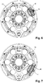
- the data concentrator 40 is positioned between two adjacent braking actuators 25 .
- the connector 43 extends towards the outside of the brake ring 24 in a radial direction, to be easily accessible. It could also extend outward from brake 21 in a direction parallel to the axis of rotation of wheel 20.
- the data concentrator 40 is located in a lower left zone of the brake ring 24.
- the data concentrator 40 is located in an upper left zone of the brake ring 24.
- the data concentrator 40 is located in an upper right zone of the brake ring 24.
- the concentrator data 40 is located in a lower right area of the brake ring 24.
- the data concentrator 40 To define the position of the data concentrator 40, it is sought in particular to protect the data concentrator 40 from the impact of gravel when the aircraft lands at high speed or else during the take-off phase.
- the best location for data concentrator 40 may vary from aircraft to aircraft.
- the location chosen may depend on the left side or right side position of the brake 21 on the undercarriage (and therefore on the left side or right side position of the wheel 20). Indeed, the part of the brake 21 most exposed to gravel is the part located forwards, which is not the same depending on whether the brake 21 is installed on the left side or the right side.
- the brake 21 can be equipped with two zones for fixing the data concentrator 40 (corresponding for example to the figure 4 and 7 ). The data concentrator 40 is then installed as on the figure 4 if the brake is mounted on the left side of the undercarriage, or as on the figure 7 if the brake is mounted on the right side of the undercarriage, so as not to be located towards the front of the undercarriage.
- the data concentrator 40 is fixed on the brake ring 24, between the brake actuator 25a and the brake actuator 25b which are adjacent brake actuators 25, as follows.
- the housing 41 of the data concentrator 40 comprises a plurality of first fixing means 50, in this case three first fixing means 50, which are located at regular angular intervals around the center of gravity of the data concentrator 40. This arrangement allows the data concentrator 40 and the bindings to support without damage the vibration levels generated by the brake 21 during braking, and the shocks undergone during landings.
- Each first fixing means 50 is here a fixing lug.
- the first fixing means 50 of the housing 40 cooperate with three second fixing means 51 of the brake ring 24.
- the three second fixing means 51 comprise a second fixing means 51a which extends from or on a rear portion 52a of the casing 26 of the piston housing of the braking actuator 25a, a second fixing means 51b which extends from or on a rear portion 52b of the casing 26 of the piston housing of the braking actuator 25b, and a second fixing means 51c positioned on the brake ring 24 between the two brake actuators 25a, 25b.
- rear portion of the casing of the piston housing is meant the part which extends not from the side of the wheel 20 (where the cavity which forms the piston housing opens) but from the other side.
- Each second fixing means 51 is here a boss.
- the first fixing means 50 are fixed to the second fixing means 51 by bolts.
- the housing 41 is fixed to the brake ring 24 via three fixing points comprising two fixing points located on the periphery of the braking ring 24, and a fixing point located between the two previous fixing points but close to the center of the brake crown 24.
- This configuration allows a particularly robust fixing.
- the data concentrator 40 does not protrude, or very little, beyond the thickness of the brake ring 24 since it is located between the envelopes 26 of the piston housings, its presence on the brake ring 24 does not constitute particularly inconvenient for maintenance operations.
- the first sensitive component 60 of the first measurement device that is to say here the Hall effect sensor 60 which produces a measurement signal representative of the speed rotation of the wheel
- the second sensitive component 62 of the third measuring device that is to say here the LVDT which produces a measurement signal representative of the wear of the disc stack, is integrated in or on the data concentrator 61.
- the data concentrator 61 becomes a single unit which includes the wheel speed sensor, the brake wear sensor and the conditioning of the brake temperature sensor. This solution is more compact and reduces the number of electrical wires on the brake.
- the first sensitive component 70 and the first target 71 of the first measuring device are installed at different locations.
- the first sensitive component 70 which is again a Hall effect sensor 70, is installed on the torsion tube 72 of the brake and, more particularly, inside the torsion tube 72, on a transverse annular web 73 of the tube twist 72.
- the first target 71 is itself again a toothed wheel and is mounted on the hub 74 of the wheel.
- the hub 74 could be manufactured in such a way as to present reliefs, for example an alternation of teeth and hollows, so that the hub 74 forms the first target 71.
- the third embodiment makes it possible to better control the clearance between the first sensitive component 70 and the first target 71 and the relative positions of the first sensitive component 70 and the first target 71.
- the mass of the first measuring device is reduced.
- the first measuring device is subjected to a higher temperature due to the proximity with the carbon discs of the brake.
- the first sensitive component and the first target may be different from those presented here.
- the sensitive component is a Hall effect sensor, and that the target is a toothed wheel. This configuration in no way limits the scope of the invention.
- the sensitive component can for example be a distance sensor or a detector.
- the detector supplies an “all or nothing” type measurement signal depending on whether the distance between the detector and the target is greater than or not greater than a predefined threshold.
- the distance sensor supplies a measurement signal which depends on the distance between the sensor and the target, as is the case for a proximity sensor for example.
- the measuring technology can for example be inductive technology, magnetic technology, ultrasonic technology or optical technology.
- Ultrasonic technology and optical technology allow the measurement to be carried out on non-metallic materials, which makes it possible to use targets made of lighter composite materials.
- the sensors, the targets and the technologies used may be different.
- the data concentrator housing could be fixed differently on the brake ring.
- the invention also applies to an electric brake: the actuator support is then an actuator carrier which carries one or more electromechanical brake actuators.
- the data concentrator could be connected to other measuring devices, for example a wheel tire pressure measuring device, a pressure measuring device in an undercarriage shock absorber, etc.
- the data concentrator could also be interrogated from the ground by an operator, thanks for example to an antenna integrated into the data concentrator.
Landscapes
- Engineering & Computer Science (AREA)
- Mechanical Engineering (AREA)
- Aviation & Aerospace Engineering (AREA)
- Transportation (AREA)
- Manufacturing & Machinery (AREA)
- Braking Arrangements (AREA)
- Regulating Braking Force (AREA)
Claims (15)
- Anordnung aus Rad und Bremse für ein Luftfahrzeug, umfassend:- ein Rad (20);- eine Bremse (21), die ausgebildet ist, um das Rad zu bremsen, und mindestens ein Reiborgan (31), einen Aktorträger (24) und mindestens einen Bremsaktor (25) umfasst, der von dem Aktorträger getragen wird und ausgebildet ist, um selektiv eine Bremskraft auf das Reiborgan auszuüben;- eine erste Messvorrichtung, die ausgebildet ist, um eine Drehgeschwindigkeit des Rades (20) zu messen;- eine zweite Messvorrichtung, die ausgebildet ist, um eine Temperatur des Reiborgans (31) zu messen;- einen Datenkonzentrator (40; 61), der ausgebildet ist, um Messsignale zu erfassen, die von der ersten Messvorrichtung und von der zweiten Messvorrichtung erzeugt werden, um die Messsignale derart zu verarbeiten, dass digitale Überwachungssignale erzeugt werden, und um die digitalen Überwachungssignale nach außerhalb der Anordnung aus Rad und Bremse für ein Luftfahrzeug zu übertragen,dadurch gekennzeichnet, dass der Datenkonzentrator (40; 61) ein Gehäuse (41) und mindestens eine in das Gehäuse (41) integrierte elektrische Karte (42) umfasst, wobei der Datenkonzentrator (40; 61) auf dem Aktorträger (24) angebracht ist.
- Anordnung aus Rad und Bremse für ein Luftfahrzeug nach Anspruch 1, bei der der Datenkonzentrator (40) zwischen zwei angrenzenden Bremsaktoren (25) positioniert ist, die von dem Aktorträger getragen werden.
- Anordnung aus Rad und Bremse für ein Luftfahrzeug nach Anspruch 2, bei der die Bremse (21) eine hydraulische Bremse ist, und bei der das Gehäuse (41) an Befestigungsmitteln (51) befestigt ist, die sich auf oder ab den hinteren Abschnitten zweier benachbarter Kolbengehäusemänteln (26) erstrecken.
- Anordnung aus Rad und Bremse für ein Luftfahrzeug nach einem der vorhergehenden Ansprüche, bei der der Datenkonzentrator (40) in einer unteren Zone des Aktorträgers (24) positioniert ist.
- Anordnung aus Rad und Bremse für ein Luftfahrzeug nach einem der vorhergehenden Ansprüche, bei der die erste Messvorrichtung ein erstes Ziel (32) und eine erste empfindliche Komponente (33; 60) umfasst, wobei das erste Ziel eine allgemeine kreisförmige Form hat, drehfest mit einer Felge (22) des Rades (20) verbunden und in der Nähe eines Umfangsabschnittes der Felge (22) des Rades (20) positioniert ist, wobei die erste empfindliche Komponente (33) von dem Aktorträger (24) getragen wird.
- Anordnung aus Rad und Bremse für ein Luftfahrzeug nach Anspruch 5, bei der die erste empfindliche Komponente (60) in den oder auf dem Datenkonzentrator (61) integriert ist.
- Anordnung aus Rad und Bremse für ein Luftfahrzeug nach einem der Ansprüche 1 bis 4, bei der die erste Messvorrichtung ein erstes Ziel (71) und eine erste empfindliche Komponente (70) umfasst, wobei das erste Ziel (71) eine allgemeine kreisförmige Form hat und an einer Nabe (74) des Rades anbracht ist, wobei die erste empfindliche Komponente (70) auf einem Torsionsrohr (72) der Bremse angebracht ist.
- Anordnung aus Rad und Bremse für ein Luftfahrzeug nach Anspruch 7, bei der die erste empfindliche Komponente (70) auf einer transversalen ringförmigen Scheibe (73) des Torsionsrohrs (72) angebracht ist.
- Anordnung aus Rad und Bremse für ein Luftfahrzeug nach Anspruch 7, bei der die Nabe (74) Reliefelemente umfasst und selbst das erste Ziel bildet.
- Anordnung aus Rad und Bremse für ein Luftfahrzeug nach einem der vorhergehenden Ansprüche, bei der die zweite Messvorrichtung eine Thermoelementsonde (34) umfasst und bei der ein Temperaturausgleich in dem Datenkonzentrator (40) erfolgt.
- Anordnung aus Rad und Bremse für ein Luftfahrzeug nach einem der vorhergehenden Ansprüche, ferner umfassend eine dritte Messvorrichtung, die ausgebildet ist, um eine Abnutzung des Reiborgans (31) zu messen.
- Anordnung aus Rad und Bremse für ein Luftfahrzeug nach Anspruch 11, bei der die dritte Messvorrichtung ein zweites Ziel und eine zweite empfindliche Komponente (35; 62) umfasst, wobei das zweite Ziel mit dem Reiborgan verbunden ist, wobei die zweite empfindliche Komponente von dem Aktorträger (24) getragen wird.
- Anordnung aus Rad und Bremse nach Anspruch 12, bei der die zweite empfindliche Komponente (61) in das oder auf dem Gehäuse des Datenkonzentrators (40) integriert ist.
- Anordnung aus Rad und Bremse eines Luftfahrzeugs nach einem der vorhergehenden Ansprüche, bei der der Datenkonzentrator (40) eine Antenne umfasst, um die digitalen Überwachungssignale über eine drahtlose Übertragung zu übertragen.
- Luftfahrzeugfahrwerk, umfassend eine Anordnung aus Rad und Bremse für ein Luftfahrzeug nach einem der vorhergehenden Ansprüche.
Applications Claiming Priority (1)
| Application Number | Priority Date | Filing Date | Title |
|---|---|---|---|
| FR1908422A FR3099133B1 (fr) | 2019-07-24 | 2019-07-24 | Ensemble de roue et frein d’aéronef |
Publications (2)
| Publication Number | Publication Date |
|---|---|
| EP3770065A1 EP3770065A1 (de) | 2021-01-27 |
| EP3770065B1 true EP3770065B1 (de) | 2022-06-22 |
Family
ID=68211072
Family Applications (1)
| Application Number | Title | Priority Date | Filing Date |
|---|---|---|---|
| EP20187005.2A Active EP3770065B1 (de) | 2019-07-24 | 2020-07-21 | Anordnung aus rad und bremse eines luftfahrzeugs |
Country Status (4)
| Country | Link |
|---|---|
| US (1) | US11873080B2 (de) |
| EP (1) | EP3770065B1 (de) |
| CN (1) | CN112278247B (de) |
| FR (1) | FR3099133B1 (de) |
Families Citing this family (8)
| Publication number | Priority date | Publication date | Assignee | Title |
|---|---|---|---|---|
| FR3099133B1 (fr) * | 2019-07-24 | 2021-08-06 | Safran Landing Systems | Ensemble de roue et frein d’aéronef |
| FR3115014B1 (fr) * | 2020-10-08 | 2024-04-26 | Safran Landing Systems | Architecture de freinage distribuée à sûreté améliorée |
| GB2613410A (en) * | 2021-11-30 | 2023-06-07 | Airbus Operations Ltd | Holder for component of temperature sensing system |
| GB2613414A (en) | 2021-11-30 | 2023-06-07 | Airbus Operations Ltd | Temperature sensing device for aircraft wheel brake |
| GB2617065A (en) * | 2022-03-25 | 2023-10-04 | Airbus Operations Ltd | Monitoring friction associated with a plurality of aircraft wheels |
| FR3147790A1 (fr) * | 2023-04-11 | 2024-10-18 | Safran Landing Systems | Atterrisseur à dispositif de mesure de vitesse de rotation |
| CN116729642B (zh) * | 2023-07-11 | 2025-08-26 | 中国工程物理研究院总体工程研究所 | 飞行器的模拟试验系统 |
| CN117465687B (zh) * | 2023-11-01 | 2026-04-14 | 沈阳飞机工业(集团)有限公司 | 飞机刹车系统高精度自动化检测方法 |
Citations (1)
| Publication number | Priority date | Publication date | Assignee | Title |
|---|---|---|---|---|
| EP1886887B1 (de) * | 2006-08-04 | 2013-11-20 | The Boeing Company | Systemarchitektur einer elektrischen Flugzeugbremssteuerung |
Family Cites Families (18)
| Publication number | Priority date | Publication date | Assignee | Title |
|---|---|---|---|---|
| FR2500798B1 (fr) * | 1981-01-28 | 1985-09-06 | Messier Hispano Sa | Dispositif de commande de freinage d'un aeronef |
| US6659233B2 (en) * | 2001-12-04 | 2003-12-09 | Hydro-Aire, Inc. | System and method for aircraft braking system usage monitoring |
| US7489996B2 (en) * | 2004-05-06 | 2009-02-10 | Hydro-Aire, Inc. | Antiskid control unit and data collection system for vehicle braking system |
| EP2213533B1 (de) * | 2009-01-28 | 2012-03-14 | Alenia Aeronautica S.p.A. | Bremssystem für das Fahrgestell eines Flugzeugs |
| GB2492202B (en) * | 2012-05-21 | 2013-12-11 | Messier Dowty Ltd | Aircraft brake assembly |
| FR2992288B1 (fr) * | 2012-06-25 | 2015-03-06 | Messier Bugatti Dowty | Procede de deblocage d'un frein de roue d'aeronef |
| US9950699B2 (en) * | 2013-09-26 | 2018-04-24 | The Boeing Company | Brake load alleviation functions |
| US9242739B2 (en) * | 2013-11-22 | 2016-01-26 | The Boeing Company | Methods to monitor components of an aircraft landing system |
| US9139293B2 (en) * | 2014-01-22 | 2015-09-22 | The Boeing Company | Optimized real-time antiskid control initialization for travel surfaces as a function of wheel spinup |
| US9428162B1 (en) * | 2015-05-19 | 2016-08-30 | Goodrich Corporation | System and method for brake control in response to load cell failure |
| ITUB20153709A1 (it) * | 2015-09-17 | 2017-03-17 | Itt Italia Srl | Dispositivo di analisi e gestione dei dati generati da un sistema frenante sensorizzato per veicoli |
| CN106081136B9 (zh) * | 2016-06-03 | 2018-03-09 | 北方工业大学 | 一种无人机滑跑侧偏检测方法与装置 |
| IT201600077944A1 (it) * | 2016-07-25 | 2018-01-25 | Itt Italia Srl | Dispositivo per il rilevamento della coppia residua di frenatura in un veicolo equipaggiato con freni a disco |
| FR3061139B1 (fr) * | 2016-12-23 | 2019-05-31 | Safran Landing Systems | Architecture de systeme de freinage pour aeronef |
| US10543909B2 (en) * | 2017-09-11 | 2020-01-28 | Goodrich Corporation | System and method for aircraft electric taxi brake optimization |
| FR3072924B1 (fr) * | 2017-10-30 | 2019-10-25 | Safran Landing Systems | Equipement electrique destine a etre relie a un actionneur electromecanique de freinage et a un actionneur electromecanique d'entrainement |
| US10941826B2 (en) * | 2018-09-12 | 2021-03-09 | Honeywell International Inc. | Determining estimated remaining use of brake assembly |
| FR3099133B1 (fr) * | 2019-07-24 | 2021-08-06 | Safran Landing Systems | Ensemble de roue et frein d’aéronef |
-
2019
- 2019-07-24 FR FR1908422A patent/FR3099133B1/fr active Active
-
2020
- 2020-07-21 EP EP20187005.2A patent/EP3770065B1/de active Active
- 2020-07-23 US US16/936,681 patent/US11873080B2/en active Active
- 2020-07-24 CN CN202010722526.6A patent/CN112278247B/zh active Active
Patent Citations (1)
| Publication number | Priority date | Publication date | Assignee | Title |
|---|---|---|---|---|
| EP1886887B1 (de) * | 2006-08-04 | 2013-11-20 | The Boeing Company | Systemarchitektur einer elektrischen Flugzeugbremssteuerung |
Also Published As
| Publication number | Publication date |
|---|---|
| EP3770065A1 (de) | 2021-01-27 |
| US20210024201A1 (en) | 2021-01-28 |
| US11873080B2 (en) | 2024-01-16 |
| CN112278247A (zh) | 2021-01-29 |
| CN112278247B (zh) | 2024-06-25 |
| FR3099133B1 (fr) | 2021-08-06 |
| FR3099133A1 (fr) | 2021-01-29 |
Similar Documents
| Publication | Publication Date | Title |
|---|---|---|
| FR3099133A1 (fr) | Ensemble de roue et frein d’aéronef | |
| EP2634447B1 (de) | Elektrische bremse für rad eines luftfahrzeugs, das mit einem elektromechanischen stellglied mit einem temperatursensor ausgestattet ist | |
| EP3000729B1 (de) | Fahrwerk eines luftfahrzeugs | |
| EP2893158B1 (de) | Turbinenmotor mit einer vorrichtung zum messen der geschwindigkeit und des drehmoments einer welle des turbinenmotors und verfahren zur überwachung der welle | |
| FR2875598A1 (fr) | Dispositif embarque de mesure de la masse et de la position du centre de gravite d'un aeronef | |
| CA2705552C (fr) | Architecture de systeme de freinage pour aeronef equipe de freins electromecaniques | |
| EP3002215B1 (de) | Fahrwerk eines luftfahrzeugs | |
| FR2986322A1 (fr) | Dispositif embarque de mesure de la masse et de la position du centre de gravite d'un aeronef | |
| EP3357811B1 (de) | Fahrwerk eines luftfahrzeugs | |
| FR2716002A1 (fr) | Couplemètre magnétique pour mesures absolues de torsion et de couple. | |
| EP2779372B1 (de) | Elektromechanisches Stellglied für Bremse | |
| EP3151016A2 (de) | Bestimmung der drehgeschwindigkeit oder- richtung eines körpers | |
| EP1153768B1 (de) | Radaufhängung an Achsbrücke oder Achse für Motorfahrzeuge | |
| FR2961871A1 (fr) | Roulement de roue de vehicule automobile comprenant un capteur d'efforts | |
| EP3751291B1 (de) | Anordnung aus rad und bremse eines luftfahrzeugs | |
| FR2993657A1 (fr) | Dispositif de mesure d'un couple transmis par un arbre de transmission de puissance avec prise en compte des variations de temperature | |
| FR3030382A1 (fr) | Moteur hydraulique couple | |
| EP0958984B1 (de) | Drehgestell für ein Schienenfahrzeug | |
| FR3134076A1 (fr) | Dispositif d’entraînement en rotation d’une roue d’aéronef | |
| FR3098762A1 (fr) | Système de vérification de la pression de gonflage de pneumatiques d’aéronef | |
| FR3147790A1 (fr) | Atterrisseur à dispositif de mesure de vitesse de rotation | |
| FR3079304A3 (fr) | Roue pour un vehicule | |
| WO2025253014A1 (fr) | Dispositif de freinage d'aeronef equipe d'un capteur de mesure du couple de freinage dudit dispositif | |
| FR3062722A1 (fr) | Cible de mesure magnetique | |
| FR3163133A1 (fr) | Dispositif de freinage d’aéronef équipé d’un capteur de mesure du couple de freinage dudit dispositif. |
Legal Events
| Date | Code | Title | Description |
|---|---|---|---|
| PUAI | Public reference made under article 153(3) epc to a published international application that has entered the european phase |
Free format text: ORIGINAL CODE: 0009012 |
|
| STAA | Information on the status of an ep patent application or granted ep patent |
Free format text: STATUS: THE APPLICATION HAS BEEN PUBLISHED |
|
| AK | Designated contracting states |
Kind code of ref document: A1 Designated state(s): AL AT BE BG CH CY CZ DE DK EE ES FI FR GB GR HR HU IE IS IT LI LT LU LV MC MK MT NL NO PL PT RO RS SE SI SK SM TR |
|
| AX | Request for extension of the european patent |
Extension state: BA ME |
|
| STAA | Information on the status of an ep patent application or granted ep patent |
Free format text: STATUS: REQUEST FOR EXAMINATION WAS MADE |
|
| 17P | Request for examination filed |
Effective date: 20210719 |
|
| RBV | Designated contracting states (corrected) |
Designated state(s): AL AT BE BG CH CY CZ DE DK EE ES FI FR GB GR HR HU IE IS IT LI LT LU LV MC MK MT NL NO PL PT RO RS SE SI SK SM TR |
|
| GRAJ | Information related to disapproval of communication of intention to grant by the applicant or resumption of examination proceedings by the epo deleted |
Free format text: ORIGINAL CODE: EPIDOSDIGR1 |
|
| STAA | Information on the status of an ep patent application or granted ep patent |
Free format text: STATUS: GRANT OF PATENT IS INTENDED |
|
| GRAP | Despatch of communication of intention to grant a patent |
Free format text: ORIGINAL CODE: EPIDOSNIGR1 |
|
| INTG | Intention to grant announced |
Effective date: 20220105 |
|
| GRAS | Grant fee paid |
Free format text: ORIGINAL CODE: EPIDOSNIGR3 |
|
| GRAA | (expected) grant |
Free format text: ORIGINAL CODE: 0009210 |
|
| STAA | Information on the status of an ep patent application or granted ep patent |
Free format text: STATUS: THE PATENT HAS BEEN GRANTED |
|
| AK | Designated contracting states |
Kind code of ref document: B1 Designated state(s): AL AT BE BG CH CY CZ DE DK EE ES FI FR GB GR HR HU IE IS IT LI LT LU LV MC MK MT NL NO PL PT RO RS SE SI SK SM TR |
|
| REG | Reference to a national code |
Ref country code: GB Ref legal event code: FG4D Free format text: NOT ENGLISH |
|
| REG | Reference to a national code |
Ref country code: CH Ref legal event code: EP |
|
| REG | Reference to a national code |
Ref country code: DE Ref legal event code: R096 Ref document number: 602020003637 Country of ref document: DE |
|
| REG | Reference to a national code |
Ref country code: AT Ref legal event code: REF Ref document number: 1499628 Country of ref document: AT Kind code of ref document: T Effective date: 20220715 |
|
| REG | Reference to a national code |
Ref country code: IE Ref legal event code: FG4D Free format text: LANGUAGE OF EP DOCUMENT: FRENCH |
|
| REG | Reference to a national code |
Ref country code: LT Ref legal event code: MG9D |
|
| REG | Reference to a national code |
Ref country code: NL Ref legal event code: MP Effective date: 20220622 |
|
| PG25 | Lapsed in a contracting state [announced via postgrant information from national office to epo] |
Ref country code: SE Free format text: LAPSE BECAUSE OF FAILURE TO SUBMIT A TRANSLATION OF THE DESCRIPTION OR TO PAY THE FEE WITHIN THE PRESCRIBED TIME-LIMIT Effective date: 20220622 Ref country code: NO Free format text: LAPSE BECAUSE OF FAILURE TO SUBMIT A TRANSLATION OF THE DESCRIPTION OR TO PAY THE FEE WITHIN THE PRESCRIBED TIME-LIMIT Effective date: 20220922 Ref country code: LT Free format text: LAPSE BECAUSE OF FAILURE TO SUBMIT A TRANSLATION OF THE DESCRIPTION OR TO PAY THE FEE WITHIN THE PRESCRIBED TIME-LIMIT Effective date: 20220622 Ref country code: HR Free format text: LAPSE BECAUSE OF FAILURE TO SUBMIT A TRANSLATION OF THE DESCRIPTION OR TO PAY THE FEE WITHIN THE PRESCRIBED TIME-LIMIT Effective date: 20220622 Ref country code: GR Free format text: LAPSE BECAUSE OF FAILURE TO SUBMIT A TRANSLATION OF THE DESCRIPTION OR TO PAY THE FEE WITHIN THE PRESCRIBED TIME-LIMIT Effective date: 20220923 Ref country code: FI Free format text: LAPSE BECAUSE OF FAILURE TO SUBMIT A TRANSLATION OF THE DESCRIPTION OR TO PAY THE FEE WITHIN THE PRESCRIBED TIME-LIMIT Effective date: 20220622 Ref country code: BG Free format text: LAPSE BECAUSE OF FAILURE TO SUBMIT A TRANSLATION OF THE DESCRIPTION OR TO PAY THE FEE WITHIN THE PRESCRIBED TIME-LIMIT Effective date: 20220922 |
|
| REG | Reference to a national code |
Ref country code: AT Ref legal event code: MK05 Ref document number: 1499628 Country of ref document: AT Kind code of ref document: T Effective date: 20220622 |
|
| PG25 | Lapsed in a contracting state [announced via postgrant information from national office to epo] |
Ref country code: RS Free format text: LAPSE BECAUSE OF FAILURE TO SUBMIT A TRANSLATION OF THE DESCRIPTION OR TO PAY THE FEE WITHIN THE PRESCRIBED TIME-LIMIT Effective date: 20220622 Ref country code: LV Free format text: LAPSE BECAUSE OF FAILURE TO SUBMIT A TRANSLATION OF THE DESCRIPTION OR TO PAY THE FEE WITHIN THE PRESCRIBED TIME-LIMIT Effective date: 20220622 |
|
| PG25 | Lapsed in a contracting state [announced via postgrant information from national office to epo] |
Ref country code: NL Free format text: LAPSE BECAUSE OF FAILURE TO SUBMIT A TRANSLATION OF THE DESCRIPTION OR TO PAY THE FEE WITHIN THE PRESCRIBED TIME-LIMIT Effective date: 20220622 |
|
| PG25 | Lapsed in a contracting state [announced via postgrant information from national office to epo] |
Ref country code: SM Free format text: LAPSE BECAUSE OF FAILURE TO SUBMIT A TRANSLATION OF THE DESCRIPTION OR TO PAY THE FEE WITHIN THE PRESCRIBED TIME-LIMIT Effective date: 20220622 Ref country code: SK Free format text: LAPSE BECAUSE OF FAILURE TO SUBMIT A TRANSLATION OF THE DESCRIPTION OR TO PAY THE FEE WITHIN THE PRESCRIBED TIME-LIMIT Effective date: 20220622 Ref country code: RO Free format text: LAPSE BECAUSE OF FAILURE TO SUBMIT A TRANSLATION OF THE DESCRIPTION OR TO PAY THE FEE WITHIN THE PRESCRIBED TIME-LIMIT Effective date: 20220622 Ref country code: PT Free format text: LAPSE BECAUSE OF FAILURE TO SUBMIT A TRANSLATION OF THE DESCRIPTION OR TO PAY THE FEE WITHIN THE PRESCRIBED TIME-LIMIT Effective date: 20221024 Ref country code: ES Free format text: LAPSE BECAUSE OF FAILURE TO SUBMIT A TRANSLATION OF THE DESCRIPTION OR TO PAY THE FEE WITHIN THE PRESCRIBED TIME-LIMIT Effective date: 20220622 Ref country code: EE Free format text: LAPSE BECAUSE OF FAILURE TO SUBMIT A TRANSLATION OF THE DESCRIPTION OR TO PAY THE FEE WITHIN THE PRESCRIBED TIME-LIMIT Effective date: 20220622 Ref country code: CZ Free format text: LAPSE BECAUSE OF FAILURE TO SUBMIT A TRANSLATION OF THE DESCRIPTION OR TO PAY THE FEE WITHIN THE PRESCRIBED TIME-LIMIT Effective date: 20220622 Ref country code: AT Free format text: LAPSE BECAUSE OF FAILURE TO SUBMIT A TRANSLATION OF THE DESCRIPTION OR TO PAY THE FEE WITHIN THE PRESCRIBED TIME-LIMIT Effective date: 20220622 |
|
| PG25 | Lapsed in a contracting state [announced via postgrant information from national office to epo] |
Ref country code: PL Free format text: LAPSE BECAUSE OF FAILURE TO SUBMIT A TRANSLATION OF THE DESCRIPTION OR TO PAY THE FEE WITHIN THE PRESCRIBED TIME-LIMIT Effective date: 20220622 Ref country code: IS Free format text: LAPSE BECAUSE OF FAILURE TO SUBMIT A TRANSLATION OF THE DESCRIPTION OR TO PAY THE FEE WITHIN THE PRESCRIBED TIME-LIMIT Effective date: 20221022 |
|
| REG | Reference to a national code |
Ref country code: DE Ref legal event code: R097 Ref document number: 602020003637 Country of ref document: DE |
|
| REG | Reference to a national code |
Ref country code: BE Ref legal event code: MM Effective date: 20220731 |
|
| PG25 | Lapsed in a contracting state [announced via postgrant information from national office to epo] |
Ref country code: MC Free format text: LAPSE BECAUSE OF FAILURE TO SUBMIT A TRANSLATION OF THE DESCRIPTION OR TO PAY THE FEE WITHIN THE PRESCRIBED TIME-LIMIT Effective date: 20220622 Ref country code: AL Free format text: LAPSE BECAUSE OF FAILURE TO SUBMIT A TRANSLATION OF THE DESCRIPTION OR TO PAY THE FEE WITHIN THE PRESCRIBED TIME-LIMIT Effective date: 20220622 |
|
| PG25 | Lapsed in a contracting state [announced via postgrant information from national office to epo] |
Ref country code: LU Free format text: LAPSE BECAUSE OF NON-PAYMENT OF DUE FEES Effective date: 20220721 Ref country code: DK Free format text: LAPSE BECAUSE OF FAILURE TO SUBMIT A TRANSLATION OF THE DESCRIPTION OR TO PAY THE FEE WITHIN THE PRESCRIBED TIME-LIMIT Effective date: 20220622 |
|
| PLBE | No opposition filed within time limit |
Free format text: ORIGINAL CODE: 0009261 |
|
| STAA | Information on the status of an ep patent application or granted ep patent |
Free format text: STATUS: NO OPPOSITION FILED WITHIN TIME LIMIT |
|
| 26N | No opposition filed |
Effective date: 20230323 |
|
| PG25 | Lapsed in a contracting state [announced via postgrant information from national office to epo] |
Ref country code: BE Free format text: LAPSE BECAUSE OF NON-PAYMENT OF DUE FEES Effective date: 20220731 |
|
| PG25 | Lapsed in a contracting state [announced via postgrant information from national office to epo] |
Ref country code: IE Free format text: LAPSE BECAUSE OF NON-PAYMENT OF DUE FEES Effective date: 20220721 |
|
| PG25 | Lapsed in a contracting state [announced via postgrant information from national office to epo] |
Ref country code: SI Free format text: LAPSE BECAUSE OF FAILURE TO SUBMIT A TRANSLATION OF THE DESCRIPTION OR TO PAY THE FEE WITHIN THE PRESCRIBED TIME-LIMIT Effective date: 20220622 |
|
| PG25 | Lapsed in a contracting state [announced via postgrant information from national office to epo] |
Ref country code: IT Free format text: LAPSE BECAUSE OF FAILURE TO SUBMIT A TRANSLATION OF THE DESCRIPTION OR TO PAY THE FEE WITHIN THE PRESCRIBED TIME-LIMIT Effective date: 20220622 |
|
| REG | Reference to a national code |
Ref country code: CH Ref legal event code: PL |
|
| PG25 | Lapsed in a contracting state [announced via postgrant information from national office to epo] |
Ref country code: MK Free format text: LAPSE BECAUSE OF FAILURE TO SUBMIT A TRANSLATION OF THE DESCRIPTION OR TO PAY THE FEE WITHIN THE PRESCRIBED TIME-LIMIT Effective date: 20220622 Ref country code: CY Free format text: LAPSE BECAUSE OF FAILURE TO SUBMIT A TRANSLATION OF THE DESCRIPTION OR TO PAY THE FEE WITHIN THE PRESCRIBED TIME-LIMIT Effective date: 20220622 Ref country code: CH Free format text: LAPSE BECAUSE OF NON-PAYMENT OF DUE FEES Effective date: 20230731 |
|
| PG25 | Lapsed in a contracting state [announced via postgrant information from national office to epo] |
Ref country code: HU Free format text: LAPSE BECAUSE OF FAILURE TO SUBMIT A TRANSLATION OF THE DESCRIPTION OR TO PAY THE FEE WITHIN THE PRESCRIBED TIME-LIMIT; INVALID AB INITIO Effective date: 20200721 |
|
| PG25 | Lapsed in a contracting state [announced via postgrant information from national office to epo] |
Ref country code: TR Free format text: LAPSE BECAUSE OF FAILURE TO SUBMIT A TRANSLATION OF THE DESCRIPTION OR TO PAY THE FEE WITHIN THE PRESCRIBED TIME-LIMIT Effective date: 20220622 |
|
| PG25 | Lapsed in a contracting state [announced via postgrant information from national office to epo] |
Ref country code: MT Free format text: LAPSE BECAUSE OF FAILURE TO SUBMIT A TRANSLATION OF THE DESCRIPTION OR TO PAY THE FEE WITHIN THE PRESCRIBED TIME-LIMIT Effective date: 20220622 |
|
| PG25 | Lapsed in a contracting state [announced via postgrant information from national office to epo] |
Ref country code: BG Free format text: LAPSE BECAUSE OF FAILURE TO SUBMIT A TRANSLATION OF THE DESCRIPTION OR TO PAY THE FEE WITHIN THE PRESCRIBED TIME-LIMIT Effective date: 20220622 |
|
| PG25 | Lapsed in a contracting state [announced via postgrant information from national office to epo] |
Ref country code: BG Free format text: LAPSE BECAUSE OF FAILURE TO SUBMIT A TRANSLATION OF THE DESCRIPTION OR TO PAY THE FEE WITHIN THE PRESCRIBED TIME-LIMIT Effective date: 20220622 |
|
| PGFP | Annual fee paid to national office [announced via postgrant information from national office to epo] |
Ref country code: DE Payment date: 20250722 Year of fee payment: 6 |
|
| PGFP | Annual fee paid to national office [announced via postgrant information from national office to epo] |
Ref country code: GB Payment date: 20250724 Year of fee payment: 6 |
|
| PGFP | Annual fee paid to national office [announced via postgrant information from national office to epo] |
Ref country code: FR Payment date: 20250722 Year of fee payment: 6 |