EP3770077A1 - Enveloppe pour cylindres de co2 - Google Patents
Enveloppe pour cylindres de co2 Download PDFInfo
- Publication number
- EP3770077A1 EP3770077A1 EP19187589.7A EP19187589A EP3770077A1 EP 3770077 A1 EP3770077 A1 EP 3770077A1 EP 19187589 A EP19187589 A EP 19187589A EP 3770077 A1 EP3770077 A1 EP 3770077A1
- Authority
- EP
- European Patent Office
- Prior art keywords
- cylinder
- shell
- cavity
- fixing
- cover
- Prior art date
- Legal status (The legal status is an assumption and is not a legal conclusion. Google has not performed a legal analysis and makes no representation as to the accuracy of the status listed.)
- Withdrawn
Links
- 238000003780 insertion Methods 0.000 claims abstract description 40
- 230000037431 insertion Effects 0.000 claims abstract description 40
- 238000000034 method Methods 0.000 claims abstract description 9
- 238000004064 recycling Methods 0.000 claims abstract description 6
- 239000004743 Polypropylene Substances 0.000 claims description 4
- -1 polypropylene Polymers 0.000 claims description 4
- 229920001155 polypropylene Polymers 0.000 claims description 4
- 239000004033 plastic Substances 0.000 claims description 3
- CURLTUGMZLYLDI-UHFFFAOYSA-N Carbon dioxide Chemical compound O=C=O CURLTUGMZLYLDI-UHFFFAOYSA-N 0.000 description 11
- XLYOFNOQVPJJNP-UHFFFAOYSA-N water Substances O XLYOFNOQVPJJNP-UHFFFAOYSA-N 0.000 description 7
- 229910002092 carbon dioxide Inorganic materials 0.000 description 5
- 239000001569 carbon dioxide Substances 0.000 description 5
- 238000007373 indentation Methods 0.000 description 5
- CDBYLPFSWZWCQE-UHFFFAOYSA-L Sodium Carbonate Chemical compound [Na+].[Na+].[O-]C([O-])=O CDBYLPFSWZWCQE-UHFFFAOYSA-L 0.000 description 4
- 239000011324 bead Substances 0.000 description 2
- 235000013361 beverage Nutrition 0.000 description 2
- 235000020188 drinking water Nutrition 0.000 description 2
- 239000003651 drinking water Substances 0.000 description 2
- 230000002349 favourable effect Effects 0.000 description 2
- 238000002347 injection Methods 0.000 description 2
- 239000007924 injection Substances 0.000 description 2
- 238000004519 manufacturing process Methods 0.000 description 2
- 230000001681 protective effect Effects 0.000 description 2
- XAGFODPZIPBFFR-UHFFFAOYSA-N aluminium Chemical compound [Al] XAGFODPZIPBFFR-UHFFFAOYSA-N 0.000 description 1
- 229910052782 aluminium Inorganic materials 0.000 description 1
- 239000002131 composite material Substances 0.000 description 1
- 238000001514 detection method Methods 0.000 description 1
- 230000007613 environmental effect Effects 0.000 description 1
- 238000004806 packaging method and process Methods 0.000 description 1
- 238000003909 pattern recognition Methods 0.000 description 1
- 239000008399 tap water Substances 0.000 description 1
- 235000020679 tap water Nutrition 0.000 description 1
- 239000002699 waste material Substances 0.000 description 1
Images



Classifications
-
- B—PERFORMING OPERATIONS; TRANSPORTING
- B65—CONVEYING; PACKING; STORING; HANDLING THIN OR FILAMENTARY MATERIAL
- B65D—CONTAINERS FOR STORAGE OR TRANSPORT OF ARTICLES OR MATERIALS, e.g. BAGS, BARRELS, BOTTLES, BOXES, CANS, CARTONS, CRATES, DRUMS, JARS, TANKS, HOPPERS, FORWARDING CONTAINERS; ACCESSORIES, CLOSURES, OR FITTINGS THEREFOR; PACKAGING ELEMENTS; PACKAGES
- B65D23/00—Details of bottles or jars not otherwise provided for
- B65D23/08—Coverings or external coatings
- B65D23/0885—Rigid shells for receiving the bottle or part of it
-
- B—PERFORMING OPERATIONS; TRANSPORTING
- B65—CONVEYING; PACKING; STORING; HANDLING THIN OR FILAMENTARY MATERIAL
- B65D—CONTAINERS FOR STORAGE OR TRANSPORT OF ARTICLES OR MATERIALS, e.g. BAGS, BARRELS, BOTTLES, BOXES, CANS, CARTONS, CRATES, DRUMS, JARS, TANKS, HOPPERS, FORWARDING CONTAINERS; ACCESSORIES, CLOSURES, OR FITTINGS THEREFOR; PACKAGING ELEMENTS; PACKAGES
- B65D23/00—Details of bottles or jars not otherwise provided for
- B65D23/08—Coverings or external coatings
- B65D23/0892—Net-like covers
-
- B—PERFORMING OPERATIONS; TRANSPORTING
- B65—CONVEYING; PACKING; STORING; HANDLING THIN OR FILAMENTARY MATERIAL
- B65D—CONTAINERS FOR STORAGE OR TRANSPORT OF ARTICLES OR MATERIALS, e.g. BAGS, BARRELS, BOTTLES, BOXES, CANS, CARTONS, CRATES, DRUMS, JARS, TANKS, HOPPERS, FORWARDING CONTAINERS; ACCESSORIES, CLOSURES, OR FITTINGS THEREFOR; PACKAGING ELEMENTS; PACKAGES
- B65D83/00—Containers or packages with special means for dispensing contents
- B65D83/14—Containers for dispensing liquid or semi-liquid contents by internal gaseous pressure, i.e. aerosol containers comprising propellant
- B65D83/16—Actuating means
- B65D83/20—Actuator caps
-
- B—PERFORMING OPERATIONS; TRANSPORTING
- B65—CONVEYING; PACKING; STORING; HANDLING THIN OR FILAMENTARY MATERIAL
- B65D—CONTAINERS FOR STORAGE OR TRANSPORT OF ARTICLES OR MATERIALS, e.g. BAGS, BARRELS, BOTTLES, BOXES, CANS, CARTONS, CRATES, DRUMS, JARS, TANKS, HOPPERS, FORWARDING CONTAINERS; ACCESSORIES, CLOSURES, OR FITTINGS THEREFOR; PACKAGING ELEMENTS; PACKAGES
- B65D85/00—Containers, packaging elements or packages, specially adapted for particular articles or materials
- B65D85/20—Containers, packaging elements or packages, specially adapted for particular articles or materials for incompressible or rigid rod-shaped or tubular articles
-
- B—PERFORMING OPERATIONS; TRANSPORTING
- B65—CONVEYING; PACKING; STORING; HANDLING THIN OR FILAMENTARY MATERIAL
- B65G—TRANSPORT OR STORAGE DEVICES, e.g. CONVEYORS FOR LOADING OR TIPPING, SHOP CONVEYOR SYSTEMS OR PNEUMATIC TUBE CONVEYORS
- B65G2201/00—Indexing codes relating to handling devices, e.g. conveyors, characterised by the type of product or load being conveyed or handled
- B65G2201/02—Articles
- B65G2201/0235—Containers
- B65G2201/0244—Bottles
-
- Y—GENERAL TAGGING OF NEW TECHNOLOGICAL DEVELOPMENTS; GENERAL TAGGING OF CROSS-SECTIONAL TECHNOLOGIES SPANNING OVER SEVERAL SECTIONS OF THE IPC; TECHNICAL SUBJECTS COVERED BY FORMER USPC CROSS-REFERENCE ART COLLECTIONS [XRACs] AND DIGESTS
- Y02—TECHNOLOGIES OR APPLICATIONS FOR MITIGATION OR ADAPTATION AGAINST CLIMATE CHANGE
- Y02W—CLIMATE CHANGE MITIGATION TECHNOLOGIES RELATED TO WASTEWATER TREATMENT OR WASTE MANAGEMENT
- Y02W30/00—Technologies for solid waste management
- Y02W30/50—Reuse, recycling or recovery technologies
- Y02W30/80—Packaging reuse or recycling, e.g. of multilayer packaging
Definitions
- the invention relates to a casing for CO 2 cylinders, a device with a CO 2 cylinder, and a method for recycling a CO 2 cylinder.
- CO 2 cylinders are gas cartridges that are filled with carbon dioxide (CO 2 ).
- CO 2 cylinders are used in drinking water bubblers to add CO 2 to tap water in order to produce carbonated table water (soda water).
- the water is filled into pressure-resistant bottles and screwed pressure-tight to a holder of the drinking water bubbler.
- the carbon dioxide is introduced into the water via a pipe and valve system, whereby carbon dioxide (H 2 CO 3 ) is formed by reaction of the carbon dioxide (CO 2 ) with water (H 2 O).
- the carbonic acid content in the soda water produced is determined by the duration of the introduction of the carbon dioxide.
- CO 2 cylinders filled with around 300-500 g CO 2 can produce up to 100 liters of soda water. After a CO 2 cylinder has been emptied, it is removed from the soda maker and then disposed of or exchanged for a filled CO 2 cylinder at certain retailers, such as supermarkets. For reasons of environmental protection and the reduction of waste, it is preferable to recycle the CO 2 cylinders by taking the empty cylinders to a dealer and then refilling them, rather than disposing of the CO 2 cylinders.
- dealers such as supermarkets do not generally allow a return, but only an exchange of empty for filled CO 2 cylinders.
- Another disadvantage is that for this exchange it is necessary to contact an employee in order to deliver the empty CO 2 cylinder and to receive a filled CO 2 cylinder.
- the empty CO 2 cylinders are returned unpacked and without a protective cover, so that damage to the CO 2 cylinders is possible when they are returned and during further handling by the dealer’s employee.
- the DE 1858289 U discloses a carrier pack for bottles with bead ribs being provided on the outside.
- the bead ribs serve as buffer elements and thus as a kind of break protection.
- the carrying pack consists of pieces of film and can optionally also be designed for just a single bottle.
- Another protective cover for bottles is in the DE 6753487 U shown.
- the casing disclosed has ribs which are brought into connection with further casings, whereby a composite of casings is produced.
- the object of the present invention is to alleviate or remedy at least individual disadvantages of the known methods for returning or recycling CO 2 cylinders.
- the invention aims to improve the process of returning or recycling CO 2 cylinders.
- the invention provides a cover for CO 2 cylinders, comprising a shell, the shell forming a cavity for receiving a CO 2 cylinder, the cover being able to be picked up by an empties machine for taking back returnable bottles.
- the invention also provides a device with a CO 2 cylinder and a cover for CO 2 cylinders, the cover having a shell and being able to be picked up by an empties machine for taking back returnable bottles, the shell having a cavity for holding a CO 2 cylinder forms, the CO 2 cylinder being received in the shell.
- the shell of the casing according to the invention at least partially delimits the cavity so that a CO 2 cylinder can be received and the cavity can be open.
- the CO 2 cylinder can partially protrude from the cavity so that the CO 2 cylinder is at least partially arranged in the cavity. Because the cover is designed in such a way that it can be picked up by an empties machine to take back returnable bottles, the existing system of returning returnable bottles can be used to recycle CO 2 cylinders.
- Empty vending machines are used to take back empty beverage packaging that is subject to a deposit, such as returnable bottles or beverage cans. The empties are scanned, weighed and automatically checked for returnability using pattern recognition.
- the casing according to the invention in which a CO 2 cylinder is accommodated, can also be automatically detected and picked up by the empties machine.
- a manual recording and receipt of the empty CO 2 cylinder by an employee of the dealer is not necessary.
- Another advantage is that the CO 2 cylinder is better protected from mechanical damage by the inclusion of the CO 2 cylinder in the cavity of the shell.
- the CO 2 cylinder is inserted into the insertion opening of the casing and at least partially received in the cavity of the shell of the casing connected to the insertion opening.
- the CO 2 cylinder is at least partially arranged in the cavity and is fixed in it.
- the envelope with the CO 2 cylinder accommodated in the cavity is picked up by an empties machine for the return of returnable bottles.
- the automatic empties machine is programmed in such a way that it recognizes casings according to the invention with CO 2 cylinders that have been received and that they receive them.
- the casing has a fixing device for fixing a CO 2 cylinder accommodated in the cavity of the shell.
- the CO 2 cylinder can be positioned in the shell and the CO 2 cylinder can be prevented from falling out of the shell.
- mechanical damage to the CO 2 cylinder can be further reduced.
- the fixing device has at least one fixing hook, preferably at least two fixing hooks, particularly preferably exactly two fixing hooks, for fixing a CO 2 cylinder received in the cavity. This enables the fixing device to be manufactured in a simple and inexpensive manner.
- the casing has an insertion opening connected to the cavity of the shell for introducing a CO 2 cylinder into the cavity.
- the CO 2 cylinder can simply be inserted into the cavity via the insertion opening.
- the CO 2 cylinder can advantageously be removed again from the cavity via the insertion opening in order to separate the CO 2 cylinder from the casing.
- the fixing device in particular the at least one fixing hook, is arranged on the insertion opening.
- the CO 2 cylinder can be fixed to the introduction opening in order to prevent the CO 2 cylinder from falling out of the cavity via the introduction opening.
- the fixing device in particular the at least one fixing hook
- the fixing device is elastically deformable from a first position to a second position.
- the fixing device in particular the at least one fixing hook
- the fixing device in particular the at least one fixing hook, particularly preferably returns to the first position when the CO 2 cylinder is received in the cavity in order to better fix the CO 2 cylinder.
- the shell has at least one guide rail for guiding a CO 2 cylinder in the cavity in a first direction. This makes it easier to introduce the CO 2 cylinder into the shell and the CO 2 cylinder can be positioned exactly in the cavity of the shell.
- the casing has an outlet opening connected to the cavity of the shell for the cylinder head of the CO 2 cylinder to exit from the cavity.
- the outlet opening is preferably arranged on a side of the shell opposite the inlet opening so that when the CO 2 cylinder is inserted into the inlet opening and when it is received in the cavity, the CO 2 cylinder with the cylinder head emerges from the outlet opening and is fixed in the cavity can.
- the shell has a first part shell and a second part shell, the first and second part shells being connected to one another, preferably being releasably connected to one another.
- the first and the second partial shell can be manufactured separately and then the shell can be manufactured by connecting the first to the second partial shell.
- the first and second partial shells are particularly preferably injection molded parts made of plastic.
- first partial shell has at least one locking hook and the second partial shell has at least one corresponding receiving opening for receiving the at least one locking hook of the first partial shell for connecting the first to the second partial shell.
- first partial shell can easily be detachably connected to the second partial shell.
- the second part-shell has at least one further locking hook and the first part-shell has at least one further corresponding receiving opening for receiving the at least one further locking hook of the first part-shell for connecting the first to the second part-shell.
- first and second partial shells are identical.
- the first and second partial shells can be manufactured more cost-effectively using the same machine without retooling.
- the shell has essentially the outer shape of a returnable bottle.
- the cover can be picked up particularly easily by an empties machine for taking back returnable bottles.
- the sheath consists of a plastic, preferably of polypropylene.
- the cavity of the shell is for receiving a CO 2 cylinder with a capacity of 425 g CO 2 .
- the envelope can be used to hold commercially available CO 2 cylinders.
- the fixing device in particular a fixing hook
- the fixing device is elastically deformed by the introduction of the CO 2 cylinder into the insertion opening from a first position to a second position, and when the CO 2 cylinder is received in the cavity, the fixing device, especially the fixing hook, returns to the first position for fixing the CO 2 cylinder. This enables the CO 2 cylinder to be easily fixed in the cavity of the shell.
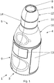
- Fig. 1 shows a cover 1 according to the invention for CO 2 cylinders 2 (see Figure 3-5 ), which has a shell 3.
- the sheath 1 consists of polypropylene.
- the shell 3 has a first partial shell 4 and a second partial shell 5, which are detachably connected to one another, the shell 3 having the outer shape of a returnable bottle, so that the cover 1 can be picked up by an empties machine for taking back returnable bottles.
- the shell 3 forms a cavity 6 in which a CO 2 cylinder 2 can be accommodated.
- the casing 1 has an essentially circular insertion opening 7 (see FIG Fig.
- the casing On an opposite side of the tray 3 on the bottle head of the essentially reusable bottle-shaped tray 3, the casing has a circular outlet opening 8 which is arranged parallel to the insertion opening 7. Adjacent to the insertion opening 7, the shell 3 has an essentially cylindrical section 9, which is adjoined by an essentially conically converging section 10. This essentially conically converging section 10 is adjoined in the direction of the outlet opening 8 by a further essentially cylindrical section 11 and another essentially conically converging section 12, which form the bottle neck or the bottle head of the essentially returnable bottle-shaped tray 3.
- the axes of rotation of the insertion opening 7, the essentially cylindrical section 9, the essentially conically converging section 10, the further essentially cylindrical section 11, the further essentially conically converging section 12 and the outlet opening 8 are identical.
- the shell 3 On the outer surface of the essentially cylindrical section 9, the shell 3 has four inscription surfaces 13, which have a smoother surface than the rest of the surface of the shell 3.
- stickers can be attached to the inscription surfaces 13, which, for example, show the logo of the marketer of the cover 1.
- the shell 3 has a further ring-shaped inscription surface 14 with a likewise smoother surface than the remaining surface of the shell 3, in order to attach stickers.
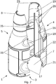
- Fig. 2 shows the shell 1 according to Fig. 1 , wherein the first partial shell 4 is detached from the second partial shell 5.
- the first 4 and second 5 part shells are identical injection molded parts made of polypropylene.
- the connecting surface between the first 4 and the second 5 sub-shells runs vertically through the essentially reusable bottle-shaped tray 3 and perpendicular to the insertion opening 7 and to the outlet opening 8.
- the first 4 and second 5 sub-shells each point at the vertical connecting surface for connecting to the each other partial shell two directly Locking hooks 15 arranged one above the other and two corresponding receiving openings 16 arranged directly one above the other for receiving the locking hooks 15.
- a locking hook 15 and a receiving opening 16 are arranged in the same horizontal plane parallel to the insertion opening 7 on the vertical connecting surface at a distance from one another, this distance being the outer diameter of a commercially available CO 2 cylinder made of aluminum with a capacity of 425 g CO 2 corresponds.
- the locking hooks 15 and the receiving openings 16 are arranged in bowl-shaped indentations 17 on the essentially cylindrical section 9 and in further bowl-shaped indentations 18 on the essentially conically converging section 10.
- a respective receiving opening 16 releasably receives a locking hook 15, so that two connections of a locking hook 15 with a receiving opening 16 are arranged at two different distances from the insertion opening 7.
- a guide rail 19 is arranged in each case parallel to the vertical connecting surface and perpendicular to the insertion opening 7, each of which comprises two parallel rail bodies 20.
- the distance between the guide rail 19 of the first partial shell 4 and the guide rail 19 of the second partial shell 5 also corresponds to the outer diameter of a commercially available CO 2 cylinder with a capacity of 425 g CO 2 .
- a commercially available CO 2 cylinder can be arranged in the cavity 8 of the shell 3 in such a way that it is supported by the locking hooks 15, the receiving openings 16 and the guide rails 19 limited and is not displaceable in a horizontal direction parallel to the insertion opening 7.
- the first 4 and second 5 partial shells each have two connecting devices 21 in the vertical connecting plane, which are connected to the two connecting devices of the respective other partial shell are releasably connected. Also on the lower side of the shell facing the insertion opening 7, the first 4 and second 5 partial shells each have a fixing hook 22 which is arranged in the plane of the insertion opening 7 and protrudes into the insertion opening 7.
- the two fixing hooks 22 are elastically deformable and are arranged on the first 4 and second 5 partial shells in such a way that, in the connected state of the two partial shells, the fixing hooks 22 are arranged on two opposite sides of the essentially circular insertion opening 7, whereby the fixing hook 22 protrudes into it in the insertion opening 7, the distance between the two fixing hooks 22 is less than the diameter of the insertion opening 7.
- the first 4 and second 5 partial shells have a bulge 23 delimiting the outlet opening 8 in the connected state of the two partial shells.
- the bulges 23 form a ring with an inner diameter which corresponds to the outer diameter of a cylinder head of a commercially available CO 2 cylinder.
- Fig. 3 and 4th show the shell 1 according to Fig. 1 when inserting a CO 2 cylinder 2 into the insertion opening 7.
- the CO 2 cylinder 2 is guided with the cylinder head 24 of the CO 2 cylinder 2 first into the insertion opening 7 of the shell 1 and, with the aid of the guide rails 19, into the cavity 6 of the shell 3 guided in a first direction 25.
- the first direction 25 is parallel to the rail bodies 20 of the guide rails 19 and perpendicular to the insertion opening 7.
- the cylinder body 26 When the CO 2 cylinder 2 is further inserted, the cylinder body 26 reaches the insertion opening 7 after the cylinder head 24, and when the cylinder body 26 is inserted into the insertion opening 7, the two elastically deformable fixing hooks 22 protruding into the insertion opening 7 are deformed by the cylinder body 26 in the first direction 25 from a first position to a second position.
- the fixing hooks 22 in the second position on the cylinder body 26 until the CO 2 cylinder 2 has been completely inserted into the insertion opening 7 and received in the cavity 6 of the shell 3.
- Fig. 6 shows a detail of the shell 1 with the CO 2 cylinder 2 accommodated therein according to FIG Fig. 5 in the area of the insertion opening 7.
- the CO 2 cylinder 2 rests with a bottom surface 27 opposite the cylinder head 24 on an L-shaped tab of the two fixing hooks 22. Because the fixing hooks 22 can only be elastically deformed with considerable force in a second direction 28 opposite the first direction 25, the fixing hooks 22 prevent the CO 2 cylinder 2 from slipping out of the cavity 6 of the shell 3.
- the fixing hooks 22 are deformed from a first position to a second position with the aid of a tool provided for this purpose or by hand in order to close the CO 2 cylinder 2 from the fixing hooks 22 to solve.
- the CO 2 cylinder 2 can then be moved out of the cavity 6 in the second direction 28 via the insertion opening 7. After the CO 2 cylinder 2 has left the cavity 6, the fixing hooks 22 return from the second to the first position, so that a CO 2 cylinder can again be accommodated in the casing 1.
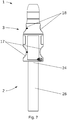
- Fig. 7 and 8th show the shell 1 and the CO 2 cylinder 2 according to FIG Fig. 4 or. Fig. 5 .
- the shell-shaped indentations 17 and the further shell-shaped indentations 18 together with the locking hooks 15 and receiving openings 16 arranged on these indentations serve to delimit the cavity 6 of the shell 3 in order to position the CO 2 cylinder 2 accommodated in the cavity 6.
- the height of the envelope 1 is less than the height of the CO 2 cylinder 2, so that when the CO 2 cylinder 2 is fixed in the cavity 6 of the envelope 1, the CO 2 cylinder 2 protrudes from the outlet opening 8.
- the height of the shell 1 is selected such that the CO 2 cylinder 2 in the cavity 6 between the guide rails 19, the locking hooks 15 and the receiving openings 16 on the one hand and the Curvature 23 and the fixing hook 22 on the other hand is fixed.
- the CO 2 cylinder 2 arranged in this way in the cover 1 can be picked up together with the cover 1 due to the shape of the cover 1 by an empties machine for taking back returnable bottles. Because the cylinder head 24 protrudes from the envelope 1, an empties machine can detect whether a CO 2 cylinder 2 is arranged in the envelope 1, thus avoiding the improper return of empty envelopes or envelopes 1 filled with other objects.
Landscapes
- Engineering & Computer Science (AREA)
- Mechanical Engineering (AREA)
- Chemical & Material Sciences (AREA)
- Dispersion Chemistry (AREA)
- Closures For Containers (AREA)
- Details Of Rigid Or Semi-Rigid Containers (AREA)
- Packages (AREA)
- Control Of Vending Devices And Auxiliary Devices For Vending Devices (AREA)
- Refuse Receptacles (AREA)
- Filling Or Discharging Of Gas Storage Vessels (AREA)
Priority Applications (11)
| Application Number | Priority Date | Filing Date | Title |
|---|---|---|---|
| EP19187589.7A EP3770077A1 (fr) | 2019-07-22 | 2019-07-22 | Enveloppe pour cylindres de co2 |
| EP20746582.4A EP4003857A1 (fr) | 2019-07-22 | 2020-07-20 | Enveloppe pour cylindre co² |
| KR1020227005657A KR20220041127A (ko) | 2019-07-22 | 2020-07-20 | Co2 실린더용 커버 |
| PCT/EP2020/070475 WO2021013807A1 (fr) | 2019-07-22 | 2020-07-20 | Enveloppe pour cylindre co2 |
| CN202080053086.8A CN114341010A (zh) | 2019-07-22 | 2020-07-20 | 用于co2气瓶的外罩 |
| JP2021576837A JP2022542000A (ja) | 2019-07-22 | 2020-07-20 | Co2シリンダに用いるためのカバー |
| US17/627,837 US20220258920A1 (en) | 2019-07-22 | 2020-07-20 | Cover for C02 cylinders |
| CA3160616A CA3160616A1 (fr) | 2019-07-22 | 2020-07-20 | Enveloppe pour cylindre co2 |
| BR112022001197A BR112022001197A2 (pt) | 2019-07-22 | 2020-07-20 | Invólucro para cilindros de co2 |
| AU2020317637A AU2020317637A1 (en) | 2019-07-22 | 2020-07-20 | Cover for CO2 cylinders |
| IL289027A IL289027A (en) | 2019-07-22 | 2021-12-15 | Cover for co2 cylinders |
Applications Claiming Priority (1)
| Application Number | Priority Date | Filing Date | Title |
|---|---|---|---|
| EP19187589.7A EP3770077A1 (fr) | 2019-07-22 | 2019-07-22 | Enveloppe pour cylindres de co2 |
Publications (1)
| Publication Number | Publication Date |
|---|---|
| EP3770077A1 true EP3770077A1 (fr) | 2021-01-27 |
Family
ID=67438455
Family Applications (2)
| Application Number | Title | Priority Date | Filing Date |
|---|---|---|---|
| EP19187589.7A Withdrawn EP3770077A1 (fr) | 2019-07-22 | 2019-07-22 | Enveloppe pour cylindres de co2 |
| EP20746582.4A Withdrawn EP4003857A1 (fr) | 2019-07-22 | 2020-07-20 | Enveloppe pour cylindre co² |
Family Applications After (1)
| Application Number | Title | Priority Date | Filing Date |
|---|---|---|---|
| EP20746582.4A Withdrawn EP4003857A1 (fr) | 2019-07-22 | 2020-07-20 | Enveloppe pour cylindre co² |
Country Status (10)
| Country | Link |
|---|---|
| US (1) | US20220258920A1 (fr) |
| EP (2) | EP3770077A1 (fr) |
| JP (1) | JP2022542000A (fr) |
| KR (1) | KR20220041127A (fr) |
| CN (1) | CN114341010A (fr) |
| AU (1) | AU2020317637A1 (fr) |
| BR (1) | BR112022001197A2 (fr) |
| CA (1) | CA3160616A1 (fr) |
| IL (1) | IL289027A (fr) |
| WO (1) | WO2021013807A1 (fr) |
Citations (4)
| Publication number | Priority date | Publication date | Assignee | Title |
|---|---|---|---|---|
| DE1858289U (de) | 1962-07-03 | 1962-09-06 | Verpackungsmaschinen G M B H | Klarsicht-tragpackung fuer flaschen od. dgl. |
| DE6753487U (de) | 1968-09-27 | 1969-06-12 | Lebrecht Knipping | Huelle fuer zerbrechliche gegenstaende und behaeltnisse wie flaschen oder dgl. |
| US5765708A (en) * | 1994-01-17 | 1998-06-16 | Fragos; Yiannis Nicolaos | Compressible beverage container with adjustable internal volume |
| EP2682350A1 (fr) * | 2011-02-28 | 2014-01-08 | Suntory Beverage & Food Limited | Unité contenant un liquide |
Family Cites Families (10)
| Publication number | Priority date | Publication date | Assignee | Title |
|---|---|---|---|---|
| US1698510A (en) * | 1927-05-24 | 1929-01-08 | Scovill Manufacturing Co | Perfume-bottle holder |
| US1921962A (en) * | 1932-03-31 | 1933-08-08 | Wayne W Bissell | Container |
| CA2175995C (fr) * | 1994-09-09 | 2001-07-17 | Thomas L. Spinks | Etui de protection de bouteille |
| CN2385999Y (zh) * | 1999-09-21 | 2000-07-05 | 黄宏谋 | 家用卫生储油桶 |
| CN2813478Y (zh) * | 2005-08-04 | 2006-09-06 | 刘炬 | 啤酒瓶套杯 |
| FR3020802B1 (fr) * | 2014-05-06 | 2017-06-02 | Virojanglor | Coque non desolidarisable pour recipient et recipient equipe d'une telle coque |
| CN204399778U (zh) * | 2015-01-05 | 2015-06-17 | 肯泰那有限公司 | 小剂量溶液喷射瓶 |
| DE102015002214B4 (de) * | 2015-02-20 | 2021-06-10 | Rose Plastic Ag | Schutzverpackung mit Montage- und Demontagefunktion |
| AU2017263558B2 (en) * | 2016-05-13 | 2022-12-22 | Amgen Inc. | Vial sleeve assembly |
| EP4014947B1 (fr) * | 2020-12-16 | 2024-07-10 | Single Use Support GmbH | Procédé de protection de tubes |
-
2019
- 2019-07-22 EP EP19187589.7A patent/EP3770077A1/fr not_active Withdrawn
-
2020
- 2020-07-20 JP JP2021576837A patent/JP2022542000A/ja active Pending
- 2020-07-20 US US17/627,837 patent/US20220258920A1/en not_active Abandoned
- 2020-07-20 CN CN202080053086.8A patent/CN114341010A/zh active Pending
- 2020-07-20 BR BR112022001197A patent/BR112022001197A2/pt not_active Application Discontinuation
- 2020-07-20 AU AU2020317637A patent/AU2020317637A1/en not_active Abandoned
- 2020-07-20 WO PCT/EP2020/070475 patent/WO2021013807A1/fr not_active Ceased
- 2020-07-20 EP EP20746582.4A patent/EP4003857A1/fr not_active Withdrawn
- 2020-07-20 KR KR1020227005657A patent/KR20220041127A/ko not_active Withdrawn
- 2020-07-20 CA CA3160616A patent/CA3160616A1/fr active Pending
-
2021
- 2021-12-15 IL IL289027A patent/IL289027A/en unknown
Patent Citations (4)
| Publication number | Priority date | Publication date | Assignee | Title |
|---|---|---|---|---|
| DE1858289U (de) | 1962-07-03 | 1962-09-06 | Verpackungsmaschinen G M B H | Klarsicht-tragpackung fuer flaschen od. dgl. |
| DE6753487U (de) | 1968-09-27 | 1969-06-12 | Lebrecht Knipping | Huelle fuer zerbrechliche gegenstaende und behaeltnisse wie flaschen oder dgl. |
| US5765708A (en) * | 1994-01-17 | 1998-06-16 | Fragos; Yiannis Nicolaos | Compressible beverage container with adjustable internal volume |
| EP2682350A1 (fr) * | 2011-02-28 | 2014-01-08 | Suntory Beverage & Food Limited | Unité contenant un liquide |
Non-Patent Citations (2)
| Title |
|---|
| ADAM SMITH: "recycling-used-laughing-gas-canisters-for-cash-could-help-create-a-cleaner-britain", 10 July 2018 (2018-07-10), XP002796090, Retrieved from the Internet <URL:https://metro.co.uk/2018/07/10/recycling-used-laughing-gas-canisters-for-cash-could-help-create-a-cleaner-britain-7694925/> [retrieved on 20191128] * |
| TOPEAK: "Topeak CO2 Cartridge Sleeve", 1 June 2017 (2017-06-01), XP002796089, Retrieved from the Internet <URL:https://www.wiggle.co.uk/topeak-co2-cartridge-sleeve/> [retrieved on 20191127] * |
Also Published As
| Publication number | Publication date |
|---|---|
| EP4003857A1 (fr) | 2022-06-01 |
| US20220258920A1 (en) | 2022-08-18 |
| KR20220041127A (ko) | 2022-03-31 |
| CA3160616A1 (fr) | 2021-01-28 |
| IL289027A (en) | 2022-02-01 |
| BR112022001197A2 (pt) | 2022-03-15 |
| AU2020317637A1 (en) | 2022-01-27 |
| CN114341010A (zh) | 2022-04-12 |
| WO2021013807A1 (fr) | 2021-01-28 |
| JP2022542000A (ja) | 2022-09-29 |
Similar Documents
| Publication | Publication Date | Title |
|---|---|---|
| DE102007025286B4 (de) | Verfahren sowie Vorrichtung zum Herstellen von Verpackungseinheiten oder Gebinden | |
| DE3417812A1 (de) | Verschlusskappe | |
| EP3770077A1 (fr) | Enveloppe pour cylindres de co2 | |
| EP1132334B1 (fr) | Magasin pour pièces montables sur une machine de traitement de récipients | |
| DE102018130325A1 (de) | Leckdetektion | |
| DE3434174A1 (de) | Getraenkecontainer-kasten | |
| EP0297372B1 (fr) | Récipient de transport pour liquides très purs | |
| DE102020119228A1 (de) | Greifer für Getränkedosen, Greiferkopf und Verfahren zum Entgegennehmen wenigstens einer Getränkedose | |
| DE1250104B (fr) | ||
| DE3407111C2 (de) | Flaschenzapfeinrichtung | |
| AT407146B (de) | Verschlussvorrichtung | |
| EP3931115B1 (fr) | Procédé et dispositif de manipulation et d'impression de découpes d'emballage prévues pour emballer des articles | |
| DE29918172U1 (de) | Getränkekasten mit integriertem Flaschenöffner und Flaschenverschlußfänger | |
| DE3913643A1 (de) | Fluessigkeitsbehaelter, insbesondere transport- und/oder lagerfass fuer getraenke | |
| WO2001021382A1 (fr) | Installation pour la production de gobelets en matiere plastique | |
| DE20216668U1 (de) | Filtermodulverpackung | |
| DE200058C (fr) | ||
| DE4322208C2 (de) | Spundlochverschluß für Großbierdosen mit Sicherheitseinrichtung gegen unbefugtes Öffnen | |
| AT18592U1 (de) | Adapter und Anordnung zur Sammlung von Getränkedosen | |
| EP1694582B1 (fr) | Assemblage d'emballages | |
| DE8510618U1 (de) | Behälter mit Schraubverschlußdeckel | |
| DE4305925A1 (de) | Mehrweg-Transportbehälter | |
| DE19531246A1 (de) | Kasten zur Aufbewahrung von Flaschen jeglicher Art | |
| DE20312283U1 (de) | Mehrweg-Rücknahmesystem für Pfandbehälter | |
| EP0909580A2 (fr) | Dispositif et méthode pour l'introduction de gaz dans des liquides |
Legal Events
| Date | Code | Title | Description |
|---|---|---|---|
| PUAI | Public reference made under article 153(3) epc to a published international application that has entered the european phase |
Free format text: ORIGINAL CODE: 0009012 |
|
| STAA | Information on the status of an ep patent application or granted ep patent |
Free format text: STATUS: THE APPLICATION HAS BEEN PUBLISHED |
|
| AK | Designated contracting states |
Kind code of ref document: A1 Designated state(s): AL AT BE BG CH CY CZ DE DK EE ES FI FR GB GR HR HU IE IS IT LI LT LU LV MC MK MT NL NO PL PT RO RS SE SI SK SM TR |
|
| AX | Request for extension of the european patent |
Extension state: BA ME |
|
| STAA | Information on the status of an ep patent application or granted ep patent |
Free format text: STATUS: REQUEST FOR EXAMINATION WAS MADE |
|
| 17P | Request for examination filed |
Effective date: 20210714 |
|
| RBV | Designated contracting states (corrected) |
Designated state(s): AL AT BE BG CH CY CZ DE DK EE ES FI FR GB GR HR HU IE IS IT LI LT LU LV MC MK MT NL NO PL PT RO RS SE SI SK SM TR |
|
| TPAC | Observations filed by third parties |
Free format text: ORIGINAL CODE: EPIDOSNTIPA |
|
| STAA | Information on the status of an ep patent application or granted ep patent |
Free format text: STATUS: EXAMINATION IS IN PROGRESS |
|
| 17Q | First examination report despatched |
Effective date: 20211126 |
|
| STAA | Information on the status of an ep patent application or granted ep patent |
Free format text: STATUS: THE APPLICATION HAS BEEN WITHDRAWN |
|
| 18W | Application withdrawn |
Effective date: 20220321 |