EP3770140A1 - Procédé et installation de synthèse de méthanol - Google Patents
Procédé et installation de synthèse de méthanol Download PDFInfo
- Publication number
- EP3770140A1 EP3770140A1 EP19188698.5A EP19188698A EP3770140A1 EP 3770140 A1 EP3770140 A1 EP 3770140A1 EP 19188698 A EP19188698 A EP 19188698A EP 3770140 A1 EP3770140 A1 EP 3770140A1
- Authority
- EP
- European Patent Office
- Prior art keywords
- methanol
- synthesis
- flow
- stream
- hydrogen
- Prior art date
- Legal status (The legal status is an assumption and is not a legal conclusion. Google has not performed a legal analysis and makes no representation as to the accuracy of the status listed.)
- Granted
Links
Images



Classifications
-
- B—PERFORMING OPERATIONS; TRANSPORTING
- B01—PHYSICAL OR CHEMICAL PROCESSES OR APPARATUS IN GENERAL
- B01J—CHEMICAL OR PHYSICAL PROCESSES, e.g. CATALYSIS OR COLLOID CHEMISTRY; THEIR RELEVANT APPARATUS
- B01J8/00—Chemical or physical processes in general, conducted in the presence of fluids and solid particles; Apparatus for such processes
- B01J8/02—Chemical or physical processes in general, conducted in the presence of fluids and solid particles; Apparatus for such processes with stationary particles, e.g. in fixed beds
- B01J8/04—Chemical or physical processes in general, conducted in the presence of fluids and solid particles; Apparatus for such processes with stationary particles, e.g. in fixed beds the fluid passing successively through two or more beds
-
- B—PERFORMING OPERATIONS; TRANSPORTING
- B01—PHYSICAL OR CHEMICAL PROCESSES OR APPARATUS IN GENERAL
- B01J—CHEMICAL OR PHYSICAL PROCESSES, e.g. CATALYSIS OR COLLOID CHEMISTRY; THEIR RELEVANT APPARATUS
- B01J12/00—Chemical processes in general for reacting gaseous media with gaseous media; Apparatus specially adapted therefor
- B01J12/005—Chemical processes in general for reacting gaseous media with gaseous media; Apparatus specially adapted therefor carried out at high temperatures, e.g. by pyrolysis
-
- B—PERFORMING OPERATIONS; TRANSPORTING
- B01—PHYSICAL OR CHEMICAL PROCESSES OR APPARATUS IN GENERAL
- B01J—CHEMICAL OR PHYSICAL PROCESSES, e.g. CATALYSIS OR COLLOID CHEMISTRY; THEIR RELEVANT APPARATUS
- B01J12/00—Chemical processes in general for reacting gaseous media with gaseous media; Apparatus specially adapted therefor
- B01J12/007—Chemical processes in general for reacting gaseous media with gaseous media; Apparatus specially adapted therefor in the presence of catalytically active bodies, e.g. porous plates
-
- C—CHEMISTRY; METALLURGY
- C01—INORGANIC CHEMISTRY
- C01B—NON-METALLIC ELEMENTS; COMPOUNDS THEREOF; METALLOIDS OR COMPOUNDS THEREOF NOT COVERED BY SUBCLASS C01C
- C01B3/00—Hydrogen; Gaseous mixtures containing hydrogen; Separation of hydrogen from mixtures containing it; Purification of hydrogen; Reversible storage of hydrogen
- C01B3/02—Production of hydrogen; Production of gaseous mixtures containing hydrogen
- C01B3/32—Production of hydrogen; Production of gaseous mixtures containing hydrogen by reaction of gaseous or liquid organic compounds with gasifying agents, e.g. water, carbon dioxide or air
- C01B3/34—Production of hydrogen; Production of gaseous mixtures containing hydrogen by reaction of gaseous or liquid organic compounds with gasifying agents, e.g. water, carbon dioxide or air by reaction of hydrocarbons with gasifying agents
- C01B3/36—Production of hydrogen; Production of gaseous mixtures containing hydrogen by reaction of gaseous or liquid organic compounds with gasifying agents, e.g. water, carbon dioxide or air by reaction of hydrocarbons with gasifying agents using oxygen; using mixtures containing oxygen as gasifying agents
-
- C—CHEMISTRY; METALLURGY
- C01—INORGANIC CHEMISTRY
- C01B—NON-METALLIC ELEMENTS; COMPOUNDS THEREOF; METALLOIDS OR COMPOUNDS THEREOF NOT COVERED BY SUBCLASS C01C
- C01B3/00—Hydrogen; Gaseous mixtures containing hydrogen; Separation of hydrogen from mixtures containing it; Purification of hydrogen; Reversible storage of hydrogen
- C01B3/02—Production of hydrogen; Production of gaseous mixtures containing hydrogen
- C01B3/32—Production of hydrogen; Production of gaseous mixtures containing hydrogen by reaction of gaseous or liquid organic compounds with gasifying agents, e.g. water, carbon dioxide or air
- C01B3/34—Production of hydrogen; Production of gaseous mixtures containing hydrogen by reaction of gaseous or liquid organic compounds with gasifying agents, e.g. water, carbon dioxide or air by reaction of hydrocarbons with gasifying agents
- C01B3/38—Production of hydrogen; Production of gaseous mixtures containing hydrogen by reaction of gaseous or liquid organic compounds with gasifying agents, e.g. water, carbon dioxide or air by reaction of hydrocarbons with gasifying agents using catalysts
-
- C—CHEMISTRY; METALLURGY
- C07—ORGANIC CHEMISTRY
- C07C—ACYCLIC OR CARBOCYCLIC COMPOUNDS
- C07C29/00—Preparation of compounds having hydroxy or O-metal groups bound to a carbon atom not belonging to a six-membered aromatic ring
- C07C29/15—Preparation of compounds having hydroxy or O-metal groups bound to a carbon atom not belonging to a six-membered aromatic ring by reduction of oxides of carbon exclusively
- C07C29/151—Preparation of compounds having hydroxy or O-metal groups bound to a carbon atom not belonging to a six-membered aromatic ring by reduction of oxides of carbon exclusively with hydrogen or hydrogen-containing gases
- C07C29/1516—Multisteps
- C07C29/1518—Multisteps one step being the formation of initial mixture of carbon oxides and hydrogen for synthesis
-
- B—PERFORMING OPERATIONS; TRANSPORTING
- B01—PHYSICAL OR CHEMICAL PROCESSES OR APPARATUS IN GENERAL
- B01J—CHEMICAL OR PHYSICAL PROCESSES, e.g. CATALYSIS OR COLLOID CHEMISTRY; THEIR RELEVANT APPARATUS
- B01J2219/00—Chemical, physical or physico-chemical processes in general; Their relevant apparatus
- B01J2219/00002—Chemical plants
- B01J2219/00027—Process aspects
- B01J2219/00038—Processes in parallel
-
- C—CHEMISTRY; METALLURGY
- C01—INORGANIC CHEMISTRY
- C01B—NON-METALLIC ELEMENTS; COMPOUNDS THEREOF; METALLOIDS OR COMPOUNDS THEREOF NOT COVERED BY SUBCLASS C01C
- C01B2203/00—Integrated processes for the production of hydrogen or synthesis gas
- C01B2203/02—Processes for making hydrogen or synthesis gas
- C01B2203/0205—Processes for making hydrogen or synthesis gas containing a reforming step
- C01B2203/0227—Processes for making hydrogen or synthesis gas containing a reforming step containing a catalytic reforming step
- C01B2203/0233—Processes for making hydrogen or synthesis gas containing a reforming step containing a catalytic reforming step the reforming step being a steam reforming step
-
- C—CHEMISTRY; METALLURGY
- C01—INORGANIC CHEMISTRY
- C01B—NON-METALLIC ELEMENTS; COMPOUNDS THEREOF; METALLOIDS OR COMPOUNDS THEREOF NOT COVERED BY SUBCLASS C01C
- C01B2203/00—Integrated processes for the production of hydrogen or synthesis gas
- C01B2203/02—Processes for making hydrogen or synthesis gas
- C01B2203/025—Processes for making hydrogen or synthesis gas containing a partial oxidation step
- C01B2203/0255—Processes for making hydrogen or synthesis gas containing a partial oxidation step containing a non-catalytic partial oxidation step
-
- C—CHEMISTRY; METALLURGY
- C01—INORGANIC CHEMISTRY
- C01B—NON-METALLIC ELEMENTS; COMPOUNDS THEREOF; METALLOIDS OR COMPOUNDS THEREOF NOT COVERED BY SUBCLASS C01C
- C01B2203/00—Integrated processes for the production of hydrogen or synthesis gas
- C01B2203/02—Processes for making hydrogen or synthesis gas
- C01B2203/025—Processes for making hydrogen or synthesis gas containing a partial oxidation step
- C01B2203/0261—Processes for making hydrogen or synthesis gas containing a partial oxidation step containing a catalytic partial oxidation step [CPO]
-
- C—CHEMISTRY; METALLURGY
- C01—INORGANIC CHEMISTRY
- C01B—NON-METALLIC ELEMENTS; COMPOUNDS THEREOF; METALLOIDS OR COMPOUNDS THEREOF NOT COVERED BY SUBCLASS C01C
- C01B2203/00—Integrated processes for the production of hydrogen or synthesis gas
- C01B2203/14—Details of the flowsheet
- C01B2203/141—At least two reforming, decomposition or partial oxidation steps in parallel
-
- Y—GENERAL TAGGING OF NEW TECHNOLOGICAL DEVELOPMENTS; GENERAL TAGGING OF CROSS-SECTIONAL TECHNOLOGIES SPANNING OVER SEVERAL SECTIONS OF THE IPC; TECHNICAL SUBJECTS COVERED BY FORMER USPC CROSS-REFERENCE ART COLLECTIONS [XRACs] AND DIGESTS
- Y02—TECHNOLOGIES OR APPLICATIONS FOR MITIGATION OR ADAPTATION AGAINST CLIMATE CHANGE
- Y02P—CLIMATE CHANGE MITIGATION TECHNOLOGIES IN THE PRODUCTION OR PROCESSING OF GOODS
- Y02P20/00—Technologies relating to chemical industry
- Y02P20/10—Process efficiency
- Y02P20/129—Energy recovery, e.g. by cogeneration, H2recovery or pressure recovery turbines
Definitions
- the invention relates to a method for the synthesis of methanol according to the preamble of claim 1, a method for converting a plant for the synthesis of methanol according to the preamble of claim 15 and a plant for the synthesis of methanol according to the preamble of claim 16.
- a synthesis gas is usually obtained from the natural gas in a first step, which synthesis gas is then synthesized into methanol in a subsequent step.
- a conventional approach to recovering the synthesis gas consists in subjecting the natural gas to steam reforming with the addition of steam in a steam reformer. The subsequent methanol synthesis from the synthesis gas then takes place in a methanol reactor.
- the disadvantage of this approach is that the synthesis gas generated during the steam reforming has a stoichiometry which is not ideal for the methanol synthesis.
- the synthesis gas generated during steam reforming has an excess of hydrogen, so that the quantitative ratio between hydrogen and the carbon oxides is excessive.
- the synthesis gas is therefore referred to as superstoichiometric.
- This excess leads to a comparatively large amount of unreacted hydrogen escaping from the methanol reactor.
- some of the unreacted hydrogen is removed from the system as purge gas together with methane that has not been converted into synthesis gas.
- the purge gas is then regularly used to fire the steam reformer.
- the energy consumption in the methanol synthesis and thus the emission of carbon dioxide as exhaust gas also increased significantly with this approach.
- the EP 2 116 295 A1 tries to achieve a more suitable stoichiometry for methanol synthesis that a synthesis gas is not only obtained from natural gas in a steam reformer, but also the recovery of further synthesis gas by non-catalytic partial oxidation in a POX reactor is provided.
- the synthesis gas obtained from natural gas by non-catalytic partial oxidation is - in contrast to the synthesis gas from steam reforming - substoichiometric and therefore has a hydrogen deficit.
- the synthesis gas from the steam reforming can now be mixed with the synthesis gas from the POX reactor in such a way that the resulting synthesis gas achieves the desired stoichiometry for the methanol synthesis. Accordingly, the two synthesis gas streams are brought together in a common methanol reactor for the methanol synthesis.
- this approach is suitable for achieving an improved stoichiometric number in the shared methanol reactor.
- the approach is not very helpful in being able to improve the profitability of already existing plants for methanol synthesis based on steam reforming - especially if they have several strands. The necessary modifications to the overall system are then too far-reaching.
- the object of the invention is consequently to provide an approach for methanol synthesis which, in addition to improving economic viability by significantly reducing the specific use of natural gas for methanol synthesis, simultaneously significantly reducing emissions of carbon dioxide in the case of already existing and, in particular, multiple phases Plants based on steam reforming made possible.
- this object is achieved by the features of the characterizing part of claim 1.
- this object is achieved by the features of the characterizing part of claim 15 and based on a plant for the synthesis of methanol with the features of the preamble of claim 16, this object is achieved by the features of the characterizing part of claim 16.
- the invention is based on the finding that it is nevertheless advantageous to feed the corresponding fresh gas streams to separate methanol reactors first, even in the separate production of overstoichiometric gas by steam reforming on the one hand and the production of understoichiometric gas by partial oxidation on the other hand.
- the fresh gas flows therefore remain in their respective line.
- the stoichiometry can then be compensated for in that the residual gas from the methanol reactor for steam reforming, which still has an excess of hydrogen, is partially fed to the methanol reactor for partial oxidation, specifically directly or indirectly. Only the residual gas is diverted from one line to the other.
- the hydrogen can be supplied to the substoichiometric methanol reactor for partial oxidation in various ways.
- the subclaims 3, 5 and 6 present both direct and indirect variants.
- part of the unreacted hydrogen can also be used here for firing the steam reforming, the dependent claim 9 describing advantageous proportions.
- residual gas from the methanol reactor of the partial oxidation can also be used for such firing.
- the dependent claim 12 describes preferred configurations which provide a particularly effective utilization of the compressors. Since the energy consumption when increasing the pressure is a particularly relevant cost factor, savings in this area are clearly noticeable when assessing economic efficiency.
- a reduction in the process gas to be conveyed and circulated can also be achieved in that the partial oxidation is carried out with an oxygen stream obtained from air separation. This is described in dependent claim 13.
- dependent claim 14 relates to a scenario with more than two puffs for the methanol synthesis.
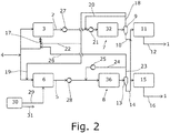
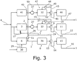
- the proposed method for the synthesis of methanol 1 can be carried out by one of the proposed plants for the synthesis of methanol 1 according to the exemplary embodiments in FIG Figs. 1 to 3 and 6 be performed.
- the proposed method for the synthesis of methanol 1 is initially based on the proposed system for the synthesis of methanol 1 from the Fig. 1 explained.
- the exemplary embodiments are basically based on Fig. 2 , 3 and 6 on the embodiment of Fig. 1 , whereby existing differences are pointed out.
- a first fresh gas stream 2 with hydrogen and carbon oxides is obtained in a steam reformer 3 by steam reforming from a carbon-containing energy carrier stream 4.
- the carbon-containing energy carrier flow 4 is here and preferably a natural gas flow comprising methane, ethane and propane.
- a second fresh gas stream 5 with hydrogen and carbon oxides is also obtained in a POX reactor 6 by partial oxidation from the carbon-containing energy carrier stream 4.
- this partial oxidation can be both catalytic partial oxidation and thermal partial oxidation.
- this thermal partial oxidation can also be referred to as non-catalytic partial oxidation.
- the POX reactor 6 is used for thermal partial oxidation.
- the first fresh gas stream 2 is fed to a first methanol reactor arrangement 7 for the synthesis of methanol 1.
- the proposed method for the synthesis of Methanol 1 is characterized in that the second fresh gas stream 5 is fed to a second methanol reactor arrangement 8 for the synthesis of methanol 1.
- a first raw methanol stream 10 is obtained from a first condensation device 9 of the first methanol reactor arrangement 7, which is fed to a first distillation arrangement 11 for obtaining a first methanol product stream 12 comprising the methanol 1.
- a second crude methanol stream 14 is preferably obtained from a second condensation device 13 of the second methanol reactor arrangement 8, which is fed to a second distillation arrangement 15 for obtaining a second methanol product stream 16 comprising the methanol 1.
- the steam reformer 3 is heated by a fired heating device 17.
- This fired heating device 17 is included in the plant for the synthesis of methanol 1.
- the fired heating device 17 is preferably fed by the carbon-containing energy carrier flow 4.
- the heat required for the endothermic reforming reaction can be provided by the fired heating device 17.
- the first fresh gas stream 2 for the methanol synthesis has an excess of hydrogen, so that an excess of hydrogen remains in the residual gas even after it has passed through the first methanol reactor arrangement 7.
- the second fresh gas stream 5 and the residual gas from the second methanol reactor arrangement 8 this is exactly the opposite.
- the proposed method is further characterized in that a residual gas stream 18 with unreacted hydrogen and unreacted carbon oxides is obtained from the first methanol reactor arrangement 7 and that at least some of the unreacted hydrogen is fed to the second methanol reactor arrangement 8 for the synthesis of methanol.
- a residual gas stream 18 with unreacted hydrogen and unreacted carbon oxides is obtained from the first methanol reactor arrangement 7 and that at least some of the unreacted hydrogen is fed to the second methanol reactor arrangement 8 for the synthesis of methanol.
- This fact is also in the Figs. 1 to 3 and 6 shown. It can also be that essentially the complete unreacted hydrogen of the residual gas stream 18 is fed to the second methanol reactor arrangement 8 for the synthesis of methanol.
- the residual gas stream 18 can in particular be obtained from the first condensation device 9 of the first methanol reactor arrangement 7.
- the above part of the unreacted hydrogen can be supplied in various ways and in particular both directly and indirectly.
- a first preferred variant which the embodiments of Fig. 1 and 3 is characterized in that a first substream 19 of the residual gas stream 18 is fed to the second methanol reactor arrangement 8 for the synthesis of methanol.
- the first partial flow 19 is thus fed to the second fresh gas flow 5 here, this being carried out, as shown here and preferably downstream in terms of process technology, to a pressure increase of the second fresh gas flow 5 to be described in more detail.
- part of the total residual gas stream 18 and thus also part of the unreacted carbon oxides of the residual gas stream 18 are fed to the second methanol reactor arrangement 8.
- the first substream 19 is supplied with increased pressure to the second methanol reactor arrangement 8, this variant in the exemplary embodiment in FIG Fig. 3 is realized.
- the pressure in the first methanol reactor arrangement 7 is almost 20 bar higher than the pressure in the second methanol reactor arrangement 8, so that the first substream 19 has a sufficiently high pressure even after passing through the first condensation device.
- the partial flow can also be the entire of the specific flow.
- the prerequisite is that there is no further partial flow of the specific flow.
- a preferred variant according to FIG respective representation in the Fig. 1 and 3 suggest that essentially the complete first substream 19, in particular with essentially constant composition, is fed to the second methanol reactor arrangement 8 for the synthesis of methanol 1.
- the essentially constant composition of the first substream 19 means that this first substream 19 or its components do not undergo any substantial reaction before being fed to the second methanol reactor arrangement 8.
- the variant described below offers an example of a change in the composition.
- a second preferred variant for supplying at least part of the unreacted hydrogen of the residual gas stream 18 and here also part of the unreacted carbon oxides is in the second exemplary embodiment Fig. 2 shown.
- This variant is characterized in that the first partial flow 19 of the residual gas flow 8 is fed to the POX reactor 6 in order to obtain the second fresh gas flow 5.
- this feed can take place indirectly, namely in that the first partial flow 19 is fed to the carbon-containing energy carrier flow before it is fed to the POX reactor 6.
- a feed to the POX reactor 6 is harmless for the reaction in the POX reactor 6, since hydrogen and carbon oxides are the starting materials of the partial oxidation in the POX reactor 6 anyway.
- a third preferred variant for supplying at least part of the unreacted hydrogen of the residual gas stream 18 is in the fourth exemplary embodiment Fig. 6 shown.
- a first partial flow 19 of the residual gas flow 18 is fed to a hydrogen recovery arrangement 52 for recovering a hydrogen-containing flow 53 and a residual flow 54.
- the hydrogen-containing stream 53 is fed to the second methanol reactor arrangement 8 for the synthesis of methanol 1.
- the hydrogen-containing stream 53 is fed to the POX reactor 6 in order to obtain the second fresh gas stream 5.
- the residual flow 54 it is preferably provided that it is fed to the fired heating device 17 in order to feed it. This is in the Fig. 6 also shown.
- the hydrogen recovery arrangement 52 can obtain the hydrogen-containing stream 53 in any desired manner. Basically he can hydrogen-containing stream 53 have any hydrogen content. It is preferred that the hydrogen-containing stream 53 has a higher molar proportion of hydrogen than the residual gas stream 18. However, it can also be that the hydrogen-containing stream 53 consists essentially of hydrogen.
- the residual flow 54 is preferably a flow enriched in molar amounts in methane, carbon monoxide and / or carbon dioxide compared to the residual gas flow 18.
- the hydrogen recovery assembly 52 may include a pressure swing adsorption device (PSA) 55 for recovering the hydrogen-containing stream 53.
- PSA pressure swing adsorption device
- the hydrogen-containing stream is a hydrogen stream 56.
- the hydrogen-containing stream 53 is obtained on a high pressure side of the hydrogen recovery arrangement 52.
- the residual flow 54 is correspondingly obtained on a low-pressure side of the hydrogen recovery arrangement 52.
- This embodiment has the advantage, firstly, that methane in the first substream 19 is practically completely removed from the methanol synthesis cycle. Second, the high degree of purity of hydrogen achieved can be particularly suitable for the desired setting of the stoichiometry. Finally, the hydrogen-containing stream 53 is obtained with a comparatively low pressure loss.
- the hydrogen recovery arrangement 52 can, however, also comprise a membrane arrangement or some other device for recovering the hydrogen-containing stream 53.
- a second substream 20 of the residual gas stream 18 is preferably returned to the first methanol reactor arrangement 7 for the synthesis of methanol.
- This return can be as shown in FIGS Fig. 1 , 2 and 6 take place in that the second partial flow 20 is combined with the first fresh gas flow 2.
- This return of the second partial flow 20 of the residual gas flow 18 is preferably carried out with an increased pressure. As in the Fig. 1 , 2 and 6 shown, this pressure increase can be achieved by a circulation compressor included in the system for the synthesis of methanol 1 21, which increases the pressure of both the second partial flow 20 of the residual gas flow 18 and the first fresh gas flow 2 after they have been combined.
- the circulation compressor 21 is provided for increasing the pressure of the second partial flow 20 of the residual gas flow 18 before it is merged with the first fresh gas flow 2. Such an arrangement is in the embodiment of Fig. 3 shown.
- One possibility of removing the methane not converted in the steam reforming from the methanol synthesis cycle is to use part of the residual gas flow 18 to feed the fired heating device 17. It is therefore preferred that a third partial flow 22 of the residual gas flow 18 is obtained from the residual gas flow 18. This third partial flow 22 of the residual gas flow 18 can then be fed to the fired heating device 17 for feeding the fired heating device 17. In this way, the methane is also utilized and converted into carbon dioxide in the third substream 22.
- the removal from the circuit of that methane which was fed to the second methanol reactor arrangement 8 by the first substream 19 is described below.
- the residual gas flow 18 can be divided as desired with regard to the quantitative proportions.
- a mass flow rate of the third partial flow 22 is lower than a mass flow rate of the first partial flow 19.
- the mass flow rate can be given in particular by the quantity mass per unit of time and in particular by the unit kilograms per minute or tons per hour. It is particularly preferred that the mass throughput of the third partial flow 22 is between 25% and 70% of the mass throughput of the first partial flow 19. More precisely, it can be that the mass flow rate of the third partial flow 22 is between 40% and 50% of the mass flow rate of the first partial flow 19.
- the ratio of the mass flow rate of the third substream 22 to the mass flow rate of the first substream 19 is 30 to 70. It has been found that such a division ratio both brings about a suitable setting of the stoichiometry for the methanol synthesis and allows efficient operation of the fired heating device 17.
- the above-described recirculation of unreacted residual gas for the first methanol reactor arrangement 7 through the second substream 20 of the residual gas flow 18 can also be provided for the second methanol reactor arrangement 8. Accordingly, it is according to the representations in Figs. 1 to 3 and 6, it is preferred that a further residual gas stream 23 with unreacted hydrogen and unreacted carbon oxides is obtained from the second methanol reactor arrangement 8 and that a first substream 24 of the further residual gas flow 23, in particular with increased pressure, is returned to the second methanol reactor arrangement 8 for the synthesis of methanol 1.
- the first partial flow 24 corresponds to the complete further residual gas flow 23. This return is preferably carried out with increased pressure.
- a recycle compressor 25 encompassed by the system for the synthesis of methanol 1 for increasing the pressure of the first partial flow 24 of the further residual gas flow 23 can be provided.
- a second partial flow 26 of the further residual gas flow 23 is obtained. It can be like in the Figs. 1 to 3 and FIG. 6 shows that this second partial flow 26 is obtained upstream of a pressure increase in the further residual gas flow 23 or the first partial flow 24 of the further residual gas flow 23 in terms of process technology. In other words, the second partial flow 26 has not experienced this pressure increase, as a result of which the corresponding device for increasing the pressure, such as the recycling compressor 25 in particular, is relieved with regard to its throughput. It is preferred that the second partial flow 26 of the further residual gas flow 23 is fed to the fired heating device 17 for feeding to the fired heating device 17. In this way, remaining methane can also be removed from the synthesis cycle of the second methanol reactor arrangement 8.
- fresh synthesis gas is obtained at a pressure which is not sufficient for the methanol synthesis or at least not sufficient for an economical operation of the methanol synthesis. It is therefore preferably provided that the first fresh gas stream 2 is increased in pressure by a first synthesis gas compressor 27 before being fed to the first methanol reactor arrangement 7 and that the second fresh gas stream 5 is increased by a second synthesis gas compressor 28 before being fed to the second methanol reactor assembly 8.
- the first synthesis gas compressor 27 and the second synthesis gas compressor 28 are each included in the system for synthesizing methanol 1. Both the first synthesis gas compressor 27 and the second synthesis gas compressor 28 can each have a plurality of compressor stages.
- the first partial flow 19 of the residual gas flow 18 is fed to the second fresh gas flow 5, this preferably taking place downstream of the second synthesis gas compressor 28 in terms of process technology.
- the load on the second synthesis gas compressor 28 is thereby relieved.
- the second synthesis gas compressor 28 has a plurality of compressor stages and the first partial flow 19 is fed to the second fresh gas flow 5 for process technology between two compressor stages of the plurality of compressor stages.
- the POX reactor 6 can also be operated with ambient air.
- a preferred embodiment as in Figs. 1 to 3 and 6 provision is made for an O2 stream 29, consisting essentially of oxygen, to be fed to the POX reactor 6 from an air separation device 30 for obtaining a nitrogen stream 31.
- the nitrogen stream 31 can basically be used for any purpose.
- the use of an O2 stream 29 consisting essentially of oxygen for the POX reactor 6 leads, inter alia, to the second fresh gas stream 5 having only a little nitrogen, which nitrogen is inert for the methanol synthesis. Avoiding this nitrogen in the second fresh gas stream 5 allows the dimensions of the compressors, such as the second synthesis gas compressor 28, to be reduced.
- both the first methanol reactor arrangement 7 and the second methanol reactor arrangement 8 can be designed as desired.
- the first methanol reactor arrangement 7 has one in the Fig. 4 has adiabatic quench reactor 32 for the synthesis of methanol 1 shown in more detail.
- the quench reactor 32 has a multiplicity of feed openings 33a-d, which are spaced apart from one another, for supplying the first fresh gas stream 2.
- the quench reactor likewise has a multiplicity of catalyst beds 34a-d spaced apart from one another for the synthesis of methanol 1. Both the feed openings 33a-d and the catalyst beds 34a-d are preferably along a flow path 35 of the first fresh gas stream 2 through the quench reactor 32 spaced.
- This type of arrangement allows the temperature rise due to the exothermic methanol synthesis reaction in the quench reactor 32 to be limited.
- a quench reactor 32 is preferably suitable when the stoichiometry for the methanol synthesis in the reactor is rather unfavorable, since otherwise the temperature rise cannot be sufficiently limited despite the parceling of the catalyst beds 34a-d and the catalyst is consequently affected.
- the quench reactor 32 is suitable when essentially the superstoichiometric synthesis gas from a steam reforming is used for the methanol synthesis.
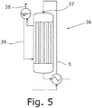
- the second methanol reactor arrangement 8 is one in the Fig. 5 has shown isothermal reactor 36.
- the isothermal reactor 36 has only a single supply opening 37 for supplying the second fresh gas flow 5.
- the heat of reaction of the methanol synthesis when it is generated in the catalyst bed of the isothermal reactor 36 is given off to a water bath.
- Medium-pressure steam 38 is obtained and removed.
- the temperature in the catalyst bed of the isothermal reactor 36 corresponds essentially everywhere to the boiling temperature at the pressure of the cooling water 39.
- the proposed system for the synthesis of methanol and the proposed method for the synthesis of methanol can consist of just one steam reformer 3 and only one POX reactor 6 with the respective corresponding methanol reactor arrangement 7, 8, which is what the exemplary embodiments of FIG Fig. 1 , 2 and 6 corresponds.
- the Fig. 3 shows such an embodiment.
- a corresponding preferred embodiment is characterized in that at least one further fresh gas flow 40 with hydrogen and carbon oxides is obtained in at least one further steam reformer 41 by steam reforming from the carbon-containing energy carrier flow 4, that the at least one further fresh gas flow 40 has at least one further methanol reactor arrangement 42 for the synthesis of methanol 1 is supplied that in each case a further residual gas stream 43 with unreacted hydrogen and unreacted carbon oxides from the at least one further methanol reactor arrangement 42 is obtained and that at least part of the unreacted hydrogen and the unreacted carbon oxides of the respective further residual gas stream 43 is fed to the second methanol reactor arrangement 8 for the synthesis of methanol 1.
- the embodiment of Fig. 3 shows a system for the synthesis of methanol 1, which has exactly one further steam reformer 41 and exactly one further methanol reactor arrangement 42 for the synthesis of methanol 1, so that exactly one further fresh gas stream 40 and exactly one further residual gas stream 43 are obtained.
- the at least one further methanol reactor arrangement 43 each have a further condensation device 44 for receiving a respective further raw methanol stream 45, which is fed to a respective further distillation arrangement 46 for obtaining a respective further methanol product stream 47 comprising methanol 1.
- a first partial flow 50 of the further residual gas flow 43 is preferred and as in FIG Fig. 3 shown fed to the second methanol reactor arrangement 8 for the synthesis of methanol 1.
- a second substream 49 of the further residual gas flow 43 is, however, returned to the further methanol reactor arrangement 42.
- the plant for the synthesis of methanol 1 of the Fig. 3 has in addition preferably and as shown for the second methanol reactor arrangement 8 and the further methanol reactor arrangement 42 a respective one circulation compressor 21 and one further circulation compressor 48.
- the further circulation compressor 48 is set up to increase the pressure of the second partial flow 49 of the further residual gas flow 43.
- the plant for the synthesis of methanol 1 of Fig. 3 as shown and also preferably has a collecting compressor 51 which increases the pressure of both the first partial flow 19 of the residual gas flow 18 and the first partial flow 50 of the further residual gas flow 43 after they have been combined. After merging and increasing the pressure, the first partial flow 19 of the residual gas flow 18 and the first partial flow 50 of the further residual gas flow 43 are preferably combined with the second fresh gas flow 5.
- the proposed method for converting a plant for the synthesis of methanol 1, which plant has at least one steam reformer 3, 41 for obtaining a respective fresh gas stream 2, 5, 40 with hydrogen and carbon oxides by steam reforming from a carbon-containing energy carrier stream 4 and at least one methanol reactor arrangement 7, 8 Synthesis of methanol 1 from a respective fresh gas stream 2, 5, 40, is characterized in that a POX reactor 6 is added to the plant to obtain a fresh gas stream 2, 5, 40.
- the system has exactly one steam reformer 3, 41 and exactly one methanol reactor arrangement 7, 8.
- the plant has a plurality of steam reformers 3, 41 for obtaining a respective fresh gas stream 2, 5, 40 with hydrogen and carbon oxides by steam reforming from a carbon-containing energy carrier stream 4 and a plurality of methanol reactor arrangements 7, 8 for the synthesis of methanol 1 from a each fresh gas stream 2, 5, 40 has.
- This addition of the POX reactor 6 can be done in different ways.
- a steam reformer 3, 41 of the plurality of steam reformers 3, 41 is through a POX reactor 6 to obtain the respective Fresh gas stream 2, 5, 40 replaced.
- the methanol reactor arrangement 7, 8 in the line of the replaced steam reformer 3, 41 can be retained. It is preferred, however, that in addition one methanol reactor arrangement 7, 8 of the plurality of methanol reactor arrangements 7, 8 is replaced by another methanol reactor arrangement 7, 8.
- This other methanol reactor arrangement 7, 8 can, in particular, be an isothermal reactor 36, such as that in FIG Fig. 5 is represented.
- the compressors of the plant are advantageously retained when the POX reactor 6 is added.
- the circulation compressor 21, the recycle compressor 25, the first synthesis gas compressor 27, the second synthesis gas compressor 28 and / or the further circulation compressor 48 are retained.
- adding the POX reactor 6 can also mean adding a new train.
- a preferred variant therefore provides that a further methanol reactor arrangement 7, 8 for the synthesis of methanol 1 is added to the system and that the fish gas stream 2, 5, 40 obtained from the POX reactor 6 is fed to the added further methanol reactor arrangement 7, 8.
- the at least one steam reformer 3, 41 for obtaining a respective fresh gas stream 2, 5, 40 with hydrogen and carbon oxides and the at least one methanol reactor arrangement 7, 8 for the synthesis of methanol 1 substantially continued to operate during the addition of the POX reactor 6.
- the plants for the synthesis of methanol 1 of the Figs. 1 to 3 and 6 can each be understood as the result of the proposed method for converting a plant for the synthesis of methanol 1.
- the POX reactor 6 and the second methanol reactor arrangement 8 which has an isothermal reactor 36, replace a previously provided steam reformer and a previously provided methanol reactor arrangement with a quench reactor.
- the proposed plant for the synthesis of methanol 1 has a steam reformer 3 for obtaining a first fresh gas stream 2 with hydrogen and carbon oxides by steam reforming from a carbon-containing energy carrier stream 4.
- the proposed plant for the synthesis of methanol 1 also has a POX reactor 6 for obtaining a second fresh gas stream 5 with hydrogen and carbon oxides by partial oxidation from the carbon-containing energy carrier stream 4.
- the proposed plant for the synthesis of methanol 1 also has a first methanol reactor arrangement 7 for the synthesis of methanol 1 from the first fresh gas stream 2.
- the proposed plant for the synthesis of methanol 1 is characterized in that the plant has a second methanol reactor arrangement 8 for the synthesis of methanol 1 from the second fresh gas stream 5.
- the proposed plant for the synthesis of methanol 1 is further characterized in that a residual gas stream 18 with unreacted hydrogen and unreacted carbon oxides is obtained from the first methanol reactor arrangement 7 and that at least part of the unreacted hydrogen of the residual gas flow 18 of the second methanol reactor arrangement 8 for the synthesis of methanol 1 is fed.
Landscapes
- Chemical & Material Sciences (AREA)
- Organic Chemistry (AREA)
- Chemical Kinetics & Catalysis (AREA)
- Health & Medical Sciences (AREA)
- General Health & Medical Sciences (AREA)
- Engineering & Computer Science (AREA)
- Combustion & Propulsion (AREA)
- Inorganic Chemistry (AREA)
- Organic Low-Molecular-Weight Compounds And Preparation Thereof (AREA)
- Hydrogen, Water And Hydrids (AREA)
Priority Applications (3)
| Application Number | Priority Date | Filing Date | Title |
|---|---|---|---|
| EP19188698.5A EP3770140B1 (fr) | 2019-07-26 | 2019-07-26 | Procédé et installation de synthèse de méthanol |
| DK19188698.5T DK3770140T3 (da) | 2019-07-26 | 2019-07-26 | Fremgangsmåde og anlæg til syntese af metanol |
| PCT/EP2020/070251 WO2021018630A1 (fr) | 2019-07-26 | 2020-07-17 | Procédé et système pour la synthèse de méthanol |
Applications Claiming Priority (1)
| Application Number | Priority Date | Filing Date | Title |
|---|---|---|---|
| EP19188698.5A EP3770140B1 (fr) | 2019-07-26 | 2019-07-26 | Procédé et installation de synthèse de méthanol |
Publications (2)
| Publication Number | Publication Date |
|---|---|
| EP3770140A1 true EP3770140A1 (fr) | 2021-01-27 |
| EP3770140B1 EP3770140B1 (fr) | 2022-12-14 |
Family
ID=67513329
Family Applications (1)
| Application Number | Title | Priority Date | Filing Date |
|---|---|---|---|
| EP19188698.5A Active EP3770140B1 (fr) | 2019-07-26 | 2019-07-26 | Procédé et installation de synthèse de méthanol |
Country Status (3)
| Country | Link |
|---|---|
| EP (1) | EP3770140B1 (fr) |
| DK (1) | DK3770140T3 (fr) |
| WO (1) | WO2021018630A1 (fr) |
Families Citing this family (1)
| Publication number | Priority date | Publication date | Assignee | Title |
|---|---|---|---|---|
| EP4056531B1 (fr) * | 2021-03-12 | 2023-10-11 | L'Air Liquide, Société Anonyme pour l'Etude et l'Exploitation des Procédés Georges Claude | Appareil et procédé de production de méthanol |
Citations (1)
| Publication number | Priority date | Publication date | Assignee | Title |
|---|---|---|---|---|
| EP2116295A1 (fr) | 2008-04-16 | 2009-11-11 | Methanol Casale S.A. | Procédé de production de méthanol à partir du reformage à la vapeur |
-
2019
- 2019-07-26 EP EP19188698.5A patent/EP3770140B1/fr active Active
- 2019-07-26 DK DK19188698.5T patent/DK3770140T3/da active
-
2020
- 2020-07-17 WO PCT/EP2020/070251 patent/WO2021018630A1/fr not_active Ceased
Patent Citations (1)
| Publication number | Priority date | Publication date | Assignee | Title |
|---|---|---|---|---|
| EP2116295A1 (fr) | 2008-04-16 | 2009-11-11 | Methanol Casale S.A. | Procédé de production de méthanol à partir du reformage à la vapeur |
Also Published As
| Publication number | Publication date |
|---|---|
| DK3770140T3 (da) | 2023-03-13 |
| EP3770140B1 (fr) | 2022-12-14 |
| WO2021018630A1 (fr) | 2021-02-04 |
Similar Documents
| Publication | Publication Date | Title |
|---|---|---|
| EP3205622B1 (fr) | Procede de synthese de methanol | |
| DE60025124T2 (de) | Methode und Vorrichtung zur Wasserstoffherstellung mittels Reformierung | |
| DE69913516T2 (de) | Methanolherstellung | |
| EP3323786B1 (fr) | Procédé de fabrication combinée de méthanol et d'ammoniac | |
| WO2012045766A2 (fr) | Procédé et dispositif de production de gaz riche en méthane à partir de gaz de synthèse | |
| DE60113457T2 (de) | Verfahren und vorrichtung zur herstellung von schwerem wasser | |
| EP3969433A1 (fr) | Procédé et installation de synthèse de méthanol | |
| DE2930214A1 (de) | Verfahren zur selektiven oxydation von kohlenmonoxyd im rahmen einer katalytischen ammoniakherstellung | |
| EP4269332A1 (fr) | Procédé et installation de production de l'ammoniac | |
| EP3744416B1 (fr) | Procédé et installation de synthèse de méthanol | |
| EP3770140B1 (fr) | Procédé et installation de synthèse de méthanol | |
| EP2598618B1 (fr) | Procédé de production de gaz naturel de substitution | |
| EP3816145B1 (fr) | Procédé et système de fabrication de méthanol à partir de gaz de synthèse riche en hydrogène | |
| EP3802410B1 (fr) | Procédé et dispositif de réalisation d'une conversion du gaz à l'eau | |
| DE69801883T2 (de) | Sauerstoff- und stickstoffhinzufügung zur erhöhung der ausbeute der herstellung von ammonia | |
| EP4015496B1 (fr) | Procédé et installation de production de méthanol à partir de gaz de synthèse substochiométrique | |
| DE3518362A1 (de) | Verfahren zur herstellung von methanol | |
| WO2018206705A1 (fr) | Procédé de préparation d'ammoniac | |
| EP3782973B1 (fr) | Procédé et installation de fabrication de méthanol | |
| EP3725760A1 (fr) | Procédé et installation de synthèse de méthanol | |
| EP3523245B1 (fr) | Procédé pour la préparation d'un produit, en particulier d'ammoniac à partir d'un gaz de synthèse | |
| WO2016174126A1 (fr) | Cascades asymétriques en circuit dans la catalyse gazeuse | |
| BE1029714B1 (de) | Ammoniaksynthese mit CO2-neutralem Wasserstoff | |
| EP4686697A1 (fr) | Procédé et installation de fabrication d'un produit de procédé ainsi que procédé de fabrication d'une telle installation | |
| EP4691987A1 (fr) | Procédé et installation de fabrication d'un produit de processus |
Legal Events
| Date | Code | Title | Description |
|---|---|---|---|
| PUAI | Public reference made under article 153(3) epc to a published international application that has entered the european phase |
Free format text: ORIGINAL CODE: 0009012 |
|
| STAA | Information on the status of an ep patent application or granted ep patent |
Free format text: STATUS: THE APPLICATION HAS BEEN PUBLISHED |
|
| AK | Designated contracting states |
Kind code of ref document: A1 Designated state(s): AL AT BE BG CH CY CZ DE DK EE ES FI FR GB GR HR HU IE IS IT LI LT LU LV MC MK MT NL NO PL PT RO RS SE SI SK SM TR |
|
| AX | Request for extension of the european patent |
Extension state: BA ME |
|
| STAA | Information on the status of an ep patent application or granted ep patent |
Free format text: STATUS: REQUEST FOR EXAMINATION WAS MADE |
|
| 17P | Request for examination filed |
Effective date: 20210727 |
|
| RBV | Designated contracting states (corrected) |
Designated state(s): AL AT BE BG CH CY CZ DE DK EE ES FI FR GB GR HR HU IE IS IT LI LT LU LV MC MK MT NL NO PL PT RO RS SE SI SK SM TR |
|
| GRAP | Despatch of communication of intention to grant a patent |
Free format text: ORIGINAL CODE: EPIDOSNIGR1 |
|
| STAA | Information on the status of an ep patent application or granted ep patent |
Free format text: STATUS: GRANT OF PATENT IS INTENDED |
|
| RIC1 | Information provided on ipc code assigned before grant |
Ipc: C01B 3/38 20060101ALI20220610BHEP Ipc: C01B 3/36 20060101ALI20220610BHEP Ipc: B01J 12/00 20060101ALI20220610BHEP Ipc: B01J 8/04 20060101ALI20220610BHEP Ipc: B01J 8/00 20060101ALI20220610BHEP Ipc: C07C 31/04 20060101ALI20220610BHEP Ipc: C07C 29/151 20060101AFI20220610BHEP |
|
| INTG | Intention to grant announced |
Effective date: 20220629 |
|
| GRAS | Grant fee paid |
Free format text: ORIGINAL CODE: EPIDOSNIGR3 |
|
| GRAA | (expected) grant |
Free format text: ORIGINAL CODE: 0009210 |
|
| STAA | Information on the status of an ep patent application or granted ep patent |
Free format text: STATUS: THE PATENT HAS BEEN GRANTED |
|
| AK | Designated contracting states |
Kind code of ref document: B1 Designated state(s): AL AT BE BG CH CY CZ DE DK EE ES FI FR GB GR HR HU IE IS IT LI LT LU LV MC MK MT NL NO PL PT RO RS SE SI SK SM TR |
|
| REG | Reference to a national code |
Ref country code: GB Ref legal event code: FG4D Free format text: NOT ENGLISH |
|
| REG | Reference to a national code |
Ref country code: CH Ref legal event code: EP |
|
| REG | Reference to a national code |
Ref country code: DE Ref legal event code: R096 Ref document number: 502019006515 Country of ref document: DE |
|
| REG | Reference to a national code |
Ref country code: IE Ref legal event code: FG4D Free format text: LANGUAGE OF EP DOCUMENT: GERMAN |
|
| REG | Reference to a national code |
Ref country code: AT Ref legal event code: REF Ref document number: 1537599 Country of ref document: AT Kind code of ref document: T Effective date: 20230115 |
|
| REG | Reference to a national code |
Ref country code: DK Ref legal event code: T3 Effective date: 20230309 |
|
| REG | Reference to a national code |
Ref country code: LT Ref legal event code: MG9D |
|
| REG | Reference to a national code |
Ref country code: NL Ref legal event code: MP Effective date: 20221214 |
|
| PG25 | Lapsed in a contracting state [announced via postgrant information from national office to epo] |
Ref country code: SE Free format text: LAPSE BECAUSE OF FAILURE TO SUBMIT A TRANSLATION OF THE DESCRIPTION OR TO PAY THE FEE WITHIN THE PRESCRIBED TIME-LIMIT Effective date: 20221214 Ref country code: NO Free format text: LAPSE BECAUSE OF FAILURE TO SUBMIT A TRANSLATION OF THE DESCRIPTION OR TO PAY THE FEE WITHIN THE PRESCRIBED TIME-LIMIT Effective date: 20230314 Ref country code: LT Free format text: LAPSE BECAUSE OF FAILURE TO SUBMIT A TRANSLATION OF THE DESCRIPTION OR TO PAY THE FEE WITHIN THE PRESCRIBED TIME-LIMIT Effective date: 20221214 Ref country code: FI Free format text: LAPSE BECAUSE OF FAILURE TO SUBMIT A TRANSLATION OF THE DESCRIPTION OR TO PAY THE FEE WITHIN THE PRESCRIBED TIME-LIMIT Effective date: 20221214 |
|
| PG25 | Lapsed in a contracting state [announced via postgrant information from national office to epo] |
Ref country code: RS Free format text: LAPSE BECAUSE OF FAILURE TO SUBMIT A TRANSLATION OF THE DESCRIPTION OR TO PAY THE FEE WITHIN THE PRESCRIBED TIME-LIMIT Effective date: 20221214 Ref country code: LV Free format text: LAPSE BECAUSE OF FAILURE TO SUBMIT A TRANSLATION OF THE DESCRIPTION OR TO PAY THE FEE WITHIN THE PRESCRIBED TIME-LIMIT Effective date: 20221214 Ref country code: HR Free format text: LAPSE BECAUSE OF FAILURE TO SUBMIT A TRANSLATION OF THE DESCRIPTION OR TO PAY THE FEE WITHIN THE PRESCRIBED TIME-LIMIT Effective date: 20221214 Ref country code: GR Free format text: LAPSE BECAUSE OF FAILURE TO SUBMIT A TRANSLATION OF THE DESCRIPTION OR TO PAY THE FEE WITHIN THE PRESCRIBED TIME-LIMIT Effective date: 20230315 |
|
| PG25 | Lapsed in a contracting state [announced via postgrant information from national office to epo] |
Ref country code: NL Free format text: LAPSE BECAUSE OF FAILURE TO SUBMIT A TRANSLATION OF THE DESCRIPTION OR TO PAY THE FEE WITHIN THE PRESCRIBED TIME-LIMIT Effective date: 20221214 |
|
| PG25 | Lapsed in a contracting state [announced via postgrant information from national office to epo] |
Ref country code: SM Free format text: LAPSE BECAUSE OF FAILURE TO SUBMIT A TRANSLATION OF THE DESCRIPTION OR TO PAY THE FEE WITHIN THE PRESCRIBED TIME-LIMIT Effective date: 20221214 Ref country code: RO Free format text: LAPSE BECAUSE OF FAILURE TO SUBMIT A TRANSLATION OF THE DESCRIPTION OR TO PAY THE FEE WITHIN THE PRESCRIBED TIME-LIMIT Effective date: 20221214 Ref country code: PT Free format text: LAPSE BECAUSE OF FAILURE TO SUBMIT A TRANSLATION OF THE DESCRIPTION OR TO PAY THE FEE WITHIN THE PRESCRIBED TIME-LIMIT Effective date: 20230414 Ref country code: ES Free format text: LAPSE BECAUSE OF FAILURE TO SUBMIT A TRANSLATION OF THE DESCRIPTION OR TO PAY THE FEE WITHIN THE PRESCRIBED TIME-LIMIT Effective date: 20221214 Ref country code: EE Free format text: LAPSE BECAUSE OF FAILURE TO SUBMIT A TRANSLATION OF THE DESCRIPTION OR TO PAY THE FEE WITHIN THE PRESCRIBED TIME-LIMIT Effective date: 20221214 Ref country code: CZ Free format text: LAPSE BECAUSE OF FAILURE TO SUBMIT A TRANSLATION OF THE DESCRIPTION OR TO PAY THE FEE WITHIN THE PRESCRIBED TIME-LIMIT Effective date: 20221214 |
|
| PG25 | Lapsed in a contracting state [announced via postgrant information from national office to epo] |
Ref country code: SK Free format text: LAPSE BECAUSE OF FAILURE TO SUBMIT A TRANSLATION OF THE DESCRIPTION OR TO PAY THE FEE WITHIN THE PRESCRIBED TIME-LIMIT Effective date: 20221214 Ref country code: PL Free format text: LAPSE BECAUSE OF FAILURE TO SUBMIT A TRANSLATION OF THE DESCRIPTION OR TO PAY THE FEE WITHIN THE PRESCRIBED TIME-LIMIT Effective date: 20221214 Ref country code: IS Free format text: LAPSE BECAUSE OF FAILURE TO SUBMIT A TRANSLATION OF THE DESCRIPTION OR TO PAY THE FEE WITHIN THE PRESCRIBED TIME-LIMIT Effective date: 20230414 Ref country code: AL Free format text: LAPSE BECAUSE OF FAILURE TO SUBMIT A TRANSLATION OF THE DESCRIPTION OR TO PAY THE FEE WITHIN THE PRESCRIBED TIME-LIMIT Effective date: 20221214 |
|
| REG | Reference to a national code |
Ref country code: DE Ref legal event code: R097 Ref document number: 502019006515 Country of ref document: DE |
|
| PLBE | No opposition filed within time limit |
Free format text: ORIGINAL CODE: 0009261 |
|
| STAA | Information on the status of an ep patent application or granted ep patent |
Free format text: STATUS: NO OPPOSITION FILED WITHIN TIME LIMIT |
|
| 26N | No opposition filed |
Effective date: 20230915 |
|
| PG25 | Lapsed in a contracting state [announced via postgrant information from national office to epo] |
Ref country code: SI Free format text: LAPSE BECAUSE OF FAILURE TO SUBMIT A TRANSLATION OF THE DESCRIPTION OR TO PAY THE FEE WITHIN THE PRESCRIBED TIME-LIMIT Effective date: 20221214 |
|
| PG25 | Lapsed in a contracting state [announced via postgrant information from national office to epo] |
Ref country code: MC Free format text: LAPSE BECAUSE OF FAILURE TO SUBMIT A TRANSLATION OF THE DESCRIPTION OR TO PAY THE FEE WITHIN THE PRESCRIBED TIME-LIMIT Effective date: 20221214 |
|
| PG25 | Lapsed in a contracting state [announced via postgrant information from national office to epo] |
Ref country code: MC Free format text: LAPSE BECAUSE OF FAILURE TO SUBMIT A TRANSLATION OF THE DESCRIPTION OR TO PAY THE FEE WITHIN THE PRESCRIBED TIME-LIMIT Effective date: 20221214 |
|
| REG | Reference to a national code |
Ref country code: CH Ref legal event code: PL |
|
| REG | Reference to a national code |
Ref country code: BE Ref legal event code: MM Effective date: 20230731 |
|
| PG25 | Lapsed in a contracting state [announced via postgrant information from national office to epo] |
Ref country code: LU Free format text: LAPSE BECAUSE OF NON-PAYMENT OF DUE FEES Effective date: 20230726 |
|
| GBPC | Gb: european patent ceased through non-payment of renewal fee |
Effective date: 20230726 |
|
| PG25 | Lapsed in a contracting state [announced via postgrant information from national office to epo] |
Ref country code: LU Free format text: LAPSE BECAUSE OF NON-PAYMENT OF DUE FEES Effective date: 20230726 |
|
| REG | Reference to a national code |
Ref country code: IE Ref legal event code: MM4A |
|
| PG25 | Lapsed in a contracting state [announced via postgrant information from national office to epo] |
Ref country code: GB Free format text: LAPSE BECAUSE OF NON-PAYMENT OF DUE FEES Effective date: 20230726 Ref country code: CH Free format text: LAPSE BECAUSE OF NON-PAYMENT OF DUE FEES Effective date: 20230731 |
|
| PG25 | Lapsed in a contracting state [announced via postgrant information from national office to epo] |
Ref country code: IT Free format text: LAPSE BECAUSE OF FAILURE TO SUBMIT A TRANSLATION OF THE DESCRIPTION OR TO PAY THE FEE WITHIN THE PRESCRIBED TIME-LIMIT Effective date: 20221214 Ref country code: FR Free format text: LAPSE BECAUSE OF NON-PAYMENT OF DUE FEES Effective date: 20230731 Ref country code: BE Free format text: LAPSE BECAUSE OF NON-PAYMENT OF DUE FEES Effective date: 20230731 |
|
| PG25 | Lapsed in a contracting state [announced via postgrant information from national office to epo] |
Ref country code: IE Free format text: LAPSE BECAUSE OF NON-PAYMENT OF DUE FEES Effective date: 20230726 |
|
| PG25 | Lapsed in a contracting state [announced via postgrant information from national office to epo] |
Ref country code: IE Free format text: LAPSE BECAUSE OF NON-PAYMENT OF DUE FEES Effective date: 20230726 |
|
| PG25 | Lapsed in a contracting state [announced via postgrant information from national office to epo] |
Ref country code: BG Free format text: LAPSE BECAUSE OF FAILURE TO SUBMIT A TRANSLATION OF THE DESCRIPTION OR TO PAY THE FEE WITHIN THE PRESCRIBED TIME-LIMIT Effective date: 20221214 |
|
| PG25 | Lapsed in a contracting state [announced via postgrant information from national office to epo] |
Ref country code: BG Free format text: LAPSE BECAUSE OF FAILURE TO SUBMIT A TRANSLATION OF THE DESCRIPTION OR TO PAY THE FEE WITHIN THE PRESCRIBED TIME-LIMIT Effective date: 20221214 |
|
| PG25 | Lapsed in a contracting state [announced via postgrant information from national office to epo] |
Ref country code: CY Free format text: LAPSE BECAUSE OF FAILURE TO SUBMIT A TRANSLATION OF THE DESCRIPTION OR TO PAY THE FEE WITHIN THE PRESCRIBED TIME-LIMIT; INVALID AB INITIO Effective date: 20190726 |
|
| PG25 | Lapsed in a contracting state [announced via postgrant information from national office to epo] |
Ref country code: HU Free format text: LAPSE BECAUSE OF FAILURE TO SUBMIT A TRANSLATION OF THE DESCRIPTION OR TO PAY THE FEE WITHIN THE PRESCRIBED TIME-LIMIT; INVALID AB INITIO Effective date: 20190726 |
|
| REG | Reference to a national code |
Ref country code: AT Ref legal event code: MM01 Ref document number: 1537599 Country of ref document: AT Kind code of ref document: T Effective date: 20240726 |
|
| PGFP | Annual fee paid to national office [announced via postgrant information from national office to epo] |
Ref country code: DK Payment date: 20250723 Year of fee payment: 7 Ref country code: DE Payment date: 20250722 Year of fee payment: 7 |
|
| PG25 | Lapsed in a contracting state [announced via postgrant information from national office to epo] |
Ref country code: AT Free format text: LAPSE BECAUSE OF NON-PAYMENT OF DUE FEES Effective date: 20240726 |
|
| PG25 | Lapsed in a contracting state [announced via postgrant information from national office to epo] |
Ref country code: TR Free format text: LAPSE BECAUSE OF FAILURE TO SUBMIT A TRANSLATION OF THE DESCRIPTION OR TO PAY THE FEE WITHIN THE PRESCRIBED TIME-LIMIT Effective date: 20221214 |
|
| PGFP | Annual fee paid to national office [announced via postgrant information from national office to epo] |
Ref country code: AT Payment date: 20260410 Year of fee payment: 5 |