EP3770368A1 - Structure de porte pliante - Google Patents
Structure de porte pliante Download PDFInfo
- Publication number
- EP3770368A1 EP3770368A1 EP19830896.7A EP19830896A EP3770368A1 EP 3770368 A1 EP3770368 A1 EP 3770368A1 EP 19830896 A EP19830896 A EP 19830896A EP 3770368 A1 EP3770368 A1 EP 3770368A1
- Authority
- EP
- European Patent Office
- Prior art keywords
- fixed seat
- pulley
- sliding bracket
- latch
- upright column
- Prior art date
- Legal status (The legal status is an assumption and is not a legal conclusion. Google has not performed a legal analysis and makes no representation as to the accuracy of the status listed.)
- Granted
Links
Images


Classifications
-
- E—FIXED CONSTRUCTIONS
- E05—LOCKS; KEYS; WINDOW OR DOOR FITTINGS; SAFES
- E05D—HINGES OR SUSPENSION DEVICES FOR DOORS, WINDOWS OR WINGS
- E05D15/00—Suspension arrangements for wings
- E05D15/26—Suspension arrangements for wings for folding wings
-
- E—FIXED CONSTRUCTIONS
- E05—LOCKS; KEYS; WINDOW OR DOOR FITTINGS; SAFES
- E05B—LOCKS; ACCESSORIES THEREFOR; HANDCUFFS
- E05B65/00—Locks or fastenings for special use
- E05B65/08—Locks or fastenings for special use for sliding wings
- E05B65/087—Locks or fastenings for special use for sliding wings the bolts sliding parallel to the wings
- E05B65/0876—Locks or fastenings for special use for sliding wings the bolts sliding parallel to the wings cooperating with the slide guide, e.g. the rail
-
- E—FIXED CONSTRUCTIONS
- E06—DOORS, WINDOWS, SHUTTERS, OR ROLLER BLINDS IN GENERAL; LADDERS
- E06B—FIXED OR MOVABLE CLOSURES FOR OPENINGS IN BUILDINGS, VEHICLES, FENCES OR LIKE ENCLOSURES IN GENERAL, e.g. DOORS, WINDOWS, BLINDS, GATES
- E06B3/00—Window sashes, door leaves, or like elements for closing wall or like openings; Layout of fixed or moving closures, e.g. windows in wall or like openings; Features of rigidly-mounted outer frames relating to the mounting of wing frames
- E06B3/32—Arrangements of wings characterised by the manner of movement; Arrangements of movable wings in openings; Features of wings or frames relating solely to the manner of movement of the wing
- E06B3/48—Wings connected at their edges, e.g. foldable wings
- E06B3/481—Wings foldable in a zig-zag manner or bi-fold wings
-
- E—FIXED CONSTRUCTIONS
- E06—DOORS, WINDOWS, SHUTTERS, OR ROLLER BLINDS IN GENERAL; LADDERS
- E06B—FIXED OR MOVABLE CLOSURES FOR OPENINGS IN BUILDINGS, VEHICLES, FENCES OR LIKE ENCLOSURES IN GENERAL, e.g. DOORS, WINDOWS, BLINDS, GATES
- E06B3/00—Window sashes, door leaves, or like elements for closing wall or like openings; Layout of fixed or moving closures, e.g. windows in wall or like openings; Features of rigidly-mounted outer frames relating to the mounting of wing frames
- E06B3/32—Arrangements of wings characterised by the manner of movement; Arrangements of movable wings in openings; Features of wings or frames relating solely to the manner of movement of the wing
- E06B3/50—Arrangements of wings characterised by the manner of movement; Arrangements of movable wings in openings; Features of wings or frames relating solely to the manner of movement of the wing with more than one kind of movement
- E06B3/5009—Arrangements of wings characterised by the manner of movement; Arrangements of movable wings in openings; Features of wings or frames relating solely to the manner of movement of the wing with more than one kind of movement where the sliding and rotating movements are necessarily performed simultaneously
- E06B3/5018—Arrangements of wings characterised by the manner of movement; Arrangements of movable wings in openings; Features of wings or frames relating solely to the manner of movement of the wing with more than one kind of movement where the sliding and rotating movements are necessarily performed simultaneously where the pivot axis slides during pivoting of the wing
-
- E—FIXED CONSTRUCTIONS
- E06—DOORS, WINDOWS, SHUTTERS, OR ROLLER BLINDS IN GENERAL; LADDERS
- E06B—FIXED OR MOVABLE CLOSURES FOR OPENINGS IN BUILDINGS, VEHICLES, FENCES OR LIKE ENCLOSURES IN GENERAL, e.g. DOORS, WINDOWS, BLINDS, GATES
- E06B3/00—Window sashes, door leaves, or like elements for closing wall or like openings; Layout of fixed or moving closures, e.g. windows in wall or like openings; Features of rigidly-mounted outer frames relating to the mounting of wing frames
- E06B3/32—Arrangements of wings characterised by the manner of movement; Arrangements of movable wings in openings; Features of wings or frames relating solely to the manner of movement of the wing
- E06B3/50—Arrangements of wings characterised by the manner of movement; Arrangements of movable wings in openings; Features of wings or frames relating solely to the manner of movement of the wing with more than one kind of movement
- E06B3/509—Arrangements of wings characterised by the manner of movement; Arrangements of movable wings in openings; Features of wings or frames relating solely to the manner of movement of the wing with more than one kind of movement where one of the sliding and rotating movements necessarily precedes the other
-
- E—FIXED CONSTRUCTIONS
- E06—DOORS, WINDOWS, SHUTTERS, OR ROLLER BLINDS IN GENERAL; LADDERS
- E06B—FIXED OR MOVABLE CLOSURES FOR OPENINGS IN BUILDINGS, VEHICLES, FENCES OR LIKE ENCLOSURES IN GENERAL, e.g. DOORS, WINDOWS, BLINDS, GATES
- E06B3/00—Window sashes, door leaves, or like elements for closing wall or like openings; Layout of fixed or moving closures, e.g. windows in wall or like openings; Features of rigidly-mounted outer frames relating to the mounting of wing frames
- E06B3/92—Doors or windows extensible when set in position
- E06B3/922—Doors or windows extensible when set in position with several wings opening horizontally towards the same side of the opening and each closing a separate part of the opening
- E06B3/924—Doors or windows extensible when set in position with several wings opening horizontally towards the same side of the opening and each closing a separate part of the opening positioned in one plane when closed
-
- E—FIXED CONSTRUCTIONS
- E05—LOCKS; KEYS; WINDOW OR DOOR FITTINGS; SAFES
- E05B—LOCKS; ACCESSORIES THEREFOR; HANDCUFFS
- E05B65/00—Locks or fastenings for special use
- E05B65/0085—Locks or fastenings for special use for folding wings, e.g. bi-fold wings
-
- E—FIXED CONSTRUCTIONS
- E05—LOCKS; KEYS; WINDOW OR DOOR FITTINGS; SAFES
- E05D—HINGES OR SUSPENSION DEVICES FOR DOORS, WINDOWS OR WINGS
- E05D15/00—Suspension arrangements for wings
- E05D15/26—Suspension arrangements for wings for folding wings
- E05D2015/268—Suspension arrangements for wings for folding wings the wings being successively folded
-
- E—FIXED CONSTRUCTIONS
- E05—LOCKS; KEYS; WINDOW OR DOOR FITTINGS; SAFES
- E05Y—INDEXING SCHEME ASSOCIATED WITH SUBCLASSES E05D AND E05F, RELATING TO CONSTRUCTION ELEMENTS, ELECTRIC CONTROL, POWER SUPPLY, POWER SIGNAL OR TRANSMISSION, USER INTERFACES, MOUNTING OR COUPLING, DETAILS, ACCESSORIES, AUXILIARY OPERATIONS NOT OTHERWISE PROVIDED FOR, APPLICATION THEREOF
- E05Y2201/00—Constructional elements; Accessories therefor
- E05Y2201/60—Suspension or transmission members; Accessories therefor
- E05Y2201/622—Suspension or transmission members elements
- E05Y2201/64—Carriers
-
- E—FIXED CONSTRUCTIONS
- E05—LOCKS; KEYS; WINDOW OR DOOR FITTINGS; SAFES
- E05Y—INDEXING SCHEME ASSOCIATED WITH SUBCLASSES E05D AND E05F, RELATING TO CONSTRUCTION ELEMENTS, ELECTRIC CONTROL, POWER SUPPLY, POWER SIGNAL OR TRANSMISSION, USER INTERFACES, MOUNTING OR COUPLING, DETAILS, ACCESSORIES, AUXILIARY OPERATIONS NOT OTHERWISE PROVIDED FOR, APPLICATION THEREOF
- E05Y2201/00—Constructional elements; Accessories therefor
- E05Y2201/60—Suspension or transmission members; Accessories therefor
- E05Y2201/622—Suspension or transmission members elements
- E05Y2201/684—Rails; Tracks
-
- E—FIXED CONSTRUCTIONS
- E05—LOCKS; KEYS; WINDOW OR DOOR FITTINGS; SAFES
- E05Y—INDEXING SCHEME ASSOCIATED WITH SUBCLASSES E05D AND E05F, RELATING TO CONSTRUCTION ELEMENTS, ELECTRIC CONTROL, POWER SUPPLY, POWER SIGNAL OR TRANSMISSION, USER INTERFACES, MOUNTING OR COUPLING, DETAILS, ACCESSORIES, AUXILIARY OPERATIONS NOT OTHERWISE PROVIDED FOR, APPLICATION THEREOF
- E05Y2900/00—Application of doors, windows, wings or fittings thereof
- E05Y2900/10—Application of doors, windows, wings or fittings thereof for buildings or parts thereof
- E05Y2900/13—Type of wing
- E05Y2900/132—Doors
-
- E—FIXED CONSTRUCTIONS
- E06—DOORS, WINDOWS, SHUTTERS, OR ROLLER BLINDS IN GENERAL; LADDERS
- E06B—FIXED OR MOVABLE CLOSURES FOR OPENINGS IN BUILDINGS, VEHICLES, FENCES OR LIKE ENCLOSURES IN GENERAL, e.g. DOORS, WINDOWS, BLINDS, GATES
- E06B3/00—Window sashes, door leaves, or like elements for closing wall or like openings; Layout of fixed or moving closures, e.g. windows in wall or like openings; Features of rigidly-mounted outer frames relating to the mounting of wing frames
- E06B3/04—Wing frames not characterised by the manner of movement
- E06B3/263—Frames with special provision for insulation
- E06B3/26301—Frames with special provision for insulation with prefabricated insulating strips between two metal section members
- E06B3/26303—Frames with special provision for insulation with prefabricated insulating strips between two metal section members with thin strips, e.g. defining a hollow space between the metal section members
-
- E—FIXED CONSTRUCTIONS
- E06—DOORS, WINDOWS, SHUTTERS, OR ROLLER BLINDS IN GENERAL; LADDERS
- E06B—FIXED OR MOVABLE CLOSURES FOR OPENINGS IN BUILDINGS, VEHICLES, FENCES OR LIKE ENCLOSURES IN GENERAL, e.g. DOORS, WINDOWS, BLINDS, GATES
- E06B5/00—Doors, windows, or like closures for special purposes; Border constructions therefor
- E06B5/10—Doors, windows, or like closures for special purposes; Border constructions therefor for protection against air-raid or other war-like action; for other protective purposes
- E06B5/12—Doors, windows, or like closures for special purposes; Border constructions therefor for protection against air-raid or other war-like action; for other protective purposes against air pressure, explosion, or gas
-
- E—FIXED CONSTRUCTIONS
- E06—DOORS, WINDOWS, SHUTTERS, OR ROLLER BLINDS IN GENERAL; LADDERS
- E06B—FIXED OR MOVABLE CLOSURES FOR OPENINGS IN BUILDINGS, VEHICLES, FENCES OR LIKE ENCLOSURES IN GENERAL, e.g. DOORS, WINDOWS, BLINDS, GATES
- E06B7/00—Special arrangements or measures in connection with doors or windows
- E06B7/14—Measures for draining-off condensed water or water leaking-in frame members for draining off condensation water, throats at the bottom of a sash
-
- E—FIXED CONSTRUCTIONS
- E06—DOORS, WINDOWS, SHUTTERS, OR ROLLER BLINDS IN GENERAL; LADDERS
- E06B—FIXED OR MOVABLE CLOSURES FOR OPENINGS IN BUILDINGS, VEHICLES, FENCES OR LIKE ENCLOSURES IN GENERAL, e.g. DOORS, WINDOWS, BLINDS, GATES
- E06B7/00—Special arrangements or measures in connection with doors or windows
- E06B7/16—Sealing arrangements on wings or parts co-operating with the wings
- E06B7/22—Sealing arrangements on wings or parts co-operating with the wings by means of elastic edgings, e.g. elastic rubber tubes; by means of resilient edgings, e.g. felt or plush strips, resilient metal strips
- E06B7/23—Plastic, sponge rubber, or like strips or tubes
- E06B7/2305—Plastic, sponge rubber, or like strips or tubes with an integrally formed part for fixing the edging
- E06B7/2307—Plastic, sponge rubber, or like strips or tubes with an integrally formed part for fixing the edging with a single sealing-line or -plane between the wing and the part co-operating with the wing
Definitions
- the present invention relates to the field of window and door fittings for buildings, and in particular to a folding door structure.
- Doors and windows are divided into enclosure members or partition members according to their positions, and have different design requirements, such as heat preservation, thermal insulation, sound insulation, wind resistance, water resistance, fire resistance and other functions. Related measured data have indicated that, in cold areas, the loss of heat from the gaps of windows or doors accounts for about 25% of the whole heat consumption. On one hand, the airtightness of windows and doors is very important in the energy conservation design. On the other hand, since doors and windows are important constituent parts of the enclosure structures of buildings, the doors and windows mounted on an outer surface of a building need to be able to resist against the high wind pressure in the windy weather, need to be able to resist against rain in the rainy weather, and preferably can have thermal insulation when the temperature changes in different seasons.
- Folding doors are mainly suitable for workshops, shopping malls, office buildings, exhibition halls, home decoration or other occasions, and serve as partitions or screens.
- the folding doors may be used as interior doors or exterior doors, and may have the effects of thermal insulation, dust prevention, noise reduction, sound insulation, shielding and the like.
- the folding doors are beautiful in appearance, novel in style, easy to use and easy to push or pull, and effectively save the floor space.
- the upper and lower sliding members in the connection mounting structure between two adjacent door leaves have the functions of guiding and limiting in a left-right direction, sliding back and forth and bearing the stress, moreover heat insulating strips are provided in an inner cavity of the door leaf profile to realize heat insulation.
- a folding door structure which is able to improve, or at least to a certain extent, the reliability of a connection mounting structure between two adjacent door leaves so that the connection mounting structure can resist against the high wind pressure.
- the present invention employs the following technical solutions.
- a folding door structure is provided, including: a fixed frame, an upper slide and a lower slide located on the fixed frame, and a plurality of door leaves sandwiched between the upper slide and the lower slide.
- the folding door structure further includes an upright column, an upper sliding bracket, a lower sliding bracket and a first lock component;
- the door leaves are hinged with the upright column;
- the upper sliding bracket is located at an upper end of the upright column and includes an upper pulley and an upper fixed seat, and the upper pulley is fixedly arranged on the upper fixed seat and slidingly provided in the upper slide;
- the lower sliding bracket is located at a lower end of the upright column and includes a lower pulley and a lower fixed seat, and the lower pulley is fixedly arranged on the lower fixed seat and slidingly provided in the lower slide; both the upper fixed seat and the lower fixed seat are fixedly arranged on the upright column, and the upright column is sandwiched between the upper slide and the lower slide through the upper pulley and the lower pulley;
- the first lock component includes a first latch, which is mounted inside the upright column, and both ends of which are extended out from the top and bottom of the upright column to insert into the upper slide and/or the lower slide.
- the folding door structure further includes a central column and a second lock component; two opposite sides of the central column are hinged to the door leaves, respectively; the second lock component includes a second latch and a switch handle; and, the second latch is located within the central column, and the switch handle is located outside the central column, in order to control the second latch to extend out from an end of the central column and then clamp the upper slide and/or the lower slide when the door leaves are closed.
- the upper slide includes an upper guide groove in an inverted U-shape;
- the upper sliding bracket includes a left upper sliding bracket and a right upper sliding bracket;
- the left upper sliding bracket includes a left upper guide pulley and a left upper fixed seat, with the left upper guide pulley being fixedly arranged on the left upper fixed seat;
- the right upper sliding bracket includes a right upper guide pulley and a right upper fixed seat, with the right upper guide pulley being fixedly arranged on the right upper fixed seat;
- the left upper fixed seat and the right upper fixed seat are symmetrical in an inverted L-shape and are symmetrically fixed on two opposite wide sides of the upright column;
- the left upper guide pulley and the right upper guide pulley are arranged in a line and slidingly provided in the upper guide groove;
- the first latch includes a first upper latch; and, an extended head of the first upper latch is located in the middle of the left upper guide pulley and the right upper guide pulley and resisted against an inner side
- the lower slide includes a lower guide groove in a U-shape; tops of two side walls of the lower guide groove are installed with slide rails;
- the lower sliding bracket includes a left lower sliding bracket and a right lower sliding bracket;
- the left lower sliding bracket includes a left lower pulley and a left lower fixed seat, with the left lower pulley being fixedly arranged on the left lower fixed seat;
- the right lower sliding bracket includes a right lower pulley and a right lower fixed seat, with the right lower pulley being fixedly arranged on the right lower fixed seat;
- the left lower fixed seat and the right lower fixed seat are symmetrical in an L-shape and are symmetrically fixed on two opposite wide sides of the upright column;
- each of the left lower pulley and the right lower pulley includes a lower guide pulley and two lower bearing rollers;
- the lower guide pulleys are arranged in a line and slidingly provided in the lower guide groove, and the lower bearing rollers are slidingly provided in the lower guide rail
- the upper sliding bracket further includes an upper hinge sheet which is hinged to the upper fixed seat and fixedly connected to the door leaves; and/or, the lower sliding bracket further includes a lower hinge sheet which is hinged to the lower fixed seat and fixedly connected to the door leaves.
- the upright column is of a thermal-break aluminum profile structure including an outer cavity, a middle cavity and an inner cavity, and the first latch is mounted in the middle cavity.
- the folding door structure further includes a reinforcement core which is located in the outer cavity to reinforce the upright column.
- the central column is of a thermal-break aluminum profile structure including an outer cavity, a middle cavity and an inner cavity, and the second latch is mounted inside the middle cavity; and the folding door structure further includes a reinforcement core which is located in the outer cavity to reinforce the central column.
- the folding door structure further includes a positioning component which is fixedly provided on the folded opposite faces of two adjacent door leaves to fix a relative position between the two adjacent leaves during folding.
- drip edge profiles are provided on an outer side of an upper portion of the fixed frame, and drainage holes are formed on an outer side face of a lower portion of the fixed frame.
- gaskets for sealing the folding door include interlocked compression gaskets.
- a first latch can correspondingly fix the upright column, so that the stress environment of the upper sliding bracket and the lower sliding bracket is improved. Therefore, when the folding door structure is used as an exterior door, the reliability of a connection mounting structure between two adjacent door leaves can be improved, the fixation effect becomes better, and the resistance against the high wind pressure becomes better. Consequently, it is beneficial to prolong the service life of the upper sliding bracket and the lower sliding bracket, it is advantageous for the fixation, airtightness and water resistance of the door leaves, and it is also advantageous for the wide application of the folding door as the exterior door on external walls of buildings. By providing a central column and a second lock component, the reliability of the connection mounting structure between two adjacent door leaves can be further improved, and the resistance against the high wind pressure becomes better.
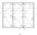
- the folding door in this embodiment includes a door frame, door leaves, a connecting column, an upper sliding bracket 2, a lower sliding bracket 3 and a first lock component.
- the door frame includes an upper frame 11, a lower frame 12, a left frame 13 and a right frame 14.
- the upper frame 11 includes an upper guide groove 111 in an inverted U-shape.
- the lower frame 12 includes a bearing rail 120 and a lower guide groove 121.
- the lower guide groove 121 is in a U-shape, and tops of two side walls of the lower guide groove 121 are installed with rail 120.
- the door leaves include a first door leaf 16, a second door leaf 17 and a third door leaf 18.
- the third door leaf 18 is hinged to the left frame 13 via a hinge 1
- both the third door leaf 18 and the second door leaf 17 are hinged to a central column 9
- an upright column 10 as one connecting column is located between the second door leaf 17 and the first door leaf 16
- left and right opposite wide sides of the upright column are hinged to the second door leaf 17 and the first door leaf 16 respectively.
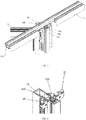
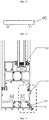
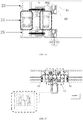
- An upper end of the upright column 10 is slidingly connected to the upper frame 11 via the upper sliding bracket 2, while a lower end thereof is slidingly connected to the lower frame 12 via the lower sliding bracket 3. Specifically, as shown in Figs.
- the upper sliding bracket 2 is located at the upper end of the upright column 10, and includes an upper guide pulley 20 and an upper fixed seat 22.
- the upper guide pulley 20 is fixedly arranged on the fixed seat 22 and slidingly provided in the upper guide groove 111.
- the lower sliding bracket 3 is located at the lower end of the upright column 10, and includes a lower guide pulley 30, bearing rollers 32 and a lower fixed seat 33.
- the lower guide pullet 30 is fixedly arranged on the lower fixed seat 33 and slidingly provided in the lower guide groove 121.
- the bearing rollers 32 are fixedly provided on two opposite sides of the bottom of the lower fixed seat 33 and slidingly provided on the bearing rail 120.
- Both the upper fixed seat 22 and the lower fixed seat 33 are fixedly provided on the upright column 10, and the upright column 10 is sandwiched between the upper frame 11 and the lower frame 12 through the upper pulley and the lower pulley.
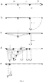
- the upright column 10 can slide along the upper frame 11 and the lower frame 12, so that the door leaves are folded.
- the upper sliding bracket 2 includes a left upper sliding bracket 201 and a right upper sliding bracket 202.
- the left upper sliding bracket 201 includes a left upper guide pulley 20 and a left upper fixed seat.
- the left upper guide pulley 20 is fixedly arranged on the left upper fixed seat.
- the right upper sliding bracket 202 includes a right upper guide pulley 20 and a right upper fixed seat.
- the right upper guide pulley 20 is fixedly arranged on the right upper fixed seat.
- the left upper fixed seat and the right upper fixed seat are symmetrical in an inverted L-shape, and are symmetrically fixed on two opposite wide sides of the upright column 10.
- the left upper guide pulley 20 and the right upper guide pulley 20 are arranged in a line and slidingly provided in the upper guide groove 111.
- the first latch includes an upper latch 190.
- a head of the upper latch 190 is located in the middle of the left upper guide pulley 20 and the right upper guide pulley 20, and can resist against an inner side face of the upper guide groove 111 when being extended outward. This structure greatly enhances the resistance against the high wind pressure of the upper sliding bracket.
- the lower sliding bracket 3 includes a left lower sliding bracket 301 and a right lower sliding bracket 302.
- the left lower sliding bracket 301 includes a left lower guide pulley 30 and a left lower fixed seat.
- the left lower guide pulley 30 is fixedly arranged on the left lower fixed seat.
- the right lower sliding bracket 302 includes a right lower guide pulley 30 and a right lower fixed seat.
- the right lower guide pulley 30 is fixedly arranged on the right lower fixed seat.
- the left lower fixed seat and the right lower fixed seat are symmetrical in an L-shape, and are symmetrically fixed on two opposite wide sides of the upright column 10.
- the left lower guide pulley 30 and the right lower guide pulley 30 are arranged in a line and slidingly provided in the lower guide groove 121.
- the bearing rollers 32 are slidingly provided on the bearing rail 120.
- the first latch includes a lower latch 191.
- a head of the lower latch 191 is located in the middle of the left lower guide pulley 30 and the right lower guide pulley 30, and can resist against an inner side face of the lower guide groove 121 when being extended outward. This structure greatly enhances the resistance against the high wind pressure of the lower sliding bracket.
- the first lock component includes a first latch.
- the first latch includes an upper latch and a lower latch.
- the upright column 10 is preferably of a thermal-break aluminum profile structure including an outer cavity 103, a middle cavity 102 and an inner cavity 101.
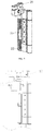
- the upper latch 190 is horizontally limited by a guiding sleeve 19 and axially fixed in the middle cavity 102. Referring to Fig. 11 , an end of the upper latch 190 is extended out from the upper end of the upright column 10 and inserted into an inner wall of the upper guide groove 111.
- the lower latch 191 can be arranged with reference to the arrangement of the upper latch 190.
- the lower latch 191 is horizontally limited by the guiding sleeve 19 and axially fixed in the middle cavity 102. Referring to Fig. 12 , an end of the lower latch 191 is extended out from the lower end of the upright column 10 and inserted into an inner wall of the lower guide groove 121.
- the folding door further includes a reinforcement core 100.
- the reinforcement core 100 is preferably located in the outer cavity 103 to reinforce the upright column 10.As a preferred implementation of the outer cavity 103, the outer cavity 103 is lengthened. This structure is advantageous for the accommodation of the reinforcement core 100 and the reinforcement, heat insulation and resistance against the high wind pressure of the connecting column.
- a lock handle 7 is provided on the first door leaf 16 in order to control the cooperative locking with the right frame 14.
- the lock handle 7 is preferably a latch bolt capable of controlling an upper position, a middle position and a lower position to realize the cooperative locking with the upper frame 11, the right frame 14 and the lower frame 12, so that the guard against theft, the resistance against wind and the water resistance of the whole door leaves are improved.
- a U-shaped handle 8 is provided on the third door leaf 18 close to the second door leaf 17, so that it is convenient for folding and pushing/pulling the door leaves.
- the upright column 10 can also be further reinforced according to different requirements on the resistance against the wind pressure.
- the extended end of the upper latch 190 and/or the lower latch 191 is resisted against and inserted into the side wall of the upper guide groove 111 and/or the lower guide groove 121, the wind pressure can be endured, and the upright column 10 is fixed correspondingly.
- the stress environment of the upper sliding bracket 2 and the lower sliding bracket 3 is improved. Therefore, when the folding door is used as an exterior door, the reliability of the connection mounting structure between two adjacent door leaves can be improved, the high wind pressure can be resisted and the fixation effect becomes better.
- the upright column 10 when there is a plurality of door leaves, is preferably arranged between two adjacent door leaves, and spaced from the two adjacent door leaves.
- the upright column 10 preferably, the second door leaf 17 and the first door leaf 16 are used as a door leaf unit, and the door leaves are assembled.
- a plurality of door leaf units can be hinged to each other, and the door leaves are hinged to the door leaf units.
- the specific number of door leaves can be rationally set according to the width of the door opening. Therefore, there may be various combinations, for example, an odd number + an odd number, an even number + an even number, an odd number + an even number, an odd number + 0, or an even number + 0.
- the door leaves can be pushed /pulled and folded in an indoor direction, or can be pushed/pulled and folded in an outdoor direction.
- the number of door leaves in each door leaf unit is not limited to 2, and there may be more door leaves.
- the folding door further includes a second lock component.
- the second lock component includes a second latch and a positioning handle 15.
- the connecting column further includes a central column 9. Left and right opposite wide sides of the central column 9 are hinged to the second door leaf 17 and the third door leaf 18 via hinges 1, respectively, and the central column 9 is located between the left frame 13 and the upright column 10.
- the second latch can be implemented partially with reference to the implementation of the upper latch 190 and/or the lower latch 191.
- the upper latch 190 and/or the lower latch 191 serves as a latch bolt capable of being telescopically controlled by the positioning handle 15 and is provided in the central column 9, and the positioning handle 15 is provided outside the central column 9 in order to control the second latch to extend out from an end of the central column 9 and then insert into the upper guide groove 111 and/or the lower guide groove 121 when the door leaves are closed.
- the central column 9 can refer to the upright column 10.
- the central column 9 is of a thermal-break aluminum profile structure, correspondingly including an outer cavity, a middle cavity and an inner cavity.
- the second latch is located in the middle cavity.
- the central column 9 can also be further reinforced with reference to the implementation of the reinforcement core 100 according to different requirements on the resistance against the wind pressure.
- the central column 9 can move in a folding direction of the door leaves.
- the folding door is closed and after the second latch is extended out and fixed, the wind pressure can be endured, and the central column 9 is fixed correspondingly. Therefore, when the folding door is used as an exterior door, the reliability of the connection mounting structure between two adjacent door leaves can be further improved, the high wind pressure can be resisted, the airtightness and the water resistance are enhanced, and the fixation effect becomes better.
- any two adjacent door leaves are hinged to the connecting column, and the lock component is used for locking the position of the connecting column relative to the door frame in a direction of wind pressure (a direction perpendicular to the folding door).
- a direction of wind pressure a direction perpendicular to the folding door.
- the split-type upper sliding bracket 2 further includes an upper hinge sheet 21 which is hinged to the upper fixed seat 22 and fixedly connected to the door leaves; and/or, the split-type lower sliding bracket 3 further includes a lower hinge sheet 31 which is hinged to the lower fixed seat 33 and fixedly connected to the door leaves.
- This structure has a sliding connection function and a hinge joint function. By integrating a conventional hinge with a sliding member, the assembly quality and efficiency can be improved.
- the bearing roller 32 is preferably made of stainless steel in order to ensure the sufficient strength of the accessories and improve the corrosion resistance.
- the folding door further includes a positioning component.
- the positioning component includes a clamping member 4 and a fastener 5.
- the clamping member 4 and the fastener 5 are fixedly provided on opposite folding faces of the second door leaf 17 and the first door leaf 16, respectively, in order to fix the relative position of the two adjacent door leaves in the folded state.
- a drip edge profile 110 is provided on an outer side face of the upper frame 11 in order to prevent rain from permeating into the inner side of the door leaves along the door frame.
- Drainage holes 6 are formed on an outer side face of the lower frame 12, and the drainage holes 6 are communicated with a water collector of the lower frame 12 to drain accumulated water in the lower frame 12.
- a drainage hole cover 60 is provided on the drainage holes 6 to prevent rain from flowing back when in a typhoon.
- Gaskets 61 on the bottoms of the door leaves are located at positions where the door leaves adjoin the door frame, so that the outside surface of the lower frame 12 is covered when the door leaves are completely closed. Accordingly, while realizing the water resistance, the pressure in the water collector is the same as that outside the water collector, so that it is advantageous for the drainage of accumulated water, and the wind resistance, water resistance and energy conservation effects of the folding door are improved.
- the main structure of the door frame and the door leaves, and the connecting column are preferably made of thermal-break aluminum profile.
- the thermal-break aluminum profile includes an inner aluminum profile 23, a heat insulating bar 24 and an outer aluminum profile 25.
- the heat insulating bar 24 is located between the inner aluminum profile 23 and the outer aluminum profile 25 to form a three-cavity structure.
- the inner aluminum profile 23 and the outer aluminum profile 25 can realize different colors of indoor and outdoor aluminum profiles, or can realize the uniformity of the color of the external wall and the indoor decoration. Meanwhile, the heat preservation and heat insulation performances are improved, and the sound insulation and noise reduction effects of the whole folding door are also improved.
- Waterproof frame gaskets 64 are mounted and compressed by clamps, so that the waterproof effect becomes better.
- interlocked compression gaskets 63 are transversely or vertically mounted inside gaps formed when the folding door is closed. Better fixation and sealing effects are realized by the mutually matched structure of inner and outer interlocked compression gaskets 63. Therefore, in the case of a big difference in air pressure, water penetration can be avoided, and the waterproof and energy-saving effects of the folding door are further improved.
- folding door structure of the present invention is not limited to implementations as doors, and can also be implemented as windows.
- the implementations as windows shall also fall into the protection scope of the present invention.
- inventive patent has been described illustratively above, apparently, the implementations of the inventive patent is not limited by the above implementations. Various improvements obtained by using the method concepts and technical solutions of the inventive patent or direct application of the concepts and technical solutions of the inventive patent in other occasions without any improvement shall fall into the protection scope of the present invention.
Landscapes
- Engineering & Computer Science (AREA)
- Civil Engineering (AREA)
- Structural Engineering (AREA)
- Mechanical Engineering (AREA)
- Extensible Doors And Revolving Doors (AREA)
Applications Claiming Priority (2)
| Application Number | Priority Date | Filing Date | Title |
|---|---|---|---|
| CN201821058936.XU CN208564327U (zh) | 2018-07-04 | 2018-07-04 | 一种折叠门结构 |
| PCT/CN2019/094362 WO2020007286A1 (fr) | 2018-07-04 | 2019-07-02 | Structure de porte pliante |
Publications (4)
| Publication Number | Publication Date |
|---|---|
| EP3770368A1 true EP3770368A1 (fr) | 2021-01-27 |
| EP3770368A4 EP3770368A4 (fr) | 2021-12-22 |
| EP3770368C0 EP3770368C0 (fr) | 2024-03-20 |
| EP3770368B1 EP3770368B1 (fr) | 2024-03-20 |
Family
ID=65490243
Family Applications (1)
| Application Number | Title | Priority Date | Filing Date |
|---|---|---|---|
| EP19830896.7A Active EP3770368B1 (fr) | 2018-07-04 | 2019-07-02 | Structure de porte pliante |
Country Status (5)
| Country | Link |
|---|---|
| US (1) | US11434679B2 (fr) |
| EP (1) | EP3770368B1 (fr) |
| CN (1) | CN208564327U (fr) |
| AU (1) | AU2019299619B2 (fr) |
| WO (1) | WO2020007286A1 (fr) |
Cited By (1)
| Publication number | Priority date | Publication date | Assignee | Title |
|---|---|---|---|---|
| US11434679B2 (en) * | 2018-07-04 | 2022-09-06 | Cyber Top Trading Limited | Folding door structure |
Families Citing this family (9)
| Publication number | Priority date | Publication date | Assignee | Title |
|---|---|---|---|---|
| US10988969B1 (en) * | 2018-10-09 | 2021-04-27 | Theron Clark Harley | Screening apparatus and assembly |
| US11486177B2 (en) * | 2019-06-06 | 2022-11-01 | Endura Products, Llc | Continuous locking hinge assemblies and folding door assemblies including the same |
| US20230374837A1 (en) * | 2020-03-23 | 2023-11-23 | Stoper Endüstriyel Ürünler Sanayi Ticaret Limited Sirketi | Motorized sliding folding panel mechanism |
| CN112523652A (zh) * | 2020-11-30 | 2021-03-19 | 江西朝阳机械有限公司 | 一种两折折叠门生产工艺 |
| CA3211342A1 (fr) * | 2021-03-09 | 2022-09-15 | Matthew Brown | Porte pliante pour systeme de paroi mobile |
| CN112983162B (zh) * | 2021-03-10 | 2024-07-02 | 广东图特精密五金科技股份有限公司 | 铰链安装自锁组件、滑轮组快装机构和折叠推拉门 |
| KR102329685B1 (ko) * | 2021-03-12 | 2021-11-22 | (주)동광명품도어 | 다중 접이식 방화장치 |
| CN113229719B (zh) * | 2021-05-25 | 2022-06-24 | 宁波方太厨具有限公司 | 一种用于烹饪设备的门组件及蒸烤烹饪设备 |
| US12523086B2 (en) | 2023-01-27 | 2026-01-13 | Endura Products, Llc | Continuous locking hinge assemblies and folding door assemblies including the same |
Family Cites Families (19)
| Publication number | Priority date | Publication date | Assignee | Title |
|---|---|---|---|---|
| US4386645A (en) * | 1981-02-10 | 1983-06-07 | Cornell Iron Works, Inc. | Side folding closure |
| US4922987A (en) * | 1989-01-09 | 1990-05-08 | Woodfold-Marco Mfg., Inc. | Secure type folding door |
| CA2004649C (fr) * | 1989-12-05 | 1993-07-06 | Jeffrey Pasternak | Poteau d'assemblage a charnieres pour portes pliantes |
| US5472037A (en) * | 1994-03-25 | 1995-12-05 | Hoffman; Robert E. | Reinforced accordion-type folding shutters |
| WO2008089104A2 (fr) * | 2007-01-12 | 2008-07-24 | Pella Architectural Products, Inc., D/ B/A Pacific Architectural Millwork | Système de portes repliables |
| FR2987063B1 (fr) * | 2012-02-20 | 2017-02-24 | Midi Moulages Plast | Porte sectionnelle coulissante a deplacement lateral comportant un portillon pivotant en section d'extremite |
| KR20130099661A (ko) * | 2012-02-29 | 2013-09-06 | 안중식 | 슬라이드 접철형 도어의 센터롤러 장치 |
| CN202500423U (zh) * | 2012-03-07 | 2012-10-24 | 傅海 | 一种折叠门窗用上吊轮 |
| US9359806B2 (en) * | 2014-03-19 | 2016-06-07 | Gregory Header | Combination marine and stop frame glazed panel and method for the same |
| KR101745401B1 (ko) * | 2015-03-31 | 2017-06-12 | (주)이지폴딩 | 미닫이용 창틀 위에 직접 설치할 수 있는 폴딩도어 |
| US9695623B2 (en) * | 2015-09-09 | 2017-07-04 | Derek Keith Thomas | Powered folding doors |
| US9879471B2 (en) * | 2015-09-30 | 2018-01-30 | Woodfold Mfg., Inc. | Reinforced folding door and hinge assembly |
| CN205172333U (zh) * | 2015-11-23 | 2016-04-20 | 北京市腾美骐科技发展有限公司 | 木包铝推拉折叠门 |
| CN206190139U (zh) * | 2016-10-19 | 2017-05-24 | 北京金博田门窗有限公司 | 一种新型折叠门的紧固结构 |
| DE102016125655B3 (de) * | 2016-12-23 | 2018-06-21 | Solarlux Gmbh | Fixiervorrichtung für insbesondere Glasfaltanlagen |
| KR20170001691A (ko) * | 2016-12-23 | 2017-01-04 | (주)이지폴딩 | 바닥면을 철거하지 않고 시공이 가능한 폴딩도어 |
| CN107575131B (zh) * | 2017-10-31 | 2023-06-30 | 河北奥润顺达窗业有限公司 | 一种铝合金折叠推拉门窗 |
| CN108035637A (zh) * | 2018-01-17 | 2018-05-15 | 中山市佰迪克五金制品有限公司 | 一种合页机构及包括该合页机构的折叠门 |
| CN208564327U (zh) * | 2018-07-04 | 2019-03-01 | 创科贸易有限公司 | 一种折叠门结构 |
-
2018
- 2018-07-04 CN CN201821058936.XU patent/CN208564327U/zh active Active
- 2018-10-31 US US16/177,399 patent/US11434679B2/en active Active
-
2019
- 2019-07-02 EP EP19830896.7A patent/EP3770368B1/fr active Active
- 2019-07-02 AU AU2019299619A patent/AU2019299619B2/en active Active
- 2019-07-02 WO PCT/CN2019/094362 patent/WO2020007286A1/fr not_active Ceased
Cited By (1)
| Publication number | Priority date | Publication date | Assignee | Title |
|---|---|---|---|---|
| US11434679B2 (en) * | 2018-07-04 | 2022-09-06 | Cyber Top Trading Limited | Folding door structure |
Also Published As
| Publication number | Publication date |
|---|---|
| EP3770368C0 (fr) | 2024-03-20 |
| AU2019299619A1 (en) | 2020-10-29 |
| EP3770368B1 (fr) | 2024-03-20 |
| US11434679B2 (en) | 2022-09-06 |
| AU2019299619B2 (en) | 2022-01-13 |
| EP3770368A4 (fr) | 2021-12-22 |
| CN208564327U (zh) | 2019-03-01 |
| US20190078367A1 (en) | 2019-03-14 |
| WO2020007286A1 (fr) | 2020-01-09 |
Similar Documents
| Publication | Publication Date | Title |
|---|---|---|
| EP3770368B1 (fr) | Structure de porte pliante | |
| US20120227329A1 (en) | Reversible sliding glass door | |
| US20220090439A1 (en) | Panel frame joints, sills, and other elements of folding door systems with shootbolt system | |
| US20130008089A1 (en) | Sliding panel systems | |
| CN112832627B (zh) | 一种用于门窗橱柜的可紧闭式侧拉结构 | |
| KR20120040339A (ko) | 커튼월형 창호 | |
| KR101466870B1 (ko) | 구조변경이 용이한 평레일 창호장치 | |
| CN101949250B (zh) | 一种铝合金内开内倒窗框架的中梃与外框结构 | |
| CN219387640U (zh) | 窄边框的窗结构 | |
| KR102094368B1 (ko) | 멀티 테크 단열복합창 | |
| CN201865502U (zh) | 一种铝合金内开内倒窗框架的中梃与外框结构 | |
| CN216043337U (zh) | 一种外开式窗 | |
| KR20140105894A (ko) | 구조변경이 용이한 평레일 창호장치 | |
| US20170268274A1 (en) | Tilt and turn or fixed frame window with appearance of traditional single-hung or double-hung window from exterior | |
| CN210003119U (zh) | 一种防盗推拉窗 | |
| CN105840058A (zh) | 一种隔热多层玻璃窗 | |
| CN222716802U (zh) | 一种可开启的铝合金格栅 | |
| CN206468204U (zh) | 一种断桥平开窗 | |
| CN219101085U (zh) | 一种木铝复合提升推拉门 | |
| CN105625884A (zh) | 一种全玻式隐框推拉窗 | |
| KR20160109714A (ko) | 단열 및 방풍성이 향상된 창호 | |
| CN222731458U (zh) | 一种可开启铝合金格栅的型材结构 | |
| CN221256536U (zh) | 一种铝合金推拉窗 | |
| CN110552595A (zh) | 一种全景门 | |
| CN220815393U (zh) | 一种六轨隔热隔音断桥推拉窗 |
Legal Events
| Date | Code | Title | Description |
|---|---|---|---|
| STAA | Information on the status of an ep patent application or granted ep patent |
Free format text: STATUS: THE INTERNATIONAL PUBLICATION HAS BEEN MADE |
|
| PUAI | Public reference made under article 153(3) epc to a published international application that has entered the european phase |
Free format text: ORIGINAL CODE: 0009012 |
|
| STAA | Information on the status of an ep patent application or granted ep patent |
Free format text: STATUS: REQUEST FOR EXAMINATION WAS MADE |
|
| 17P | Request for examination filed |
Effective date: 20201021 |
|
| AK | Designated contracting states |
Kind code of ref document: A1 Designated state(s): AL AT BE BG CH CY CZ DE DK EE ES FI FR GB GR HR HU IE IS IT LI LT LU LV MC MK MT NL NO PL PT RO RS SE SI SK SM TR |
|
| AX | Request for extension of the european patent |
Extension state: BA ME |
|
| DAV | Request for validation of the european patent (deleted) | ||
| DAX | Request for extension of the european patent (deleted) | ||
| A4 | Supplementary search report drawn up and despatched |
Effective date: 20211119 |
|
| RIC1 | Information provided on ipc code assigned before grant |
Ipc: E05D 15/26 20060101ALI20211115BHEP Ipc: E06B 3/48 20060101AFI20211115BHEP |
|
| GRAP | Despatch of communication of intention to grant a patent |
Free format text: ORIGINAL CODE: EPIDOSNIGR1 |
|
| STAA | Information on the status of an ep patent application or granted ep patent |
Free format text: STATUS: GRANT OF PATENT IS INTENDED |
|
| INTG | Intention to grant announced |
Effective date: 20240103 |
|
| GRAS | Grant fee paid |
Free format text: ORIGINAL CODE: EPIDOSNIGR3 |
|
| GRAA | (expected) grant |
Free format text: ORIGINAL CODE: 0009210 |
|
| STAA | Information on the status of an ep patent application or granted ep patent |
Free format text: STATUS: THE PATENT HAS BEEN GRANTED |
|
| AK | Designated contracting states |
Kind code of ref document: B1 Designated state(s): AL AT BE BG CH CY CZ DE DK EE ES FI FR GB GR HR HU IE IS IT LI LT LU LV MC MK MT NL NO PL PT RO RS SE SI SK SM TR |
|
| REG | Reference to a national code |
Ref country code: GB Ref legal event code: FG4D |
|
| REG | Reference to a national code |
Ref country code: CH Ref legal event code: EP |
|
| REG | Reference to a national code |
Ref country code: IE Ref legal event code: FG4D |
|
| REG | Reference to a national code |
Ref country code: DE Ref legal event code: R096 Ref document number: 602019048727 Country of ref document: DE |
|
| U01 | Request for unitary effect filed |
Effective date: 20240419 |
|
| U07 | Unitary effect registered |
Designated state(s): AT BE BG DE DK EE FI FR IT LT LU LV MT NL PT SE SI Effective date: 20240425 |
|
| PGFP | Annual fee paid to national office [announced via postgrant information from national office to epo] |
Ref country code: GB Payment date: 20240606 Year of fee payment: 6 |
|
| U20 | Renewal fee for the european patent with unitary effect paid |
Year of fee payment: 6 Effective date: 20240606 |
|
| PG25 | Lapsed in a contracting state [announced via postgrant information from national office to epo] |
Ref country code: GR Free format text: LAPSE BECAUSE OF FAILURE TO SUBMIT A TRANSLATION OF THE DESCRIPTION OR TO PAY THE FEE WITHIN THE PRESCRIBED TIME-LIMIT Effective date: 20240621 |
|
| PG25 | Lapsed in a contracting state [announced via postgrant information from national office to epo] |
Ref country code: HR Free format text: LAPSE BECAUSE OF FAILURE TO SUBMIT A TRANSLATION OF THE DESCRIPTION OR TO PAY THE FEE WITHIN THE PRESCRIBED TIME-LIMIT Effective date: 20240320 Ref country code: RS Free format text: LAPSE BECAUSE OF FAILURE TO SUBMIT A TRANSLATION OF THE DESCRIPTION OR TO PAY THE FEE WITHIN THE PRESCRIBED TIME-LIMIT Effective date: 20240620 |
|
| PG25 | Lapsed in a contracting state [announced via postgrant information from national office to epo] |
Ref country code: RS Free format text: LAPSE BECAUSE OF FAILURE TO SUBMIT A TRANSLATION OF THE DESCRIPTION OR TO PAY THE FEE WITHIN THE PRESCRIBED TIME-LIMIT Effective date: 20240620 Ref country code: NO Free format text: LAPSE BECAUSE OF FAILURE TO SUBMIT A TRANSLATION OF THE DESCRIPTION OR TO PAY THE FEE WITHIN THE PRESCRIBED TIME-LIMIT Effective date: 20240620 Ref country code: HR Free format text: LAPSE BECAUSE OF FAILURE TO SUBMIT A TRANSLATION OF THE DESCRIPTION OR TO PAY THE FEE WITHIN THE PRESCRIBED TIME-LIMIT Effective date: 20240320 Ref country code: GR Free format text: LAPSE BECAUSE OF FAILURE TO SUBMIT A TRANSLATION OF THE DESCRIPTION OR TO PAY THE FEE WITHIN THE PRESCRIBED TIME-LIMIT Effective date: 20240621 |
|
| PG25 | Lapsed in a contracting state [announced via postgrant information from national office to epo] |
Ref country code: IS Free format text: LAPSE BECAUSE OF FAILURE TO SUBMIT A TRANSLATION OF THE DESCRIPTION OR TO PAY THE FEE WITHIN THE PRESCRIBED TIME-LIMIT Effective date: 20240720 |
|
| PG25 | Lapsed in a contracting state [announced via postgrant information from national office to epo] |
Ref country code: SM Free format text: LAPSE BECAUSE OF FAILURE TO SUBMIT A TRANSLATION OF THE DESCRIPTION OR TO PAY THE FEE WITHIN THE PRESCRIBED TIME-LIMIT Effective date: 20240320 |
|
| PG25 | Lapsed in a contracting state [announced via postgrant information from national office to epo] |
Ref country code: ES Free format text: LAPSE BECAUSE OF FAILURE TO SUBMIT A TRANSLATION OF THE DESCRIPTION OR TO PAY THE FEE WITHIN THE PRESCRIBED TIME-LIMIT Effective date: 20240320 |
|
| PG25 | Lapsed in a contracting state [announced via postgrant information from national office to epo] |
Ref country code: CZ Free format text: LAPSE BECAUSE OF FAILURE TO SUBMIT A TRANSLATION OF THE DESCRIPTION OR TO PAY THE FEE WITHIN THE PRESCRIBED TIME-LIMIT Effective date: 20240320 |
|
| PG25 | Lapsed in a contracting state [announced via postgrant information from national office to epo] |
Ref country code: PL Free format text: LAPSE BECAUSE OF FAILURE TO SUBMIT A TRANSLATION OF THE DESCRIPTION OR TO PAY THE FEE WITHIN THE PRESCRIBED TIME-LIMIT Effective date: 20240320 |
|
| PG25 | Lapsed in a contracting state [announced via postgrant information from national office to epo] |
Ref country code: SK Free format text: LAPSE BECAUSE OF FAILURE TO SUBMIT A TRANSLATION OF THE DESCRIPTION OR TO PAY THE FEE WITHIN THE PRESCRIBED TIME-LIMIT Effective date: 20240320 |
|
| PG25 | Lapsed in a contracting state [announced via postgrant information from national office to epo] |
Ref country code: SM Free format text: LAPSE BECAUSE OF FAILURE TO SUBMIT A TRANSLATION OF THE DESCRIPTION OR TO PAY THE FEE WITHIN THE PRESCRIBED TIME-LIMIT Effective date: 20240320 Ref country code: SK Free format text: LAPSE BECAUSE OF FAILURE TO SUBMIT A TRANSLATION OF THE DESCRIPTION OR TO PAY THE FEE WITHIN THE PRESCRIBED TIME-LIMIT Effective date: 20240320 Ref country code: RO Free format text: LAPSE BECAUSE OF FAILURE TO SUBMIT A TRANSLATION OF THE DESCRIPTION OR TO PAY THE FEE WITHIN THE PRESCRIBED TIME-LIMIT Effective date: 20240320 Ref country code: PL Free format text: LAPSE BECAUSE OF FAILURE TO SUBMIT A TRANSLATION OF THE DESCRIPTION OR TO PAY THE FEE WITHIN THE PRESCRIBED TIME-LIMIT Effective date: 20240320 Ref country code: IS Free format text: LAPSE BECAUSE OF FAILURE TO SUBMIT A TRANSLATION OF THE DESCRIPTION OR TO PAY THE FEE WITHIN THE PRESCRIBED TIME-LIMIT Effective date: 20240720 Ref country code: ES Free format text: LAPSE BECAUSE OF FAILURE TO SUBMIT A TRANSLATION OF THE DESCRIPTION OR TO PAY THE FEE WITHIN THE PRESCRIBED TIME-LIMIT Effective date: 20240320 Ref country code: CZ Free format text: LAPSE BECAUSE OF FAILURE TO SUBMIT A TRANSLATION OF THE DESCRIPTION OR TO PAY THE FEE WITHIN THE PRESCRIBED TIME-LIMIT Effective date: 20240320 |
|
| REG | Reference to a national code |
Ref country code: DE Ref legal event code: R097 Ref document number: 602019048727 Country of ref document: DE |
|
| PLBE | No opposition filed within time limit |
Free format text: ORIGINAL CODE: 0009261 |
|
| STAA | Information on the status of an ep patent application or granted ep patent |
Free format text: STATUS: NO OPPOSITION FILED WITHIN TIME LIMIT |
|
| PG25 | Lapsed in a contracting state [announced via postgrant information from national office to epo] |
Ref country code: MC Free format text: LAPSE BECAUSE OF FAILURE TO SUBMIT A TRANSLATION OF THE DESCRIPTION OR TO PAY THE FEE WITHIN THE PRESCRIBED TIME-LIMIT Effective date: 20240320 |
|
| 26N | No opposition filed |
Effective date: 20241223 |
|
| REG | Reference to a national code |
Ref country code: CH Ref legal event code: PL |
|
| PG25 | Lapsed in a contracting state [announced via postgrant information from national office to epo] |
Ref country code: CH Free format text: LAPSE BECAUSE OF NON-PAYMENT OF DUE FEES Effective date: 20240731 |
|
| PG25 | Lapsed in a contracting state [announced via postgrant information from national office to epo] |
Ref country code: IE Free format text: LAPSE BECAUSE OF NON-PAYMENT OF DUE FEES Effective date: 20240702 |
|
| PG25 | Lapsed in a contracting state [announced via postgrant information from national office to epo] |
Ref country code: CY Free format text: LAPSE BECAUSE OF FAILURE TO SUBMIT A TRANSLATION OF THE DESCRIPTION OR TO PAY THE FEE WITHIN THE PRESCRIBED TIME-LIMIT; INVALID AB INITIO Effective date: 20190702 |
|
| PG25 | Lapsed in a contracting state [announced via postgrant information from national office to epo] |
Ref country code: HU Free format text: LAPSE BECAUSE OF FAILURE TO SUBMIT A TRANSLATION OF THE DESCRIPTION OR TO PAY THE FEE WITHIN THE PRESCRIBED TIME-LIMIT; INVALID AB INITIO Effective date: 20190702 |
|
| GBPC | Gb: european patent ceased through non-payment of renewal fee |
Effective date: 20250702 |
|
| U90 | Renewal fees not paid: noting of loss of rights |
Free format text: RENEWAL FEE NOT PAID FOR YEAR 07 Effective date: 20260223 |
|
| PG25 | Lapsed in a contracting state [announced via postgrant information from national office to epo] |
Ref country code: GB Free format text: LAPSE BECAUSE OF NON-PAYMENT OF DUE FEES Effective date: 20250702 |