EP3770426A1 - Verfahren und vorrichtung zur computerimplementierten überwachung einer oder mehrerer windturbinen in einem windpark - Google Patents
Verfahren und vorrichtung zur computerimplementierten überwachung einer oder mehrerer windturbinen in einem windpark Download PDFInfo
- Publication number
- EP3770426A1 EP3770426A1 EP19188519.3A EP19188519A EP3770426A1 EP 3770426 A1 EP3770426 A1 EP 3770426A1 EP 19188519 A EP19188519 A EP 19188519A EP 3770426 A1 EP3770426 A1 EP 3770426A1
- Authority
- EP
- European Patent Office
- Prior art keywords
- wind
- wind turbine
- rotor
- upper section
- image
- Prior art date
- Legal status (The legal status is an assumption and is not a legal conclusion. Google has not performed a legal analysis and makes no representation as to the accuracy of the status listed.)
- Pending
Links
Images
Classifications
-
- F—MECHANICAL ENGINEERING; LIGHTING; HEATING; WEAPONS; BLASTING
- F03—MACHINES OR ENGINES FOR LIQUIDS; WIND, SPRING, OR WEIGHT MOTORS; PRODUCING MECHANICAL POWER OR A REACTIVE PROPULSIVE THRUST, NOT OTHERWISE PROVIDED FOR
- F03D—WIND MOTORS
- F03D17/00—Monitoring or testing of wind motors, e.g. diagnostics
-
- F—MECHANICAL ENGINEERING; LIGHTING; HEATING; WEAPONS; BLASTING
- F03—MACHINES OR ENGINES FOR LIQUIDS; WIND, SPRING, OR WEIGHT MOTORS; PRODUCING MECHANICAL POWER OR A REACTIVE PROPULSIVE THRUST, NOT OTHERWISE PROVIDED FOR
- F03D—WIND MOTORS
- F03D17/00—Monitoring or testing of wind motors, e.g. diagnostics
- F03D17/001—Inspection
- F03D17/003—Inspection characterised by using optical devices, e.g. lidar or cameras
-
- F—MECHANICAL ENGINEERING; LIGHTING; HEATING; WEAPONS; BLASTING
- F03—MACHINES OR ENGINES FOR LIQUIDS; WIND, SPRING, OR WEIGHT MOTORS; PRODUCING MECHANICAL POWER OR A REACTIVE PROPULSIVE THRUST, NOT OTHERWISE PROVIDED FOR
- F03D—WIND MOTORS
- F03D17/00—Monitoring or testing of wind motors, e.g. diagnostics
- F03D17/005—Monitoring or testing of wind motors, e.g. diagnostics using computation methods, e.g. neural networks
-
- F—MECHANICAL ENGINEERING; LIGHTING; HEATING; WEAPONS; BLASTING
- F03—MACHINES OR ENGINES FOR LIQUIDS; WIND, SPRING, OR WEIGHT MOTORS; PRODUCING MECHANICAL POWER OR A REACTIVE PROPULSIVE THRUST, NOT OTHERWISE PROVIDED FOR
- F03D—WIND MOTORS
- F03D17/00—Monitoring or testing of wind motors, e.g. diagnostics
- F03D17/027—Monitoring or testing of wind motors, e.g. diagnostics characterised by the component being monitored or tested
- F03D17/029—Blade pitch or yaw drive systems, e.g. pitch or yaw angle
-
- G—PHYSICS
- G06—COMPUTING OR CALCULATING; COUNTING
- G06T—IMAGE DATA PROCESSING OR GENERATION, IN GENERAL
- G06T7/00—Image analysis
- G06T7/0002—Inspection of images, e.g. flaw detection
- G06T7/0004—Industrial image inspection
-
- G—PHYSICS
- G06—COMPUTING OR CALCULATING; COUNTING
- G06T—IMAGE DATA PROCESSING OR GENERATION, IN GENERAL
- G06T7/00—Image analysis
- G06T7/70—Determining position or orientation of objects or cameras
- G06T7/73—Determining position or orientation of objects or cameras using feature-based methods
-
- F—MECHANICAL ENGINEERING; LIGHTING; HEATING; WEAPONS; BLASTING
- F03—MACHINES OR ENGINES FOR LIQUIDS; WIND, SPRING, OR WEIGHT MOTORS; PRODUCING MECHANICAL POWER OR A REACTIVE PROPULSIVE THRUST, NOT OTHERWISE PROVIDED FOR
- F03D—WIND MOTORS
- F03D7/00—Controlling wind motors
- F03D7/02—Controlling wind motors the wind motors having rotation axis substantially parallel to the air flow entering the rotor
- F03D7/0204—Controlling wind motors the wind motors having rotation axis substantially parallel to the air flow entering the rotor for orientation in relation to wind direction
-
- F—MECHANICAL ENGINEERING; LIGHTING; HEATING; WEAPONS; BLASTING
- F03—MACHINES OR ENGINES FOR LIQUIDS; WIND, SPRING, OR WEIGHT MOTORS; PRODUCING MECHANICAL POWER OR A REACTIVE PROPULSIVE THRUST, NOT OTHERWISE PROVIDED FOR
- F03D—WIND MOTORS
- F03D7/00—Controlling wind motors
- F03D7/02—Controlling wind motors the wind motors having rotation axis substantially parallel to the air flow entering the rotor
- F03D7/04—Automatic control; Regulation
- F03D7/042—Automatic control; Regulation by means of an electrical or electronic controller
- F03D7/043—Automatic control; Regulation by means of an electrical or electronic controller characterised by the type of control logic
- F03D7/045—Automatic control; Regulation by means of an electrical or electronic controller characterised by the type of control logic with model-based controls
-
- F—MECHANICAL ENGINEERING; LIGHTING; HEATING; WEAPONS; BLASTING
- F03—MACHINES OR ENGINES FOR LIQUIDS; WIND, SPRING, OR WEIGHT MOTORS; PRODUCING MECHANICAL POWER OR A REACTIVE PROPULSIVE THRUST, NOT OTHERWISE PROVIDED FOR
- F03D—WIND MOTORS
- F03D7/00—Controlling wind motors
- F03D7/02—Controlling wind motors the wind motors having rotation axis substantially parallel to the air flow entering the rotor
- F03D7/04—Automatic control; Regulation
- F03D7/042—Automatic control; Regulation by means of an electrical or electronic controller
- F03D7/048—Automatic control; Regulation by means of an electrical or electronic controller controlling wind farms
-
- F—MECHANICAL ENGINEERING; LIGHTING; HEATING; WEAPONS; BLASTING
- F05—INDEXING SCHEMES RELATING TO ENGINES OR PUMPS IN VARIOUS SUBCLASSES OF CLASSES F01-F04
- F05B—INDEXING SCHEME RELATING TO WIND, SPRING, WEIGHT, INERTIA OR LIKE MOTORS, TO MACHINES OR ENGINES FOR LIQUIDS COVERED BY SUBCLASSES F03B, F03D AND F03G
- F05B2260/00—Function
- F05B2260/80—Diagnostics
-
- F—MECHANICAL ENGINEERING; LIGHTING; HEATING; WEAPONS; BLASTING
- F05—INDEXING SCHEMES RELATING TO ENGINES OR PUMPS IN VARIOUS SUBCLASSES OF CLASSES F01-F04
- F05B—INDEXING SCHEME RELATING TO WIND, SPRING, WEIGHT, INERTIA OR LIKE MOTORS, TO MACHINES OR ENGINES FOR LIQUIDS COVERED BY SUBCLASSES F03B, F03D AND F03G
- F05B2260/00—Function
- F05B2260/84—Modelling or simulation
-
- F—MECHANICAL ENGINEERING; LIGHTING; HEATING; WEAPONS; BLASTING
- F05—INDEXING SCHEMES RELATING TO ENGINES OR PUMPS IN VARIOUS SUBCLASSES OF CLASSES F01-F04
- F05B—INDEXING SCHEME RELATING TO WIND, SPRING, WEIGHT, INERTIA OR LIKE MOTORS, TO MACHINES OR ENGINES FOR LIQUIDS COVERED BY SUBCLASSES F03B, F03D AND F03G
- F05B2270/00—Control
- F05B2270/30—Control parameters, e.g. input parameters
- F05B2270/329—Azimuth or yaw angle
-
- F—MECHANICAL ENGINEERING; LIGHTING; HEATING; WEAPONS; BLASTING
- F05—INDEXING SCHEMES RELATING TO ENGINES OR PUMPS IN VARIOUS SUBCLASSES OF CLASSES F01-F04
- F05B—INDEXING SCHEME RELATING TO WIND, SPRING, WEIGHT, INERTIA OR LIKE MOTORS, TO MACHINES OR ENGINES FOR LIQUIDS COVERED BY SUBCLASSES F03B, F03D AND F03G
- F05B2270/00—Control
- F05B2270/70—Type of control algorithm
- F05B2270/709—Type of control algorithm with neural networks
-
- F—MECHANICAL ENGINEERING; LIGHTING; HEATING; WEAPONS; BLASTING
- F05—INDEXING SCHEMES RELATING TO ENGINES OR PUMPS IN VARIOUS SUBCLASSES OF CLASSES F01-F04
- F05B—INDEXING SCHEME RELATING TO WIND, SPRING, WEIGHT, INERTIA OR LIKE MOTORS, TO MACHINES OR ENGINES FOR LIQUIDS COVERED BY SUBCLASSES F03B, F03D AND F03G
- F05B2270/00—Control
- F05B2270/80—Devices generating input signals, e.g. transducers, sensors, cameras or strain gauges
- F05B2270/802—Calibration thereof
-
- F—MECHANICAL ENGINEERING; LIGHTING; HEATING; WEAPONS; BLASTING
- F05—INDEXING SCHEMES RELATING TO ENGINES OR PUMPS IN VARIOUS SUBCLASSES OF CLASSES F01-F04
- F05B—INDEXING SCHEME RELATING TO WIND, SPRING, WEIGHT, INERTIA OR LIKE MOTORS, TO MACHINES OR ENGINES FOR LIQUIDS COVERED BY SUBCLASSES F03B, F03D AND F03G
- F05B2270/00—Control
- F05B2270/80—Devices generating input signals, e.g. transducers, sensors, cameras or strain gauges
- F05B2270/804—Optical devices
- F05B2270/8041—Cameras
-
- G—PHYSICS
- G06—COMPUTING OR CALCULATING; COUNTING
- G06T—IMAGE DATA PROCESSING OR GENERATION, IN GENERAL
- G06T2200/00—Indexing scheme for image data processing or generation, in general
- G06T2200/24—Indexing scheme for image data processing or generation, in general involving graphical user interfaces [GUIs]
-
- G—PHYSICS
- G06—COMPUTING OR CALCULATING; COUNTING
- G06T—IMAGE DATA PROCESSING OR GENERATION, IN GENERAL
- G06T2207/00—Indexing scheme for image analysis or image enhancement
- G06T2207/20—Special algorithmic details
- G06T2207/20084—Artificial neural networks [ANN]
-
- G—PHYSICS
- G06—COMPUTING OR CALCULATING; COUNTING
- G06T—IMAGE DATA PROCESSING OR GENERATION, IN GENERAL
- G06T2207/00—Indexing scheme for image analysis or image enhancement
- G06T2207/30—Subject of image; Context of image processing
- G06T2207/30108—Industrial image inspection
- G06T2207/30164—Workpiece; Machine component
-
- Y—GENERAL TAGGING OF NEW TECHNOLOGICAL DEVELOPMENTS; GENERAL TAGGING OF CROSS-SECTIONAL TECHNOLOGIES SPANNING OVER SEVERAL SECTIONS OF THE IPC; TECHNICAL SUBJECTS COVERED BY FORMER USPC CROSS-REFERENCE ART COLLECTIONS [XRACs] AND DIGESTS
- Y02—TECHNOLOGIES OR APPLICATIONS FOR MITIGATION OR ADAPTATION AGAINST CLIMATE CHANGE
- Y02E—REDUCTION OF GREENHOUSE GAS [GHG] EMISSIONS, RELATED TO ENERGY GENERATION, TRANSMISSION OR DISTRIBUTION
- Y02E10/00—Energy generation through renewable energy sources
- Y02E10/70—Wind energy
- Y02E10/72—Wind turbines with rotation axis in wind direction
Definitions
- the invention refers to a method and an apparatus for computer-implemented monitoring of one or more wind turbines in a wind farm.
- Wind turbines of wind farms comprise an upper section with a rotor and a nacelle on the top of a tower, where the upper section can be rotated around a vertical yaw axis in order to vary the yaw angle of the respective turbine.
- the yaw angle of a wind turbine is usually adjusted such that the rotor of the wind turbine faces the wind.
- wind sensors i.e. anemometers
- the measurements provided by the wind sensors are often imprecise and, thus, result in a yaw misalignment of the corresponding wind turbine, i.e. the turbine is not aligned with the wind direction. This yaw misalignment causes power loss in the production of electric energy in the wind farm and shall be avoided.
- the invention provides a method for computer-implemented monitoring of one or more wind turbines in a wind farm.
- the wind farm comprises a first wind turbine and a second wind turbine, i.e. a pair of first and second wind turbines.
- the method is applied to this pair and may also be applied to several of such pairs.
- Each of the first and second wind turbines comprises an upper section on top of a tower, the upper section being pivotable around a vertical yaw axis and having a nacelle and a rotor with rotor blades.
- the rotor is attached to the nacelle and the rotor blades are rotatable by wind around a horizontal rotor axis.
- the following steps i) and ii) are performed at each time point of one or more time points during the operation of the wind farm.
- an image of the upper section of the first wind turbine is obtained.
- image refers to a digital image.
- obtaining an image means that the image is received by a processor implementing the method of the invention.
- the digital image is a current image (i.e. an up-to-date image) taken by a camera installed at the upper section of the second wind turbine.
- camera refers to an imaging device working in at least a part of the spectrum between ultraviolet and infrared light. E.g., the camera may work in the spectrum of visible light. In a preferred embodiment, the camera works in the infrared spectrum of light so that images may also be obtained at night.
- a yaw misalignment angle between the first and second turbines is determined by processing the image by a trained data driven model, where the image is fed as a digital input to the trained data driven model and where the trained data driven model provides the yaw misalignment angle as a digital output.
- This yaw misalignment angle is the obtuse angle between the rotor axis of the first wind turbine and the rotor axis of the second wind turbine.
- the method of the invention provides an easy and straight forward method for determining yaw misalignments based on images of a camera.
- a trained data driven model is used. This model is trained by training data comprising a plurality of images of the upper section of a first wind turbine taken by a camera installed at the upper section of a second wind turbine together with the information about the yaw misalignment angle captured in the respective image of the training data.
- the trained data driven model is a neural network, preferably a Convolutional Neural Network which is particularly suitable for processing image data.
- other trained data driven models may also be implemented in the method of the invention, e.g. models based on decision trees or Support Vector Machines.
- an information based on the yaw misalignment angle is output via a user interface.
- the yaw misalignment angle itself may be output via the user interface.
- a warning may be provided via the user interface in case that the yaw misalignment angle exceeds a predetermined threshold.
- the user interface comprises a visual user interface but it may also comprise a user interface of another type (e.g. an acoustic user interface).
- the method of the invention generates control commands for the first and second turbines.
- the control commands are such that the upper section of the first wind turbine and the upper section of the second wind turbine are rotated around their corresponding yaw axes in opposite directions by half of the amount of the yaw misalignment angle so that the yaw misalignment angle becomes zero.
- This embodiment enables an automatic alignment of the first and second turbines to each other. This reduces a power loss due to yaw misalignment significantly, although it is not known which wind turbine is not correctly aligned with the wind direction.
- the camera taking the images is mounted on the nacelle of the second wind turbine. This position provides a good view of the first turbine resulting in high-quality images taken by the camera.
- the second wind turbine is located downstream with respect to the wind direction relative to the first wind turbine, where the image taken by the camera shows an end of the upper section of the first wind turbine opposite to an end of the upper section where the rotor is attached to the nacelle of the first wind turbine.
- the camera may also be installed on an upstream first wind turbine in order to take images of the rotor side of a downstream second wind turbine.
- the invention refers to an apparatus for computer-implemented monitoring of one or more wind turbines in a wind farm, where the apparatus is configured to perform the method according to the invention or one or more preferred embodiments of the method according to the invention.
- the invention refers to a computer program product with a program code, which is stored on a non-transitory machine-readable carrier, for carrying out the method according to the invention or one or more preferred embodiments thereof when the program code is executed on a computer.
- the invention refers to a computer program with a program code for carrying out the method according to the invention or one or more preferred embodiments thereof when the program code is executed on a computer.
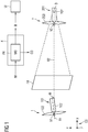
- FIG. 1 is a schematic illustration of a wind farm comprising a controller for performing an embodiment of the invention.
- Fig. 1 shows in the lower part a section of a wind farm comprising a first wind turbine 1 and a second wind turbine 2.
- the wind farm has more than those two wind turbines.
- the method described herein is applied to the wind turbines 1 and 2. Nevertheless, the method may also be applied to other pairs of wind turbines being part of the wind farm.
- a 3D coordinate system CS for indicating the spatial arrangement of the wind turbines is part of Fig. 1 .
- the vertical direction is indicated by the z-axis of the coordinate system CS whereas the directions parallel to the horizontal direction are indicated by the x-axis and y-axis of the coordinate system CS.
- the wind direction is along the x-axis of the coordinate system CS.
- Wind turbine 1 which is an upstream turbine with respect to the wind direction comprises an upper section 101 being located on top of a tower (not shown) which extends in the vertical z-direction.
- the upper section comprises a nacelle 102 accommodating an electric generator for generating electricity.
- the upper section 101 comprises a rotor 103 having three rotor blades with an angle of 120° therebetween where Fig. 1 only shows two of those blades.
- the rotor 103 is rotated around the horizontal rotor axis R1 by wind resulting in the generation of electricity by the generator within the nacelle 102.
- the upper section 101 of the turbine 1 can be pivoted around the vertical yaw axis V1.
- Wind turbine 2 which is located downstream with respect to the wind direction has the same construction as wind turbine 1.
- wind turbine 2 comprises an upper section 201 located at the top of a vertical tower, the upper section 201 comprising a nacelle 202 accommodating a generator as well as a rotor 203 attached to the nacelle 202. Due to the rotation of the rotor by wind around the horizontal rotor axis R2, electricity is generated by the generator within the nacelle 202.
- turbine 2 can be pivoted around a vertical yaw axis V2.
- the yaw angles of the upper sections 101 and 201 around the respective yaw axes V1 and V2 are adjusted such that the rotor axes R1 and R2 correspond to the wind direction measured by respective wind sensors installed at both wind turbines 1 and 2.
- a yaw misalignment may occur.
- This yaw misalignment is indicated by the yaw misalignment angle ⁇ in Fig. 1 .
- This angle is the obtuse angle between the rotor axis R1 of the wind turbine 1 and the rotor axis R2 of the wind turbine 2.
- the downstream wind turbine 2 comprises a camera 3 installed on the nacelle 201.
- the camera 3 is positioned such that it takes images IM of the rear side of the wind turbine 1.
- the camera is working in the visible light spectrum and also in the infrared light spectrum so that the method as described herein may also be performed at night.
- the respective images IM of the camera 3 are transferred by a suitable communication link to a controller 4 of the wind farm.
- the controller comprises a processor PR implementing a trained data driven model MO receiving a respective image IM as a digital input and providing a yaw misalignment angle ⁇ as a digital output.
- the trained data driven model MO is based on a Convolutional Neural Network having being learned beforehand by training data.
- the training data comprise a plurality of images of an upstream turbine taken by the camera of a downstream turbine together with the information of the yaw misalignment angle occurring in the respective image.
- Convolutional Neural Networks are well known from the prior art and are particularly suitable for processing digital images.
- a Convolutional Neural Network comprises convolutional layers followed by pooling layers as well as fully connected layers in order to determine at least one property of the respective image where the property according to the invention is the yaw misalignment angle.
- the yaw misalignment angle ⁇ produced as an output of the model MO results in an output on a user interface UI which is only shown schematically.
- the user interface UI comprises a display.
- the user interface provides information for a human operator.
- the output based on the yaw misalignment angle may be the angle itself so that the operator is informed about the misalignment.
- the output may be a warning in case that the yaw misalignment angle exceeds a predetermined threshold.
- the yaw misalignment angle ⁇ determined by the model MO also results in control commands CO which are provided to the wind turbines 1 and 2 in order to adjust the yaw angles of the turbines.
- the control commands are such that the wind turbines 1 and 2 are rotated in opposite directions around their respective yaw axis V1 and V2 by an angle which is half of the yaw misalignment angle so that the yaw misalignment angle will become zero.
- the controller 4 enables an automatic adjustment of the yaw angles to eliminate yaw misalignment between the wind turbines 1 and 2 resulting in a significantly reduced loss of generated electric power produced by the wind farm.
- the invention as described in the foregoing has several advantages. Particularly, an easy and straightforward method in order to detect yaw misalignments between adjacent turbines is provided. To do so, the yaw misalignment is determined based on images of a camera via a suitably trained data driven model. In a preferred embodiment, the yaw angles of the wind turbines are also automatically controlled based on the yaw misalignment determined by the data driven model in order to reduce electric power losses.
Landscapes
- Engineering & Computer Science (AREA)
- General Engineering & Computer Science (AREA)
- Sustainable Energy (AREA)
- Chemical & Material Sciences (AREA)
- Combustion & Propulsion (AREA)
- Sustainable Development (AREA)
- Life Sciences & Earth Sciences (AREA)
- Mechanical Engineering (AREA)
- Theoretical Computer Science (AREA)
- Computer Vision & Pattern Recognition (AREA)
- General Physics & Mathematics (AREA)
- Physics & Mathematics (AREA)
- Quality & Reliability (AREA)
- Artificial Intelligence (AREA)
- Evolutionary Computation (AREA)
- Wind Motors (AREA)
Priority Applications (5)
| Application Number | Priority Date | Filing Date | Title |
|---|---|---|---|
| EP19188519.3A EP3770426A1 (de) | 2019-07-26 | 2019-07-26 | Verfahren und vorrichtung zur computerimplementierten überwachung einer oder mehrerer windturbinen in einem windpark |
| CN202080053925.6A CN114144581A (zh) | 2019-07-26 | 2020-04-23 | 用于风电场中的一个或多个风力涡轮机的计算机实现的监视的方法和装置 |
| US17/628,652 US11821404B2 (en) | 2019-07-26 | 2020-04-23 | Method and an apparatus for computer-implemented monitoring of one or more wind turbines in a wind farm |
| PCT/EP2020/061401 WO2021018424A1 (en) | 2019-07-26 | 2020-04-23 | A method and an apparatus for computer-implemented monitoring of one or more wind turbines in a wind farm |
| EP20725426.9A EP3959438B1 (de) | 2019-07-26 | 2020-04-23 | Verfahren und vorrichtung zur computerimplementierten überwachung einer oder mehrerer windturbinen in einem windpark |
Applications Claiming Priority (1)
| Application Number | Priority Date | Filing Date | Title |
|---|---|---|---|
| EP19188519.3A EP3770426A1 (de) | 2019-07-26 | 2019-07-26 | Verfahren und vorrichtung zur computerimplementierten überwachung einer oder mehrerer windturbinen in einem windpark |
Publications (1)
| Publication Number | Publication Date |
|---|---|
| EP3770426A1 true EP3770426A1 (de) | 2021-01-27 |
Family
ID=67439032
Family Applications (2)
| Application Number | Title | Priority Date | Filing Date |
|---|---|---|---|
| EP19188519.3A Pending EP3770426A1 (de) | 2019-07-26 | 2019-07-26 | Verfahren und vorrichtung zur computerimplementierten überwachung einer oder mehrerer windturbinen in einem windpark |
| EP20725426.9A Active EP3959438B1 (de) | 2019-07-26 | 2020-04-23 | Verfahren und vorrichtung zur computerimplementierten überwachung einer oder mehrerer windturbinen in einem windpark |
Family Applications After (1)
| Application Number | Title | Priority Date | Filing Date |
|---|---|---|---|
| EP20725426.9A Active EP3959438B1 (de) | 2019-07-26 | 2020-04-23 | Verfahren und vorrichtung zur computerimplementierten überwachung einer oder mehrerer windturbinen in einem windpark |
Country Status (4)
| Country | Link |
|---|---|
| US (1) | US11821404B2 (de) |
| EP (2) | EP3770426A1 (de) |
| CN (1) | CN114144581A (de) |
| WO (1) | WO2021018424A1 (de) |
Families Citing this family (2)
| Publication number | Priority date | Publication date | Assignee | Title |
|---|---|---|---|---|
| EP4067648A1 (de) * | 2021-04-01 | 2022-10-05 | Siemens Gamesa Renewable Energy A/S | Verfahren zur abbildung eines windturbinenrotorblattes |
| CN113324548B (zh) * | 2021-05-27 | 2022-04-12 | 南京韦博智控科技有限公司 | 一种风力发电机叶片巡检路径的规划方法 |
Citations (4)
| Publication number | Priority date | Publication date | Assignee | Title |
|---|---|---|---|---|
| EP2940295A1 (de) * | 2014-04-29 | 2015-11-04 | General Electric Company | System und verfahren zur steuerung einer windenergieanlage |
| EP3023636A1 (de) * | 2014-11-24 | 2016-05-25 | General Electric Company | Systeme und verfahren zur optimierung des betriebs eines windparks |
| US20190072082A1 (en) * | 2016-03-14 | 2019-03-07 | Ventus Engineering GmbH | Method of condition monitoring one or more wind turbines and parts thereof and performing instant alarm when needed |
| GB2568676A (en) * | 2017-11-21 | 2019-05-29 | Equinor Asa | Wind turbine blade orientation detection |
Family Cites Families (9)
| Publication number | Priority date | Publication date | Assignee | Title |
|---|---|---|---|---|
| WO2009129617A1 (en) * | 2008-04-24 | 2009-10-29 | Mike Jeffrey | A method and system for determining an imbalance of a wind turbine rotor |
| BRPI0822913A2 (pt) * | 2008-10-09 | 2015-06-23 | Mitsubishi Heavy Ind Ltd | Gerador de turbina de vento fora da costa e fazenda de vento fora da costa |
| DE102011088447A1 (de) * | 2011-12-13 | 2013-06-13 | Robert Hörmann | Inspektion von Windrädern in Windparks |
| US9512820B2 (en) * | 2013-02-19 | 2016-12-06 | Siemens Aktiengesellschaft | Method and system for improving wind farm power production efficiency |
| ES2769353T3 (es) * | 2013-05-20 | 2020-06-25 | Principle Power Inc | Sistema y procedimiento para controlar plataformas de aerogeneradores flotantes marinos |
| US9551322B2 (en) * | 2014-04-29 | 2017-01-24 | General Electric Company | Systems and methods for optimizing operation of a wind farm |
| US10138873B2 (en) * | 2014-05-30 | 2018-11-27 | General Electric Company | Systems and methods for wind turbine nacelle-position recalibration and wind direction estimation |
| CN104481804B (zh) * | 2014-12-05 | 2017-02-22 | 北京金风科创风电设备有限公司 | 风力发电机组对风矫正控制方法、装置和系统 |
| DE102015007441A1 (de) * | 2015-06-15 | 2016-12-15 | Senvion Gmbh | Verfahren und Computerprogrammprodukt zur Überprüfung der Ausrichtung von Windenergieanlagen, sowie Anordnung aus wenigstens zwei Windenergieanlagen |
-
2019
- 2019-07-26 EP EP19188519.3A patent/EP3770426A1/de active Pending
-
2020
- 2020-04-23 CN CN202080053925.6A patent/CN114144581A/zh active Pending
- 2020-04-23 US US17/628,652 patent/US11821404B2/en active Active
- 2020-04-23 EP EP20725426.9A patent/EP3959438B1/de active Active
- 2020-04-23 WO PCT/EP2020/061401 patent/WO2021018424A1/en not_active Ceased
Patent Citations (4)
| Publication number | Priority date | Publication date | Assignee | Title |
|---|---|---|---|---|
| EP2940295A1 (de) * | 2014-04-29 | 2015-11-04 | General Electric Company | System und verfahren zur steuerung einer windenergieanlage |
| EP3023636A1 (de) * | 2014-11-24 | 2016-05-25 | General Electric Company | Systeme und verfahren zur optimierung des betriebs eines windparks |
| US20190072082A1 (en) * | 2016-03-14 | 2019-03-07 | Ventus Engineering GmbH | Method of condition monitoring one or more wind turbines and parts thereof and performing instant alarm when needed |
| GB2568676A (en) * | 2017-11-21 | 2019-05-29 | Equinor Asa | Wind turbine blade orientation detection |
Also Published As
| Publication number | Publication date |
|---|---|
| EP3959438A1 (de) | 2022-03-02 |
| WO2021018424A1 (en) | 2021-02-04 |
| EP3959438B1 (de) | 2024-05-29 |
| US11821404B2 (en) | 2023-11-21 |
| CN114144581A (zh) | 2022-03-04 |
| US20220275787A1 (en) | 2022-09-01 |
Similar Documents
| Publication | Publication Date | Title |
|---|---|---|
| US9982656B2 (en) | Method, device, and system for controlling wind alignment correction of wind turbine generator system | |
| CN109154274B (zh) | 对风力涡轮机进行监测并在需要时执行警报的方法 | |
| EP3959438B1 (de) | Verfahren und vorrichtung zur computerimplementierten überwachung einer oder mehrerer windturbinen in einem windpark | |
| AU2020399503A1 (en) | Method and apparatus for detecting yaw-to-wind abnormality, and device and storage medium thereof | |
| US20170241409A1 (en) | Verification of wind turbine nacelle yaw position sensor | |
| EP3771822A1 (de) | Verfahren zur computerimplementierten bestimmung eines senkrechten windprofils eines windfeldes | |
| DK179188B1 (en) | Wind turbine and a method of operating a wind turbine | |
| EP2631471A1 (de) | Windpark | |
| CN206127108U (zh) | 溢流法玻璃生产线及其自动控制系统 | |
| EP3907402A1 (de) | Verfahren und vorrichtung zur computerimplementierten überwachung einer windturbine | |
| CN105610087B (zh) | 电网输电线巡视系统 | |
| CN105516685A (zh) | 电力电网输电线巡视方法 | |
| CN102797631A (zh) | 一种风电机组的最优增益在线自校正方法、系统及其装置 | |
| CN110778454A (zh) | 一种风电机组协调控制方法和系统 | |
| EP4045791A1 (de) | Verfahren und vorrichtung zum computerimplementierten überwachen einer windturbine | |
| US12293558B2 (en) | Meter recognition apparatus, meter monitoring system, and monitoring method therefor | |
| US12006913B2 (en) | Method and an apparatus for computer-implemented monitoring of one or more wind turbines in a wind farm | |
| CN118654572B (zh) | 用于集热器托架的空间位置检测方法及系统 | |
| EP3682519B1 (de) | Verbesserungen im zusammenhang mit der spannungsregelung in windkraftanlagen | |
| CN118188345A (zh) | 一种风电场实时监控系统及方法 | |
| CN117175556A (zh) | 一种光伏电力供应管理系统 | |
| CN116591901A (zh) | 一种风电机组变桨控制方法及系统 | |
| EP4097351A1 (de) | Verfahren zur computerimplementierten steuerung einer oder mehrerer windturbinen in einem windpark | |
| CN113883009A (zh) | 一种风力发电机组测风仪角度自优化方法 | |
| US9954366B2 (en) | Grid power factor control system |
Legal Events
| Date | Code | Title | Description |
|---|---|---|---|
| PUAI | Public reference made under article 153(3) epc to a published international application that has entered the european phase |
Free format text: ORIGINAL CODE: 0009012 |
|
| STAA | Information on the status of an ep patent application or granted ep patent |
Free format text: STATUS: THE APPLICATION HAS BEEN PUBLISHED |
|
| AK | Designated contracting states |
Kind code of ref document: A1 Designated state(s): AL AT BE BG CH CY CZ DE DK EE ES FI FR GB GR HR HU IE IS IT LI LT LU LV MC MK MT NL NO PL PT RO RS SE SI SK SM TR |