EP3770431A1 - Hydraulische druckmittelversorgungsanordnung und verfahren - Google Patents
Hydraulische druckmittelversorgungsanordnung und verfahren Download PDFInfo
- Publication number
- EP3770431A1 EP3770431A1 EP20186948.4A EP20186948A EP3770431A1 EP 3770431 A1 EP3770431 A1 EP 3770431A1 EP 20186948 A EP20186948 A EP 20186948A EP 3770431 A1 EP3770431 A1 EP 3770431A1
- Authority
- EP
- European Patent Office
- Prior art keywords
- variable
- actual
- control
- controller
- pressure medium
- Prior art date
- Legal status (The legal status is an assumption and is not a legal conclusion. Google has not performed a legal analysis and makes no representation as to the accuracy of the status listed.)
- Granted
Links
Images



Classifications
-
- F—MECHANICAL ENGINEERING; LIGHTING; HEATING; WEAPONS; BLASTING
- F04—POSITIVE - DISPLACEMENT MACHINES FOR LIQUIDS; PUMPS FOR LIQUIDS OR ELASTIC FLUIDS
- F04B—POSITIVE-DISPLACEMENT MACHINES FOR LIQUIDS; PUMPS
- F04B49/00—Control, e.g. of pump delivery, or pump pressure of, or safety measures for, machines, pumps, or pumping installations, not otherwise provided for, or of interest apart from, groups F04B1/00 - F04B47/00
- F04B49/002—Hydraulic systems to change the pump delivery
-
- F—MECHANICAL ENGINEERING; LIGHTING; HEATING; WEAPONS; BLASTING
- F15—FLUID-PRESSURE ACTUATORS; HYDRAULICS OR PNEUMATICS IN GENERAL
- F15B—SYSTEMS ACTING BY MEANS OF FLUIDS IN GENERAL; FLUID-PRESSURE ACTUATORS, e.g. SERVOMOTORS; DETAILS OF FLUID-PRESSURE SYSTEMS, NOT OTHERWISE PROVIDED FOR
- F15B21/00—Common features of fluid actuator systems; Fluid-pressure actuator systems or details thereof, not covered by any other group of this subclass
- F15B21/08—Servomotor systems incorporating electrically operated control means
- F15B21/087—Control strategy, e.g. with block diagram
-
- F—MECHANICAL ENGINEERING; LIGHTING; HEATING; WEAPONS; BLASTING
- F03—MACHINES OR ENGINES FOR LIQUIDS; WIND, SPRING, OR WEIGHT MOTORS; PRODUCING MECHANICAL POWER OR A REACTIVE PROPULSIVE THRUST, NOT OTHERWISE PROVIDED FOR
- F03C—POSITIVE-DISPLACEMENT ENGINES DRIVEN BY LIQUIDS
- F03C1/00—Reciprocating-piston liquid engines
- F03C1/02—Reciprocating-piston liquid engines with multiple-cylinders, characterised by the number or arrangement of cylinders
- F03C1/06—Reciprocating-piston liquid engines with multiple-cylinders, characterised by the number or arrangement of cylinders with cylinder axes generally coaxial with, or parallel or inclined to, main shaft axis
- F03C1/0678—Control
- F03C1/0686—Control by changing the inclination of the swash plate
-
- F—MECHANICAL ENGINEERING; LIGHTING; HEATING; WEAPONS; BLASTING
- F04—POSITIVE - DISPLACEMENT MACHINES FOR LIQUIDS; PUMPS FOR LIQUIDS OR ELASTIC FLUIDS
- F04B—POSITIVE-DISPLACEMENT MACHINES FOR LIQUIDS; PUMPS
- F04B1/00—Multi-cylinder machines or pumps characterised by number or arrangement of cylinders
- F04B1/12—Multi-cylinder machines or pumps characterised by number or arrangement of cylinders having cylinder axes coaxial with, or parallel or inclined to, main shaft axis
- F04B1/26—Control
- F04B1/28—Control of machines or pumps with stationary cylinders
- F04B1/29—Control of machines or pumps with stationary cylinders by varying the relative positions of a swash plate and a cylinder block
- F04B1/295—Control of machines or pumps with stationary cylinders by varying the relative positions of a swash plate and a cylinder block by changing the inclination of the swash plate
-
- F—MECHANICAL ENGINEERING; LIGHTING; HEATING; WEAPONS; BLASTING
- F04—POSITIVE - DISPLACEMENT MACHINES FOR LIQUIDS; PUMPS FOR LIQUIDS OR ELASTIC FLUIDS
- F04B—POSITIVE-DISPLACEMENT MACHINES FOR LIQUIDS; PUMPS
- F04B1/00—Multi-cylinder machines or pumps characterised by number or arrangement of cylinders
- F04B1/12—Multi-cylinder machines or pumps characterised by number or arrangement of cylinders having cylinder axes coaxial with, or parallel or inclined to, main shaft axis
- F04B1/26—Control
- F04B1/30—Control of machines or pumps with rotary cylinder blocks
- F04B1/32—Control of machines or pumps with rotary cylinder blocks by varying the relative positions of a swash plate and a cylinder block
- F04B1/324—Control of machines or pumps with rotary cylinder blocks by varying the relative positions of a swash plate and a cylinder block by changing the inclination of the swash plate
-
- F—MECHANICAL ENGINEERING; LIGHTING; HEATING; WEAPONS; BLASTING
- F04—POSITIVE - DISPLACEMENT MACHINES FOR LIQUIDS; PUMPS FOR LIQUIDS OR ELASTIC FLUIDS
- F04B—POSITIVE-DISPLACEMENT MACHINES FOR LIQUIDS; PUMPS
- F04B49/00—Control, e.g. of pump delivery, or pump pressure of, or safety measures for, machines, pumps, or pumping installations, not otherwise provided for, or of interest apart from, groups F04B1/00 - F04B47/00
- F04B49/06—Control using electricity
-
- F—MECHANICAL ENGINEERING; LIGHTING; HEATING; WEAPONS; BLASTING
- F04—POSITIVE - DISPLACEMENT MACHINES FOR LIQUIDS; PUMPS FOR LIQUIDS OR ELASTIC FLUIDS
- F04B—POSITIVE-DISPLACEMENT MACHINES FOR LIQUIDS; PUMPS
- F04B49/00—Control, e.g. of pump delivery, or pump pressure of, or safety measures for, machines, pumps, or pumping installations, not otherwise provided for, or of interest apart from, groups F04B1/00 - F04B47/00
- F04B49/08—Regulating by delivery pressure
-
- F—MECHANICAL ENGINEERING; LIGHTING; HEATING; WEAPONS; BLASTING
- F04—POSITIVE - DISPLACEMENT MACHINES FOR LIQUIDS; PUMPS FOR LIQUIDS OR ELASTIC FLUIDS
- F04B—POSITIVE-DISPLACEMENT MACHINES FOR LIQUIDS; PUMPS
- F04B49/00—Control, e.g. of pump delivery, or pump pressure of, or safety measures for, machines, pumps, or pumping installations, not otherwise provided for, or of interest apart from, groups F04B1/00 - F04B47/00
- F04B49/22—Control, e.g. of pump delivery, or pump pressure of, or safety measures for, machines, pumps, or pumping installations, not otherwise provided for, or of interest apart from, groups F04B1/00 - F04B47/00 by means of valves
-
- F—MECHANICAL ENGINEERING; LIGHTING; HEATING; WEAPONS; BLASTING
- F15—FLUID-PRESSURE ACTUATORS; HYDRAULICS OR PNEUMATICS IN GENERAL
- F15B—SYSTEMS ACTING BY MEANS OF FLUIDS IN GENERAL; FLUID-PRESSURE ACTUATORS, e.g. SERVOMOTORS; DETAILS OF FLUID-PRESSURE SYSTEMS, NOT OTHERWISE PROVIDED FOR
- F15B21/00—Common features of fluid actuator systems; Fluid-pressure actuator systems or details thereof, not covered by any other group of this subclass
- F15B21/08—Servomotor systems incorporating electrically operated control means
-
- F—MECHANICAL ENGINEERING; LIGHTING; HEATING; WEAPONS; BLASTING
- F04—POSITIVE - DISPLACEMENT MACHINES FOR LIQUIDS; PUMPS FOR LIQUIDS OR ELASTIC FLUIDS
- F04B—POSITIVE-DISPLACEMENT MACHINES FOR LIQUIDS; PUMPS
- F04B2201/00—Pump parameters
- F04B2201/12—Parameters of driving or driven means
- F04B2201/1201—Rotational speed of the axis
-
- F—MECHANICAL ENGINEERING; LIGHTING; HEATING; WEAPONS; BLASTING
- F04—POSITIVE - DISPLACEMENT MACHINES FOR LIQUIDS; PUMPS FOR LIQUIDS OR ELASTIC FLUIDS
- F04B—POSITIVE-DISPLACEMENT MACHINES FOR LIQUIDS; PUMPS
- F04B2201/00—Pump parameters
- F04B2201/12—Parameters of driving or driven means
- F04B2201/1205—Position of a non-rotating inclined plate
- F04B2201/12051—Angular position
-
- F—MECHANICAL ENGINEERING; LIGHTING; HEATING; WEAPONS; BLASTING
- F04—POSITIVE - DISPLACEMENT MACHINES FOR LIQUIDS; PUMPS FOR LIQUIDS OR ELASTIC FLUIDS
- F04B—POSITIVE-DISPLACEMENT MACHINES FOR LIQUIDS; PUMPS
- F04B2203/00—Motor parameters
- F04B2203/06—Motor parameters of internal combustion engines
- F04B2203/0603—Torque
-
- F—MECHANICAL ENGINEERING; LIGHTING; HEATING; WEAPONS; BLASTING
- F04—POSITIVE - DISPLACEMENT MACHINES FOR LIQUIDS; PUMPS FOR LIQUIDS OR ELASTIC FLUIDS
- F04B—POSITIVE-DISPLACEMENT MACHINES FOR LIQUIDS; PUMPS
- F04B2205/00—Fluid parameters
- F04B2205/05—Pressure after the pump outlet
-
- F—MECHANICAL ENGINEERING; LIGHTING; HEATING; WEAPONS; BLASTING
- F04—POSITIVE - DISPLACEMENT MACHINES FOR LIQUIDS; PUMPS FOR LIQUIDS OR ELASTIC FLUIDS
- F04B—POSITIVE-DISPLACEMENT MACHINES FOR LIQUIDS; PUMPS
- F04B2205/00—Fluid parameters
- F04B2205/09—Flow through the pump
Definitions
- the invention relates to a hydraulic pressure medium supply arrangement for a hydraulic circuit, for example for mobile work machines, according to the preamble of claim 1. Furthermore, the invention relates to a method for a hydraulic pressure medium supply arrangement.
- a pressure and flow rate control system is known from the document RE 30630 / 04.13 from Rexroth. This is used for the electrohydraulic control of a swivel angle, a pressure and a power of an axial piston variable displacement pump.
- the control system has an axial piston variable displacement pump with an electrically controlled proportional valve.
- An actuating piston can be controlled via this. This is used to adjust a swash plate of the variable displacement pump.
- a displacement transducer is provided for the actuating piston, via which a swivel angle of the swash plate can be determined on the basis of the displacement path of the actuating piston.
- a swivel angle of the swash plate on the swivel axis can also be tapped using a Hall sensor.
- the volume flow of the variable displacement pump can in turn be determined from the swivel angle of the swashplate.
- the variable displacement pump is driven by a motor. If the variable displacement pump is not driven and the actuating system is depressurized, the variable displacement pump swivels to a maximum delivery volume by the force of a spring. When the variable displacement pump is driven and the pilot valve is de-energized and the pump outlet is closed, the variable displacement pump swivels to a zero stroke pressure.
- a equilibrium between the pump pressure on the setting piston and the spring force of the spring is established at around 4 to 8 bar.
- the basic setting is usually taken when the control electronics are dead.
- a control for the pilot valve has a setpoint pressure, a setpoint swivel angle and optionally a setpoint power value as input variable.
- An actual pressure on the output side of the variable displacement pump is recorded by a pressure sensor. As explained above, an actual swivel angle is determined via the displacement transducer. The actual values recorded are processed in an amplifier and compared with the specified target values.
- a minimum value generator then ensures that only the controller assigned to the desired operating point is automatically active. An output signal from the minimum value generator is then a setpoint value for a proportional magnet on the pilot valve.
- a displacement path of a valve slide of the pilot valve is recorded via a displacement sensor and reported to the controller.
- the document RD 30242 / 03.10 from Rexroth discloses external control electronics for the described adjustment of the axial piston adjusting machine. Furthermore, in the document RD 92 088 / 08.04 from Rexroth, an electro-hydraulic control system is disclosed.
- a pivotable hydraulic axial piston adjusting machine is provided, which is connected to another hydraulic machine via a drive shaft. Furthermore, a control loop for a drive torque of the adjusting machine is provided. An actual drive torque and a setpoint drive torque are fed to the control loop, from which a manipulated variable for an adjusting device of the variable displacement machine is determined.
- the target drive torque is an output variable of a minimum value generator. This selects an output variable for a pressure control and a volume flow control.
- the volume flow of the hydraulic machine connected to the adjusting machine is provided as the actual volume flow. Furthermore, a high pressure of this hydraulic machine is provided as the actual pressure.
- EP 2 851 565 B1 , U.S. 4,801,247 , U.S. 5,182,908 , EP 034 9092 B1 , US 5267441 , US 5967756 and US 5170625 each discloses a hydraulic machine with a swivel angle sensor and a pressure sensor.
- the pressure, the volume flow and the output can be controlled.
- the invention is based on the object of creating a hydraulic pressure medium supply arrangement which can be regulated in a simple manner and / or in which vibrations are reduced or even prevented during operation. Furthermore, the invention is based on the object of creating a simple method for the hydraulic pressure medium supply arrangement which leads to an improvement in the actuating behavior.
- a hydraulic pressure medium supply arrangement for an open hydraulic circuit, which is used in particular for mobile work machines.
- the pressure medium supply arrangement can have a hydraulic machine, the delivery volume or stroke volume of which can be adjusted via an adjusting mechanism.
- the hydraulic machine is an axial piston machine with a swivel cradle or adjustable swash plate or an axial piston machine of bent axis design.
- the adjusting mechanism preferably has an adjusting cylinder with an adjusting piston for adjusting the delivery volume or stroke volume of the hydraulic machine.
- the adjusting mechanism preferably has an electrically proportional controllable pilot valve. This can be used to control an inflow and / or an outflow into a control chamber of the actuating cylinder that is delimited by the actuating piston.
- the pressure medium supply arrangement can have an electronic control for the pilot valve.
- This preferably has a controller with an output variable in the form of a manipulated variable for the pilot valve, in particular for an actuator of the pilot valve.
- the valve slide of the pilot valve assumes a middle position at a certain neutral current, in particular for its actuator, or at a certain control signal. In the middle position it is advantageously provided that the actuating piston does not perform any movement, which means that the hydraulic machine or hydraulic machine is in a steady state the pressure medium supply arrangement can be present.
- a pilot control variable for the neutral current is preferably linked to the manipulated variable on the output side or at the output of the controller. This is used to pre-control the neutral current.
- a pre-control variable for the neutral current is linked to the manipulated variable of the controller in order to set the manipulated variable for the pilot valve.
- This solution has the advantage that the controller only has to output the "net signal” for adjusting the swivel angle or the delivery volume for the hydraulic machine.
- a control signal or the neutral current for the middle position of the valve slide is specified and therefore the control output does not have to undergo any change without affecting the control system. It has also been shown that this significantly improves the vibration behavior of the pressure medium supply arrangement. In normal operation, there are no or comparatively low vibrations in the pressure medium supply arrangement. An exact pilot control of the neutral flow is also advantageous in order to achieve the required dynamics of the pressure medium supply arrangement.
- the controller has a control element for the pilot control variable that determines the pilot control variable based on a characteristic map.
- the pilot control variable can then be determined via the characteristics map as a function of an operating state of the pressure medium supply arrangement. It is then conceivable that at least one state variable or actual variable of the pressure medium supply arrangement is provided as the input variable for the control element.
- the characteristics map and / or the pilot control variable can be adapted or corrected.
- the positions of the valve slide, for example the middle position, of the pilot valve can change with the same current supply, in particular over the period of use after the pressure medium supply arrangement has been started up.
- the change is usually dependent on various parameters, including age and wear.
- the neutral current adapted to changing conditions. For example, it is conceivable that the neutral current is first measured when the pressure medium supply is started up and then adapted or corrected if necessary.
- the adaptation of the characteristic diagram and / or the pilot control variable is advantageous because the neutral current varies depending on the operating state of the pressure medium supply arrangement (actual output pressure, actual temperature, actual speed) and is subject to fluctuations, in particular due to aging and manufacturing tolerances of the valve slide of the pilot valve , the magnet and the spring.
- a one-dimensional or multi-dimensional characteristic diagram is provided as the characteristic diagram, for example.
- the map can be designed as a neutral current curve.
- An actual output pressure and / or an actual rotational speed and / or an actual swivel angle of the hydraulic machine and / or an actual temperature of a pressure medium of the hydraulic machine are conceivable as dimension (s) for the characteristic map. If, for example, the actual output pressure is provided as the dimension, the neutral current can then be taken from the characteristic diagram as a function of this pressure.
- the controller is provided for regulating an actual delivery volume adjustment speed or for regulating an actual swivel angle adjustment speed of the hydraulic machine.
- the actual delivery volume adjustment speed or actual swivel angle adjustment speed in particular as a derivation of the actual delivery volume or the actual swivel angle, and a target delivery volume adjustment speed or target swivel angle adjustment speed of the hydraulic machine can be provided as the input variable.
- the manipulated variable for the pilot valve can serve as the output variable.
- the controller that regulates the delivery volume adjustment speed or the swivel angle adjustment speed can pre-control the neutral current at the output so that the controller only has to output the net signal for adjusting the swivel angle or delivery volume of the hydraulic machine.
- the controller for the actual delivery volume adjustment speed or the actual swivel angle adjustment speed of the hydraulic machine is designed, for example, as a PI controller. If the map were not adapted, a deviation of the map or neutral current map from the actual neutral current would be compensated for by the I component in the controller or in the inner swivel angle control loop. Indeed such a raised I-component leads to overshoots in the control. Thus, by means of the adaptation, an exact pre-control of the neutral current can advantageously take place with the smallest possible I-component, which leads to an extremely advantageous dynamic reaction of the hydraulic machine and to little overshoot. The reason is that the I component is no longer suitable if the operating point changes, e.g. the actual swivel angle or the actual output pressure, and thus a dead path / dead time would arise in the controller output until the I component is adapted .
- This solution has the advantage that the characteristic map for the neutral current can be updated or adapted automatically.
- the I component can be kept small and the control behavior of the hydraulic machine can be improved. All deviations and tolerances can then be automatically compensated.
- the adaptation of the pilot control variable and / or the characteristic diagram is preferably carried out in such a way that, in the steady-state operating state, the manipulated variable is zero or essentially zero in a central position of the valve slide of the pilot valve.
- the manipulated variable deviates from zero in the steady operating state and is therefore controlled as an error value for the neutral current, the manipulated variable as an error value with the pre-control variable and / or is offset against the map.
- the pilot control variable and / or the characteristic diagram can thus be adapted in a simple manner by viewing the manipulated variable as an error value in the steady-state operating state.
- a subtraction of the manipulated variable as an error value from the pilot control variable and / or the characteristic map is provided for offsetting.
- the manipulated variable can be subtracted as an error value from a support point of the characteristic diagram, in particular in the form of the neutral current curve.
- that point of the characteristic diagram that has the smallest distance from the steady-state operating state is selected as the support point. It would also be conceivable to take into account the closest support points, weighted depending on their distance from the operating state.
- the pump status or the hydraulic machine status is detected first.
- a stationary working point can be determined and then its position in the map.
- a neutral current is then determined from the nominal characteristic map or the previously valid characteristic map.
- a new map or a new value can then be transferred to the feedforward control.
- An evaluation of the machine status can thus initially be provided in that working points or stationary points are determined. Subsequently, an assignment of the working point or the working points to a support point or to several support points in the characteristic diagram can be provided.
- the characteristic diagram is first updated and then a new characteristic diagram is output.
- the adaptation takes place when a steady operating state is present, for example when the actual swivel angle and the actual output pressure of the hydraulic machine are constant.
- a steady-state operating state can be identified in which the derivative of the swivel angle is zero or less than a defined value.
- the signal component then controlled by the controller or the PI control element as an error in relation to the neutral current is then subtracted as an error from the neutral current curve or from the characteristic diagram.
- the error is subtracted from the base point of the neutral current curve, which corresponds to the steady-state operating state. In this way, for example, the map can be shifted.
- a characteristic curve of a pump that has a hydromechanical EP controller is adapted here.
- a specific valve control signal then results in a specific swivel angle. This can be precontrolled in an electronic control unit by means of a characteristic curve. This characteristic is adapted again and again during operation.
- a hydraulic pressure medium supply arrangement with a hydraulic machine which has an adjustable swash plate is disclosed.
- An angle of the swash plate can be adjusted using a pilot valve.
- the pilot valve can be activated via a controller. If the pilot valve is activated with a neutral current, a valve slide of the pilot valve assumes a middle position in which the swash plate does not move.
- the controller outputs a manipulated variable. On the output side of the control, the manipulated variable is linked to a pre-control variable for the neutral current and adapted to pre-control the neutral current.
- a hydraulic pressure medium supply arrangement 1 which has a hydraulic machine in the form of an axial piston machine 2.
- This has a swivel cradle for adjusting a delivery volume.
- the axial piston machine 2 can be used both as a pump and as a motor.
- the axial piston machine 2 is driven via a drive unit 4, which can be, for example, an internal combustion engine, such as a diesel unit, or an electric motor.
- the axial piston machine 2 is connected to the drive unit 4 via a drive shaft 6.
- a speed 8 of the drive shaft 6 can be tapped via means not shown, for example via a speed sensor, and fed to a control of the pressure medium supply arrangement 1.
- An adjusting mechanism 12 is provided for the axial piston machine 2. This has a pilot valve 14.
- valve slide can be controlled electrically proportionally via an actuator 16.
- a control variable 18 is fed to the actuator 16 by a controller 20.
- the valve slide of the pilot valve 14 is acted upon by a spring force of a valve spring 22 in the direction of a basic position. The spring force acts against the actuator force of the actuator 16.
- the output side of the axial piston machine 2 is connected to a pressure line 24, which in turn is connected to a main control valve 26 or valve block. This can be used to control the pressure medium supply between the axial piston machine 2 and one or more consumers.
- a control line 28 branches off from the pressure line 24 and is connected to a pressure connection P of the pilot valve 14.
- the control line 28 is formed, for example, in a housing of the axial piston machine 2.
- the pilot valve 14 also has a tank connection T which is connected to a tank via a tank line 30.
- the pilot valve 14 has a working connection A, which is connected to a control chamber 32 of an actuating cylinder 34.
- the control chamber 32 is delimited by an actuating piston 36 of the actuating cylinder.
- a swash plate of the axial piston machine 2 can then be adjusted via the adjusting piston 36.
- a displacement path of the actuating piston 36 is detected via a displacement transducer 38.
- a swivel angle of the swivel cradle of the axial piston machine 2 is tapped from a swivel axis of the swivel cradle via a rotary, magnetic sensor.
- the actual delivery volume or the actual displacement volume of the axial piston machine 2 can then be determined via the detected path.
- the actual delivery volume 40 is then reported to the controller 20.
- the pressure connection P is connected to the working connection A and the tank connection T is blocked.
- valve slide When charged of the valve slide with the actuator force of the actuator 16, the valve slide is moved, starting from its basic position, in the direction of switching positions in which the pressure connection P is blocked and the working connection A is connected to the tank connection T.
- pressure medium from the pressure line 24 is applied to the actuating piston 36.
- a cylinder 42 is provided in the adjustment mechanism 12. This has an actuating piston 44 which engages the swash plate of the axial piston machine 2.
- the actuating piston 44 delimits a control chamber 46 which is connected to the pressure line 24.
- the actuating piston 44 is acted upon by pressure medium of the control chamber 46 and by the spring force of a spring 48 in such a way that it loads the swash plate in the direction of increasing the delivery volume.
- a pressure sensor 50 is provided, via which the pressure in the pressure line 24 is tapped and reported to the controller 20, the pressure being an actual output pressure 52.
- a pressure sensor 54 is provided, which detects the highest actual load pressure (actual LS pressure) 56 that is transmitted to controller 20.
- a controller 57 is connected to the controller 20 via a CAN interface 58 in order to set in particular the actual speed and one or more control setpoints, such as the setpoint output pressure, the setpoint delivery volume or the setpoint swivel angle, setpoint power or the setpoint torque to be transmitted to the controller 20. It is also conceivable to feed the actual speed 8 directly to the controller 20.
- the position of the swash plate of the axial piston machine 2 is controlled via the pilot valve 14 and the actuating piston 36.
- a conveyed volume flow of the axial piston machine 2 is proportional to the position of the swash plate.
- the adjusting piston 44 or counter-piston, which is pretensioned by the spring 48, is constantly subjected to the actual output pressure or pump pressure.
- the swash plate is held in a position +100 percent by the spring 48.
- the swash plate swivels to a zero stroke pressure, since the actuating piston 36 is acted upon by pressure medium from the pressure line 24.
- a balance between an actual output pressure at the actuating piston 36 and the spring force of the spring 48 is established in a a predetermined pressure or pressure range, for example between 8 to 12 bar.
- This zero-stroke operation is assumed, for example, in the case of de-energized electronics or control 20.
- the control of the pilot valve 14 takes place via the controller 20, which is, for example, preferably digital electronics, or alternatively analog electronics.
- the controller 20 processes the required control signals, which is explained in more detail below.
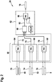
- Fig. 2 shows schematically a mode of operation of the controller 20.
- This has a first control circuit 60 and a second control circuit 62.
- the first control circuit 60 has a controller 64 for a swivel angle of the swash plate of the axial piston machine 2 Fig. 1 , a regulator 66 for the output pressure of the axial piston machine 2 and a regulator 68 for a torque of the axial piston machine 2.
- the controller 64 has a setpoint delivery volume 70 and the actual delivery volume 40 as input variables.
- a manipulated variable 72 is provided as the output variable.
- the controller 66 has a setpoint output pressure 74 and the actual output pressure 52 as input variables.
- a manipulated variable 75 is provided as the output variable.
- the controller 68 has an actual torque 76 or a setpoint torque as input variables.
- the actual torque is provided as a further input variable, which in turn can be determined, for example, on the basis of a characteristic map of the actual speed 8 and / or the actual output pressure and / or the actual pivot angle or the actual delivery volume.
- a manipulated variable 78 is provided as the output variable for the controller 68.
- the input variables are each fed to a control element in the form of a PID controller.
- the manipulated variables 72, 75 and 78 are fed to a minimum value generator 80. This ensures that only the controller 72, 75 or 78 assigned to the desired operating point is automatically active. In this case, either the output pressure, the torque or the delivery volume is precisely regulated, the other two variables in each case being below a predetermined setpoint.
- An output signal of the minimum value generator 80 is then a setpoint in the form of a delivery volume adjustment speed or a set delivery volume adjustment speed 82 or a set swivel angle adjustment speed.
- This is then an input variable for the second subordinate control loop 62.
- a further input variable of the second control loop 62 is the derivation of the actual delivery volume 40, which is then an actual delivery volume adjustment speed 84.
- the input variables 82 and 84 for the second control loop 62 is then fed to a control element in the form of a PID element 86. This then outputs the manipulated variable 18 for the pilot valve 14 Fig. 1 out.
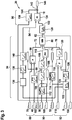
- Fig. 3 is another embodiment for the controller 20 from Fig. 1 shown.
- This has a regulator 88 for the delivery volume of the axial piston machine 2, see also Fig. 1 .
- a regulator 90 for the output pressure of the axial piston machine 2 and a regulator 92 for the torque of the axial piston machine 2 are provided.
- This is part of a first control loop 94.
- a second control loop 96, which is subordinate to the first control loop, is provided for the delivery volume adjustment speed or the swivel angle adjustment speed of the axial piston machine 2.
- the controller 88 has a control element 98 in the form of a P element.
- the target delivery volume 70 and the actual delivery volume 40 are provided as input variables.
- the actual delivery volume 40 is supplied with the regulating element 98 via a filter in the form of a PT1 filter.
- the manipulated variable 72 is provided as an output variable which is fed to the minimum value generator 80.
- the controller 90 has the actual output pressure 52, the actual LS pressure 56, a target pressure difference 100 and a target pressure gradient 102 as input variables.
- the actual LS pressure 56 and the desired pressure difference 100 are linked via a summing element 104 to form a desired output pressure.
- the target output pressure is then fed to a control element 106 in the form of an inverted PT1 element, which estimates a probable signal profile.
- the target output pressure is then fed to a control element 108, which has the target pressure gradient 102 as a further input variable.
- the setpoint pressure gradient 102 specifies the maximum possible gradient that should be provided.
- the setpoint output pressure is then influenced by the predefined setpoint pressure gradient 102 via the control element 108 in such a way that the dynamics of the pressure medium supply arrangement 1 start with the setpoint pressure gradient 102 Fig. 1 is controllable.
- the influencing can be such that the higher the setpoint pressure gradient 102, the faster the swash plate of the axial piston machine 2 can be adjusted. Conversely, the smaller the target pressure gradient, the slower the swash plate of the axial piston machine 2 is adjusted.
- the setpoint output pressure is then fed to a control element 110 in the form of a PID element.
- a further input variable for control element 110 is then the actual output pressure 52 is provided.
- the manipulated variable 75 which is fed to the minimum value generator 80, results as the output variable of the control element 110.
- the actual LS pressure 56 of the regulator 90 is fed to a filter 112, which is a variable PT1 filter, before the summing element 104.
- the filters 112 and 114 have variable, in particular pressure-dependent, filter coefficients.
- the controller 92 has the actual speed 8, the actual delivery volume 40, the actual output pressure 52 and a target torque 116 as input variables.
- the input variables are fed to a control element 118 in the form of a P element.
- the manipulated variable 78 which is fed to the minimum value generator 80, is provided as the output variable for the control element 118.
- a control element 120 is provided for the manipulated variable 78, which, like the control element 106, is an inverted PT1 filter.
- the actual speed, the actual delivery volume 40 and the actual output pressure 8 are fed to a control element 122 before being fed to the control element 118. This is used to calculate an actual torque 124 based on the actual speed 8, on the actual delivery volume 40 and the actual output pressure 8.
- the calculation is carried out using a map of the control element 122.
- the map is dependent on the actual output pressure 52 , which is fed to the control element 122.
- the actual delivery volume 40 is fed to the control element 122.
- the characteristic map can then alternatively or additionally depend on the actual delivery volume 40.
- the actual torque 124 is formed from the actual speed 8 and from the actual output pressure 52 and / or from the actual delivery volume 40.
- the actual torque 124 is then fed to a filter 126 in the form of a PT1 element before it reaches the regulating element 118.
- the actual delivery volume 40 is fed to a filter 99 in the form of a PT1 element before it is fed to the regulating element 98.
- the minimum value generator 80 forms the setpoint delivery volume adjustment speed 82 or setpoint swivel angle adjustment speed from the manipulated variables 72, 75 and 78. This is fed to a control element 128.
- the dynamics of the pressure medium supply arrangement 1 can be influenced with this. This is as Another input variable for the control element 128 is a setpoint delivery volume adjustment speed 130 or a setpoint swivel angle adjustment speed which is adjustable.
- the setpoint delivery volume adjustment speed 82 or setpoint swivel angle adjustment speed output from the minimum value generator 80 can be limited and / or influenced in such a way that the higher the size 130 , the faster the swash plate of the axial piston machine 2 can be pivoted and vice versa.
- the dynamics of the pressure medium supply arrangement 1 can thus be influenced by adjusting the setpoint delivery volume adjusting speed 130 and / or by adjusting the setpoint pressure gradient 102.
- the pressure medium supply arrangement 1 can hereby be adapted in a simple and inexpensive manner to different work machines and / or to different conditions of use and / or to different purposes.
- the target delivery volume adjustment speed 132 or the target swivel angle adjustment speed is fed to the second control circuit 96 as an input variable.
- This has a control element 134 in the form of a PI element.
- the actual delivery volume adjustment speed 84 or the actual swivel angle adjustment speed is provided as a further input variable for the control element 134. This is based on the actual delivery volume 40, which is derived in a control element 136.
- the derivation that is to say the actual delivery volume adjustment speed, is then fed to a filter 138 in the form of a PT1 filter.
- a control element 140 in the form of an inverted PT1 filter is then provided before the actual variable 84 is fed to the control element 134.
- the control element 134 of the second control circuit 96 has the manipulated variable 18 for the pilot valve 14 as an output variable Fig. 1 on. This is fed to a summing element 142.
- a precontrol value 144 is provided as a further input variable for the summing element 142. This is an output variable of a control element 150, which has the actual output pressure 52 as an input variable.
- the pilot control value 144 is then determined on the basis of the actual output pressure 52.
- the summing element 142 then combines the manipulated variable 18 and the precontrol value 144, with which a neutral current is precontrolled in the steady-state operating state of the pilot valve. There is thus a pressure-dependent specification of a neutral signal value for the pilot valve 14 Fig. 1 . This has the advantage that the controller 20 with regard to this control task is relieved.
- a final manipulated variable 146 for the pilot valve 14 is then provided as the output variable of the summing element 142.
- the pilot control value 144 can be determined, preferably based on a model, taking into account flow forces in the pilot valve 14 and / or a magnetic characteristic of the actuator 16 and / or a control edge characteristic of the valve slide of the pilot valve 14 and / or a spring stiffness of the valve spring 22.
- Fig. 4 shows schematically a control element 168. This can alternatively to the control element 150 from Fig. 3 be provided for the second control loop 96.
- the pre-control value or the pre-control variable 144 is provided as the output variable.
- the control element 168 can be activated and deactivated via a switch 170.
- the control element 168 has an input block 172, a characteristic diagram block 174 and an output block 176.
- a setpoint current 178 (see FIG. 146) can be used as the input variable for the input block 172 Fig. 3 ) if required.
- a target output pressure 180 (see 74 Fig. 2 ) be provided. This is for example according to the statements Fig. 3 or the target output pressure is determined in addition to control element 110, see FIG. Fig.
- the actual output pressure 52 is a further input variable for input block 172, see also Fig. 3 , intended.
- the filtered actual output pressure downstream of the filter 114 can be provided as a further input variable.
- the actual delivery volume 40 or the actual pivot angle can be provided as an input variable.
- the actual delivery volume adjustment speed 84 or the actual swivel angle adjustment speed can be provided as an input variable.
- the temperature 154 can also be used as an input variable.
- the stationary operating state is identified in the characteristic diagram block 174, in which the actual delivery volume adjustment speed 84 or actual -Swivel angle adjustment speed is zero. Furthermore, a current characteristic diagram and / or an initial characteristic diagram is stored in characteristic diagram block 174. It is determined whether the steady-state operating state or operating point is on the map. If the operating point is not on the characteristic diagram, a point on the characteristic diagram is selected which comes closest to the working point, this point then being a support point. If the operating point is on the map, then the working point is the base. If the operating point is at a distance from the map, then the map is updated accordingly so that the operating point is on the map again. On the basis of the updated characteristics map, the precontrol value 144 is determined in output block 176.
- the adaptation can take place in such a way that in a step 182, as explained above, the steady-state operating state of the pressure medium supply arrangement is via the controller 20, see FIG. Fig. 3 , is determined.
- the determination takes place in such a way that the actual delivery volume adjustment speed 84 or the actual swivel angle adjustment speed is zero.
- the signal component controlled in this case by the control element 134 as an error for the neutral current 144 or precontrol value 144 is then subtracted as an error from the map or the neutral current curve in step 184.
- the subtraction is made here from the base point of the neutral current curve, i.e. the point that corresponds to the stationary Corresponds to or is closest to the operating state.
- the map can be one-dimensional, for example an actual output pressure / neutral current map.
- a multi-dimensional map is also conceivable, for example with the actual output pressure, the actual temperature and the actual speed.
- Fig. 6 shows an example of a characteristic diagram in the form of a neutral current curve 186.
- the neutral current I is dependent on the actual output pressure p.
- the neutral current I increases as the actual output pressure p increases and vice versa. It would also be conceivable that the neutral current I decreases with an increasing actual output pressure p and vice versa.
Landscapes
- Engineering & Computer Science (AREA)
- Mechanical Engineering (AREA)
- General Engineering & Computer Science (AREA)
- Chemical & Material Sciences (AREA)
- Analytical Chemistry (AREA)
- Physics & Mathematics (AREA)
- Fluid Mechanics (AREA)
- Combustion & Propulsion (AREA)
- Reciprocating Pumps (AREA)
- Control Of Positive-Displacement Pumps (AREA)
- Fluid-Pressure Circuits (AREA)
Abstract
Description
- Die Erfindung betrifft eine hydraulische Druckmittelversorgungsanordnung für einen hydraulischen Kreis, beispielsweise für mobile Arbeitsmaschinen, gemäß dem Oberbegriff des Anspruchs 1. Des Weiteren betrifft die Erfindung ein Verfahren für eine hydraulische Druckmittelversorgungsanordnung.
- Aus dem Dokument RD 30630/04.13 der Firma Rexroth, ist ein Druck- und Förderstrom-Regelsystem bekannt. Dieses dient zur elektrohydraulischen Regelung eines Schwenkwinkels, eines Drucks und einer Leistung einer Axialkolben-Verstellpumpe. Das Regelsystem hat eine Axialkolben-Verstellpumpe mit einem elektrisch angesteuerten Proportionalventil. Über dieses kann ein Stellkolben angesteuert werden. Dieser dient zum Verstellen einer Schrägscheibe der Verstellpumpe. Für den Stellkolben ist ein Wegaufnehmer vorgesehen, über den anhand des Verschiebewegs des Stellkolbens ein Schwenkwinkel der Schrägscheibe bestimmbar ist. Alternativ zum Wegaufnehmer kann auch ein Schwenkwinkel der Schrägscheibe an der Schwenkachse über einen Hall-Sensor abgegriffen werden. Aus dem Schwenkwinkel der Schrägscheibe wiederum kann der Volumenstrom der Verstellpumpe ermittelt werden. Die Verstellpumpe wird über einen Motor angetrieben. Wird die Verstellpumpe nicht angetrieben, und ist das Stellsystem drucklos, dann schwenkt die Verstellpumpe durch eine Federkraft einer Feder auf ein maximales Fördervolumen. Im angetriebenen Zustand der Verstellpumpe und bei stromlosem Pilotventil und verschlossenem Pumpenausgang schwenkt die Verstellpumpe dagegen auf einen Nullhubdruck. Ein Gleichgewicht zwischen Pumpendruck am Stellkolben und Federkraft der Feder stellt sich bei etwa 4 bis 8 bar ein. Die Grundeinstellung wird üblicherweise bei spannungsloser Regelelektronik eingenommen. Eine Steuerung für das Pilotventil weist als Eingangsgröße einen Soll-Druck, einen Soll-Schwenkwinkel und optional einen Soll-Leistungswert auf. Ein Ist-Druck ausgangsseitig der Verstellpumpe wird durch einen Drucksensor erfasst. Wie vorstehend erläutert, wird ein Ist-Schwenkwinkel über den Wegaufnehmer ermittelt. Die aufgenommenen IstWerte werden in einem Verstärker verarbeitet und mit den vorgegebenen Sollwerten verglichen. Ein Minimalwertbildner sorgt dann dafür, dass automatisch nur der dem gewünschten Arbeitspunkt zugeordnete Regler aktiv ist. Ein Ausgangssignal des Minimalwertbildners ist dann ein Sollwert für einen Proportionalmagneten am Pilotventil. Zum Steuern des Pilotventils wird ein Verschiebeweg eines Ventilschiebers des Pilotventils über einen Wegaufnehmer erfasst und der Steuerung gemeldet. In dem Dokument RD 30242/03.10 der Firma Rexroth ist eine externe Ansteuerelektronik für die beschriebene Verstellung der Axialkolben-Verstellmaschine offenbart. Des Weiteren ist in dem Dokument RD 92 088/08.04 der Firma Rexroth ein elektro-hydraulisches Regelsystem offenbart.
- Aus der
EP 1 460 505 A2 ist eine ablösende Regelung eines Drucks und eines Förderstroms offenbart. Hierbei ist eine verschwenkbare hydraulische Axialkolben-Verstellmaschine vorgesehen, die über eine Triebwelle mit einer weiteren Hydromaschine verbunden ist. Des Weiteren ist ein Regelkreis für ein Antriebsdrehmoment der Verstellmaschine vorgesehen. Dem Regelkreis wird ein Ist-Antriebsdrehmoment und ein Soll-Antriebsdrehmoment zugeführt, woraus eine Stellgröße für eine Stelleinrichtung der Verstellmaschine ermittelt wird. Das Soll-Antriebsdrehmoment wiederum ist eine Ausgangsgröße eines Minimalwertbildners. Dieser wählt hierbei eine Ausgangsgröße einer Druckregelung und einer Volumenstromregelung aus. Als Ist-Volumenstrom ist hierbei der Volumenstrom der mit der Verstellmaschine verbundenen Hydromaschine vorgesehen. Des Weiteren ist als Ist-Druck ein Hochdruck dieser Hydromaschine vorgesehen. - Des Weiteren ist in den Dokumenten
EP 2 851 565 B1 ,US 4 801 247 ,US 5 182 908 ,EP 034 9092 B1 ,US 5267441 ,US 5967756 undUS 5170625 jeweils eine Hydromaschine mit einem Schwenkwinkelsensor und einem Drucksensor offenbart. - Es kann der Druck, der Volumenstrom und die Leistung gesteuert werden.
- Demgegenüber liegt der Erfindung die Aufgabe zugrunde, eine hydraulische Druckmittelversorgungsanordnung zu schaffen, die auf einfache Weise regelbar ist und/oder bei der Schwingungen im Betrieb vermindert oder sogar verhindert sind. Des Weiteren liegt der Erfindung die Aufgabe zugrunde, ein einfaches Verfahren für die hydraulische Druckmittelversorgungsanordnung zu schaffen, das zu einer Verbesserung des Stellverhaltens führt.
- Die Aufgabe hinsichtlich der Druckmittelversorgungsanordnung wird gelöst gemäß den Merkmalen des Anspruchs 1 und hinsichtlich der Verfahrens gemäß den Merkmalen des Anspruchs 7.
- Vorteilhafte Weiterbildungen der Erfindung sind Gegenstand der Unteransprüche.
- Erfindungsgemäß ist eine hydraulische Druckmittelversorgungsanordnung für einen offenen hydraulischen Kreis vorgesehen, die insbesondere für mobile Arbeitsmaschinen eingesetzt ist. Die Druckmittelversorgungsanordnung kann eine Hydromaschine aufweisen, deren Fördervolumen oder Hubvolumen über einen Verstellmechanismus verstellbar ist. Beispielsweise handelt es sich bei der Hydromaschine um eine Axialkolbenmaschine mit einer Schwenkwiege oder verstellbaren Schrägscheibe oder um eine Axialkolbenmaschine in Schrägachsenbauart. Der Verstellmechanismus hat vorzugsweise einen Stellzylinder mit einem Stellkolben zum Verstellen des Fördervolumens oder Hubvolumens der Hydromaschine. Des Weiteren hat der Verstellmechanismus vorzugsweise ein elektrisch proportional ansteuerbares Pilotventil. Über dieses kann ein Zufluss und/oder ein Abfluss in einen vom Stellkolben begrenzten Steuerraum des Stellzylinders steuerbar sein. Dies dient zum Ansteuern des Stellkolbens, indem dieser mit Druckmittel beaufschlagbar ist. Des Weiteren kann die Druckmittelversorgungsanordnung eine elektronische Steuerung für das Pilotventil aufweisen. Diese hat vorzugsweise einen Regler mit einer Ausgangsgröße in Form einer Stellgröße für das Pilotventil, insbesondere für einen Aktor des Pilotventils. Es kann vorgesehen sein, dass der Ventilschieber des Pilotventils bei einem bestimmten Neutralstrom, insbesondere für seinen Aktor, oder bei einem bestimmten Ansteuersignal eine mittlere Stellung einnimmt. Bei der mittleren Stellung ist vorteilhafter Weise vorgesehen, dass der Stellkolben keine Bewegung ausführt, womit ein stationärer Zustand der Hydromaschine oder der Druckmittelversorgungsanordnung vorliegen kann. Mit anderen Worten ist bei dem Pilotventil vorgesehen, dass bei einem bestimmten Ansteuersignal oder Neutralstrom der Ventilschieber eine mittlere Stellung einnimmt, bei der der damit angesteuerte Stellkolben der Hydromaschine keine Bewegung ausführt. Vorzugsweise ist ausgangsseitig oder am Ausgang des Reglers eine Vorsteuergröße für den Neutralstrom mit der Stellgröße verknüpft. Dies dient zur Vorsteuerung des Neutralstroms. Mit anderen Worten ist ausgangsseitig des Reglers eine Vorsteuergröße für den Neutralstrom mit der Stellgröße des Reglers verknüpft, um die Stellgröße für das Pilotventil einzustellen.
- Diese Lösung hat den Vorteil, dass der Regler nur das "Netto-Signal" für die Verstellung des Schwenkwinkels oder Fördervolumens für die Hydromaschine ausgeben muss. Ein Ansteuersignal bzw. der Neutralstrom für die Mittelstellung des Ventilschiebers ist vorgegeben und somit muss der Regelausgang keine Veränderung durchmachen, ohne dass sich eine Auswirkung auf die Regelstrecke ergibt. Es hat sich auch gezeigt, dass hierdurch ein Schwingungsverhalten der Druckmittelversorgungsanordnung deutlich verbessert ist. Im Regelbetrieb treten keine oder vergleichsweise geringe Schwingungen bei der Druckmittelversorgungsanordnung auf. Eine exakte Vorsteuerung des Neutralstroms ist des Weiteren vorteilhaft, um eine geforderte Dynamik der Druckmittelversorgungsanordnung zu erreichen.
- In weiterer Ausgestaltung der Erfindung kann vorgesehen sein, dass die Steuerung für die Vorsteuergröße ein Regelglied hat, das anhand eines Kennfelds die Vorsteuergröße ermittelt. Dies hat den Vorteil, dass beispielsweise die Vorsteuergröße dann abhängig von einem Betriebszustand der Druckmittelversorgungsanordnung über das Kennfeld ermittelt werden kann. Es ist dann denkbar, dass als Eingangsgröße für das Regelglied zumindest eine Zustandsgröße oder Ist-Größe der Druckmittelversorgungsanordnung vorgesehen ist.
- Bei einer weiteren bevorzugten Ausgestaltung der Erfindung kann vorgesehen sein, dass das Kennfeld und/oder die Vorsteuergröße adaptierbar oder korrigierbar ist. Dies ist äußerst vorteilhaft, da sich Stellungen des Ventilschiebers, beispielsweise die mittlere Stellung, des Pilotventils ändern können bei einer gleichen Bestromung, insbesondere über die Einsatzdauer nach einer Inbetriebnahme der Druckmittelversorgungsanordnung. Die Änderung ist üblicherweise abhängig von verschiedenen Parametern, unter anderem auch alters- und verschleißbedingt. Durch die Adaption kann der Neutralstrom an sich ändernde Bedingungen angepasst werden. So ist beispielsweise denkbar, dass der Neutralstrom bei Inbetriebnahme der Druckmittelversorgung zunächst eingemessen wird und dann bei Bedarf adaptiert oder korrigiert werden kann. Mit anderen Worten ist die Adaption des Kennfelds und/oder der Vorsteuergröße vorteilhaft, da der Neutralstrom abhängig vom Betriebszustand der Druckmittelversorgungsanordnung (Ist-Ausgangsdruck, Ist-Temperatur, Ist-Drehzahl) variiert und streuungsbehaftet ist, insbesondere durch Alterung und Fertigungstoleranzen des Ventilschiebers des Pilotventils, des Magneten und der Feder.
- Als Kennfeld ist beispielsweise ein eindimensionales oder mehrdimensionales Kennfeld vorgesehen. Beispielsweise kann das Kennfeld als Neutralstromkurve ausgebildet sein. Als Dimension/en für das Kennfeld ist denkbar ein Ist-Ausgangsdruck und/oder eine Ist-Drehzahl und/oder einen Ist-Schwenkwinkel der Hydromaschine und/oder eine Ist-Temperatur eines Druckmittels der Hydromaschine vorzusehen. Ist beispielsweise als Dimension der Ist-Ausgangsdruck vorgesehen, so kann dann abhängig von diesem Druck der Neutralstrom aus dem Kennfeld entnommen werden.
- In weiterer Ausgestaltung der Erfindung ist denkbar, dass der Regler zum Regeln einer Ist-Fördervolumen-Verstellgeschwindigkeit oder zum Regeln einer Ist-Schwenkwinkel-Verstellgeschwindigkeit der Hydromaschine vorgesehen ist. Als Eingangsgröße kann die Ist-Fördervolumen-Verstellgeschwindigkeit oder Ist-Schwenkwinkel-Verstellgeschwindigkeit, insbesondere als Ableitung des Ist-Fördervolumens oder des Ist-Schwenkwinkels, und eine Soll-Fördervolumen-Verstellgeschwindigkeit oder Soll-Schwenkwinkel-Verstellgeschwindigkeit der Hydromaschine vorgesehen sein. Als Ausgangsgröße kann die Stellgröße für das Pilotventil dienen. Mit der Vorsteuergröße kann der Regler, der die Fördervolumen-Verstellgeschwindigkeit oder Schwenkwinkel-Verstellgeschwindigkeit regelt, am Ausgang den Neutralstrom vorsteuern, damit der Regler nur das Netto-Signal für die Verstellung des Schwenkwinkels oder Fördervolumens der Hydromaschine ausgeben muss.
- Der Regler für die Ist-Fördervolumen-Verstellgeschwindigkeit oder Ist-Schwenkwinkel-Verstellgeschwindigkeit der Hydromaschine ist beispielsweise als PI-Regler ausgebildet. Würde keine Adaption des Kennfelds erfolgen, so würde eine Abweichung des Kennfelds oder Neutralstromkennfeldes zum tatsächlichen Neutralstrom durch den I-Anteil im Regler oder im inneren Schwenkwinkelregelkreis ausgeglichen werden. Allerdings führt ein derartig aufgezogener I-Anteil zu Überschwingern in der Regelung. Somit kann vorteilhafter Weise durch die Adaption eine genaue Vorsteuerung des Neutralstroms bei möglichst kleinem I-Anteil erfolgen, was zu einer äußerst vorteilhaften dynamischen Reaktion der Hydromaschine und zu wenig Überschwingern führt. Der Grund ist, dass der I-Anteil nicht mehr passend ist, wenn sich der Betriebspunkt verändert, also beispielsweise der Ist-Schwenkwinkel oder der Ist-Ausgangsdruck, und damit ein Totweg/Totzeit im Reglerausgang entstehen würde, bis der I-Anteil angepasst ist.
- Erfindungsgemäß ist ein Verfahren für eine hydraulische Druckmittelversorgungsanordnung gemäß einem oder mehreren der vorhergehenden Aspekte vorgesehen, wobei das Verfahren folgenden Schritt aufweist:
- Verknüpfung der Vorsteuergröße für den Neutralstrom mit der Stellgröße, um den Neutralstrom vorzusteuern.
- In weiterer Ausgestaltung des Verfahrens können folgende Schritte vorgesehen sein:
- Ermittlung eines stationären Betriebszustands oder eines Arbeitspunktes oder eines Ist-Zustands der Druckmittelversorgungsanordnung über die Steuerung.
- Adaption der Vorsteuergröße und/oder des Kennfelds auf Basis des stationären Betriebszustands. Insbesondere kann vorgesehen sein, dass die Adaption der Vorsteuergröße und/oder des Kennfelds auf Basis der Stellgröße erfolgt, die von der Steuerung beim stationären Betriebszustand ausgegeben wird.
- Diese Lösung hat den Vorteil, dass eine automatische Aktualisierung oder Adaption des Kennfelds für den Neutralstrom ermöglicht ist. Somit kann, falls ein PI-Regler eingesetzt ist, der I-Anteil klein gehalten werden und das Regelverhalten der Hydromaschine verbessert werden. Es können dann alle Streuungen und Toleranzen automatisch ausgeglichen werden.
- Vorzugsweise erfolgt die Adaption der Vorsteuergröße und/oder des Kennfelds derart, dass bei dem stationären Betriebszustand die Stellgröße in einer mittleren Stellung des Ventilschiebers des Pilotventils null ist oder im Wesentlichen null.
- In weiterer Ausgestaltung des Verfahrens kann vorgesehen sein, dass, falls die Stellgröße beim stationären Betriebszustand von null abweicht und somit als Fehlerwert zum Neutralstrom dazu gesteuert wird, die Stellgröße als Fehlerwert mit der Vorsteuergröße und/oder dem Kennfeld verrechnet wird. Somit kann auf einfache Weise die Vorsteuergröße und/oder das Kennfeld adaptiert werden, indem die Stellgröße beim stationären Betriebszustand als Fehlerwert angesehen wird. Als Verrechnung ist beispielsweise eine Subtraktion der Stellgröße als Fehlerwert von der Vorsteuergröße und/oder dem Kennfeld vorgesehen. Beispielsweise kann die Stellgröße als Fehlerwert von einem Stützpunkt des Kennfelds, insbesondere in Form der Neutralstromkurve, abgezogen werden. Als Stützpunkt wird beispielsweise derjenige Punkt des Kennfelds ausgewählt, der den geringsten Abstand zum stationären Betriebszustand aufweist. Denkbar wäre auch, die am nächsten liegenden Stützpunkte abhängig von ihrem Abstand vom Betriebszustand gewichtet zu berücksichtigen.
- Mit anderen Worten kann vorgesehen sein, dass zunächst eine Detektion des Pumpenzustands oder des Hydromaschinenzustands erfolgt. Es kann ein stationärer Arbeitspunkt ermittelt werden und dann dessen Position im Kennfeld. Im Anschluss erfolgt dann die Ermittlung eines Neutralstroms aus dem nominellen Kennfeld oder bisher geltenden Kennfeld. Im Anschluss kann dann ein neues Kennfeld oder ein neuer Wert in die Vorsteuerung übernommen werden. Somit kann zunächst eine Bewertung des Maschinenstatus vorgesehen sein, indem eine Ermittlung von Arbeitspunkten oder stationären Punkten erfolgt. Im Anschluss kann dann eine Zuordnung des Arbeitspunktes oder der Arbeitspunkte zu einem Stützpunkt oder zu mehreren Stützpunkten im Kennfeld vorgesehen sein. Beim Prozess der Werteveränderung des Kennfelds wird zunächst das Kennfeld aktualisiert und dann ein neues Kennfeld ausgegeben.
- Es ist denkbar, die Adaption des Kennfelds und/oder des Vorsteuerwerts regelmäßig und/oder kontinuierlich zu wiederholen. Insbesondere erfolgt die Adaption dann, wenn ein stationärer Betriebszustand vorliegt, beispielsweise, wenn der Ist-Schwenkwinkel und Ist-Ausgangsdruck der Hydromaschine konstant ist. Zur Adaption der Neutralstromkurve bzw. des Kennfelds kann ein stationärer Betriebszustand identifiziert werden, bei dem die Ableitung des Schwenkwinkels null oder kleiner als ein definierter Wert ist. Der dann vom Regler oder vom PI-Regelglied als Fehler zum Neutralstrom dazu gesteuerte Signalanteil wird dann als Fehler von der Neutralstromkurve oder vom Kennfeld abgezogen. Insbesondere wird der Fehler von dem Stützpunkt der Neutralstromkurve abgezogen, der dem stationären Betriebszustand entspricht. Es kann hierdurch das Kennfeld beispielsweise verschoben werden.
- Eine Adaption einer Kennlinie ist beispielsweise in der
DE 10 2014 225 147 offenbart. Darin wird eine Kennlinie einer Pumpe adaptiert, die einen hydromechanischen EP-Regler hat. Ein bestimmtes Ventilansteuersignal hat dann einen bestimmten Schwenkwinkel zur Folge. Dies kann in einem elektronischen Steuergerät mittels einer Kennlinie vorgesteuert werden. Diese Kennlinie wird hier beim laufenden Betrieb immer wieder adaptiert. - Offenbart ist eine hydraulische Druckmittelversorgungsanordnung mit einer Hydromaschine, die eine verstellbare Schrägscheibe aufweist. Ein Winkel der Schrägscheibe ist über ein Pilotventil verstellbar. Das Pilotventil ist über eine Steuerung ansteuerbar. Wird das Pilotventil mit einem Neutralstrom angesteuert, so nimmt ein Ventilschieber des Pilotventils eine mittlere Stellung ein, bei der die Schrägscheibe keine Bewegung ausführt. Zum Steuern des Pilotventils ist vorgesehen, dass die Steuerung eine Stellgröße ausgibt. Die Stellgröße wird dabei ausgangsseitig der Steuerung mit einer Vorsteuergröße für den Neutralstrom verknüpft und adaptiert, um den Neutralstrom vorzusteuern.
- Bevorzugte Ausführungsbeispiele der Erfindung werden im Folgenden anhand schematischer Zeichnungen näher erläutert. Es zeigen:
-
Fig. 1 in einer schematischen Darstellung eine hydraulische Druckmittelversorgungsanordnung gemäß einem ersten Ausführungsbeispiel, -
Fig. 2 in einer schematischen Darstellung eine Steuerung für die Druckmittelversorgungsanordnung ausFig. 1 , -
Fig. 3 in einer schematischen Darstellung eine Steuerung für die Druckmittelversorgungsanordnung ausFig. 1 gemäß einem weiteren Ausführungsbeispiel, -
Fig. 4 in einer schematischen Darstellung eine Adaption eines Kennfelds für einen Neutralstrom, -
Fig. 5 ein Ablaufdiagramm für ein Verfahren für die hydraulische Druckmittelversorgungsanordnung gemäß einem Ausführungsbeispiel und -
Fig. 6 schematisch ein Kennfeld für einen Neutralstrom, wobei auf der Abszisse ein Ist-Ausgangsdruck einer Hydromaschine und auf der Ordinate der Neutralstrom vorgesehen ist. - Gemäß
Fig. 1 ist eine hydraulische Druckmittelversorgungsanordnung 1 gezeigt, die eine Hydromaschine in Form einer Axialkolbenmaschine 2 aufweist. Diese weist eine Schwenkwiege zum Verstellen eines Fördervolumens auf. Die Axialkolbenmaschine 2 ist sowohl als Pumpe als auch als Motor einsetzbar. Angetrieben wird die Axialkolbenmaschine 2 über eine Antriebseinheit 4, bei der es sich beispielsweise um einen Verbrennungsmotor, wie beispielsweise ein Dieselaggregat, oder um einen Elektromotor handeln kann. Über eine Triebwelle 6 ist die Axialkolbenmaschine 2 mit der Antriebseinheit 4 verbunden. Eine Drehzahl 8 der Triebwelle 6 kann über nicht dargestellte Mittel, beispielsweise über einen Drehzahlsensor, abgegriffen werden und einer Steuerung der Druckmittelversorgungsanordnung 1 zugeführt werden. Für die Axialkolbenmaschine 2 ist ein Verstellmechanismus 12 vorgesehen. Dieser hat ein Pilotventil 14. Dessen Ventilschieber ist elektrisch proportional über einen Aktor 16 ansteuerbar. Hierfür wird dem Aktor 16 eine Stellgröße 18 von einer Steuerung 20 zugeführt. Der Ventilschieber des Pilotventils 14 in Richtung einer Grundstellung mit einer Federkraft einer Ventilfeder 22 beaufschlagt. Die Federkraft wirkt dabei entgegen der Aktorkraft des Aktors 16. - Die Axialkolbenmaschine 2 ist ausgangsseitig mit einer Druckleitung 24 verbunden, die wiederum mit einem Hauptsteuerventil 26 oder Ventilblock verbunden ist. Über dieses kann die Druckmittelversorgung zwischen der Axialkolbenmaschine 2 und einem oder mehreren Verbrauchern gesteuert werden. Von der Druckleitung 24 zweigt eine Steuerleitung 28 ab, die an einen Druckanschluss P des Pilotventils 14 angeschlossen ist. Die Steuerleitung 28 ist beispielsweise in einem Gehäuse der Axialkolbenmaschine 2 ausgebildet. Des Weiteren weist das Pilotventil 14 einen Tankanschluss T auf, der über eine Tankleitung 30 mit einem Tank verbunden ist. Außerdem hat das Pilotventil 14 einen Arbeitsanschluss A, der mit einem Steuerraum 32 eines Stellzylinders 34 verbunden ist. Der Steuerraum 32 wird dabei von einem Stellkolben 36 des Stellzylinders begrenzt. Über den Stellkolben 36 kann dann eine Schrägscheibe der Axialkolbenmaschine 2 verstellt werden. Ein Verschiebeweg des Stellkolbens 36 wird über einen Wegaufnehmer 38 erfasst. Alternativ oder zusätzlich wird ein Schwenkwinkel der Schwenkwiege der Axialkolbenmaschine 2 über einen rotatorischen, magnetischen Sensor von einer Schwenkachse der Schwenkwiege abgegriffen. Über den erfassten Weg kann dann das Ist-Fördervolumen oder das Ist-Verdrängungsvolumen der Axialkolbenmaschine 2 ermittelt werden. Das Ist-Fördervolumen 40 wird dann der Steuerung 20 gemeldet. In der Grundstellung des Ventilschiebers des Pilotventils 14 ist der Druckanschluss P mit dem Arbeitsanschluss A verbunden und der Tankanschluss T abgesperrt. Bei Beaufschlagung des Ventilschiebers mit der Aktorkraft des Aktors 16 wird der Ventilschiebers ausgehend von seiner Grundstellung in Richtung von Schaltstellungen bewegt, bei denen der Druckanschluss P gesperrt und der Arbeitsanschluss A mit dem Tankanschluss T verbunden ist. Somit wird in der Grundstellung des Ventilschiebers des Pilotventils 14 der Stellkolben 36 mit Druckmittel aus der Druckleitung 24 beaufschlagt. Des Weiteren ist bei dem Verstellmechanismus 12 ein Zylinder 42 vorgesehen. Dieser hat einen Stellkolben 44, der an der Schrägscheibe der Axialkolbenmaschine 2 angreift. Der Stellkolben 44 begrenzt einen Steuerraum 46, der mit der Druckleitung 24 verbunden ist. Über Druckmittel des Steuerraums 46 und über die Federkraft einer Feder 48 wird der Stellkolben 44 derart beaufschlagt, dass dieser die Schrägscheibe in Richtung einer Vergrößerung des Fördervolumens belastet.
- Des Weiteren ist ein Drucksensor 50 vorgesehen, über den der Druck in der Druckleitung 24 abgegriffen und der Steuerung 20 gemeldet wird, wobei es sich bei dem Druck um einen Ist-Ausgangsdruck 52 handelt. Außerdem ist ein Drucksensor 54 vorgesehen, der den höchsten Ist-Lastdruck (Ist-LS-Druck) 56 erfasst, der der Steuerung 20 übermittelt wird.
- Eine Steuerung 57 ist über ein CAN Interface 58 mit der Steuerung 20 verbunden, um insbesondere die Ist-Drehzahl und einen oder mehrere Regelsollwert/e, wie beispielsweise den Soll-Ausgangsdruck, das Soll-Fördervolumen oder den Soll-Schwenkwinkel, Soll-Leistung oder das Soll-Drehmoment, an die Steuerung 20 zu übermitteln. Denkbar ist auch, die Ist-Drehzahl 8 direkt der Steuerung 20 zuzuführen.
- Im Einsatz der Druckmittelversorgungsanordnung 1 wird über das Pilotventil 14 und den Stellkolben 36 die Position der Schrägscheibe der Axialkolbenmaschine 2 gesteuert. Ein geförderter Volumenstrom der Axialkolbenmaschine 2 ist proportional zur Stellung der Schrägscheibe. Der durch die Feder 48 vorgespannte Verstellkolben 44 oder Gegenkolben wird ständig mit dem Ist-Ausgangsdruck oder Pumpendruck beaufschlagt. Bei nichtdrehender Axialkolbenmaschine 2 und drucklosem Verstellmechanismus 12 wird die Schrägscheibe durch die Feder 48 in einer Position +100 Prozent gehalten. Bei angetriebener Axialkolbenmaschine 2 und stromlosem Aktor 16 des Pilotventils 14 schwenkt die Schrägscheibe auf einen Nullhubdruck, da der Stellkolben 36 mit Druckmittel der Druckleitung 24 beaufschlagt ist. Ein Gleichgewicht zwischen einem Ist-Ausgangsdruck am Stellkolben 36 und der Federkraft der Feder 48 stellt sich bei einem vorbestimmten Druck oder Druckbereich ein, beispielsweise zwischen 8 bis 12 bar. Dieser Nullhubbetrieb wird beispielsweise bei einer spannungslosen Elektronik oder Steuerung 20 eingenommen. Die Ansteuerung des Pilotventils 14 erfolgt über die Steuerung 20, bei der es sich beispielsweise um vorzugsweise eine digitale Elektronik, alternativ um eine analoge Elektronik, handelt. Die Steuerung 20 verarbeitet die benötigten Regelsignale, was untenstehend näher erläutert ist.
-
Fig. 2 zeigt schematisch eine Funktionsweise der Steuerung 20. Diese hat einen ersten Regelkreis 60 und einen zweiten Regelkreis 62. Der erste Regelkreis 60 weist einen Regler 64 für einen Schwenkwinkel der Schrägscheibe der Axialkolbenmaschine 2 ausFig. 1 , einen Regler 66 für den Ausgangsdruck der Axialkolbenmaschine 2 und einen Regler 68 für ein Drehmoment der Axialkolbenmaschine 2 auf. Der Regler 64 hat als Eingangsgrößen ein Soll-Fördervolumen 70 und das Ist-Fördervolumen 40. Als Ausgangsgröße ist eine Stellgröße 72 vorgesehen. Der Regler 66 weist als Eingangsgrößen einen Soll-Ausgangsdruck 74 und den Ist-Ausgangsdruck 52 auf. Als Ausgangsgröße ist eine Stellgröße 75 vorgesehen. Der Regler 68 weist als Eingangsgrößen eine Ist-Drehmoment 76 oder ein Soll-Drehmoment auf. Als weitere Eingangsgröße ist das Ist-Drehmoment vorgesehen, das wiederum beispielsweise anhand eines Kennfelds über die Ist-Drehzahl 8 und/oder über den Ist-Ausgangsdruck und/oder über den Ist-Schwenkwinkel oder Ist-Fördervolumen ermittelbar ist. Als Ausgangsgröße für den Regler 68 ist eine Stellgröße 78 vorgesehen. Bei dem jeweiligen Regler 64 bis 68 werden die Eingangsgrößen jeweils einem Regelglied in Form eines PID-Reglers zugeführt. - Die Stellgrößen 72, 75 und 78 werden einem Minimalwertbildner 80 zugeführt. Dieser sorgt dafür, dass automatisch nur der dem gewünschten Arbeitspunkt zugeordnete Regler 72, 75 oder 78 aktiv ist. Hierbei wird dann entweder der Ausgangsdruck, das Drehmoment oder das Fördervolumen exakt ausgeregelt, wobei die jeweils beiden anderen Größen unterhalb eines vorgegebenen Sollwertes liegen. Ein Ausgangssignal des Minimalwertbildners 80 ist dann ein Sollwert in Form einer Fördervolumen-Verstellgeschwindigkeit oder Soll-Fördervolumen-Verstellgeschwindigkeit 82 oder Soll-Schwenkwinkel-Verstellgeschwindigkeit. Diese ist dann eine Eingangsgröße für den zweiten unterlagerten Regelkreis 62. Eine weitere Eingangsgröße des zweiten Regelkreises 62 ist die Ableitung des Ist-Fördervolumens 40, womit es sich dann um eine Ist-Fördervolumen-Verstellgeschwindigkeit 84 handelt. Die Eingangsgrößen 82 und 84 für den zweiten Regelkreis 62 werden dann einem Regelglied in Form eines PID-Glieds 86 zugeführt. Dieses gibt dann die Stellgröße 18 für das Pilotventil 14 aus
Fig. 1 aus. - Gemäß
Fig. 3 ist eine weitere Ausführungsform für die Steuerung 20 ausFig. 1 gezeigt. Diese hat einen Regler 88 für das Fördervolumen der Axialkolbenmaschine 2, s. auchFig. 1 . Des Weiteren ist ein Regler 90 für den Ausgangsdruck der Axialkolbenmaschine 2 und ein Regler 92 für das Drehmoment der Axialkolbenmaschine 2 vorgesehen. Dies ist ein Teil eines ersten Regelkreises 94. Des Weiteren ist ein dem ersten Regelkreis unterlagerter zweiter Regelkreis 96 für die Fördervolumen-Verstellgeschwindigkeit oder Schwenkwinkel-Verstellgeschwindigkeit der Axialkolbenmaschine 2 vorgesehen. - Der Regler 88 weist ein Regelglied 98 in Form eines P-Glieds auf. Als Eingangsgröße sind das Soll-Fördervolumen 70 und das Ist-Fördervolumen 40 vorgesehen. Das Ist-Fördervolumen 40 wird mit dem Regelglied 98 über einen Filter in Form eines PT1-Filters zugeführt. Ausgangsseitig des Reglers 88 ist die Stellgröße 72 als Ausgangsgröße vorgesehen, die dem Minimalwertbildner 80 zugeführt wird.
- Der Regler 90 weist als Eingangsgrößen den Ist-Ausgangsdruck 52, den Ist-LS-Druck 56, eine Soll-Druckdifferenz 100 und einen Soll-Druckgradienten 102 auf. Der Ist-LS-Druck 56 und die Soll-Druckdifferenz 100 werden über ein Summierglied 104 zu einem Soll-Ausgangsdruck verknüpft. Der Soll-Ausgangsdruck wird dann einem Regelglied 106 in Form eines invertierten PT1-Glieds zugeführt, das einen voraussichtlichen Signalverlauf abschätzt. Der Soll-Ausgangsdruck wird dann weiter einem Regelglied 108 zugeführt, das als weitere Eingangsgröße den Soll-Druckgradienten 102 aufweist. Der Soll-Druckgradient 102 gibt dann den maximal möglichen Gradienten vor, der vorgesehen sein soll. Über das Regelglied 108 wird dann der Soll-Ausgangsdruck von dem vorgegebenen Soll-Druckgradienten 102 derart beeinflusst, dass mit dem Soll-Druckgradienten 102 die Dynamik der Druckmittelversorgungsanordnung 1 aus
Fig. 1 steuerbar ist. Beispielsweise kann die Beeinflussung derart sein, dass, je höher der Soll-Druckgradient 102 ist, desto schneller kann die Schrägscheibe der Axialkolbenmaschine 2 verstellt werden. Umgekehrt gilt dann, je kleiner der Soll-Druckgradient ist, desto langsamer wird die Schrägscheibe der Axialkolbenmaschine 2 verstellt. Nach dem Regelglied 108 wird dann der Soll-Ausgangsdruck einem Regelglied 110 in Form eines PID-Glieds zugeführt. Als weitere Eingangsgröße für das Regelglied 110 ist dann der Ist-Ausgangsdruck 52 vorgesehen. Als Ausgangsgröße des Regelglieds 110 ergibt sich die Stellgröße 75, die dem Minimalwertbildner 80 zugeführt wird. - Der Ist-LS-Druck 56 des Reglers 90 wird vor dem Summierglied 104 einem Filter 112 zugeführt, bei dem es sich um einen variablen PT1-Filter handelt. Das Gleiche gilt für den Ist-Ausgangsdruck, der vor dem Regelglied 110 ebenfalls einem Filter 114 in Form eines variablen PT1-Filters zugeführt wird. Die Filter 112 und 114 haben variable, insbesondere druckabhängige, Filterkoeffizienten.
- Der Regler 92 hat als Eingangsgrößen die Ist-Drehzahl 8, das Ist-Fördervolumen 40, den Ist-Ausgangsdruck 52 und ein Soll-Drehmoment 116. Die Eingangsgrößen werden einem Regelglied 118 in Form eines P-Glieds zugeführt. Als Ausgangsgröße für das Regelglied 118 ist die Stellgröße 78 vorgesehen, die dem Minimalwertbildner 80 zugeführt ist. Nach dem Regelglied 118 ist für die Stellgröße 78 ein Regelglied 120 vorgesehen, bei dem es sich wie bei dem Regelglied 106 um einen invertierten PT1-Filter handelt. Des Weiteren wird die Ist-Drehzahl, das Ist-Fördervolumen 40 und der Ist-Ausgangsdruck 8 vor Zuführung zum Regelglied 118 einem Regelglied 122 zugeführt. Dieses dient zur Berechnung eines Ist-Drehmoments 124 basierend auf der Ist-Drehzahl 8, auf dem Ist-Fördervolumen 40 und dem Ist-Ausgangsdruck 8. Die Berechnung erfolgt anhand eines Kennfelds des Regelglieds 122. Das Kennfeld ist abhängig von dem Ist-Ausgangsdruck 52, der dem Regelglied 122 zugeführt wird. Des Weiteren wird dem Regelglied 122 das Ist-Fördervolumen 40 zugeführt. Das Kennfeld kann dann alternativ oder zusätzlich vom Ist-Fördervolumen 40 abhängen. Mit anderen Worten wird das Ist-Drehmoment 124 aus der Ist-Drehzahl 8 und aus dem Ist-Ausgangsdruck 52 und/oder aus dem Ist-Fördervolumen 40 gebildet. Das Ist-Drehmoment 124 wird dann im Anschluss einem Filter 126 in Form eines PT1-Glieds zugeführt, bevor es zum Regelglied 118 gelangt.
- Des Weiteren wird das Ist-Fördervolumen 40, bevor es dem Regelglied 98 zugeführt wird, einem Filter 99 in Form eines PT1-Glieds zugeführt.
- Der Minimalwertbildner 80 bildet aus den Stellgrößen 72, 75 und 78 die Soll-Fördervolumen-Verstellgeschwindigkeit 82 oder Soll-Schwenkwinkel-Verstellgeschwindigkeit. Diese wird einem Regelglied 128 zugeführt. Mit diesem kann die Dynamik der Druckmittelversorgungsanordnung 1 beeinflusst werden. Hierfür ist als weitere Eingangsgröße für das Regelglied 128 eine Soll-Fördervolumen-Verstellgeschwindigkeit 130 oder Soll-Schwenkwinkel-Verstellgeschwindigkeit vorgesehen, die verstellbar ist. Beispielsweise ist mit der Soll-Fördervolumen-Verstellgeschwindigkeit 130 oder Soll-Schwenkwinkel-Verstellgeschwindigkeit, die aus dem Minimalwertbildner 80 ausgegebene Soll-Fördervolumen-Verstellgeschwindigkeit 82 oder Soll-Schwenkwinkel-Verstellgeschwindigkeit limitierbar und/oder derart beeinflussbar, dass, je höher die Größe 130 ist, desto schneller kann die Schrägscheibe der Axialkolbenmaschine 2 verschwenkt werden und umgekehrt. Somit kann die Dynamik der Druckmittelversorgungsanordnung 1 durch Verstellen der Soll-Fördervolumen-Verstellgeschwindigkeit 130 und/oder durch Verstellen des Soll-Druckgradienten 102 beeinflusst werden. Beispielsweise kann hierdurch die Druckmittelversorgungsanordnung 1 an unterschiedliche Arbeitsmaschinen und/oder an unterschiedliche Einsatzbedingungen und/oder an unterschiedliche Einsatzzwecke auf einfache und kostengünstige Weise angepasst werden.
- Nach dem Regelglied 128 wird die Soll-Fördervolumen-Verstellgeschwindigkeit 132 oder Soll-Schwenkwinkel-Verstellgeschwindigkeit dem zweiten Regelkreis 96 als Eingangsgröße zugeführt. Dieser hat ein Regelglied 134 in Form eines PI-Glieds. Als weitere Eingangsgröße für das Regelglied 134 ist die Ist-Fördervolumen-Verstellgeschwindigkeit 84 oder Ist-Schwenkwinkel-Verstellgeschwindigkeit vorgesehen. Diese basiert auf dem Ist-Fördervolumen 40, das in einem Regelglied 136 abgeleitet wird. Danach wird die Ableitung, also die Ist-Fördervolumen-Verstellgeschwindigkeit, einem Filter 138 in Form eines PT1-Filters zugeführt. Anschließend ist ein Regelglied 140 in Form eines invertierten PT1-Filters vorgesehen, bevor die Ist-Größe 84 dem Regelglied 134 zugeführt ist. Das Regelglied 134 des zweiten Regelkreises 96 weist als Ausgangsgröße die Stellgröße 18 für das Pilotventil 14 aus
Fig. 1 auf. Diese wird einem Summierglied 142 zugeführt. Als weitere Eingangsgröße für das Summierglied 142 ist ein Vorsteuerwert 144 vorgesehen. Bei diesem handelt es sich um eine Ausgangsgröße eines Regelglieds 150, das als Eingangsgröße den Ist-Ausgangsdruck 52 aufweist. Basierend auf dem Ist-Ausgangsdruck 52 wird dann der Vorsteuerwert 144 ermittelt. Das Summierglied 142 verknüpft dann die Stellgröße 18 und den Vorsteuerwert 144, womit ein Neutralstrom im stationären Betriebszustand des Pilotventils vorgesteuert ist. Es erfolgt damit eine druckabhängige Vorgabe eines Neutralsignalwertes für das Pilotventil 14 ausFig. 1 . Dies hat den Vorteil, dass die Steuerung 20 hinsichtlich dieser Steuerungsaufgabe entlastet wird. Als Ausgangsgröße des Summierglieds 142 ist dann eine endgültige Stellgröße 146 für das Pilotventil 14 vorgesehen. - Im Regelglied 150 kann der Vorsteuerwert 144 vorzugsweise modellbasiert unter Berücksichtigung von Strömungskräften beim Pilotventil 14 und/oder einem Magnetcharakteristikum des Aktors 16 und/oder einer Steuerkantencharakteristik des Ventilschiebers des Pilotventils 14 und/oder einer Federsteifigkeit der Ventilfeder 22 ermittelt sein.
-
Fig. 4 zeigt schematisch ein Regelglied 168. Dieses kann alternativ zu dem Regelglied 150 ausFig. 3 für den zweiten Regelkreis 96 vorgesehen sein. Als Ausgangsgröße ist der Vorsteuerwert oder die Vorsteuergröße 144 vorgesehen. Über einen Schalter 170 ist das Regelglied 168 aktivierbar und deaktivierbar. Das Regelglied 168 hat einen Eingangsblock 172, einen Kennfeldblock 174 und einen Ausgangsblock 176. Als Eingangsgröße für den Eingangsblock 172 kann ein Soll-Strom 178 (siehe 146Fig. 3 ) bei Bedarf vorgesehen sein. Des Weiteren kann als Eingangsgröße ein Soll-Ausgangsdruck 180 (siehe 74Fig. 2 ) vorgesehen sein. Dieser wird beispielsweise entsprechend den Ausführungen gemäßFig. 3 ermittelt oder der Soll-Ausgangsdruck wird zusätzlich zum Regelglied 110, s.Fig. 3 , dem Eingangsblock 172 zugeführt. Als weitere Eingangsgröße für den Eingangsblock 172 ist der Ist-Ausgangsdruck 52, s. auchFig. 3 , vorgesehen. Alternativ ist denkbar, den gefilterten Ist-Ausgangsdruck nach dem Filter 114 als Eingangsgröße zu verwenden. Als weitere Eingangsgröße kann das Soll-Fördervolumen 70 oder der Soll-Schwenkwinkel vorgesehen sein. Des Weiteren ist denkbar, als Eingangsgröße das Ist-Fördervolumen 40 oder den Ist-Schwenkwinkel zu verwenden. Außerdem kann die Ist-Fördervolumen-Verstellgeschwindigkeit 84 oder Ist-Schwenkwinkel-Verstellgeschwindigkeit als Eingangsgröße vorgesehen sein. Die Temperatur 154 ist ebenfalls als Eingangsgröße verwendbar. Anhand einer oder mehrerer der Eingangsgrößen, insbesondere anhand der Temperatur 154 und/oder anhand des Ist-Ausgangsdrucks 52 und/oder anhand des Ist-Fördervolumens 40 wird im Kennfeldblock 174 der stationäre Betriebszustand identifiziert, bei dem die Ist-Fördervolumen-Verstellgeschwindigkeit 84 oder Ist-Schwenkwinkel-Verstellgeschwindigkeit Null ist. Im Kennfeldblock 174 ist des Weiteren ein aktuelles Kennfeld und/oder ein initiales Kennfeld abgelegt. Es wird ermittelt, ob der stationäre Betriebszustand oder Arbeitspunkt auf dem Kennfeld liegt. Liegt der Arbeitspunkt nicht auf dem Kennfeld, so wird ein Punkt auf dem Kennfeld gewählt, der dem Arbeitspunkt am Nächsten kommt, wobei es sich bei diesem Punkt dann um einen Stützpunkt handelt. Liegt der Arbeitspunkt auf dem Kennfeld, dann ist der Arbeitspunkt der Stützpunkt. Ist der Arbeitspunkt vom Kennfeld beabstandet, dann wird das Kennfeld entsprechend aktualisiert, so dass der Arbeitspunkt wieder auf dem Kennfeld liegt. Anhand des aktualisierten Kennfelds wird beim Ausgangsblock 176 der Vorsteuerwert 144 ermittelt. - Gemäß
Fig. 5 kann die Adaption derart erfolgen, dass in einem Schritt 182, wie oben erläutert, der stationäre Betriebszustand der Druckmittelversorgungsanordnung über die Steuerung 20, s.Fig. 3 , ermittelt wird. Die Ermittlung erfolgt dabei derart, dass die Ist-Fördervolumen-Verstellgeschwindigkeit 84 oder Ist-Schwenkwinkel-Verstellgeschwindigkeit Null ist. Der in diesem Fall vom Regelglied 134 als Fehler zum Neutralstrom 144 oder Vorsteuerwert 144 dazu gesteuerte Signalanteil wird dann als Fehler von dem Kennfeld oder der Neutralstromkurve abgezogen in Schritt 184. Der Abzug erfolgt hierbei von dem Stützpunkt der Neutralstromkurve, also demjenigen Punkt, der dem stationären Betriebszustand entspricht oder diesem am Nächsten liegt. Das Kennfeld kann eindimensional sein, beispielsweise ein Ist-Ausgangsdruck-Neutralstrom-Kennfeld. Denkbar ist auch ein mehrdimensionales Kennfeld vorgesehen, beispielsweise mit dem Ist-Ausgangsdruck, der Ist-Temperatur und der Ist-Drehzahl. -
Fig. 6 zeigt beispielhaft ein Kennfeld in Form einer Neutralstromkurve 186. Der Neutralstrom I ist dabei abhängig vom Ist-Ausgangsdruck p. Der Neutralstrom I steigt hierbei bei steigendem Ist-Ausgangsdruck p und umgekehrt. Denkbar wäre auch, dass der Neutralstrom I bei einem steigenden Ist-Ausgangsdruck p sinkt und umgekehrt.
Claims (12)
- Hydraulische Druckmittelversorgungsanordnung für einen offenen hydraulischen Kreis, mit einer Hydromaschine (2), mit einem Verstellmechanismus (12), der einen Stellzylinder (34) mit einem Stellkolben (36) zum Verstellen des Fördervolumens der Hydromaschine (2) aufweist und der ein elektrisch proportional ansteuerbares Pilotventil (14) aufweist, wobei über das Pilotventil (14) ein Zufluss und/oder ein Abfluss in einem vom Stellkolben (36) begrenzten Steuerraum (32) des Stellzylinders (34) steuerbar ist, um den Stellkolben (36) zum Ansteuern mit Druckmittel zu beaufschlagen, und wobei eine elektronische Steuerung (20) für das Pilotventil (14) vorgesehen ist, die einen Regler (60, 62; 94, 96) mit einer Ausgangsgröße in Form einer Stellgröße (146) für das Pilotventil (14) hat, wobei ein Ventilschieber des Pilotventils (14) bei einem bestimmten Neutralstrom eine Stellung einnimmt, bei der vorgesehen ist, dass der Stellkolben (36) keine Bewegung ausführt, dadurch gekennzeichnet, dass ausgangsseitig des Reglers (60, 62; 94, 96) eine Vorsteuergröße (144) für den Neutralstrom mit der Stellgröße (146) des Reglers (60, 62; 94, 96) verknüpft ist, um die Stellgröße (146) für das Pilotventil (14) einzustellen.
- Druckmittelversorgungsanordnung nach Anspruch 1, wobei die Steuerung (20) für die Vorsteuergröße (144) ein Regelglied (150, 168) hat, das anhand eines Kennfelds die Vorsteuergröße (144) ermittelt.
- Druckmittelversorgungsanordnung nach Anspruch 2, wobei als Eingangsgröße für das Regelglied (150, 168) zumindest eine Betriebsgröße (40, 52, 70, 84, 154, 178, 180) der Druckmittelversorgungsanordnung (1) vorgesehen ist.
- Druckmittelversorgungsanordnung nach einem der vorhergehenden Ansprüche, wobei das Kennfeld und/oder die Vorsteuergröße (144) adaptierbar ist.
- Druckmittelversorgungsanordnung nach Anspruch 3 oder 4, wobei als Betriebsgröße ein Ist-Ausgangsdruck der Hydromaschine (2) und/oder eine Ist-Drehzahl (8) der Hydromaschine (2) und/oder eine Ist-Temperatur (154) eines Druckmittels und/oder ein Ist-Fördervolumen (40) der Hydromaschine (2) vorgesehen ist.
- Druckmittelversorgungsanordnung nach einem der vorhergehenden Ansprüche, wobei der Regler (134) zum Regeln einer Ist-Schwenkwinkel-Verstellgeschwindigkeit (84) der Hydromaschine (2) vorgesehen ist, der als Eingangsgröße eine Ist-Schwenkwinkel-Verstellgeschwindigkeit (84) und eine Soll-Schwenkwinkel-Verstellgeschwindigkeit (132) der Hydromaschine (2) aufweist und der als Ausgangsgröße die Stellgröße (18) des Reglers (60, 62; 94, 96) für das Pilotventil (14) aufweist.
- Verfahren für eine hydraulische Druckmittelversorgungsanordnung gemäß einem der vorhergehenden Ansprüche mit dem Schritt:- Verknüpfung der Vorsteuergröße (144) für den Neutralstrom mit der Stellgröße (18) des Reglers (60, 62; 94, 96), um die Stellgröße (146) für das Pilotventil (14) einzustellen.
- Verfahren nach Anspruch 7, wobei folgende Schritte vorgesehen sind:- Ermittlung eines stationären Betriebszustands der Druckmittelversorgungsanordnung über die Steuerung (20),- Adaption der Vorsteuergröße (144) und/oder des Kennfelds auf Basis des stationären Betriebszustands.
- Verfahren nach Anspruch 8, wobei die Adaption der Vorsteuergröße (144) und/oder des Kennfelds derart erfolgt, dass beim stationären Betriebszustand die Stellgröße (18) des Reglers (60, 62; 94, 96) in einer mittleren Stellung des Ventilschiebers des Pilotventils (14) Null ist.
- Verfahren nach Anspruch 8 oder 9, wobei bei dem stationären Betriebszustand die Ist-Schwenkwinkel-Verstellgeschwindigkeit (84) der Hydromaschine (2) Null ist.
- Verfahren nach einem der Ansprüche 8 bis 10, wobei, falls die Stellgröße (18) des Reglers (60, 62; 94, 96) beim stationären Betriebszustand von null abweicht und somit als Fehlerwert zum Neutralstrom dazu gesteuert wird, die Stellgröße (18) als Fehlerwert mit der Vorsteuergröße (144) und/oder mit dem Kennfeld derart verrechnet wird, dass hierdurch die Vorsteuergröße (144) und/oder das Kennfeld adaptiert oder aktualisiert wird.
- Verfahren nach Anspruch 11, wobei als Verrechnung eine Subtraktion der Stellgröße als Fehlerwert von der Vorsteuergröße (144) und/oder dem Kennfeld vorgesehen ist.
Applications Claiming Priority (2)
| Application Number | Priority Date | Filing Date | Title |
|---|---|---|---|
| DE102019120330 | 2019-07-26 | ||
| DE102019212845.9A DE102019212845A1 (de) | 2019-07-26 | 2019-08-27 | Hydraulische Druckmittelversorgungsanordnung und Verfahren |
Publications (2)
| Publication Number | Publication Date |
|---|---|
| EP3770431A1 true EP3770431A1 (de) | 2021-01-27 |
| EP3770431B1 EP3770431B1 (de) | 2022-05-04 |
Family
ID=74098919
Family Applications (1)
| Application Number | Title | Priority Date | Filing Date |
|---|---|---|---|
| EP20186948.4A Active EP3770431B1 (de) | 2019-07-26 | 2020-07-21 | Hydraulische druckmittelversorgungsanordnung und verfahren |
Country Status (5)
| Country | Link |
|---|---|
| US (1) | US20210025374A1 (de) |
| EP (1) | EP3770431B1 (de) |
| JP (1) | JP2021021393A (de) |
| CN (1) | CN112303066A (de) |
| DE (1) | DE102019212845A1 (de) |
Cited By (1)
| Publication number | Priority date | Publication date | Assignee | Title |
|---|---|---|---|---|
| DE102022201584A1 (de) | 2022-02-16 | 2023-08-17 | Robert Bosch Gesellschaft mit beschränkter Haftung | Ventilbaugruppe mit automatisch kalibrierbarer Stellungsregelung |
Families Citing this family (7)
| Publication number | Priority date | Publication date | Assignee | Title |
|---|---|---|---|---|
| DE102019219451A1 (de) * | 2019-07-26 | 2021-01-28 | Robert Bosch Gmbh | Hydraulische Druckmittelversorgungsanordnung für eine mobile Arbeitsmaschine und Verfahren |
| DE102021202739A1 (de) * | 2021-03-22 | 2022-09-22 | Robert Bosch Gesellschaft mit beschränkter Haftung | Hydraulische Druckmittelversorgungsanordnung, Verfahren mit einer hydraulischen Druckmittelversorgungsanordnung und mobile Arbeitsmaschine |
| DE102021205295B4 (de) | 2021-05-25 | 2024-10-10 | Robert Bosch Gesellschaft mit beschränkter Haftung | Verfahren zur Steuerung eines hydrostatischen Antriebs |
| DE102022200396B4 (de) * | 2022-01-14 | 2025-04-17 | Robert Bosch Gesellschaft mit beschränkter Haftung | Verfahren mit einer hydraulischen Druckmittelversorgungsanordnung und hydraulische Druckmittelversorgungsanordnung |
| DE102022202279B4 (de) * | 2022-03-07 | 2025-04-17 | Hawe Hydraulik Se | Elektrohydraulische Regelungsvorrichtung und verstellbares hydraulisches Pumpensystem |
| IT202200008888A1 (it) * | 2022-05-03 | 2023-11-03 | Bosch Gmbh Robert | Metodo di calibrazione del sistema di regolazione di una pompa idraulica |
| US12345203B2 (en) | 2023-06-12 | 2025-07-01 | Hamilton Sundstrand Corporation | Direct controlled variable displacement pump fuel systems with low pressure thermal recirculation pumping |
Citations (12)
| Publication number | Priority date | Publication date | Assignee | Title |
|---|---|---|---|---|
| US4801247A (en) | 1985-09-02 | 1989-01-31 | Yuken Kogyo Kabushiki Kaisha | Variable displacement piston pump |
| US5170625A (en) | 1989-07-27 | 1992-12-15 | Hitachi Construction Machinery Co., Ltd. | Control system for hydraulic pump |
| US5182908A (en) | 1992-01-13 | 1993-02-02 | Caterpillar Inc. | Control system for integrating a work attachment to a work vehicle |
| EP0349092B1 (de) | 1988-06-29 | 1993-02-24 | Hitachi Construction Machinery Co., Ltd. | Hydraulisches Antriebssystem |
| US5267441A (en) | 1992-01-13 | 1993-12-07 | Caterpillar Inc. | Method and apparatus for limiting the power output of a hydraulic system |
| US5967756A (en) | 1997-07-01 | 1999-10-19 | Caterpillar Inc. | Power management control system for a hydraulic work machine |
| EP1460505A2 (de) | 2003-03-21 | 2004-09-22 | Bosch Rexroth AG | Einrichtung zur ablösenden Regelung von Druck und Förderstrom eines hydraulischen Druckmittels |
| DE102013221625A1 (de) * | 2013-10-24 | 2015-04-30 | Robert Bosch Gmbh | Hydraulische Verstellvorrichtung mit Rückkopplung und hydrostatische verstellbare Axialkolbenmaschine in Schrägscheibenbauweise |
| DE102014225147A1 (de) | 2014-12-08 | 2016-06-09 | Robert Bosch Gmbh | Verfahren zur Identifikation einer Kennlinie |
| EP2851565B1 (de) | 2012-05-18 | 2017-01-04 | Doosan Corporation | Öldrucksteuersystem |
| DE102016222139A1 (de) * | 2016-11-11 | 2018-05-17 | Robert Bosch Gmbh | Verfahren zum Betreiben einer Axialkolbenmaschine in Schrägscheibenbauweise |
| DE102017000761A1 (de) * | 2017-01-27 | 2018-08-02 | Hydac Drive Center Gmbh | Versorgungsvorrichtung |
-
2019
- 2019-08-27 DE DE102019212845.9A patent/DE102019212845A1/de active Pending
-
2020
- 2020-07-21 EP EP20186948.4A patent/EP3770431B1/de active Active
- 2020-07-22 JP JP2020125374A patent/JP2021021393A/ja active Pending
- 2020-07-24 CN CN202010724464.2A patent/CN112303066A/zh active Pending
- 2020-07-24 US US16/938,373 patent/US20210025374A1/en not_active Abandoned
Patent Citations (12)
| Publication number | Priority date | Publication date | Assignee | Title |
|---|---|---|---|---|
| US4801247A (en) | 1985-09-02 | 1989-01-31 | Yuken Kogyo Kabushiki Kaisha | Variable displacement piston pump |
| EP0349092B1 (de) | 1988-06-29 | 1993-02-24 | Hitachi Construction Machinery Co., Ltd. | Hydraulisches Antriebssystem |
| US5170625A (en) | 1989-07-27 | 1992-12-15 | Hitachi Construction Machinery Co., Ltd. | Control system for hydraulic pump |
| US5182908A (en) | 1992-01-13 | 1993-02-02 | Caterpillar Inc. | Control system for integrating a work attachment to a work vehicle |
| US5267441A (en) | 1992-01-13 | 1993-12-07 | Caterpillar Inc. | Method and apparatus for limiting the power output of a hydraulic system |
| US5967756A (en) | 1997-07-01 | 1999-10-19 | Caterpillar Inc. | Power management control system for a hydraulic work machine |
| EP1460505A2 (de) | 2003-03-21 | 2004-09-22 | Bosch Rexroth AG | Einrichtung zur ablösenden Regelung von Druck und Förderstrom eines hydraulischen Druckmittels |
| EP2851565B1 (de) | 2012-05-18 | 2017-01-04 | Doosan Corporation | Öldrucksteuersystem |
| DE102013221625A1 (de) * | 2013-10-24 | 2015-04-30 | Robert Bosch Gmbh | Hydraulische Verstellvorrichtung mit Rückkopplung und hydrostatische verstellbare Axialkolbenmaschine in Schrägscheibenbauweise |
| DE102014225147A1 (de) | 2014-12-08 | 2016-06-09 | Robert Bosch Gmbh | Verfahren zur Identifikation einer Kennlinie |
| DE102016222139A1 (de) * | 2016-11-11 | 2018-05-17 | Robert Bosch Gmbh | Verfahren zum Betreiben einer Axialkolbenmaschine in Schrägscheibenbauweise |
| DE102017000761A1 (de) * | 2017-01-27 | 2018-08-02 | Hydac Drive Center Gmbh | Versorgungsvorrichtung |
Cited By (1)
| Publication number | Priority date | Publication date | Assignee | Title |
|---|---|---|---|---|
| DE102022201584A1 (de) | 2022-02-16 | 2023-08-17 | Robert Bosch Gesellschaft mit beschränkter Haftung | Ventilbaugruppe mit automatisch kalibrierbarer Stellungsregelung |
Also Published As
| Publication number | Publication date |
|---|---|
| JP2021021393A (ja) | 2021-02-18 |
| CN112303066A (zh) | 2021-02-02 |
| US20210025374A1 (en) | 2021-01-28 |
| EP3770431B1 (de) | 2022-05-04 |
| DE102019212845A1 (de) | 2021-01-28 |
Similar Documents
| Publication | Publication Date | Title |
|---|---|---|
| EP3770431B1 (de) | Hydraulische druckmittelversorgungsanordnung und verfahren | |
| EP3770419B1 (de) | Hydraulische druckmittelversorgungsanordnung, verfahren und mobile arbeitsmaschine | |
| DE102019219451A1 (de) | Hydraulische Druckmittelversorgungsanordnung für eine mobile Arbeitsmaschine und Verfahren | |
| DE60317399T3 (de) | Regelbare Verdrängerpump sowie Steursystem dafür | |
| EP3770428B1 (de) | Hydraulische druckmittelversorgungsanordnung für eine mobile arbeitsmaschine und verfahren | |
| EP3748168B1 (de) | Hydraulisches antriebssystem mit zwei pumpen und energierückgewinnung | |
| WO1997014889A1 (de) | Leistungsregelung mit load-sensing | |
| DE102023210960B3 (de) | Verfahren zum Betrieb einer Axialkolbenmaschine bei dem ein Nullfall berücksichtigt ist | |
| EP4081871B1 (de) | Steuerungsverfahren für ein teilelektronisches system | |
| DE102013008793B4 (de) | Verfahren und Vorrichtung zur Verstellung einer Verstellpumpe im offenen Hydraulikkreislauf | |
| EP4402371B1 (de) | Verfahren für einen hydraulischen antrieb, steuereinheit, computerprogramm, und maschinenlesbares speichermedium | |
| EP2049800A1 (de) | Förderpumpe | |
| WO2023016855A1 (de) | Verfahren zum geräuscharmen betrieb eines elektrisch angetriebenen hydrauliksystems | |
| DE102009054217B4 (de) | Hydraulikanordnung | |
| EP3230813B1 (de) | Verfahren zur identifikation einer kennlinie | |
| DE102022200396B4 (de) | Verfahren mit einer hydraulischen Druckmittelversorgungsanordnung und hydraulische Druckmittelversorgungsanordnung | |
| EP4253754B1 (de) | Verfahren zum betreiben einer drehzahlvariablen pumpe | |
| DE102021202739A1 (de) | Hydraulische Druckmittelversorgungsanordnung, Verfahren mit einer hydraulischen Druckmittelversorgungsanordnung und mobile Arbeitsmaschine | |
| EP4141293A1 (de) | Verfahren mit einem hydrostatischen antrieb, hydromaschine zur druckmittelversorgung, und hydrostatischer antrieb damit | |
| WO2025210047A1 (de) | Hydrauliksystem | |
| DE102024128902A1 (de) | Nahrungsmittel-Verarbeitungsmaschine | |
| DE102023134408A1 (de) | Hydraulische Axialkolbeneinheit und Verfahren zur Steuerung einer hydraulischen Axialkolbeneinheit | |
| DE102013213883A1 (de) | Verfahren und System zum Regeln eines Schwenkwinkels | |
| DE102024206770A1 (de) | Verfahren zur Steuerung eines hydraulischen Antriebsystems und hydraulisches Antriebsystem | |
| DE102022205361A1 (de) | Seilwinde mit druckabhängiger Verstellung des wenigstens einen Hydromotors |
Legal Events
| Date | Code | Title | Description |
|---|---|---|---|
| PUAI | Public reference made under article 153(3) epc to a published international application that has entered the european phase |
Free format text: ORIGINAL CODE: 0009012 |
|
| STAA | Information on the status of an ep patent application or granted ep patent |
Free format text: STATUS: THE APPLICATION HAS BEEN PUBLISHED |
|
| AK | Designated contracting states |
Kind code of ref document: A1 Designated state(s): AL AT BE BG CH CY CZ DE DK EE ES FI FR GB GR HR HU IE IS IT LI LT LU LV MC MK MT NL NO PL PT RO RS SE SI SK SM TR |
|
| AX | Request for extension of the european patent |
Extension state: BA ME |
|
| STAA | Information on the status of an ep patent application or granted ep patent |
Free format text: STATUS: REQUEST FOR EXAMINATION WAS MADE |
|
| 17P | Request for examination filed |
Effective date: 20210727 |
|
| RBV | Designated contracting states (corrected) |
Designated state(s): AL AT BE BG CH CY CZ DE DK EE ES FI FR GB GR HR HU IE IS IT LI LT LU LV MC MK MT NL NO PL PT RO RS SE SI SK SM TR |
|
| GRAP | Despatch of communication of intention to grant a patent |
Free format text: ORIGINAL CODE: EPIDOSNIGR1 |
|
| STAA | Information on the status of an ep patent application or granted ep patent |
Free format text: STATUS: GRANT OF PATENT IS INTENDED |
|
| INTG | Intention to grant announced |
Effective date: 20220217 |
|
| GRAS | Grant fee paid |
Free format text: ORIGINAL CODE: EPIDOSNIGR3 |
|
| GRAA | (expected) grant |
Free format text: ORIGINAL CODE: 0009210 |
|
| STAA | Information on the status of an ep patent application or granted ep patent |
Free format text: STATUS: THE PATENT HAS BEEN GRANTED |
|
| AK | Designated contracting states |
Kind code of ref document: B1 Designated state(s): AL AT BE BG CH CY CZ DE DK EE ES FI FR GB GR HR HU IE IS IT LI LT LU LV MC MK MT NL NO PL PT RO RS SE SI SK SM TR |
|
| REG | Reference to a national code |
Ref country code: GB Ref legal event code: FG4D Free format text: NOT ENGLISH |
|
| REG | Reference to a national code |
Ref country code: CH Ref legal event code: EP |
|
| REG | Reference to a national code |
Ref country code: AT Ref legal event code: REF Ref document number: 1489308 Country of ref document: AT Kind code of ref document: T Effective date: 20220515 |
|
| REG | Reference to a national code |
Ref country code: DE Ref legal event code: R096 Ref document number: 502020001050 Country of ref document: DE |
|
| REG | Reference to a national code |
Ref country code: IE Ref legal event code: FG4D Free format text: LANGUAGE OF EP DOCUMENT: GERMAN |
|
| REG | Reference to a national code |
Ref country code: LT Ref legal event code: MG9D |
|
| REG | Reference to a national code |
Ref country code: NL Ref legal event code: MP Effective date: 20220504 |
|
| PG25 | Lapsed in a contracting state [announced via postgrant information from national office to epo] |
Ref country code: SE Free format text: LAPSE BECAUSE OF FAILURE TO SUBMIT A TRANSLATION OF THE DESCRIPTION OR TO PAY THE FEE WITHIN THE PRESCRIBED TIME-LIMIT Effective date: 20220504 Ref country code: PT Free format text: LAPSE BECAUSE OF FAILURE TO SUBMIT A TRANSLATION OF THE DESCRIPTION OR TO PAY THE FEE WITHIN THE PRESCRIBED TIME-LIMIT Effective date: 20220905 Ref country code: NO Free format text: LAPSE BECAUSE OF FAILURE TO SUBMIT A TRANSLATION OF THE DESCRIPTION OR TO PAY THE FEE WITHIN THE PRESCRIBED TIME-LIMIT Effective date: 20220804 Ref country code: NL Free format text: LAPSE BECAUSE OF FAILURE TO SUBMIT A TRANSLATION OF THE DESCRIPTION OR TO PAY THE FEE WITHIN THE PRESCRIBED TIME-LIMIT Effective date: 20220504 Ref country code: LT Free format text: LAPSE BECAUSE OF FAILURE TO SUBMIT A TRANSLATION OF THE DESCRIPTION OR TO PAY THE FEE WITHIN THE PRESCRIBED TIME-LIMIT Effective date: 20220504 Ref country code: HR Free format text: LAPSE BECAUSE OF FAILURE TO SUBMIT A TRANSLATION OF THE DESCRIPTION OR TO PAY THE FEE WITHIN THE PRESCRIBED TIME-LIMIT Effective date: 20220504 Ref country code: GR Free format text: LAPSE BECAUSE OF FAILURE TO SUBMIT A TRANSLATION OF THE DESCRIPTION OR TO PAY THE FEE WITHIN THE PRESCRIBED TIME-LIMIT Effective date: 20220805 Ref country code: FI Free format text: LAPSE BECAUSE OF FAILURE TO SUBMIT A TRANSLATION OF THE DESCRIPTION OR TO PAY THE FEE WITHIN THE PRESCRIBED TIME-LIMIT Effective date: 20220504 Ref country code: BG Free format text: LAPSE BECAUSE OF FAILURE TO SUBMIT A TRANSLATION OF THE DESCRIPTION OR TO PAY THE FEE WITHIN THE PRESCRIBED TIME-LIMIT Effective date: 20220804 |
|
| PG25 | Lapsed in a contracting state [announced via postgrant information from national office to epo] |
Ref country code: RS Free format text: LAPSE BECAUSE OF FAILURE TO SUBMIT A TRANSLATION OF THE DESCRIPTION OR TO PAY THE FEE WITHIN THE PRESCRIBED TIME-LIMIT Effective date: 20220504 Ref country code: PL Free format text: LAPSE BECAUSE OF FAILURE TO SUBMIT A TRANSLATION OF THE DESCRIPTION OR TO PAY THE FEE WITHIN THE PRESCRIBED TIME-LIMIT Effective date: 20220504 Ref country code: LV Free format text: LAPSE BECAUSE OF FAILURE TO SUBMIT A TRANSLATION OF THE DESCRIPTION OR TO PAY THE FEE WITHIN THE PRESCRIBED TIME-LIMIT Effective date: 20220504 Ref country code: IS Free format text: LAPSE BECAUSE OF FAILURE TO SUBMIT A TRANSLATION OF THE DESCRIPTION OR TO PAY THE FEE WITHIN THE PRESCRIBED TIME-LIMIT Effective date: 20220904 |
|
| PG25 | Lapsed in a contracting state [announced via postgrant information from national office to epo] |
Ref country code: SM Free format text: LAPSE BECAUSE OF FAILURE TO SUBMIT A TRANSLATION OF THE DESCRIPTION OR TO PAY THE FEE WITHIN THE PRESCRIBED TIME-LIMIT Effective date: 20220504 Ref country code: SK Free format text: LAPSE BECAUSE OF FAILURE TO SUBMIT A TRANSLATION OF THE DESCRIPTION OR TO PAY THE FEE WITHIN THE PRESCRIBED TIME-LIMIT Effective date: 20220504 Ref country code: RO Free format text: LAPSE BECAUSE OF FAILURE TO SUBMIT A TRANSLATION OF THE DESCRIPTION OR TO PAY THE FEE WITHIN THE PRESCRIBED TIME-LIMIT Effective date: 20220504 Ref country code: ES Free format text: LAPSE BECAUSE OF FAILURE TO SUBMIT A TRANSLATION OF THE DESCRIPTION OR TO PAY THE FEE WITHIN THE PRESCRIBED TIME-LIMIT Effective date: 20220504 Ref country code: EE Free format text: LAPSE BECAUSE OF FAILURE TO SUBMIT A TRANSLATION OF THE DESCRIPTION OR TO PAY THE FEE WITHIN THE PRESCRIBED TIME-LIMIT Effective date: 20220504 Ref country code: DK Free format text: LAPSE BECAUSE OF FAILURE TO SUBMIT A TRANSLATION OF THE DESCRIPTION OR TO PAY THE FEE WITHIN THE PRESCRIBED TIME-LIMIT Effective date: 20220504 Ref country code: CZ Free format text: LAPSE BECAUSE OF FAILURE TO SUBMIT A TRANSLATION OF THE DESCRIPTION OR TO PAY THE FEE WITHIN THE PRESCRIBED TIME-LIMIT Effective date: 20220504 |
|
| REG | Reference to a national code |
Ref country code: DE Ref legal event code: R097 Ref document number: 502020001050 Country of ref document: DE |
|
| PG25 | Lapsed in a contracting state [announced via postgrant information from national office to epo] |
Ref country code: MC Free format text: LAPSE BECAUSE OF FAILURE TO SUBMIT A TRANSLATION OF THE DESCRIPTION OR TO PAY THE FEE WITHIN THE PRESCRIBED TIME-LIMIT Effective date: 20220504 |
|
| PLBE | No opposition filed within time limit |
Free format text: ORIGINAL CODE: 0009261 |
|
| STAA | Information on the status of an ep patent application or granted ep patent |
Free format text: STATUS: NO OPPOSITION FILED WITHIN TIME LIMIT |
|
| REG | Reference to a national code |
Ref country code: BE Ref legal event code: MM Effective date: 20220731 |
|
| PG25 | Lapsed in a contracting state [announced via postgrant information from national office to epo] |
Ref country code: AL Free format text: LAPSE BECAUSE OF FAILURE TO SUBMIT A TRANSLATION OF THE DESCRIPTION OR TO PAY THE FEE WITHIN THE PRESCRIBED TIME-LIMIT Effective date: 20220504 |
|
| 26N | No opposition filed |
Effective date: 20230207 |
|
| PG25 | Lapsed in a contracting state [announced via postgrant information from national office to epo] |
Ref country code: LU Free format text: LAPSE BECAUSE OF NON-PAYMENT OF DUE FEES Effective date: 20220721 Ref country code: FR Free format text: LAPSE BECAUSE OF NON-PAYMENT OF DUE FEES Effective date: 20220731 |
|
| PG25 | Lapsed in a contracting state [announced via postgrant information from national office to epo] |
Ref country code: SI Free format text: LAPSE BECAUSE OF FAILURE TO SUBMIT A TRANSLATION OF THE DESCRIPTION OR TO PAY THE FEE WITHIN THE PRESCRIBED TIME-LIMIT Effective date: 20220504 Ref country code: BE Free format text: LAPSE BECAUSE OF NON-PAYMENT OF DUE FEES Effective date: 20220731 |
|
| PG25 | Lapsed in a contracting state [announced via postgrant information from national office to epo] |
Ref country code: IE Free format text: LAPSE BECAUSE OF NON-PAYMENT OF DUE FEES Effective date: 20220721 |
|
| PG25 | Lapsed in a contracting state [announced via postgrant information from national office to epo] |
Ref country code: IT Free format text: LAPSE BECAUSE OF FAILURE TO SUBMIT A TRANSLATION OF THE DESCRIPTION OR TO PAY THE FEE WITHIN THE PRESCRIBED TIME-LIMIT Effective date: 20220504 |
|
| REG | Reference to a national code |
Ref country code: CH Ref legal event code: PL |
|
| PG25 | Lapsed in a contracting state [announced via postgrant information from national office to epo] |
Ref country code: MK Free format text: LAPSE BECAUSE OF FAILURE TO SUBMIT A TRANSLATION OF THE DESCRIPTION OR TO PAY THE FEE WITHIN THE PRESCRIBED TIME-LIMIT Effective date: 20220504 Ref country code: CY Free format text: LAPSE BECAUSE OF FAILURE TO SUBMIT A TRANSLATION OF THE DESCRIPTION OR TO PAY THE FEE WITHIN THE PRESCRIBED TIME-LIMIT Effective date: 20220504 Ref country code: CH Free format text: LAPSE BECAUSE OF NON-PAYMENT OF DUE FEES Effective date: 20230731 |
|
| PG25 | Lapsed in a contracting state [announced via postgrant information from national office to epo] |
Ref country code: HU Free format text: LAPSE BECAUSE OF FAILURE TO SUBMIT A TRANSLATION OF THE DESCRIPTION OR TO PAY THE FEE WITHIN THE PRESCRIBED TIME-LIMIT; INVALID AB INITIO Effective date: 20200721 |
|
| PG25 | Lapsed in a contracting state [announced via postgrant information from national office to epo] |
Ref country code: TR Free format text: LAPSE BECAUSE OF FAILURE TO SUBMIT A TRANSLATION OF THE DESCRIPTION OR TO PAY THE FEE WITHIN THE PRESCRIBED TIME-LIMIT Effective date: 20220504 |
|
| PG25 | Lapsed in a contracting state [announced via postgrant information from national office to epo] |
Ref country code: MT Free format text: LAPSE BECAUSE OF FAILURE TO SUBMIT A TRANSLATION OF THE DESCRIPTION OR TO PAY THE FEE WITHIN THE PRESCRIBED TIME-LIMIT Effective date: 20220504 |
|
| PG25 | Lapsed in a contracting state [announced via postgrant information from national office to epo] |
Ref country code: BG Free format text: LAPSE BECAUSE OF FAILURE TO SUBMIT A TRANSLATION OF THE DESCRIPTION OR TO PAY THE FEE WITHIN THE PRESCRIBED TIME-LIMIT Effective date: 20220504 |
|
| PG25 | Lapsed in a contracting state [announced via postgrant information from national office to epo] |
Ref country code: BG Free format text: LAPSE BECAUSE OF FAILURE TO SUBMIT A TRANSLATION OF THE DESCRIPTION OR TO PAY THE FEE WITHIN THE PRESCRIBED TIME-LIMIT Effective date: 20220504 |
|
| GBPC | Gb: european patent ceased through non-payment of renewal fee |
Effective date: 20240721 |
|
| PG25 | Lapsed in a contracting state [announced via postgrant information from national office to epo] |
Ref country code: GB Free format text: LAPSE BECAUSE OF NON-PAYMENT OF DUE FEES Effective date: 20240721 |
|
| PGFP | Annual fee paid to national office [announced via postgrant information from national office to epo] |
Ref country code: DE Payment date: 20250924 Year of fee payment: 6 |
|
| PGFP | Annual fee paid to national office [announced via postgrant information from national office to epo] |
Ref country code: AT Payment date: 20251020 Year of fee payment: 5 |