EP3770455B1 - Fliehkraftreibungskupplung mit schwungmassen selbst als kupplungsglieder - Google Patents
Fliehkraftreibungskupplung mit schwungmassen selbst als kupplungsglieder Download PDFInfo
- Publication number
- EP3770455B1 EP3770455B1 EP20186856.9A EP20186856A EP3770455B1 EP 3770455 B1 EP3770455 B1 EP 3770455B1 EP 20186856 A EP20186856 A EP 20186856A EP 3770455 B1 EP3770455 B1 EP 3770455B1
- Authority
- EP
- European Patent Office
- Prior art keywords
- sectors
- floating
- fixed
- clutch
- aforementioned
- Prior art date
- Legal status (The legal status is an assumption and is not a legal conclusion. Google has not performed a legal analysis and makes no representation as to the accuracy of the status listed.)
- Active
Links
Images


Classifications
-
- F—MECHANICAL ENGINEERING; LIGHTING; HEATING; WEAPONS; BLASTING
- F16—ENGINEERING ELEMENTS AND UNITS; GENERAL MEASURES FOR PRODUCING AND MAINTAINING EFFECTIVE FUNCTIONING OF MACHINES OR INSTALLATIONS; THERMAL INSULATION IN GENERAL
- F16D—COUPLINGS FOR TRANSMITTING ROTATION; CLUTCHES; BRAKES
- F16D43/00—Automatic clutches
- F16D43/02—Automatic clutches actuated entirely mechanically
- F16D43/04—Automatic clutches actuated entirely mechanically controlled by angular speed
- F16D43/14—Automatic clutches actuated entirely mechanically controlled by angular speed with centrifugal masses actuating the clutching members directly in a direction which has at least a radial component; with centrifugal masses themselves being the clutching members
- F16D43/18—Automatic clutches actuated entirely mechanically controlled by angular speed with centrifugal masses actuating the clutching members directly in a direction which has at least a radial component; with centrifugal masses themselves being the clutching members with friction clutching members
Definitions
- the present invention relates to an enhanced type centrifugal clutch.
- the field of the invention is that of centrifugal clutch couplings which are used to transmit motion from a motor unit to the conducted machine.
- centrifugal clutches are provided with floating sectors which, from the start of rotation of the driving shaft and under the action of centrifugal force, are engaged by friction on the conducted part, transmitting to it the motion from the first motor revolutions.
- DE677239C discloses a centrifugal clutch, of the type including an outer shell moved in rotation by a driving shaft.
- the clutch includes spaced fixed sectors rotating with the outer shell and floating sectors arranged between the fixed sectors.
- the floating sectors are equipped with control devices with springs to determine the engaging and disengaging of the clutch depending on the rotational speed of the outer shell.
- US2166357A discloses a centrifugal clutch provided with fixed and floating sectors and control devices on the fixed or floating sectors.
- the control devices may included springs with spheres at their ends.
- US2012298465A1 concerns a centrifugal clutch including a radially inward drive hub and a radially outward drum.
- the clutch includes spaced fixed sectors rotating with the drive hub and floating sectors arranged between the fixed sectors.
- the floating sectors are equipped with control devices with springs to determine the engaging and disengaging of the clutch depending on the rotational speed of the drive hub.
- the main object of the present invention is to provide a centrifugal clutch which, unlike traditional clutches of this type, allows transmission of motion to be started, or an engagement ratio to be established, not from the starting to rotate of the driving shaft, but only after it reaches a predetermined speed revolution.
- the one according to the invention offers the advantage of remaining in neutral at a speed revolution lower than the preset one, engaging instead only when this minimum speed revolution is exceeded.
- the clutch of the invention also offers the advantage of restoring the neutral position as the aforementioned speed revolution reduces, so as to achieve the desired reversibility of the coupling.
- a further advantage of the invention is represented by the possibility of regulating the tension of the means that hold the floating sectors on the driving part, so as to be able to select the speed revolution at which the engagement is carried out.
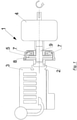
- the clutch of the invention is used to transmit motion from the flywheel 2 of a motor 3 to a conducted machine or gearbox 4.
- the clutch 1 has an outer shell 5, which receives the rotation motion from the flywheel 2.
- the rotation of the shell 5 is then transmitted to fixed sectors 6, mutually spaced and between which the floating sectors 7 of the clutch 1 are arranged.
- the aforementioned sectors 7 are suitable for moving radially towards the external side of the clutch, in the space between the fixed sectors 6, until they come into contact with a ring 8 which forms the conducted part of the clutch and which is rotated through the aforementioned contact with the floating sectors 7.
- the rotation of the ring 8 is transmitted to the shaft 9 which forms an integral part therewith and, hence, to the gearbox 4.
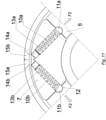
- each floating sector 7 is provided with an adjustable effort holding device of the same sector 7 on the respective fixed sectors 6 adjacent to it.
- this device consists of a spring 10 provided at its ends with spheres 11 which snap fit into the respective locations 12 provided on the sides of the fixed sectors 6 which face the corresponding sides of the floating sectors 7.
- the floating sectors 7 in turn have a through seat 13 for housing the aforementioned spring 10.
- This seat 13 is in a position aligned with the locations 12 of the fixed sectors 6, so as to achieve a corresponding alignment between the spheres 11 of the spring 10 and said locations 12.
- the spheres 11 are in an unstable equilibrium condition, arranged outside their location 12 and resting against the edge of the aforementioned locations 12 of the fixed sectors 6.
- the decrease in the speed revolution of motor 3 corresponds to a similar decrease in the centrifugal force F3, which allows the spring 10 to recall the spheres 11 within their locations 12 in the aforementioned sectors 6.
- each floating sector 7 is provided with two locations 13a, 13b for respective springs 10a, 10b each provided, at the end facing the external side of the clutch, with a threaded dowel 14a, 14b suitable for adjusting the elastic force F2 with which the springs 10a, 10b hold the corresponding floating sector 7 in place on the respective fixed sectors 6.
- a threaded dowel 14a, 14b suitable for adjusting the elastic force F2 with which the springs 10a, 10b hold the corresponding floating sector 7 in place on the respective fixed sectors 6.
- the ends of the springs 10a, 10b which face the respective fixed sector 6 are instead provided with spheres 11a, 11b suitable for being housed in the respective locations 12 of the corresponding fixed sectors 6.
- a leaf spring mechanism is used, of the type formed by a leaf spring 16 which compresses the spheres 11 in the locations 12 of the fixed sectors 6.
- the spring 10 is replaced by pneumatically or hydraulically actuated pistons 18, provided with a system 19 for controlling the force holding the floating sectors 7 in place on the fixed sectors 6.
- Said system 19 can for example consist of pads with a seal pushed by the dowel 20.
- the springs 10 are transferred from the floating sectors 7 to the fixed ones 6, according to an operating principle which substantially repeats that described by figures 4 and 6 above.
- the spring 10 - sphere 11 system is placed on the fixed sectors 6, the only sphere 11 being housed inside the corresponding location 12 provided on the respective floating sector 7.
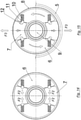
- figure 14 illustrates the clutch in its neutral position, while in figure 15 the clutch is in its engagement position, when the spheres 11 are in an unstable equilibrium condition, resting on the edge of the locations 12 which face the clutch interior, i.e. closer to the shaft 9 of the latter.
- a similar arrangement is also applicable to the described control systems with leaf-spring mechanism, or with pneumatically or hydraulically actuated pistons, mounted on the fixed sectors instead of on the floating ones.
- the clutch of the invention is provided with four floating sectors 7, mounted so as to slide in the space between an equal number of fixed sectors 6.
Landscapes
- Engineering & Computer Science (AREA)
- General Engineering & Computer Science (AREA)
- Mechanical Engineering (AREA)
- One-Way And Automatic Clutches, And Combinations Of Different Clutches (AREA)
- Mechanical Operated Clutches (AREA)
- Pulleys (AREA)
Claims (7)
- Fliehkraftkupplung vom Typ, der eine äußere Hülle (5) zum Aufnehmen einer Drehbewegung eines Motors (3), einen internen Führungsteil (8, 9), feste Abschnitte (6), die voneinander beabstandet sind, sowie schwebende Abschnitte (7), die in dem Zwischenraum zwischen den festen Abschnitten (6) schwebend angeordnet sind, aufweist, wobei eine Drehung der äußeren Hülle (5) auf die festen Abschnitte (6) übertragen wird, wobei die schwebenden Abschnitte (7) zum Bewegen radial in Richtung der externen Seite der Kupplung geeignet sind, bis sie mit einem Ring (8) des Führungsteils (8, 9) in Kontakt kommen, wobei die zuvor erwähnten schwebenden Abschnitte (7) mit Steuervorrichtungen zum Halten der schwebenden Abschnitte (7) auf den entsprechenden festen Abschnitte (6) benachbart zu ihnen ausgestattet sind, welche die Kopplungsverbindung und -trennung derselben schwebenden Abschnitte (7) in Bezug auf die festen Abschnitte (6), in Abhängigkeit von der Drehzahl der äußeren Hülle (5), bestimmen, wobei die erwähnten Steuervorrichtungen aus Federn (10, 16, 18) (10) bestehen, die in Übereinstimmung mit den schwebenden Abschnitten (7) positioniert und an ihren Enden mit Kugeln (11) vorgesehen sind, die in jeweilige Stellen (12), die auf den entsprechenden Seiten der festen Abschnitte (6) vorgesehen sind, einrasten, wobei die Kugeln (11) in der Eingriffsposition der Kupplung in einem instabilen Gleichgewichtszustand auf der Kante der zuvor erwähnten Stellen (12) der festen Abschnitte (6) angeordnet sind, sodass, wenn die Drehzahl der äußeren Hülle (5) kleiner ist als ein vorbestimmter Wert, es zu einer entsprechenden Abnahme der Fliehkraft kommt, welche es den Federn (10) ermöglicht, die Kugeln (11) in ihre Stellen (12) in denselben festen Abschnitten (6) zurückzuführen.
- Fliehkraftkupplung vom Typ, der eine äußere Hülle (5) zum Aufnehmen einer Drehbewegung eines Motors (3), einen internen Führungsteil (8, 9), feste Abschnitte (6), die voneinander beabstandet sind, sowie schwebende Abschnitte (7), die in dem Zwischenraum zwischen den festen Abschnitten (6) schwebend angeordnet sind, aufweist, wobei eine Drehung der äußeren Hülle (5) auf die festen Abschnitte (6) übertragen wird, wobei die schwebenden Abschnitte (7) zum Bewegen radial in Richtung der externen Seite der Kupplung geeignet sind, bis sie mit einem Ring (8) des Führungsteils (8, 9) in Kontakt kommen, wobei die zuvor erwähnten schwebenden Abschnitte (7) mit Steuervorrichtungen zum Halten der schwebenden Abschnitte (7) auf den entsprechenden festen Abschnitte (6) benachbart zu ihnen ausgestattet sind, welche die Kopplungsverbindung und -trennung derselben schwebenden Abschnitte (7) in Bezug auf die festen Abschnitte (6), in Abhängigkeit von der Drehzahl der äußeren Hülle (5), bestimmen, wobei die zuvor erwähnten Steuervorrichtungen aus Federn (10, 16, 18) bestehen, die an den zuvor erwähnten festen Abschnitten (6) angeordnet und an ihren Enden mit einer Kugel (11) vorgesehen sind, die in die Stelle (12), die auf der entsprechenden Seite der schwebenden Abschnitte (7) vorgesehen ist, einrastet, wobei die Kugeln (11) in dem Eingriffszustand der Kupplung in einem instabilen Gleichgewichtszustand auf der Kante der zuvor erwähnten Stellen (12) der schwebenden Abschnitte (7) angeordnet sind, sodass, wenn die Drehzahl der äußeren Hülle (5) kleiner ist als ein vorbestimmter Wert, es zu einer entsprechenden Abnahme der Fliehkraft kommt, welche es den Federn (10) ermöglicht, die Kugeln (11) in ihre Stellen (12) in denselben schwebenden Abschnitten (7) zurückzuführen.
- Kupplung nach einem der Ansprüche 1 oder 2, dadurch gekennzeichnet, dass, wenn die Drehzahl der äußeren Hülle (5) niedriger ist als ein vorbestimmter Wert, die Fliehkraft (F1), welche auf den schwebenden Abschnitten (7) erzeugt wird, kleiner ist als die Widerstandskraft (F2), mit welcher die Steuervorrichtungen die Abschnitte (7) zwischen den festen Abschnitten (6) halten, wobei die schwebenden Abschnitte (7) in diesem Zustand mit den festen Abschnitten (6) gekoppelt gehalten werden und die Kupplung (1) sich in einer Leerlaufstellung befindet.
- Kupplung nach einem der Ansprüche 1 oder 2, dadurch gekennzeichnet, dass, wenn die Drehzahl der äußeren Hülle (5) höher ist als ein vorbestimmter Wert, die Fliehkraft (F3), welche auf den schwebenden Abschnitten (7) erzeugt wird, größer ist als die Widerstandskraft (F2), mit welcher die Steuervorrichtungen die Abschnitte (7) zwischen den festen Abschnitten (6) halten, wobei die schwebenden Abschnitte (7) in diesem Zustand von den festen Abschnitten (6) getrennt werden und die Kupplung (1) in Eingriff steht.
- Kupplung nach Anspruch 1, dadurch gekennzeichnet, dass die zuvor erwähnten schwebenden Abschnitte (7) einen Durchgangssitz (13) aufweisen, welcher die Feder (10) unterbringt, wobei der zuvor erwähnte Sitz (13) mit den Stellen (12) der festen Abschnitte (6) ausgerichtet angeordnet ist.
- Kupplung nach einem der Ansprüche 1 oder 2, dadurch gekennzeichnet, dass die zuvor erwähnten Steuervorrichtungen aus Federn (10a, 10b) bestehen, die in ihren jeweiligen Stellen (13a, 13b) jedes schwebenden Abschnitts (7) positioniert sind, wobei das Ende der Federn (10a, 10b), das der externen Seite der Kupplung zugewandt ist, einen mit einem Gewinde versehenen Zapfen (14a, 14b) aufweist, der zum Einstellen der Federkraft (F2) geeignet ist, mit welcher die Federn (10a, 10b) den jeweiligen schwebenden Abschnitt (7) auf den jeweiligen festen Abschnitten (6) an Ort und Stelle halten, wobei eine entsprechende Kugel (11a, 11b) an dem Ende der zuvor erwähnten Federn (10a, 10b) vorgesehen ist, das dem jeweiligen festen Abschnitt (6) zugewandt ist.
- Kupplung nach einem der Ansprüche 1 oder 2, dadurch gekennzeichnet, dass Federn (10, 16, 18) von zuvor erwähnten Steuervorrichtungen aus Blattfeder-Mechanismen (16) oder Kolben (18) mit pneumatischer oder hydraulischer Betätigung bestehen.
Applications Claiming Priority (1)
| Application Number | Priority Date | Filing Date | Title |
|---|---|---|---|
| IT102019000012840A IT201900012840A1 (it) | 2019-07-25 | 2019-07-25 | Frizione centrifuga di tipo migliorato |
Publications (2)
| Publication Number | Publication Date |
|---|---|
| EP3770455A1 EP3770455A1 (de) | 2021-01-27 |
| EP3770455B1 true EP3770455B1 (de) | 2022-03-09 |
Family
ID=69173116
Family Applications (1)
| Application Number | Title | Priority Date | Filing Date |
|---|---|---|---|
| EP20186856.9A Active EP3770455B1 (de) | 2019-07-25 | 2020-07-21 | Fliehkraftreibungskupplung mit schwungmassen selbst als kupplungsglieder |
Country Status (2)
| Country | Link |
|---|---|
| EP (1) | EP3770455B1 (de) |
| IT (1) | IT201900012840A1 (de) |
Family Cites Families (7)
| Publication number | Priority date | Publication date | Assignee | Title |
|---|---|---|---|---|
| US2166357A (en) * | 1934-03-02 | 1939-07-18 | Rex E Keller | Automatic transmission clutch |
| FR828455A (fr) * | 1937-01-27 | 1938-05-18 | Panhard & Levassor | Embrayage |
| DE677239C (de) * | 1937-05-12 | 1939-06-21 | Bosch Gmbh Robert | Fliehkraftkupplung |
| US2991865A (en) * | 1959-11-12 | 1961-07-11 | Norman B Wilson | Anti-rattle assembly for a centrifugal clutch |
| US3367464A (en) * | 1965-09-13 | 1968-02-06 | American Lincoln Corp | Centrifugal clutch |
| DE202007002755U1 (de) * | 2007-02-24 | 2007-04-26 | Amsbeck Maschinentechnik Gmbh | Fliehkraftkupplung |
| US8613351B2 (en) * | 2011-05-23 | 2013-12-24 | The Hilliard Corporation | Centrifugal clutch with heat mitigating spring arrangement |
-
2019
- 2019-07-25 IT IT102019000012840A patent/IT201900012840A1/it unknown
-
2020
- 2020-07-21 EP EP20186856.9A patent/EP3770455B1/de active Active
Also Published As
| Publication number | Publication date |
|---|---|
| IT201900012840A1 (it) | 2021-01-25 |
| EP3770455A1 (de) | 2021-01-27 |
Similar Documents
| Publication | Publication Date | Title |
|---|---|---|
| EP3129671B1 (de) | Riemenscheibenanordnung mit radial ausgerichtetem entkopplungsmechanismus | |
| US3971463A (en) | Progressively engaged centrifugal clutch | |
| US3580372A (en) | Clutch with adjustable centrifugal pressure assist levers | |
| US1618644A (en) | Centrifugal clutch | |
| JP5444153B2 (ja) | クラッチ装置 | |
| EP3099952B1 (de) | Zusammengesetzte rutsch- und klauenkupplung | |
| EP0286213A1 (de) | Torsionsschwingungsdämpfer | |
| AU2013277130A1 (en) | Accessory drive decoupler | |
| US5154683A (en) | Clutch having rotatable friction rings | |
| CN112823121B (zh) | 多片离合器式变速器和包括多片离合器式变速器的海上交通工具 | |
| US2257987A (en) | Clutch construction | |
| US3187862A (en) | Clutch mechanism with flexspline | |
| US5333712A (en) | Synchronized clutch | |
| EP3770455B1 (de) | Fliehkraftreibungskupplung mit schwungmassen selbst als kupplungsglieder | |
| US2771977A (en) | Cam operated clutch | |
| GB2209195A (en) | Fluid operated multiple-disk friction clutch | |
| JP2019090429A (ja) | クラッチ装置 | |
| JP2005098446A (ja) | ダンパ装置、及びクラッチ装置 | |
| EP2522872B1 (de) | Reibkupplung mit zentrifugaler Schaltung | |
| US1985127A (en) | Power transmitting mechanism | |
| JP4176168B2 (ja) | 遠心クラッチ | |
| US2219877A (en) | Clutch construction | |
| GB694722A (en) | Improvements in or relating to devices for shifting spring systems | |
| US1967749A (en) | Automatic clutch | |
| US5067602A (en) | Internally assisted clutch |
Legal Events
| Date | Code | Title | Description |
|---|---|---|---|
| PUAI | Public reference made under article 153(3) epc to a published international application that has entered the european phase |
Free format text: ORIGINAL CODE: 0009012 |
|
| STAA | Information on the status of an ep patent application or granted ep patent |
Free format text: STATUS: THE APPLICATION HAS BEEN PUBLISHED |
|
| AK | Designated contracting states |
Kind code of ref document: A1 Designated state(s): AL AT BE BG CH CY CZ DE DK EE ES FI FR GB GR HR HU IE IS IT LI LT LU LV MC MK MT NL NO PL PT RO RS SE SI SK SM TR |
|
| AX | Request for extension of the european patent |
Extension state: BA ME |
|
| STAA | Information on the status of an ep patent application or granted ep patent |
Free format text: STATUS: REQUEST FOR EXAMINATION WAS MADE |
|
| 17P | Request for examination filed |
Effective date: 20210712 |
|
| RBV | Designated contracting states (corrected) |
Designated state(s): AL AT BE BG CH CY CZ DE DK EE ES FI FR GB GR HR HU IE IS IT LI LT LU LV MC MK MT NL NO PL PT RO RS SE SI SK SM TR |
|
| GRAP | Despatch of communication of intention to grant a patent |
Free format text: ORIGINAL CODE: EPIDOSNIGR1 |
|
| STAA | Information on the status of an ep patent application or granted ep patent |
Free format text: STATUS: GRANT OF PATENT IS INTENDED |
|
| INTG | Intention to grant announced |
Effective date: 20211103 |
|
| GRAS | Grant fee paid |
Free format text: ORIGINAL CODE: EPIDOSNIGR3 |
|
| GRAA | (expected) grant |
Free format text: ORIGINAL CODE: 0009210 |
|
| STAA | Information on the status of an ep patent application or granted ep patent |
Free format text: STATUS: THE PATENT HAS BEEN GRANTED |
|
| AK | Designated contracting states |
Kind code of ref document: B1 Designated state(s): AL AT BE BG CH CY CZ DE DK EE ES FI FR GB GR HR HU IE IS IT LI LT LU LV MC MK MT NL NO PL PT RO RS SE SI SK SM TR |
|
| REG | Reference to a national code |
Ref country code: CH Ref legal event code: EP Ref country code: AT Ref legal event code: REF Ref document number: 1474393 Country of ref document: AT Kind code of ref document: T Effective date: 20220315 |
|
| REG | Reference to a national code |
Ref country code: IE Ref legal event code: FG4D |
|
| REG | Reference to a national code |
Ref country code: DE Ref legal event code: R096 Ref document number: 602020002141 Country of ref document: DE |
|
| REG | Reference to a national code |
Ref country code: LT Ref legal event code: MG9D |
|
| REG | Reference to a national code |
Ref country code: NL Ref legal event code: MP Effective date: 20220309 |
|
| PG25 | Lapsed in a contracting state [announced via postgrant information from national office to epo] |
Ref country code: SE Free format text: LAPSE BECAUSE OF FAILURE TO SUBMIT A TRANSLATION OF THE DESCRIPTION OR TO PAY THE FEE WITHIN THE PRESCRIBED TIME-LIMIT Effective date: 20220309 Ref country code: RS Free format text: LAPSE BECAUSE OF FAILURE TO SUBMIT A TRANSLATION OF THE DESCRIPTION OR TO PAY THE FEE WITHIN THE PRESCRIBED TIME-LIMIT Effective date: 20220309 Ref country code: NO Free format text: LAPSE BECAUSE OF FAILURE TO SUBMIT A TRANSLATION OF THE DESCRIPTION OR TO PAY THE FEE WITHIN THE PRESCRIBED TIME-LIMIT Effective date: 20220609 Ref country code: LT Free format text: LAPSE BECAUSE OF FAILURE TO SUBMIT A TRANSLATION OF THE DESCRIPTION OR TO PAY THE FEE WITHIN THE PRESCRIBED TIME-LIMIT Effective date: 20220309 Ref country code: HR Free format text: LAPSE BECAUSE OF FAILURE TO SUBMIT A TRANSLATION OF THE DESCRIPTION OR TO PAY THE FEE WITHIN THE PRESCRIBED TIME-LIMIT Effective date: 20220309 Ref country code: BG Free format text: LAPSE BECAUSE OF FAILURE TO SUBMIT A TRANSLATION OF THE DESCRIPTION OR TO PAY THE FEE WITHIN THE PRESCRIBED TIME-LIMIT Effective date: 20220609 |
|
| PG25 | Lapsed in a contracting state [announced via postgrant information from national office to epo] |
Ref country code: LV Free format text: LAPSE BECAUSE OF FAILURE TO SUBMIT A TRANSLATION OF THE DESCRIPTION OR TO PAY THE FEE WITHIN THE PRESCRIBED TIME-LIMIT Effective date: 20220309 Ref country code: GR Free format text: LAPSE BECAUSE OF FAILURE TO SUBMIT A TRANSLATION OF THE DESCRIPTION OR TO PAY THE FEE WITHIN THE PRESCRIBED TIME-LIMIT Effective date: 20220610 Ref country code: FI Free format text: LAPSE BECAUSE OF FAILURE TO SUBMIT A TRANSLATION OF THE DESCRIPTION OR TO PAY THE FEE WITHIN THE PRESCRIBED TIME-LIMIT Effective date: 20220309 |
|
| PG25 | Lapsed in a contracting state [announced via postgrant information from national office to epo] |
Ref country code: NL Free format text: LAPSE BECAUSE OF FAILURE TO SUBMIT A TRANSLATION OF THE DESCRIPTION OR TO PAY THE FEE WITHIN THE PRESCRIBED TIME-LIMIT Effective date: 20220309 |
|
| PG25 | Lapsed in a contracting state [announced via postgrant information from national office to epo] |
Ref country code: SM Free format text: LAPSE BECAUSE OF FAILURE TO SUBMIT A TRANSLATION OF THE DESCRIPTION OR TO PAY THE FEE WITHIN THE PRESCRIBED TIME-LIMIT Effective date: 20220309 Ref country code: SK Free format text: LAPSE BECAUSE OF FAILURE TO SUBMIT A TRANSLATION OF THE DESCRIPTION OR TO PAY THE FEE WITHIN THE PRESCRIBED TIME-LIMIT Effective date: 20220309 Ref country code: RO Free format text: LAPSE BECAUSE OF FAILURE TO SUBMIT A TRANSLATION OF THE DESCRIPTION OR TO PAY THE FEE WITHIN THE PRESCRIBED TIME-LIMIT Effective date: 20220309 Ref country code: PT Free format text: LAPSE BECAUSE OF FAILURE TO SUBMIT A TRANSLATION OF THE DESCRIPTION OR TO PAY THE FEE WITHIN THE PRESCRIBED TIME-LIMIT Effective date: 20220711 Ref country code: ES Free format text: LAPSE BECAUSE OF FAILURE TO SUBMIT A TRANSLATION OF THE DESCRIPTION OR TO PAY THE FEE WITHIN THE PRESCRIBED TIME-LIMIT Effective date: 20220309 Ref country code: EE Free format text: LAPSE BECAUSE OF FAILURE TO SUBMIT A TRANSLATION OF THE DESCRIPTION OR TO PAY THE FEE WITHIN THE PRESCRIBED TIME-LIMIT Effective date: 20220309 Ref country code: CZ Free format text: LAPSE BECAUSE OF FAILURE TO SUBMIT A TRANSLATION OF THE DESCRIPTION OR TO PAY THE FEE WITHIN THE PRESCRIBED TIME-LIMIT Effective date: 20220309 |
|
| PG25 | Lapsed in a contracting state [announced via postgrant information from national office to epo] |
Ref country code: PL Free format text: LAPSE BECAUSE OF FAILURE TO SUBMIT A TRANSLATION OF THE DESCRIPTION OR TO PAY THE FEE WITHIN THE PRESCRIBED TIME-LIMIT Effective date: 20220309 Ref country code: IS Free format text: LAPSE BECAUSE OF FAILURE TO SUBMIT A TRANSLATION OF THE DESCRIPTION OR TO PAY THE FEE WITHIN THE PRESCRIBED TIME-LIMIT Effective date: 20220709 Ref country code: AL Free format text: LAPSE BECAUSE OF FAILURE TO SUBMIT A TRANSLATION OF THE DESCRIPTION OR TO PAY THE FEE WITHIN THE PRESCRIBED TIME-LIMIT Effective date: 20220309 |
|
| REG | Reference to a national code |
Ref country code: DE Ref legal event code: R097 Ref document number: 602020002141 Country of ref document: DE |
|
| PLBE | No opposition filed within time limit |
Free format text: ORIGINAL CODE: 0009261 |
|
| STAA | Information on the status of an ep patent application or granted ep patent |
Free format text: STATUS: NO OPPOSITION FILED WITHIN TIME LIMIT |
|
| PG25 | Lapsed in a contracting state [announced via postgrant information from national office to epo] |
Ref country code: DK Free format text: LAPSE BECAUSE OF FAILURE TO SUBMIT A TRANSLATION OF THE DESCRIPTION OR TO PAY THE FEE WITHIN THE PRESCRIBED TIME-LIMIT Effective date: 20220309 |
|
| 26N | No opposition filed |
Effective date: 20221212 |
|
| PG25 | Lapsed in a contracting state [announced via postgrant information from national office to epo] |
Ref country code: SI Free format text: LAPSE BECAUSE OF FAILURE TO SUBMIT A TRANSLATION OF THE DESCRIPTION OR TO PAY THE FEE WITHIN THE PRESCRIBED TIME-LIMIT Effective date: 20220309 Ref country code: MC Free format text: LAPSE BECAUSE OF FAILURE TO SUBMIT A TRANSLATION OF THE DESCRIPTION OR TO PAY THE FEE WITHIN THE PRESCRIBED TIME-LIMIT Effective date: 20220309 |
|
| REG | Reference to a national code |
Ref country code: BE Ref legal event code: MM Effective date: 20220731 |
|
| PG25 | Lapsed in a contracting state [announced via postgrant information from national office to epo] |
Ref country code: LU Free format text: LAPSE BECAUSE OF NON-PAYMENT OF DUE FEES Effective date: 20220721 Ref country code: FR Free format text: LAPSE BECAUSE OF NON-PAYMENT OF DUE FEES Effective date: 20220731 |
|
| PG25 | Lapsed in a contracting state [announced via postgrant information from national office to epo] |
Ref country code: BE Free format text: LAPSE BECAUSE OF NON-PAYMENT OF DUE FEES Effective date: 20220731 |
|
| P01 | Opt-out of the competence of the unified patent court (upc) registered |
Effective date: 20230324 |
|
| PG25 | Lapsed in a contracting state [announced via postgrant information from national office to epo] |
Ref country code: IT Free format text: LAPSE BECAUSE OF FAILURE TO SUBMIT A TRANSLATION OF THE DESCRIPTION OR TO PAY THE FEE WITHIN THE PRESCRIBED TIME-LIMIT Effective date: 20220309 Ref country code: IE Free format text: LAPSE BECAUSE OF NON-PAYMENT OF DUE FEES Effective date: 20220721 |
|
| REG | Reference to a national code |
Ref country code: CH Ref legal event code: PL |
|
| PG25 | Lapsed in a contracting state [announced via postgrant information from national office to epo] |
Ref country code: MK Free format text: LAPSE BECAUSE OF FAILURE TO SUBMIT A TRANSLATION OF THE DESCRIPTION OR TO PAY THE FEE WITHIN THE PRESCRIBED TIME-LIMIT Effective date: 20220309 Ref country code: CY Free format text: LAPSE BECAUSE OF FAILURE TO SUBMIT A TRANSLATION OF THE DESCRIPTION OR TO PAY THE FEE WITHIN THE PRESCRIBED TIME-LIMIT Effective date: 20220309 Ref country code: CH Free format text: LAPSE BECAUSE OF NON-PAYMENT OF DUE FEES Effective date: 20230731 |
|
| REG | Reference to a national code |
Ref country code: AT Ref legal event code: UEP Ref document number: 1474393 Country of ref document: AT Kind code of ref document: T Effective date: 20220309 |
|
| PG25 | Lapsed in a contracting state [announced via postgrant information from national office to epo] |
Ref country code: HU Free format text: LAPSE BECAUSE OF FAILURE TO SUBMIT A TRANSLATION OF THE DESCRIPTION OR TO PAY THE FEE WITHIN THE PRESCRIBED TIME-LIMIT; INVALID AB INITIO Effective date: 20200721 |
|
| PG25 | Lapsed in a contracting state [announced via postgrant information from national office to epo] |
Ref country code: TR Free format text: LAPSE BECAUSE OF FAILURE TO SUBMIT A TRANSLATION OF THE DESCRIPTION OR TO PAY THE FEE WITHIN THE PRESCRIBED TIME-LIMIT Effective date: 20220309 |
|
| PG25 | Lapsed in a contracting state [announced via postgrant information from national office to epo] |
Ref country code: MT Free format text: LAPSE BECAUSE OF FAILURE TO SUBMIT A TRANSLATION OF THE DESCRIPTION OR TO PAY THE FEE WITHIN THE PRESCRIBED TIME-LIMIT Effective date: 20220309 |
|
| GBPC | Gb: european patent ceased through non-payment of renewal fee |
Effective date: 20240721 |
|
| PG25 | Lapsed in a contracting state [announced via postgrant information from national office to epo] |
Ref country code: GB Free format text: LAPSE BECAUSE OF NON-PAYMENT OF DUE FEES Effective date: 20240721 |
|
| PGFP | Annual fee paid to national office [announced via postgrant information from national office to epo] |
Ref country code: DE Payment date: 20250728 Year of fee payment: 6 |
|
| PGFP | Annual fee paid to national office [announced via postgrant information from national office to epo] |
Ref country code: AT Payment date: 20250718 Year of fee payment: 6 |