EP3770575B1 - Procédé de commande de vibration multidimensionnel pour un modèle d'aéronef monté sur une balance-dard - Google Patents
Procédé de commande de vibration multidimensionnel pour un modèle d'aéronef monté sur une balance-dard Download PDFInfo
- Publication number
- EP3770575B1 EP3770575B1 EP19877532.2A EP19877532A EP3770575B1 EP 3770575 B1 EP3770575 B1 EP 3770575B1 EP 19877532 A EP19877532 A EP 19877532A EP 3770575 B1 EP3770575 B1 EP 3770575B1
- Authority
- EP
- European Patent Office
- Prior art keywords
- vibration
- real
- acceleration
- piezoelectric ceramic
- time
- Prior art date
- Legal status (The legal status is an assumption and is not a legal conclusion. Google has not performed a legal analysis and makes no representation as to the accuracy of the status listed.)
- Not-in-force
Links
Images



Classifications
-
- G—PHYSICS
- G01—MEASURING; TESTING
- G01M—TESTING STATIC OR DYNAMIC BALANCE OF MACHINES OR STRUCTURES; TESTING OF STRUCTURES OR APPARATUS, NOT OTHERWISE PROVIDED FOR
- G01M9/00—Aerodynamic testing; Arrangements in or on wind tunnels
- G01M9/08—Aerodynamic models
-
- G—PHYSICS
- G01—MEASURING; TESTING
- G01M—TESTING STATIC OR DYNAMIC BALANCE OF MACHINES OR STRUCTURES; TESTING OF STRUCTURES OR APPARATUS, NOT OTHERWISE PROVIDED FOR
- G01M9/00—Aerodynamic testing; Arrangements in or on wind tunnels
- G01M9/02—Wind tunnels
- G01M9/04—Details
-
- B—PERFORMING OPERATIONS; TRANSPORTING
- B64—AIRCRAFT; AVIATION; COSMONAUTICS
- B64F—GROUND OR AIRCRAFT-CARRIER-DECK INSTALLATIONS SPECIALLY ADAPTED FOR USE IN CONNECTION WITH AIRCRAFT; DESIGNING, MANUFACTURING, ASSEMBLING, CLEANING, MAINTAINING OR REPAIRING AIRCRAFT, NOT OTHERWISE PROVIDED FOR; HANDLING, TRANSPORTING, TESTING OR INSPECTING AIRCRAFT COMPONENTS, NOT OTHERWISE PROVIDED FOR
- B64F5/00—Designing, manufacturing, assembling, cleaning, maintaining or repairing aircraft, not otherwise provided for; Handling, transporting, testing or inspecting aircraft components, not otherwise provided for
- B64F5/60—Testing or inspecting aircraft components or systems
-
- G—PHYSICS
- G01—MEASURING; TESTING
- G01M—TESTING STATIC OR DYNAMIC BALANCE OF MACHINES OR STRUCTURES; TESTING OF STRUCTURES OR APPARATUS, NOT OTHERWISE PROVIDED FOR
- G01M7/00—Vibration-testing of structures; Shock-testing of structures
-
- G—PHYSICS
- G01—MEASURING; TESTING
- G01M—TESTING STATIC OR DYNAMIC BALANCE OF MACHINES OR STRUCTURES; TESTING OF STRUCTURES OR APPARATUS, NOT OTHERWISE PROVIDED FOR
- G01M9/00—Aerodynamic testing; Arrangements in or on wind tunnels
- G01M9/06—Measuring arrangements specially adapted for aerodynamic testing
- G01M9/062—Wind tunnel balances; Holding devices combined with measuring arrangements
-
- G—PHYSICS
- G01—MEASURING; TESTING
- G01P—MEASURING LINEAR OR ANGULAR SPEED, ACCELERATION, DECELERATION, OR SHOCK; INDICATING PRESENCE, ABSENCE, OR DIRECTION, OF MOVEMENT
- G01P15/00—Measuring acceleration; Measuring deceleration; Measuring shock, i.e. sudden change of acceleration
- G01P15/02—Measuring acceleration; Measuring deceleration; Measuring shock, i.e. sudden change of acceleration by making use of inertia forces using solid seismic masses
-
- H—ELECTRICITY
- H10—SEMICONDUCTOR DEVICES; ELECTRIC SOLID-STATE DEVICES NOT OTHERWISE PROVIDED FOR
- H10N—ELECTRIC SOLID-STATE DEVICES NOT OTHERWISE PROVIDED FOR
- H10N30/00—Piezoelectric or electrostrictive devices
- H10N30/101—Piezoelectric or electrostrictive devices with electrical and mechanical input and output, e.g. having combined actuator and sensor parts
-
- H—ELECTRICITY
- H10—SEMICONDUCTOR DEVICES; ELECTRIC SOLID-STATE DEVICES NOT OTHERWISE PROVIDED FOR
- H10N—ELECTRIC SOLID-STATE DEVICES NOT OTHERWISE PROVIDED FOR
- H10N30/00—Piezoelectric or electrostrictive devices
- H10N30/80—Constructional details
- H10N30/85—Piezoelectric or electrostrictive active materials
- H10N30/853—Ceramic compositions
Definitions
- the present invention belongs to the field of active vibration control, and relates to a new multi-dimensional vibration control method for aircraft model based on piezoelectric ceramic actuator, which is applied to the wind tunnel test of aircraft model.
- Wind tunnel test is an important means in the research and development of core equipment or components in aviation field.
- the aircraft model is fixed on the Angle of attack adjustment mechanism by connecting the force balance with the wind tunnel tail brace strut, which is a typical cantilever beam system.
- the gas passing through the upper surface of the aircraft airfoil will no longer be attached to the airfoil surface and will fall off from the airfoil surface, and an eddy current will be generated behind the leading edge of the airfoil, resulting in random excitation to the aircraft model wing, coupled with the disturbance of the fluctuating air pressure in the wind tunnel itself and the wide-band unstable air flow such as the model wake flow.
- the vibration control of wind tunnel aircraft model is divided into passive vibration control mode and active vibration control mode.
- the passive vibration control mode is limited to specific large-space model and specific working condition, and the corresponding speed is slow, so the vibration control effect is not ideal. Therefore, the active vibration control method with strong universality, fast response speed and large output power is the one with the most research and practical significance.
- the pitch and yaw vibrations of test model decoupling control can achieve certain vibration control effect, but the main process of aircraft model in wind tunnel test vibration in longitudinal direction, the yaw direction vibration smaller aircraft model, decorate in the yaw direction and longitudinal direction the same number of piezoelectric ceramic actuator is used to control a lot of the yaw direction of vibration is smaller, result in vibration control of a large amount of waste, and to decompose the vibration in pitch and yaw plane respectively to control, not to the original main vibration control of the flying model, control process, the stability and reliability of the control system are affected when the piezoelectric ceramic components work in different planes.
- United States patent specification No. US 2018/067015 A1 discloses a balance protection system for a wind tunnel test system.
- the balance protection system disclosed includes a first set of features on a model component that mate with a second set of features on to a sting component.
- the clearances between the first and second set of features determine an amount of allowed movement of the model with respect to the balance.
- the technical problems to be solved by the present invention is to overcome the defects in the prior art. Aiming at the existing unidimensional vibration active control system is unable to effectively solve the multi-dimensional vibration generated during the process of the aircraft model wind tunnel test, which seriously affects the quality of test data and threatens the security of the wind tunnel test, a multi-dimensional vibration control method for the model of strut tail-supported aircraft is invented.
- the method adopts the active vibration control method, and the main vibration vector of the aircraft model is calculated through the arrangement in the center of mass of the aircraft model pitch and yaw acceleration sensor measuring acceleration component, and then determine the strut real-time vibration plane in the space.
- the dynamic bending moment and stress distribution on the active cross section of the multi-dimensional vibration damper are calculated by the inertial force.
- the spatial position of the real-time vibration plane of the strut determine the serial number of the piezoelectric ceramic actuator working in the multi-dimensional vibration damper and calculate the vibration control force in real-time.
- the reverse bending moment is generated to resist the dynamic bending moment in the process of aircraft model vibration, so as to achieve the purpose of vibration control.
- This method can effectively control the low-order, multi-dimensional, low-frequency and large amplitude vibration of the aircraft model in pitch plane, yaw plane and axial direction, and ensure the reasonable and efficient output of the control force of the piezoelectric ceramic actuator.
- the technical solution adopted by the invention is: a multi-dimensional vibration control method for the support tail-supported aircraft model, the method is performed through the arrangement of pitch and yaw acceleration sensors on the center of mass of the aircraft model, measuring the pitch and yaw components of main vibration acceleration of the aircraft model using the pitch and yaw acceleration sensors, characterized in that the method comprises the following steps: calculating the main vibration vector and determine the strut real-time aircraft model plane, introduction of inertial force to solve the multi-dimensional active vibration damper on cross section by dynamic bending moment, and then obtain the initiative stress distribution on cross section, through the real-time vibration plane space position relation of multi-dimensional vibration damper to participate in the work of piezoelectric ceramic actuator serial number.
- the vibration control force is calculated in real time according to the stress on the active section of the piezoelectric ceramic actuator, and then the dynamic bending moment is generated in the process of the reverse bending moment resisting the vibration of the aircraft model.
- the multi-dimensional vibration active control system based on piezoelectric ceramic actuator is adopted to control the multi-dimensional vibration. The specific steps are as follows:
- Step 1 establish the absolute coordinate system of the aircraft model support system
- the absolute coordinate system OXYZ E is established on the aircraft tail strut 4, and the coordinate origin is established in the equilibrium position at the intersection of the active section F and the axis of the aircraft tail strut 4, which is defined as O ;
- the direction of the X axis coincides with the balance position of the axis of aircraft tail strut 4 and points to the aircraft model 5,
- the direction of the Y axis is that the intersection of the active section F and the pitching plane points upward;
- the Z axis is determined by the right manipulation.
- the vibration measurement coordinate system O A X A Y A Z A A is established on the aircraft model 5, whose origin is established at the intersection of the center of mass of the aircraft model 5 and the X axis of the absolute coordinate system OXYZ E, which is defined as that the direction of the O A ;
- X A coordinate axis coincides with the X axis of the absolute coordinate system OXYZ E, the Y A coordinate axis and the Y axis of the absolute coordinate system OXYZ E point upward, and the Z A coordinate axis is determined by right manipulation.
- Step 2 calculating the components of the main vibration acceleration in the pitch plane and yaw plane in real time
- the acceleration component of the a pith ( t ) main vibration acceleration in the pitch direction the acceleration component of the a yaw ( t ) main vibration acceleration in the yaw direction
- N is the number of acceleration sampling values in each vibration control cycle.
- Step 3 solve the main vibration acceleration vector in real time
- the main vibration acceleration is obtained by combining the acceleration components in the pitching direction and yaw direction.
- the main vibration acceleration consists of magnitude and direction.
- a ( t ) is the main vibration acceleration vector
- is the magnitude of the vibration acceleration vector a ( t )
- ⁇ a ( t ) is the main vibration acceleration vector a ( t ) in directions.
- Step 4 establish the real-time vibration active control coordinate system of the aircraft model and determine the real-time vibration plane of the strut
- the real-time active vibration control coordinate system O ⁇ X ⁇ Y ⁇ Z ⁇ D is established on the active section F, and its origin coincides with the origin O of the absolute coordinate system OXYZ E. It is defined that the direction of the O ⁇ .
- X ⁇ axis coincides with the direction of the X coordinate of the absolute coordinate OXYZ E
- the Y ⁇ axis coincides with the a ( t ) direction of the main vibration acceleration vector
- the Z ⁇ coordinate axis is determined by the right manipulation.
- Plane X ⁇ O ⁇ Y ⁇ is the real-time vibration plane X ⁇ O ⁇ Y ⁇ C of the strut. Because of the randomness of the vibration of the aircraft model 5, the real-time active vibration control coordinate system O ⁇ X ⁇ Y ⁇ Z ⁇ D changes with time, and the real-time vibration plane X ⁇ O ⁇ Y C changes with time.
- Step 5 the real-time inertial force and the stress distribution on the active section of the support system are solved
- m eq is the equivalent mass of the support system
- F I ( t ) is the real-time inertia force acting on the aircraft model 5
- M ( t ) is the dynamic bending moment on the active section F of the aircraft model 5 during vibration
- L is the distance from the center of mass of the aircraft model 5 to the active section F
- ⁇ ( y a , z a , t ) is the dynamic stress at the length of the active section F inner distance X ⁇ coordinate axis y a
- I z ⁇ ( t ) is the real time inertia moment of the active section F to the Z ⁇ coordinate axis.
- Step 6 Determine the serial number of the piezoelectric actuator in real time and calculate the vibration control force
- a number of piezoelectric ceramic actuators 3-1 are uniformly arranged in the circumferential direction of the multi-dimensional vibration damper 3 at the active section F, the uniformly distributed circumferential radius is R, and the piezoelectric ceramic which coincides with the Z axis of the absolute coordinate system OXYZ E is set as No. 0 piezoelectric ceramic actuator 3-1, the No. 1 piezoelectric ceramic actuator 3-1, the No. 2 piezoelectric ceramic actuator 3-1, ..., the No. n piezoelectric ceramic actuator 3-1, are arranged in a counterclockwise circular array in turn.
- the piezoelectric ceramic actuator 3-1 above the Z ⁇ axis participates in the vibration control, and the serial number of the piezoelectric ceramic actuator 3-1 participating in the work is n c ⁇ INT ⁇ t ⁇ ⁇ 2 ⁇ ⁇ + 1 , INT ⁇ t + ⁇ 2 ⁇ ⁇
- all the piezoelectric ceramic actuators 3-1 generate a reverse bending moment M R (t) to resist the dynamic bending moment M(t) generated during the vibration of the aircraft model 5.
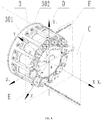
- the multi-dimensional vibration control method for the model of the strut tail-supported aircraft adopts the multi-dimensional vibration active control system, which is mainly composed of pitch acceleration sensor 6, yaw acceleration sensor 7, real-time controller 8, computer 9, piezoelectric ceramic actuator power amplifier group 10 and multi-dimensional vibration damper 3.
- the pitch acceleration sensor 6 is installed on the center of mass of the aircraft model 5 in the pitching plane and is used to measure the vibration acceleration component of the main vibration of the aircraft model 5 in the pitching plane;
- the yaw acceleration sensor 7 is installed on the center of mass of the aircraft model 5 in the yaw plane and is used to measure the vibration acceleration component of the main vibration of the aircraft model 5 in the yaw plane;
- the multi-dimensional vibration damper 3 includes a plurality of uniformly distributed piezoelectric ceramic actuators 3-1, each of which is pretightened by a pretightening mechanism 3-2, respectively, to ensure the reliable output of the dynamic force of the piezoelectric ceramic actuator 3-1.
- the multi-dimensional vibration damper 3 is installed in the real-time vibration plane X ⁇ O ⁇ Y ⁇ C of the aircraft tail strut 4, the real-time controller 8 is connected with the computer 9, and the computer 9 is used to control the real-time controller 8 and monitor the vibration control process.
- the real-time controller 8 is connected with the pitch acceleration sensor 6 and the yaw acceleration sensor 7 respectively to obtain the vibration acceleration components in the pitching plane and the yaw plane of the aircraft model 5 in real time; the real-time controller 8 is connected to a piezoelectric ceramic actuator power amplifier group 10, and a plurality of piezoelectric ceramic actuator power amplifiers 10-1 in the piezoelectric ceramic actuator power amplifier group 10 are respectively connected to a plurality of piezoelectric ceramic actuators 3-1 in the multi-dimensional vibration damper 3.
- the benefits of the present invention Compared with the existing active vibration control system of wind tunnel aircraft model and the method thereof, the present method and system can realize effective control of low-order multi-dimensional low-frequency significant vibration for the aircraft model on pitch plane and yaw plane and the axis direction in transonic wind tunnel experiment.
- the calculation method of vibration control force is presented to ensure the reasonable and efficient output of actuator control force in the process of random vibration control, avoid the existing different plane piezoelectric ceramic components interact with each other at work, prolong the service life of the piezoelectric ceramic actuator, improve the active vibration control system stability and reliability of wind tunnel model. Furthermore, the quality of wind tunnel test data and the safety of wind tunnel test are ensured.
- the multi-dimensional active vibration control system is mainly composed of the pitch acceleration sensor 6, yaw acceleration sensor 7, real-time controller 8, computer 9, piezoelectric ceramic actuator power amplifier group 10 and multi-dimensional vibration damper 3.
- the pitch acceleration sensor 6 is installed on the center of mass of the aircraft model 5 in the pitching plane and is used to measure the vibration acceleration component of the main vibration of the aircraft model 5 in the pitching plane.
- the yaw acceleration sensor 7 is installed on the center of mass of the aircraft model 5 in the yaw plane and is used to measure the vibration acceleration component of the main vibration of the aircraft model 5 in the yaw plane.
- the multi-dimensional vibration damper 3 contains multiple piezoelectric ceramic actuators 3-1.
- each piezoelectric ceramic actuator 3-1 is pretightened through the pretightening mechanism 3-2 respectively to ensure the reliable output of the piezoelectric ceramic actuator 3-1 dynamic force.
- the multidimensional vibration damper 3 is installed at the fixed end of the aircraft tail strut 4, and the real-time controller 8 is connected to the computer 9, which is used to control the real-time controller 8 and the vibration control process monitoring.
- the real-time controller 8 is connected to the pitch acceleration sensor 6 and yaw acceleration sensor 7 respectively to obtain the vibration acceleration components in the pitch plane and yaw plane of the aircraft model 5 in real time.
- the real-time controller 8 is connected to the piezoelectric ceramic actuator power amplifier set 10, and there are 12 piezoelectric ceramic actuator power amplifiers 10-1 in the piezoelectric ceramic actuator power amplifier set 10, which are connected to 12 piezoelectric ceramic actuator 3-1 in the multi-dimensional vibration damper 3.
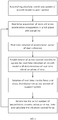
- Fig. 1 is a flow chart of a multi-dimensional vibration control method for a strut tail-supported aircraft model, which adopts a pitch acceleration sensor 6 and a yaw acceleration sensor 7 arranged at the center of mass of the aircraft model 5 to measure the vibration acceleration components a pith ( t ) and a yaw ( t ) of the main vibration in the mutually perpendicular pitch plane and the yaw plane respectively, and feedback them to the real-time controller 8 controlled by the computer 9.
- the real-time controller 8 calculates the main vibration acceleration vector a ( t ) in real time and determines the real-time vibration plane X ⁇ O ⁇ Y ⁇ C of the aircraft tail strut, calculates the dynamic bending moment M(t) on the active section F of the multi-dimensional vibration damper 3 through the inertia force F I ( t ), and then obtains the stress distribution on the active section F.
- the serial number of the piezoelectric ceramic actuator 3-1 in the multi-dimensional vibration damper 3 is determined through the spatial position relationship of the real-time vibration plane X ⁇ O ⁇ Y ⁇ C of the aircraft tail strut, and the vibration control force is calculated in real time according to the stress of the piezoelectric ceramic actuator 3-1 on the active section F, and then the reverse bending moment M R ( t ) is generated to resist the dynamic bending moment M ( t ) , produced in the vibration process of aircraft model 5, so as to achieve the effect of vibration reduction.
- the specific steps of the multi-dimensional vibration control method for the support tail-supported aircraft model are as follows:
- Step 1 establish the absolute coordinate system of the aircraft model support system
- the absolute coordinate system OXYZ E is established on the aircraft tail strut 4, and the coordinate origin is established in the equilibrium position at the intersection of the active section F and the axis of the aircraft tail strut 4, which is defined as O ;
- the direction of the X axis coincides with the balance position of the axis of aircraft tail strut 4 and points to the aircraft model 5,
- the direction of the Y axis is that the intersection of the active section F and the pitching plane points upward;
- the Z axis is determined by the right manipulation.
- the vibration measurement coordinate system O A X A Y A Z A A is established on the aircraft model 5, whose origin is established at the intersection of the center of mass of the aircraft model 5 and the X axis of the absolute coordinate system OXYZ E, which is defined as that the direction of the O A ;
- X A coordinate axis coincides with the X axis of the absolute coordinate system OXYZ E, the Y A coordinate axis and the Y axis of the absolute coordinate system OXYZ E point upward, and the Z A coordinate axis is determined by right manipulation.
- Step 2 Calculating the components of the main vibration acceleration in the pitch plane and yaw plane in real time
- the acceleration component of the a pith ( t ) main vibration acceleration in the pitch direction the acceleration component of the a yaw ( t ) main vibration acceleration in the yaw direction
- N is the number of acceleration sampling values in each vibration control cycle.
- Step 3 solve the main vibration acceleration vector in real time
- the main vibration acceleration a ( t ) is obtained by combining the acceleration components in the pitching direction a pith ( t ) and yaw direction a yaw ( t ).
- the main vibration acceleration a ( t ) consists of magnitude and direction.
- a ( t ) is the main vibration acceleration vector
- is the magnitude of the vibration acceleration vector a ( t )
- ⁇ a ( t ) is the main vibration acceleration vector a ( t ) in directions.
- Step 4 establish the real-time vibration active control coordinate system of the aircraft model and determine the real-time vibration plane of the strut
- the real-time active vibration control coordinate system O ⁇ Y ⁇ Y ⁇ Z ⁇ D is established on the active section F, and its origin coincides with the origin O of the absolute coordinate system OXYZ E. It is defined that the direction of the O ⁇ .
- X ⁇ axis coincides with the direction of the X coordinate of the absolute coordinate OXYZ E
- the Y ⁇ axis coincides with the a ( t ) direction of the main vibration acceleration vector
- the Z ⁇ coordinate axis is determined by the right manipulation.
- Plane X ⁇ O ⁇ Y ⁇ is the real-time vibration plane X ⁇ O ⁇ Y ⁇ C of the strut.
- the real-time active vibration control coordinate system O ⁇ X ⁇ Y ⁇ Z ⁇ D changes with time
- the real-time vibration plane X ⁇ O ⁇ Y ⁇ C changes with time
- Step 5 the real-time inertial force and the stress distribution on the active section of the support system are solved
- m eq is the equivalent mass of the support system
- F I ( t ) is the real-time inertia force acting on the aircraft model 5
- M ( t ) is the dynamic bending moment on the active section F of the aircraft model 5 during vibration
- L is the distance from the center of mass of the aircraft model 5 to the active section F
- ⁇ ( Ya, z a , t ) is the dynamic stress at the length of the active section F inner distance X ⁇ coordinate axis y a
- I z ⁇ ( t ) is the real time inertia moment of the active section F to the Z ⁇ coordinate axis.
- Step 6 Determine the serial number of the piezoelectric actuator in real time and calculate the vibration control force
- a number of piezoelectric ceramic actuators 3-1 are uniformly arranged in the circumferential direction of the multi-dimensional vibration damper 3 at the active section F, the uniformly distributed circumferential radius is R, and the piezoelectric ceramic which coincides with the Z axis of the absolute coordinate system OXYZ E is set as No. 0 piezoelectric ceramic actuator 3-1, the No. 1 piezoelectric ceramic actuator 3-1, the No. 2 piezoelectric ceramic actuator 3-1, ..., the No. n piezoelectric ceramic actuator 3-1, are arranged in a counterclockwise circular array in turn.
- the piezoelectric ceramic actuator 3-1 above the Z ⁇ axis participates in the vibration control, and the serial number of the piezoelectric ceramic actuator 3-1 participating in the work is n c ⁇ INT ⁇ t ⁇ ⁇ 2 ⁇ ⁇ + 1 , INT ⁇ t + ⁇ 2 ⁇ ⁇
- all the piezoelectric ceramic actuators 3-1 generate a reverse bending moment M R ( t ) to resist the dynamic bending moment M(t) generated during the vibration of the aircraft model 5.
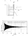
- the multi-dimensional vibration control method of the strut tail-supported aircraft model is evaluated by the acceleration data measured by the pitch acceleration sensor 6 and the yaw acceleration sensor 7. As shown in FIG. 6 , when the pitching direction is hammered, the multi-dimensional vibration control method of the strut tail-supported aircraft model is not used, and the vibration attenuation time of the aircraft model 5 in the pitching direction is 21.49s. After using the multi-dimensional vibration control method of the strut tail-supported aircraft model, the vibration attenuation time of aircraft model 5 in pitch direction is 1.22s, and the vibration in pitch direction can be controlled effectively. As shown in FIG.
- the multi-dimensional vibration control method of the strut tail-supported aircraft model when hammering in the yaw direction, the multi-dimensional vibration control method of the strut tail-supported aircraft model is not used, and the vibration attenuation time of the aircraft model 5 in the yaw direction is 10.45s.
- the attenuation time of the yaw direction vibration of the aircraft model 5 is 1.23s, and the yaw direction vibration can be effectively controlled. As shown in FIG.
- the vibration attenuation time of the aircraft model 5 in the pitching direction is 18.85s
- the yaw direction vibration attenuation time is 11.35s.
- the vibration attenuation time of the aircraft model 5 in the pitching direction is 1.03s
- the attenuation time of the yaw vibration is 0.98 s. The results show that the vibration of the aircraft model in any direction can be effectively controlled.
Landscapes
- Physics & Mathematics (AREA)
- General Physics & Mathematics (AREA)
- Fluid Mechanics (AREA)
- Engineering & Computer Science (AREA)
- Manufacturing & Machinery (AREA)
- Transportation (AREA)
- Aviation & Aerospace Engineering (AREA)
- Aerodynamic Tests, Hydrodynamic Tests, Wind Tunnels, And Water Tanks (AREA)
- Vibration Prevention Devices (AREA)
Claims (2)
- Procédé de commande de vibration multidimensionnelle pour un modèle d'aéronef à jambe supportée par la queue, dans lequel le procédé est réalisé par la disposition de capteurs d'accélération de tangage et de lacet sur le centre de masse du modèle d'aéronef, mesurant les composantes de tangage et de lacet d'accélération de vibration principale du modèle d'aéronef à l'aide des capteurs d'accélération de tangage et de lacet, caractérisé ence que le procédé comprend les étapes suivantes : le calcul du vecteur de vibration principale et la détermination du plan de vibration en temps réel de la jambe, l'introduction d'une force d'inertie pour résoudre l'amortisseur de vibration multidimensionnelle sur la section active par moment de flexion dynamique, puis l'obtention de la distribution de contrainte d'initiation sur la section active, à travers la relation de position spatiale du plan de vibration en temps réel de l'amortisseur de vibration multidimensionnelle pour participer au travail de numéro de série de l'actionneur en céramique piézoélectrique ;le calcul de la force de commande de vibration en temps réel en fonction de la contrainte sur la section active de l'actionneur en céramique piézoélectrique, puis le moment de flexion dynamique est généré dans le processus du moment de flexion inverse résistant à la vibration du modèle d'aéronef ; le système de commande actif de vibration multidimensionnelle basé sur un actionneur en céramique piézoélectrique est adopté pour commander la vibration multidimensionnelle ; et dans lequel le procédé comprend les étapes spécifiques suivantes :étape 1 : établir un système de coordonnées absolues du système de support de modèle d'aéronef
le système de coordonnées absolues OXYZ (E) est établi sur un monopode d'aéronef (4), et l'origine des coordonnées est établie dans la position d'équilibre à l'intersection de la section active (F) et de l'axe du monopode d'aéronef (4), qui est défini comme O ; la direction de l'axe X coïncide avec la position d'équilibre de l'axe du monopode de l'aéronef (4) et pointe vers le modèle d'aéronef (5), la direction de l'axe Y est que l'intersection de la section active (F) et le plan de tangage pointe vers le haut ; l'axe Z est déterminé par la manipulation correcte ; un système de coordonnées de mesure de vibrations OAXAYAZA (A) est établi sur le modèle d'aéronef (5), dont l'origine est établie à l'intersection du centre de masse du modèle d'aéronef (5) et de l'axe X du système de coordonnées absolues OXYZ (E), qui est défini comme étant la direction de l'OA ; l'axe de coordonnées XA coïncide avec l'axe X du système de coordonnées absolues OXYZ (E), l'axe de coordonnées YA et l'axe Y du système de coordonnées absolues OXYZ (E) pointent vers le haut, et l'axe de coordonnées ZA est déterminé par la manipulation correcte ;étape 2 : calculer des composantes de l'accélération de vibration principale dans le plan de tangage et le plan de lacet en temps réel
à l'aide d'un accéléromètre de tangage (6) et d'un accéléromètre de lacet (7) au centre de masse du modèle d'aéronef (5) pour mesurer l'accélération de la vibration principale dans le plan de tangage et le plan de lacet perpendiculaires l'un à l'autre, l'accélération de la vibration principale est renvoyée au dispositif de commande en temps réel (8) commandé par l'ordinateur (9), et une pluralité de valeurs d'échantillonnage d'accélération du plan de tangage et du plan de lacet sont collectées dans chaque cycle de commande de vibration, les composantes d'accélération de l'accélération de vibration principale dans la direction du tangage et la direction du lacet dans un cycle de commande de vibration sont calculées respectivement par les formules (1) et (2) :
 étape 3 : résoudre le vecteur d'accélération de vibration principal en temps réel
l'accélération de vibration principale est obtenue en combinant les composantes d'accélération dans la direction de tangage et la direction de lacet ; l'accélération de vibration principale consiste en l'amplitude et la direction ; le vecteur d'accélération de vibration principale est construit en résolvant l'amplitude et la direction du vecteur d'accélération de vibration principale dans chaque cycle de commande de vibration en temps réel à l'aide des formules (3) et (4) :
 étape 4 : établir un système de coordonnées de commande active de vibration en temps réel du modèle d'aéronef et déterminer le plan de vibration en temps réel de la jambe
le système de coordonnées de commande de vibration active en temps réel OαXαYαZα (D) est établi sur la section active (F), et son origine coïncide avec l'origine O du système de coordonnées absolues OXYZ (E) ; il est défini que la direction du Oα ; l'axe Xα coïncide avec la direction de la coordonnée X de la coordonnée absolue OXYZ (E), l'axe Yα coïncide avec la a(t) direction du vecteur d'accélération de vibration principale et l'axe de coordonnée Z α est déterminé par la manipulation correcte ; le plan XαOαYα est le plan de vibration en temps réel XαOαYα (C) de la jambe ; en raison du caractère aléatoire de la vibration du modèle d'aéronef (5), le système de coordonnées de commande de vibration active en temps réel OαXαYαZα (D) change avec le temps, et le plan de vibration en temps réel XαOαYα (C) change avec le temps ;étape 5 : la force d'inertie en temps réel et la distribution de contraintes sur la section active du système de support sont résolues
sur le plan de vibration en temps réel XαOαYα (C) du monopode d'aéronef (4), la force d'inertie est résolue en temps réel par la formule (5)


α (t) est le moment d'inertie en temps réel de la section active (F) par rapport à l'axe de coordonnées Zα ;étape 6 : déterminer le numéro de série de l'actionneur piézoélectrique en temps réel et calculer la force de commande de vibration
un certain nombre d'actionneurs en céramique piézoélectriques (3-1) sont disposés uniformément dans la direction circonférentielle de l'amortisseur de vibration multidimensionnelle (3) au niveau de la section active (F), le rayon circonférentiel uniformément réparti est R, et la céramique piézoélectrique qui coïncide avec l'axe Z du système de coordonnées absolues, OXYZ (E) est défini comme actionneur piézoélectrique en céramique n° 0 (3-1), l'actionneur piézoélectrique en céramique n° 1 (3-1), l'actionneur en céramique piézoélectrique n° 2 (3-1), ..., l'actionneur en céramique piézoélectrique n° n (3-1), sont disposés à leur tour dans un réseau circulaire dans le sens anti-horaire ; l'angle de réseau entre les deux actionneurs piézoélectriques en céramique adjacents (3-1) est


c est l'angle entre l'actionneur en céramique piézoélectrique participant (3-1) et la direction de l'axe Z du système de coordonnées absolues OXYZ (E), et la force résultante sur la section active (F) de l'actionneur en céramique piézoélectrique participant (3-1) est :
c est la zone de contact entre l'actionneur céramique piézoélectrique no. nc participant (3-1) et la section active (F), et la force de résistance requise par l'actionneur céramique piézoélectrique no. nc participant (3-1) est :
- Procédé de commande de vibration multidimensionnelle d'un modèle d'aéronef supporté par la de jambe supportée par la queue selon la revendication 1, dans lequel le procédé de commande de vibration multidimensionnelle pour le modèle de l'aéronef contreventé par le monopode adopte un système de commande active de vibration multidimensionnelle, qui se compose principalement d'un capteur d'accélération de tangage (6), d'un capteur d'accélération de lacet (7), d'un dispositif de commande en temps réel (8), d'un ordinateur (9), d'un groupe d'amplificateurs de puissance d'actionneur en céramique piézoélectrique (10) et d'un amortisseur de vibration multidimensionnelle (3) ; le capteur d'accélération de tangage (6) est installé dans le centre de masse du modèle d'aéronef (5) dans le plan de tangage et est utilisé pour mesurer la composante d'accélération de vibration de la vibration principale du modèle d'aéronef (5) dans le plan de tangage ; le capteur d'accélération de lacet (7) est installé dans le centre de masse du modèle d'aéronef (5) dans le plan de lacet et est utilisé pour mesurer la composante d'accélération de vibration de la vibration principale du modèle d'aéronef (5) dans le plan de lacet ; l'amortisseur de vibration multidimensionnelle (3) comporte une pluralité d'actionneurs en céramique piézoélectriques uniformément répartis (3-1), dont chacun est préserré par un mécanisme de pré-serrage (3-2), respectivement, pour assurer la sortie fiable de la force dynamique de l'actionneur piézoélectrique en céramique (3-1) ; l'amortisseur de vibration multidimensionnelle (3) est installé dans le plan de vibration en temps réel XαOαYα (C) du monopode de l'aéronef (4), le dispositif de commande en temps réel (8) est connecté à l'ordinateur (9), et l'ordinateur (9) est utilisé pour commander le dispositif de commande en temps réel (8) et surveiller le processus de commande de vibration ; le dispositif de commande en temps réel (8) est connecté au capteur d'accélération de tangage (6) et au capteur d'accélération de lacet (7) respectivement pour obtenir les composantes d'accélération de vibration dans le plan de tangage et le plan de lacet du modèle d'aéronef (5) en réel le temps ; le dispositif de commande en temps réel (8) est connecté à un groupe d'amplificateurs de puissance d'actionneur en céramique piézoélectrique (10), et une pluralité d'amplificateurs de puissance d'actionneur en céramique piézoélectrique (10-1) dans le groupe d'amplificateurs de puissance d'actionneur en céramique piézoélectrique (10) sont respectivement connectés à une pluralité d'actionneurs piézoélectriques en céramique (3-1) dans l'amortisseur de vibration multidimensionnelle (3).
Applications Claiming Priority (2)
| Application Number | Priority Date | Filing Date | Title |
|---|---|---|---|
| CN201811545677.8A CN109668710B (zh) | 2018-12-18 | 2018-12-18 | 支杆尾撑式飞行器模型多维振动控制方法 |
| PCT/CN2019/106886 WO2020125109A1 (fr) | 2018-12-18 | 2019-09-20 | Procédé de commande de vibration multidimensionnel pour un modèle d'aéronef monté sur une balance-dard |
Publications (3)
| Publication Number | Publication Date |
|---|---|
| EP3770575A4 EP3770575A4 (fr) | 2021-01-27 |
| EP3770575A1 EP3770575A1 (fr) | 2021-01-27 |
| EP3770575B1 true EP3770575B1 (fr) | 2021-09-08 |
Family
ID=66143808
Family Applications (1)
| Application Number | Title | Priority Date | Filing Date |
|---|---|---|---|
| EP19877532.2A Not-in-force EP3770575B1 (fr) | 2018-12-18 | 2019-09-20 | Procédé de commande de vibration multidimensionnel pour un modèle d'aéronef monté sur une balance-dard |
Country Status (4)
| Country | Link |
|---|---|
| US (1) | US10969298B2 (fr) |
| EP (1) | EP3770575B1 (fr) |
| CN (1) | CN109668710B (fr) |
| WO (1) | WO2020125109A1 (fr) |
Cited By (1)
| Publication number | Priority date | Publication date | Assignee | Title |
|---|---|---|---|---|
| EP4592661A1 (fr) * | 2024-01-29 | 2025-07-30 | Deutsches Zentrum für Luft- und Raumfahrt e.V. | Dispositif de test de soufflerie pour déterminer des valeurs de contribution dynamiques sur un modèle de soufflerie |
Families Citing this family (24)
| Publication number | Priority date | Publication date | Assignee | Title |
|---|---|---|---|---|
| CN109668710B (zh) * | 2018-12-18 | 2020-04-07 | 大连理工大学 | 支杆尾撑式飞行器模型多维振动控制方法 |
| CN110907128A (zh) * | 2019-12-26 | 2020-03-24 | 中国空气动力研究与发展中心高速空气动力研究所 | 风洞模型抑振装置及系统 |
| CN112033636B (zh) * | 2020-08-06 | 2021-06-18 | 大连理工大学 | 一种飞行器模型随机多维振动的降维监测方法 |
| CN111929023B (zh) * | 2020-08-11 | 2021-08-06 | 日照坤仑智能科技有限公司 | 风洞中飞行器模型驱动系统及性能测量方法 |
| CN113203538B (zh) * | 2021-05-25 | 2022-09-13 | 中国航空工业集团公司哈尔滨空气动力研究所 | 一种抑制镜像支杆振动的装置 |
| CN113252285B (zh) * | 2021-07-15 | 2021-10-08 | 中国空气动力研究与发展中心低速空气动力研究所 | 一种立式风洞模型俯仰-翻滚试验装置及使用方法 |
| CN113776654A (zh) * | 2021-09-15 | 2021-12-10 | 航天时代飞鹏有限公司 | 一种机翼单点失效结构健康监测方法 |
| CN114112291B (zh) * | 2021-11-15 | 2022-08-09 | 大连理工大学 | 一种模型适应型振动主动抑制方法 |
| CN114112283B (zh) * | 2021-12-01 | 2023-05-23 | 中国空气动力研究与发展中心低速空气动力研究所 | 一种涡桨运输机动力增升全模风洞试验方法 |
| CN114323549A (zh) * | 2021-12-14 | 2022-04-12 | 大连理工大学 | 一种风洞模型振动惯性作动抑制装置 |
| CN114486154B (zh) * | 2021-12-28 | 2024-11-29 | 中国航天空气动力技术研究院 | 一种两自由度翼段支撑装置及风洞试验设备 |
| CN115014697B (zh) * | 2022-05-31 | 2026-01-30 | 成都流体动力创新中心 | 一种磁浮飞行风洞气动力间接测量方法 |
| CN115196040B (zh) * | 2022-07-25 | 2025-06-27 | 中国航空工业集团公司哈尔滨空气动力研究所 | 开口大迎角试验系统支架干扰柔性测量装置 |
| CN114993603B (zh) * | 2022-08-02 | 2022-09-30 | 中国航空工业集团公司沈阳空气动力研究所 | 大展弦比模型纵向振动前后减振器配合控制方法及系统 |
| CN115112340B (zh) * | 2022-08-29 | 2022-11-15 | 中国航空工业集团公司沈阳空气动力研究所 | 一种侧滑试验前后置减振器多自由度振动解耦控制方法 |
| CN115373362B (zh) * | 2022-10-24 | 2023-01-24 | 中国空气动力研究与发展中心高速空气动力研究所 | 一种针对多执行机构的协同控制策略 |
| CN115933362B (zh) * | 2022-11-04 | 2025-12-16 | 中国空气动力研究与发展中心高速空气动力研究所 | 风洞试验减震装置的控制方法、装置、设备及介质 |
| CN116358822B (zh) * | 2023-03-28 | 2025-08-19 | 中国空气动力研究与发展中心超高速空气动力研究所 | 一种模型测力系统动态标定方法及设备 |
| CN116593108B (zh) * | 2023-04-28 | 2025-08-15 | 西安交通大学 | 一种模拟卫星平台振动主动控制实验装置及使用方法 |
| CN116952524B (zh) * | 2023-09-18 | 2023-12-05 | 中国航空工业集团公司沈阳空气动力研究所 | 一种高速风洞动导数试验监测方法、电子设备及存储介质 |
| CN117291105A (zh) * | 2023-10-10 | 2023-12-26 | 太原科技大学 | 起重机金属结构的动应力预测方法、装置、设备及介质 |
| CN119164598B (zh) * | 2024-11-21 | 2025-01-28 | 大连理工大学 | 一种基于压电驱动的尾撑式腔内高频强迫振动动导数试验方法 |
| CN119389454B (zh) * | 2025-01-02 | 2025-03-11 | 北京航宇振控科技有限责任公司 | 飞机振动模拟装置及方法 |
| CN119758849B (zh) * | 2025-03-05 | 2025-05-13 | 大连理工大学 | 一种风洞模型支撑系统多维振动实时控制方法 |
Family Cites Families (23)
| Publication number | Priority date | Publication date | Assignee | Title |
|---|---|---|---|---|
| US7395727B2 (en) * | 2004-07-28 | 2008-07-08 | Omniprobe, Inc. | Strain detection for automated nano-manipulation |
| CN102353513B (zh) * | 2011-08-31 | 2013-07-10 | 中国航天空气动力技术研究院 | 一种可变体飞行器气动测试系统 |
| KR20140024109A (ko) * | 2012-08-20 | 2014-02-28 | 한국항공우주산업 주식회사 | T-50 항공기의 버펫 특성 개선 방법 |
| US9354134B2 (en) * | 2013-03-08 | 2016-05-31 | The United States Of America As Represented By The Administrator Of The National Aeronautics And Space Adminstration | In-situ load system for calibrating and validating aerodynamic properties of scaled aircraft in ground-based aerospace testing applications |
| DE102013213675A1 (de) * | 2013-07-12 | 2015-01-15 | Airbus Operations Gmbh | Windkanalwaage und System mit Flügelmodell und Windkanalwaage |
| CN106441779B (zh) * | 2015-08-06 | 2019-03-01 | 日照坤仑智能科技有限公司 | 一种高速风洞中测量飞行器三自由度动稳定参数的装置 |
| CN105258916B (zh) * | 2015-11-18 | 2017-09-01 | 中国空气动力研究与发展中心高速空气动力研究所 | 一种高速风洞模型后体畸变对横航向气动特性影响的修正方法 |
| US10060823B2 (en) * | 2016-02-19 | 2018-08-28 | The Boeing Company | Miniaturized tuned mass damper for application to high speed wind tunnel testing |
| CN105784318B (zh) * | 2016-03-04 | 2017-07-18 | 中国空气动力研究与发展中心低速空气动力研究所 | 一种低速风洞模型飞行实验系统及方法 |
| CN105868535B (zh) * | 2016-03-24 | 2018-02-16 | 大连理工大学 | 风洞模型支杆抑振系统作动器布局优化方法 |
| US11131598B2 (en) * | 2016-08-04 | 2021-09-28 | Ahmad D. Vakili | Technology to control a model and balance support system's dynamics and isolate the balance as needed to increase test facilities productivity |
| US10656048B2 (en) * | 2017-03-30 | 2020-05-19 | The Boeing Company | Remotely controlled methods and systems for actuating boundary layer transition devices in a wind tunnel model |
| US10267708B2 (en) * | 2017-05-18 | 2019-04-23 | The Boeing Company | Wind tunnel balance and method of use |
| CN107314883B (zh) * | 2017-06-23 | 2019-02-01 | 大连理工大学 | 一种风洞模型振动的风载自减振方法 |
| CN207050948U (zh) | 2017-07-13 | 2018-02-27 | 南京航空航天大学 | 一种含柔性铰链可实现振动主动控制的风洞用尾支杆 |
| CN107462394B (zh) * | 2017-07-24 | 2019-04-16 | 大连理工大学 | 基于平滑预测策略的多传感器风洞支杆抑振方法 |
| CN107860550A (zh) * | 2017-10-23 | 2018-03-30 | 中国科学院力学研究所 | 一种用于风洞实验中飞行器模型的支撑方法 |
| CN108132134A (zh) * | 2017-11-15 | 2018-06-08 | 南京航空航天大学 | 基于风洞自由飞试验的气动导数辨识方法和系统 |
| CN108132133A (zh) * | 2017-12-04 | 2018-06-08 | 中国航空工业集团公司北京长城计量测试技术研究所 | 一种组合式多分量扑翼飞行器机翼气动特性测试方法 |
| CN108225714A (zh) | 2018-02-02 | 2018-06-29 | 哈尔滨工程大学 | 一种应用于风洞模型振动抑制的主动抑振装置 |
| CN108227728B (zh) * | 2018-03-29 | 2020-01-10 | 北京航空航天大学 | 一种考虑混合执行机构切换的航天器姿态动态控制分配方法 |
| CN108871724B (zh) * | 2018-05-03 | 2019-08-09 | 大连理工大学 | 一种振动模拟系统的随机振动模拟方法 |
| CN109668710B (zh) * | 2018-12-18 | 2020-04-07 | 大连理工大学 | 支杆尾撑式飞行器模型多维振动控制方法 |
-
2018
- 2018-12-18 CN CN201811545677.8A patent/CN109668710B/zh active Active
-
2019
- 2019-09-20 WO PCT/CN2019/106886 patent/WO2020125109A1/fr not_active Ceased
- 2019-09-20 EP EP19877532.2A patent/EP3770575B1/fr not_active Not-in-force
- 2019-09-20 US US16/761,778 patent/US10969298B2/en active Active
Cited By (1)
| Publication number | Priority date | Publication date | Assignee | Title |
|---|---|---|---|---|
| EP4592661A1 (fr) * | 2024-01-29 | 2025-07-30 | Deutsches Zentrum für Luft- und Raumfahrt e.V. | Dispositif de test de soufflerie pour déterminer des valeurs de contribution dynamiques sur un modèle de soufflerie |
Also Published As
| Publication number | Publication date |
|---|---|
| EP3770575A4 (fr) | 2021-01-27 |
| EP3770575A1 (fr) | 2021-01-27 |
| CN109668710B (zh) | 2020-04-07 |
| WO2020125109A1 (fr) | 2020-06-25 |
| US10969298B2 (en) | 2021-04-06 |
| US20200393327A1 (en) | 2020-12-17 |
| CN109668710A (zh) | 2019-04-23 |
Similar Documents
| Publication | Publication Date | Title |
|---|---|---|
| EP3770575B1 (fr) | Procédé de commande de vibration multidimensionnel pour un modèle d'aéronef monté sur une balance-dard | |
| Lee et al. | Suppressing aeroelastic instability using broadband passive targeted energy transfers, part 2: experiments | |
| CN105868535B (zh) | 风洞模型支杆抑振系统作动器布局优化方法 | |
| Wu et al. | Studies on aeroservoelasticity semi-physical simulation test for missiles | |
| Wang et al. | Flutter control of active aerodynamic flaps mounted on streamlined bridge deck fairing edges: an experimental study | |
| Rivers et al. | NASA common research model test envelope extension with active sting damping at NTF | |
| CN108106952A (zh) | 一种梁的双对称截面冲击载荷测量方法 | |
| Li et al. | Dual-track nonlinear energy sinks for mitigating bi-directional vibration of wind turbine towers in typhoons | |
| Chen et al. | Analysis of flutter and nonlinear dynamics of a composite laminated plate | |
| CN112067249A (zh) | 一种带有阻力舵的长直翼动力学耦合风洞试验模型 | |
| CN113971346B (zh) | 一种考虑非线性跳变响应的高低周复合疲劳寿命预估方法 | |
| CN106768791A (zh) | 一种微量风洞天平 | |
| Li et al. | Dynamic Inverse Analysis of Steel–Concrete Hybrid Wind Turbine Tower | |
| Cooper et al. | Wind tunnel testing of a high aspect ratio wing model | |
| Gordnier et al. | Physical mechanisms for limit-cycle oscillations of a cropped delta wing | |
| CN113218615A (zh) | 一种分布式气动力与有限激振点激振载荷的等效方法 | |
| Brito et al. | Aerodynamic instability of cylindrical bluff bodies in non-homogeneous flow | |
| CN107314883A (zh) | 一种风洞模型振动的风载自减振方法 | |
| Yuan et al. | Transient dynamics simulation of helicopter tail transmission shaft damage | |
| Zaracho et al. | Wind loading and response of solar tracker arrays | |
| Harash et al. | Nonlinear bending-torsion flutter experiments of a medium-aspect-ratio flexible wing model | |
| De Marqui Junior et al. | Design of an experimental flutter mount system | |
| Magill | Design of a wire suspension system for dynamic testing in AEDC 16T | |
| Liu et al. | Numerical Simulation of Hypersonic Dynamic Stability Parameters: 7 Degrees Blunt Cone Mode Dynamic Derivative Supported Interference | |
| Kumar et al. | Parametric study on impact of delamination on flutter velocity of wind turbine blade structure |
Legal Events
| Date | Code | Title | Description |
|---|---|---|---|
| STAA | Information on the status of an ep patent application or granted ep patent |
Free format text: STATUS: UNKNOWN |
|
| STAA | Information on the status of an ep patent application or granted ep patent |
Free format text: STATUS: THE INTERNATIONAL PUBLICATION HAS BEEN MADE |
|
| PUAI | Public reference made under article 153(3) epc to a published international application that has entered the european phase |
Free format text: ORIGINAL CODE: 0009012 |
|
| STAA | Information on the status of an ep patent application or granted ep patent |
Free format text: STATUS: REQUEST FOR EXAMINATION WAS MADE |
|
| 17P | Request for examination filed |
Effective date: 20200505 |
|
| A4 | Supplementary search report drawn up and despatched |
Effective date: 20201203 |
|
| AK | Designated contracting states |
Kind code of ref document: A1 Designated state(s): AL AT BE BG CH CY CZ DE DK EE ES FI FR GB GR HR HU IE IS IT LI LT LU LV MC MK MT NL NO PL PT RO RS SE SI SK SM TR |
|
| AX | Request for extension of the european patent |
Extension state: BA ME |
|
| STAA | Information on the status of an ep patent application or granted ep patent |
Free format text: STATUS: EXAMINATION IS IN PROGRESS |
|
| 17Q | First examination report despatched |
Effective date: 20210217 |
|
| GRAP | Despatch of communication of intention to grant a patent |
Free format text: ORIGINAL CODE: EPIDOSNIGR1 |
|
| STAA | Information on the status of an ep patent application or granted ep patent |
Free format text: STATUS: GRANT OF PATENT IS INTENDED |
|
| DAV | Request for validation of the european patent (deleted) | ||
| DAX | Request for extension of the european patent (deleted) | ||
| INTG | Intention to grant announced |
Effective date: 20210519 |
|
| GRAS | Grant fee paid |
Free format text: ORIGINAL CODE: EPIDOSNIGR3 |
|
| GRAA | (expected) grant |
Free format text: ORIGINAL CODE: 0009210 |
|
| STAA | Information on the status of an ep patent application or granted ep patent |
Free format text: STATUS: THE PATENT HAS BEEN GRANTED |
|
| AK | Designated contracting states |
Kind code of ref document: B1 Designated state(s): AL AT BE BG CH CY CZ DE DK EE ES FI FR GB GR HR HU IE IS IT LI LT LU LV MC MK MT NL NO PL PT RO RS SE SI SK SM TR |
|
| REG | Reference to a national code |
Ref country code: GB Ref legal event code: FG4D |
|
| REG | Reference to a national code |
Ref country code: CH Ref legal event code: EP Ref country code: AT Ref legal event code: REF Ref document number: 1428994 Country of ref document: AT Kind code of ref document: T Effective date: 20210915 |
|
| REG | Reference to a national code |
Ref country code: IE Ref legal event code: FG4D |
|
| REG | Reference to a national code |
Ref country code: DE Ref legal event code: R096 Ref document number: 602019007596 Country of ref document: DE |
|
| PGFP | Annual fee paid to national office [announced via postgrant information from national office to epo] |
Ref country code: DE Payment date: 20210920 Year of fee payment: 3 |
|
| REG | Reference to a national code |
Ref country code: LT Ref legal event code: MG9D |
|
| REG | Reference to a national code |
Ref country code: NL Ref legal event code: MP Effective date: 20210908 |
|
| PG25 | Lapsed in a contracting state [announced via postgrant information from national office to epo] |
Ref country code: SE Free format text: LAPSE BECAUSE OF FAILURE TO SUBMIT A TRANSLATION OF THE DESCRIPTION OR TO PAY THE FEE WITHIN THE PRESCRIBED TIME-LIMIT Effective date: 20210908 Ref country code: RS Free format text: LAPSE BECAUSE OF FAILURE TO SUBMIT A TRANSLATION OF THE DESCRIPTION OR TO PAY THE FEE WITHIN THE PRESCRIBED TIME-LIMIT Effective date: 20210908 Ref country code: ES Free format text: LAPSE BECAUSE OF FAILURE TO SUBMIT A TRANSLATION OF THE DESCRIPTION OR TO PAY THE FEE WITHIN THE PRESCRIBED TIME-LIMIT Effective date: 20210908 Ref country code: BG Free format text: LAPSE BECAUSE OF FAILURE TO SUBMIT A TRANSLATION OF THE DESCRIPTION OR TO PAY THE FEE WITHIN THE PRESCRIBED TIME-LIMIT Effective date: 20211208 Ref country code: LT Free format text: LAPSE BECAUSE OF FAILURE TO SUBMIT A TRANSLATION OF THE DESCRIPTION OR TO PAY THE FEE WITHIN THE PRESCRIBED TIME-LIMIT Effective date: 20210908 Ref country code: NO Free format text: LAPSE BECAUSE OF FAILURE TO SUBMIT A TRANSLATION OF THE DESCRIPTION OR TO PAY THE FEE WITHIN THE PRESCRIBED TIME-LIMIT Effective date: 20211208 Ref country code: HR Free format text: LAPSE BECAUSE OF FAILURE TO SUBMIT A TRANSLATION OF THE DESCRIPTION OR TO PAY THE FEE WITHIN THE PRESCRIBED TIME-LIMIT Effective date: 20210908 Ref country code: FI Free format text: LAPSE BECAUSE OF FAILURE TO SUBMIT A TRANSLATION OF THE DESCRIPTION OR TO PAY THE FEE WITHIN THE PRESCRIBED TIME-LIMIT Effective date: 20210908 |
|
| REG | Reference to a national code |
Ref country code: AT Ref legal event code: MK05 Ref document number: 1428994 Country of ref document: AT Kind code of ref document: T Effective date: 20210908 |
|
| PG25 | Lapsed in a contracting state [announced via postgrant information from national office to epo] |
Ref country code: LV Free format text: LAPSE BECAUSE OF FAILURE TO SUBMIT A TRANSLATION OF THE DESCRIPTION OR TO PAY THE FEE WITHIN THE PRESCRIBED TIME-LIMIT Effective date: 20210908 Ref country code: GR Free format text: LAPSE BECAUSE OF FAILURE TO SUBMIT A TRANSLATION OF THE DESCRIPTION OR TO PAY THE FEE WITHIN THE PRESCRIBED TIME-LIMIT Effective date: 20211209 |
|
| PG25 | Lapsed in a contracting state [announced via postgrant information from national office to epo] |
Ref country code: AT Free format text: LAPSE BECAUSE OF FAILURE TO SUBMIT A TRANSLATION OF THE DESCRIPTION OR TO PAY THE FEE WITHIN THE PRESCRIBED TIME-LIMIT Effective date: 20210908 |
|
| REG | Reference to a national code |
Ref country code: BE Ref legal event code: MM Effective date: 20210930 |
|
| PG25 | Lapsed in a contracting state [announced via postgrant information from national office to epo] |
Ref country code: IS Free format text: LAPSE BECAUSE OF FAILURE TO SUBMIT A TRANSLATION OF THE DESCRIPTION OR TO PAY THE FEE WITHIN THE PRESCRIBED TIME-LIMIT Effective date: 20220108 Ref country code: SM Free format text: LAPSE BECAUSE OF FAILURE TO SUBMIT A TRANSLATION OF THE DESCRIPTION OR TO PAY THE FEE WITHIN THE PRESCRIBED TIME-LIMIT Effective date: 20210908 Ref country code: SK Free format text: LAPSE BECAUSE OF FAILURE TO SUBMIT A TRANSLATION OF THE DESCRIPTION OR TO PAY THE FEE WITHIN THE PRESCRIBED TIME-LIMIT Effective date: 20210908 Ref country code: RO Free format text: LAPSE BECAUSE OF FAILURE TO SUBMIT A TRANSLATION OF THE DESCRIPTION OR TO PAY THE FEE WITHIN THE PRESCRIBED TIME-LIMIT Effective date: 20210908 Ref country code: PT Free format text: LAPSE BECAUSE OF FAILURE TO SUBMIT A TRANSLATION OF THE DESCRIPTION OR TO PAY THE FEE WITHIN THE PRESCRIBED TIME-LIMIT Effective date: 20220110 Ref country code: PL Free format text: LAPSE BECAUSE OF FAILURE TO SUBMIT A TRANSLATION OF THE DESCRIPTION OR TO PAY THE FEE WITHIN THE PRESCRIBED TIME-LIMIT Effective date: 20210908 Ref country code: NL Free format text: LAPSE BECAUSE OF FAILURE TO SUBMIT A TRANSLATION OF THE DESCRIPTION OR TO PAY THE FEE WITHIN THE PRESCRIBED TIME-LIMIT Effective date: 20210908 Ref country code: EE Free format text: LAPSE BECAUSE OF FAILURE TO SUBMIT A TRANSLATION OF THE DESCRIPTION OR TO PAY THE FEE WITHIN THE PRESCRIBED TIME-LIMIT Effective date: 20210908 Ref country code: CZ Free format text: LAPSE BECAUSE OF FAILURE TO SUBMIT A TRANSLATION OF THE DESCRIPTION OR TO PAY THE FEE WITHIN THE PRESCRIBED TIME-LIMIT Effective date: 20210908 Ref country code: AL Free format text: LAPSE BECAUSE OF FAILURE TO SUBMIT A TRANSLATION OF THE DESCRIPTION OR TO PAY THE FEE WITHIN THE PRESCRIBED TIME-LIMIT Effective date: 20210908 |
|
| REG | Reference to a national code |
Ref country code: DE Ref legal event code: R097 Ref document number: 602019007596 Country of ref document: DE |
|
| PG25 | Lapsed in a contracting state [announced via postgrant information from national office to epo] |
Ref country code: MC Free format text: LAPSE BECAUSE OF FAILURE TO SUBMIT A TRANSLATION OF THE DESCRIPTION OR TO PAY THE FEE WITHIN THE PRESCRIBED TIME-LIMIT Effective date: 20210908 |
|
| PLBE | No opposition filed within time limit |
Free format text: ORIGINAL CODE: 0009261 |
|
| STAA | Information on the status of an ep patent application or granted ep patent |
Free format text: STATUS: NO OPPOSITION FILED WITHIN TIME LIMIT |
|
| PG25 | Lapsed in a contracting state [announced via postgrant information from national office to epo] |
Ref country code: LU Free format text: LAPSE BECAUSE OF NON-PAYMENT OF DUE FEES Effective date: 20210920 Ref country code: IE Free format text: LAPSE BECAUSE OF NON-PAYMENT OF DUE FEES Effective date: 20210920 Ref country code: DK Free format text: LAPSE BECAUSE OF FAILURE TO SUBMIT A TRANSLATION OF THE DESCRIPTION OR TO PAY THE FEE WITHIN THE PRESCRIBED TIME-LIMIT Effective date: 20210908 Ref country code: BE Free format text: LAPSE BECAUSE OF NON-PAYMENT OF DUE FEES Effective date: 20210930 |
|
| 26N | No opposition filed |
Effective date: 20220609 |
|
| PG25 | Lapsed in a contracting state [announced via postgrant information from national office to epo] |
Ref country code: FR Free format text: LAPSE BECAUSE OF NON-PAYMENT OF DUE FEES Effective date: 20211108 |
|
| PG25 | Lapsed in a contracting state [announced via postgrant information from national office to epo] |
Ref country code: IT Free format text: LAPSE BECAUSE OF FAILURE TO SUBMIT A TRANSLATION OF THE DESCRIPTION OR TO PAY THE FEE WITHIN THE PRESCRIBED TIME-LIMIT Effective date: 20210908 |
|
| REG | Reference to a national code |
Ref country code: DE Ref legal event code: R119 Ref document number: 602019007596 Country of ref document: DE |
|
| REG | Reference to a national code |
Ref country code: CH Ref legal event code: PL |
|
| PG25 | Lapsed in a contracting state [announced via postgrant information from national office to epo] |
Ref country code: CY Free format text: LAPSE BECAUSE OF FAILURE TO SUBMIT A TRANSLATION OF THE DESCRIPTION OR TO PAY THE FEE WITHIN THE PRESCRIBED TIME-LIMIT Effective date: 20210908 |
|
| PG25 | Lapsed in a contracting state [announced via postgrant information from national office to epo] |
Ref country code: LI Free format text: LAPSE BECAUSE OF NON-PAYMENT OF DUE FEES Effective date: 20220930 Ref country code: HU Free format text: LAPSE BECAUSE OF FAILURE TO SUBMIT A TRANSLATION OF THE DESCRIPTION OR TO PAY THE FEE WITHIN THE PRESCRIBED TIME-LIMIT; INVALID AB INITIO Effective date: 20190920 Ref country code: DE Free format text: LAPSE BECAUSE OF NON-PAYMENT OF DUE FEES Effective date: 20230401 Ref country code: CH Free format text: LAPSE BECAUSE OF NON-PAYMENT OF DUE FEES Effective date: 20220930 |
|
| PG25 | Lapsed in a contracting state [announced via postgrant information from national office to epo] |
Ref country code: SI Free format text: LAPSE BECAUSE OF FAILURE TO SUBMIT A TRANSLATION OF THE DESCRIPTION OR TO PAY THE FEE WITHIN THE PRESCRIBED TIME-LIMIT Effective date: 20210908 |
|
| PG25 | Lapsed in a contracting state [announced via postgrant information from national office to epo] |
Ref country code: MK Free format text: LAPSE BECAUSE OF FAILURE TO SUBMIT A TRANSLATION OF THE DESCRIPTION OR TO PAY THE FEE WITHIN THE PRESCRIBED TIME-LIMIT Effective date: 20210908 |
|
| GBPC | Gb: european patent ceased through non-payment of renewal fee |
Effective date: 20230920 |
|
| PG25 | Lapsed in a contracting state [announced via postgrant information from national office to epo] |
Ref country code: GB Free format text: LAPSE BECAUSE OF NON-PAYMENT OF DUE FEES Effective date: 20230920 |
|
| PG25 | Lapsed in a contracting state [announced via postgrant information from national office to epo] |
Ref country code: GB Free format text: LAPSE BECAUSE OF NON-PAYMENT OF DUE FEES Effective date: 20230920 |
|
| PG25 | Lapsed in a contracting state [announced via postgrant information from national office to epo] |
Ref country code: MT Free format text: LAPSE BECAUSE OF FAILURE TO SUBMIT A TRANSLATION OF THE DESCRIPTION OR TO PAY THE FEE WITHIN THE PRESCRIBED TIME-LIMIT Effective date: 20210908 |
|
| PG25 | Lapsed in a contracting state [announced via postgrant information from national office to epo] |
Ref country code: TR Free format text: LAPSE BECAUSE OF FAILURE TO SUBMIT A TRANSLATION OF THE DESCRIPTION OR TO PAY THE FEE WITHIN THE PRESCRIBED TIME-LIMIT Effective date: 20210908 |