EP3770609B1 - Systèmes de données d'air - Google Patents
Systèmes de données d'air Download PDFInfo
- Publication number
- EP3770609B1 EP3770609B1 EP19215549.7A EP19215549A EP3770609B1 EP 3770609 B1 EP3770609 B1 EP 3770609B1 EP 19215549 A EP19215549 A EP 19215549A EP 3770609 B1 EP3770609 B1 EP 3770609B1
- Authority
- EP
- European Patent Office
- Prior art keywords
- air data
- acoustic
- light
- light source
- bistatic
- Prior art date
- Legal status (The legal status is an assumption and is not a legal conclusion. Google has not performed a legal analysis and makes no representation as to the accuracy of the status listed.)
- Active
Links
Images
Classifications
-
- G—PHYSICS
- G01—MEASURING; TESTING
- G01P—MEASURING LINEAR OR ANGULAR SPEED, ACCELERATION, DECELERATION, OR SHOCK; INDICATING PRESENCE, ABSENCE, OR DIRECTION, OF MOVEMENT
- G01P5/00—Measuring speed of fluids, e.g. of air stream; Measuring speed of bodies relative to fluids, e.g. of ship, of aircraft
- G01P5/24—Measuring speed of fluids, e.g. of air stream; Measuring speed of bodies relative to fluids, e.g. of ship, of aircraft by measuring the direct influence of the streaming fluid on the properties of a detecting acoustical wave
- G01P5/245—Measuring speed of fluids, e.g. of air stream; Measuring speed of bodies relative to fluids, e.g. of ship, of aircraft by measuring the direct influence of the streaming fluid on the properties of a detecting acoustical wave by measuring transit time of acoustical waves
-
- G—PHYSICS
- G01—MEASURING; TESTING
- G01P—MEASURING LINEAR OR ANGULAR SPEED, ACCELERATION, DECELERATION, OR SHOCK; INDICATING PRESENCE, ABSENCE, OR DIRECTION, OF MOVEMENT
- G01P13/00—Indicating or recording presence, absence, or direction, of movement
- G01P13/02—Indicating direction only, e.g. by weather vane
- G01P13/025—Indicating direction only, e.g. by weather vane indicating air data, i.e. flight variables of an aircraft, e.g. angle of attack, side slip, shear, yaw
-
- G—PHYSICS
- G01—MEASURING; TESTING
- G01C—MEASURING DISTANCES, LEVELS OR BEARINGS; SURVEYING; NAVIGATION; GYROSCOPIC INSTRUMENTS; PHOTOGRAMMETRY OR VIDEOGRAMMETRY
- G01C23/00—Combined instruments indicating more than one navigational value, e.g. for aircraft; Combined measuring devices for measuring two or more variables of movement, e.g. distance, speed or acceleration
-
- G—PHYSICS
- G01—MEASURING; TESTING
- G01N—INVESTIGATING OR ANALYSING MATERIALS BY DETERMINING THEIR CHEMICAL OR PHYSICAL PROPERTIES
- G01N29/00—Investigating or analysing materials by the use of ultrasonic, sonic or infrasonic waves; Visualisation of the interior of objects by transmitting ultrasonic or sonic waves through the object
- G01N29/14—Investigating or analysing materials by the use of ultrasonic, sonic or infrasonic waves; Visualisation of the interior of objects by transmitting ultrasonic or sonic waves through the object using acoustic emission techniques
-
- G—PHYSICS
- G01—MEASURING; TESTING
- G01P—MEASURING LINEAR OR ANGULAR SPEED, ACCELERATION, DECELERATION, OR SHOCK; INDICATING PRESENCE, ABSENCE, OR DIRECTION, OF MOVEMENT
- G01P5/00—Measuring speed of fluids, e.g. of air stream; Measuring speed of bodies relative to fluids, e.g. of ship, of aircraft
-
- G—PHYSICS
- G01—MEASURING; TESTING
- G01P—MEASURING LINEAR OR ANGULAR SPEED, ACCELERATION, DECELERATION, OR SHOCK; INDICATING PRESENCE, ABSENCE, OR DIRECTION, OF MOVEMENT
- G01P5/00—Measuring speed of fluids, e.g. of air stream; Measuring speed of bodies relative to fluids, e.g. of ship, of aircraft
- G01P5/24—Measuring speed of fluids, e.g. of air stream; Measuring speed of bodies relative to fluids, e.g. of ship, of aircraft by measuring the direct influence of the streaming fluid on the properties of a detecting acoustical wave
- G01P5/241—Measuring speed of fluids, e.g. of air stream; Measuring speed of bodies relative to fluids, e.g. of ship, of aircraft by measuring the direct influence of the streaming fluid on the properties of a detecting acoustical wave by using reflection of acoustical waves, i.e. Doppler-effect
-
- G—PHYSICS
- G01—MEASURING; TESTING
- G01P—MEASURING LINEAR OR ANGULAR SPEED, ACCELERATION, DECELERATION, OR SHOCK; INDICATING PRESENCE, ABSENCE, OR DIRECTION, OF MOVEMENT
- G01P5/00—Measuring speed of fluids, e.g. of air stream; Measuring speed of bodies relative to fluids, e.g. of ship, of aircraft
- G01P5/26—Measuring speed of fluids, e.g. of air stream; Measuring speed of bodies relative to fluids, e.g. of ship, of aircraft by measuring the direct influence of the streaming fluid on the properties of a detecting optical wave
-
- G—PHYSICS
- G01—MEASURING; TESTING
- G01S—RADIO DIRECTION-FINDING; RADIO NAVIGATION; DETERMINING DISTANCE OR VELOCITY BY USE OF RADIO WAVES; LOCATING OR PRESENCE-DETECTING BY USE OF THE REFLECTION OR RERADIATION OF RADIO WAVES; ANALOGOUS ARRANGEMENTS USING OTHER WAVES
- G01S15/00—Systems using the reflection or reradiation of acoustic waves, e.g. sonar systems
- G01S15/02—Systems using the reflection or reradiation of acoustic waves, e.g. sonar systems using reflection of acoustic waves
- G01S15/50—Systems of measurement, based on relative movement of the target
- G01S15/58—Velocity or trajectory determination systems; Sense-of-movement determination systems
- G01S15/60—Velocity or trajectory determination systems; Sense-of-movement determination systems wherein the transmitter and receiver are mounted on the moving object, e.g. for determining ground speed, drift angle, ground track
-
- G—PHYSICS
- G01—MEASURING; TESTING
- G01S—RADIO DIRECTION-FINDING; RADIO NAVIGATION; DETERMINING DISTANCE OR VELOCITY BY USE OF RADIO WAVES; LOCATING OR PRESENCE-DETECTING BY USE OF THE REFLECTION OR RERADIATION OF RADIO WAVES; ANALOGOUS ARRANGEMENTS USING OTHER WAVES
- G01S15/00—Systems using the reflection or reradiation of acoustic waves, e.g. sonar systems
- G01S15/86—Combinations of sonar systems with lidar systems; Combinations of sonar systems with systems not using wave reflection
-
- G—PHYSICS
- G01—MEASURING; TESTING
- G01S—RADIO DIRECTION-FINDING; RADIO NAVIGATION; DETERMINING DISTANCE OR VELOCITY BY USE OF RADIO WAVES; LOCATING OR PRESENCE-DETECTING BY USE OF THE REFLECTION OR RERADIATION OF RADIO WAVES; ANALOGOUS ARRANGEMENTS USING OTHER WAVES
- G01S17/00—Systems using the reflection or reradiation of electromagnetic waves other than radio waves, e.g. lidar systems
- G01S17/003—Bistatic lidar systems; Multistatic lidar systems
-
- G—PHYSICS
- G01—MEASURING; TESTING
- G01S—RADIO DIRECTION-FINDING; RADIO NAVIGATION; DETERMINING DISTANCE OR VELOCITY BY USE OF RADIO WAVES; LOCATING OR PRESENCE-DETECTING BY USE OF THE REFLECTION OR RERADIATION OF RADIO WAVES; ANALOGOUS ARRANGEMENTS USING OTHER WAVES
- G01S17/00—Systems using the reflection or reradiation of electromagnetic waves other than radio waves, e.g. lidar systems
- G01S17/02—Systems using the reflection of electromagnetic waves other than radio waves
- G01S17/50—Systems of measurement based on relative movement of target
- G01S17/58—Velocity or trajectory determination systems; Sense-of-movement determination systems
-
- G—PHYSICS
- G01—MEASURING; TESTING
- G01S—RADIO DIRECTION-FINDING; RADIO NAVIGATION; DETERMINING DISTANCE OR VELOCITY BY USE OF RADIO WAVES; LOCATING OR PRESENCE-DETECTING BY USE OF THE REFLECTION OR RERADIATION OF RADIO WAVES; ANALOGOUS ARRANGEMENTS USING OTHER WAVES
- G01S7/00—Details of systems according to groups G01S13/00, G01S15/00, G01S17/00
- G01S7/52—Details of systems according to groups G01S13/00, G01S15/00, G01S17/00 of systems according to group G01S15/00
- G01S7/521—Constructional features
-
- B—PERFORMING OPERATIONS; TRANSPORTING
- B64—AIRCRAFT; AVIATION; COSMONAUTICS
- B64D—EQUIPMENT FOR FITTING IN OR TO AIRCRAFT; FLIGHT SUITS; PARACHUTES; ARRANGEMENT OR MOUNTING OF POWER PLANTS OR PROPULSION TRANSMISSIONS IN AIRCRAFT
- B64D43/00—Arrangements or adaptations of instruments
- B64D43/02—Arrangements or adaptations of instruments for indicating aircraft speed or stalling conditions
-
- G—PHYSICS
- G01—MEASURING; TESTING
- G01S—RADIO DIRECTION-FINDING; RADIO NAVIGATION; DETERMINING DISTANCE OR VELOCITY BY USE OF RADIO WAVES; LOCATING OR PRESENCE-DETECTING BY USE OF THE REFLECTION OR RERADIATION OF RADIO WAVES; ANALOGOUS ARRANGEMENTS USING OTHER WAVES
- G01S15/00—Systems using the reflection or reradiation of acoustic waves, e.g. sonar systems
- G01S15/003—Bistatic sonar systems; Multistatic sonar systems
Definitions
- This disclosure relates to aircraft air data systems, and more particularly to air data systems utilizing acoustic sensing.
- both sideslip e.g., also referred to as beta
- AOS angle of sideslip
- An acoustic air data sensor can provide a dissimilar source of True Airspeed (TAS) and/or Mach, Static Air Temperature (SAT) (by measuring the Speed of Sound), and a 2-dimensional flow direction which can be used to calculate angle of attack AOA or AOS depending on installation orientation.
- TAS True Airspeed
- SAT Static Air Temperature
- a measure of AOS or the 3rd velocity vector and a measure of static pressure is required in order to compute a Pressure Altitude.
- Existing systems may use of a pneumatic static port which can be susceptible to certain errors and failure modes associated therewith.
- US 2004/027570 A1 describes optical air data systems and methods.
- US 2012/173191 A1 describes airspeed and velocity of air measurement.
- US 2005/131591 A1 describes a system and method of acoustic and through skin air data measurement.
- An air data sensor can include an acoustic transmitter configured to output an acoustic signal into an airflow and a plurality of acoustic transducers configured to receive the acoustic signal output by the acoustic transducer.
- the air data sensor can also include a light source configured to output a light beam into the airflow, and a light receiver configured to receive scattered light from the light beam.
- the light source and the light receiver can be bistatic such that a measurement zone is formed away from the air data sensor.
- the air data sensor can include a plate body and one or more lenses mounted to the plate body and disposed in optical communication with each the light source and the light receiver.
- the plurality of acoustic transducers can be disposed on an outer surface of the plate body.
- the acoustic transmitter, the light source, and the light receiver can be disposed at least partially within the aperture.
- the light source and the light receiver can be disposed on opposite sides of the acoustic transmitter and angled inward toward the acoustic transmitter.
- the acoustic transmitter can be aligned centered to the plate body, for example.
- the light source and the light receiver can be disposed equidistant from the acoustic transmitter such that the measurement zone is centered above the acoustic transmitter.
- the light source and the light receiver can be angled such that the measurement zone is about 6 inches to about 12 inches away from the plate body. In certain embodiments, the light source and the light receiver can be angled such that the measurement zone is outside of a boundary layer thickness of airflow.
- the light source can be a laser and the acoustic transmitter can be an ultrasonic transmitter. Any other suitable light source and/or acoustic transmitter is contemplated herein.
- the air data sensor can include an air data module operatively connected to the light receiver, the light source, and the acoustic transducers and configured to receive light data from the light receiver and acoustic data from the plurality of acoustic transducers.
- the air data module can be configured to determine at least one of a local static pressure measurement, a static air temperature, and/or an orthogonal velocity component to provide at least one of a pressure altitude, a sideslip compensation, and/or one or more correction inputs to one or more acoustic data measurements.
- the air data module can be configured to determine a forward airspeed and angle of attack (AOA) using signals from the acoustic transducers, and to determine an orthogonal airspeed to measure angle of sideslip (AOS) using signals from the light receiver. Any other suitable determination by the air data computer is contemplated herein.
- AOA forward airspeed and angle of attack
- AOS orthogonal airspeed to measure angle of sideslip
- a method can include using an acoustic (e.g., ultrasonic) air data sensor assembly to determine one or more first air data parameters of an airflow and using a bistatic sensing arrangement to determine one or more second air data parameters of an airflow.
- the one or more first air data parameters can include true airspeed (TAS), Mach number, static air temperature (SAT), or a two dimensional flow vector.
- the one or more second air data parameters can include local pressure or a measure of airspeed orthogonal to the two dimensional flow vector.
- Using the bistatic sensing arrangement can include measuring at a measurement zone outside of a boundary layer of the airflow.
- Using the bistatic sensing arrangement can include measuring at a measurement zone between about 6 inches to about 12 inches away from the ultrasonic air data system.
- Using the bistatic sensing arrangement can include using a plurality of bistatic laserreceiver pairs having different measurements zones. In certain embodiments, the different measurement zones do not overlap. In certain embodiments, using the bistatic laser includes using Rayleigh scattering to determine the one or more second air data parameters. Any other suitable type of measurement scheme is contemplated herein.
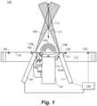
- FIG. 1 an illustrative view of an embodiment of an air data sensor in accordance with the disclosure is shown in Fig. 1 and is designated generally by reference character 100.
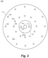
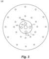
- FIGs. 2 and 3 Other embodiments and/or aspects of this disclosure are shown in Figs. 2 and 3 .
- Certain embodiments described herein can be used to provide more air data parameters than an acoustic only system, as well as more accurate, compensated parameters.
- an air data sensor 100 can include an acoustic transmitter 101 configured to output an acoustic signal 103 into an airflow and a plurality of acoustic transducers 105 configured to receive the acoustic signal 103 output by the acoustic transducer 105.
- Any suitable acoustic transducer 105 e.g., a MEMS sensor is contemplated herein.
- the air data sensor 100 can also include a light source 107 (e.g., a laser) configured to output a light beam 109 into the airflow.
- the air data sensor 100 includes a light receiver 111 configured to receive scattered light from the light beam 109 (e.g., within a field of view 113).
- the light source 107 and the light receiver 111 can be bistatic such that a measurement zone 115 is formed away from the air data sensor.
- the term "bistatic" means that a light source 105 and a receiver 111 are separated (e.g., as in a radar system comprising a transmitter and receiver that are separated by a distance comparable to the expected target distance).
- the measurement zone 115 is the area/volume of intersecting portions of the field of projection of the light source 107 and the field of view of the receiver 111, for example.
- a bistatic arrangement can reliably provide an orthogonal airspeed reading and can allow distance away from the plate that reading is taken to be chosen.
- a uniaxial system e.g., having a single telescope for source 107 and receiver 111
- a time of flight arrangement can be used to choose the measurement volume (away from the sensor body), and the measurement direction would be in the axis of the singular telescope.
- Such an embodiment may require that the telescope be placed in a location that allows it to be pointed orthogonally out of the plate body.
- a bistatic arrangement can be beneficial, however, because of the natural shape of certain acoustic horns associated with certain embodiments of the transmitter 101, and the angels of the edge of that horn which can allow a bistatic laser sensing assembly to define a measurement volume a short distance away from the plate body and/or the horn while still providing truly orthogonal airspeed information.
- the air data sensor 100 can include a plate body 117 (e.g., circular or any other shape).
- the air data sensor 100 can include one or more lenses 119a, b (e.g., at least partially transparent to the light beam 109) mounted to the plate body 117 and disposed in optical communication with each the light source 107 and the light receiver 111.
- the one or more lenses 119a, 119b can be disposed over each of the light source 107 and the light receiver 111 (e.g., over a portion of aperture 121 of the plate body 117).
- the aperture 121 can be formed centrally in the plate body 117 as shown, or in any other suitable position.
- Each lens 119a, b and/or light source 107 and/or receiver 111 can be mounted onto and/or through and/or form part of a horn 101a of the acoustic transmitter 101. Any other suitable arrangement is contemplated herein.
- the plurality of acoustic transducers 105 can be disposed on an outer surface 123 of the plate body 117.
- the acoustic transducer 105 can be disposed in any suitable pattern (e.g., circumferentially around the plate body 117 as shown or in any other suitable manner appreciated by those having ordinary skill in the art in view of this disclosure).
- the acoustic transmitter 101, the light source 107, and the light receiver 111 can be disposed at least partially within the aperture 121.
- the light source 107 and the light receiver 111 can be disposed in one or more separate apertures defined in the plate body 117, for example (e.g., individual channels capped with each respective lens 119a, 119b, respectively). Any other suitable position is contemplated herein.
- the light source 107 and the light receiver 111 can be disposed on opposite sides of the acoustic transmitter 101 and angled inward toward the acoustic transmitter 101, e.g., as shown in Fig. 1 .
- the angle can be optimized based on an acoustic horn geometry (e.g., the wave guide for the acoustic transmitter) and the geometry of the laser configuration in terms of setting the measurement zone position.
- the acoustic transmitter 101 can be aligned centered to the plate body 117, for example.
- the light source 107 and the light receiver 111 can be disposed equidistant (e.g., and angled equally) from the acoustic transmitter 101 such that the measurement zone 115 is centered (e.g., symmetrically) above the acoustic transmitter 101.
- the light source 107 and the light receiver 111 can be angled such that the measurement zone 115 is about 6 inches to about 12 inches away from the plate body 117. In certain embodiments, the light source 107 and the light receiver 111 can be angled such that the measurement zone 115 is outside of a boundary layer thickness of airflow.
- the light source 107 and the light receiver 111 can be angled between about 10 to about 20 degree. In certain embodiments, the light source 107 and the light receiver 111 can be angled relative to each respective lens 119a, 119b, for example. Any suitable angle that allows light to travel through each respective lens 119a, 119b is contemplated herein. In certain embodiments, the lens 119a and/or 119b can form part of the light source 107 and/or light receiver 111.
- an air data sensor 100 can include one or more additional light sources 107b and/or light receivers 111b.
- the one or more additional light sources 107b and receivers 111b can be bistatic. It is contemplated that the additional bistatic pair 107b, 111b can be redundant to the bistatic pair 107, 111 such that the measurement zone 115 is the same (e.g., such that light sources 107, 107b operate intermittently).
- the additional bistatic pair 107b, 111b can have a different measurement zone than measurement zone 115 (e.g., with no overlap or some overlap) of the bistatic pair 107, 111.
- the additional measurement zone can be entirely separate from the measurement zone 115 such that a different area (e.g., within the boundary layer, further away from the plate body 117 along centerline, off center, and/or any other suitable area) can be measured.
- the data from different receivers can be averaged (e.g., by air data module 125 described below).
- the one or more light sources can be a laser and the acoustic transmitter 101 can be an ultrasonic transmitter, for example. Any other suitable light source and/or acoustic transmitter are contemplated herein.
- the acoustic transmitter 101 can be any suitable size (e.g, about 2 to about 4 inches in diameter) and configured to output any suitable amplitude (e.g., sufficient to clear ice on the lens 119).
- the light receiver 111 can be or include any suitable collection optics, for example (e.g., a camera).
- the air data sensor 100 includes an air data module 125 operatively connected to the light receiver 111, the light source 107, and the acoustic transducers 105.
- the air data module 125 can be configured to receive light data from the light receiver 111 and acoustic data from the plurality of acoustic transducers 105.
- the air data module 125 can be configured to determine at least one of a local static pressure measurement, a static air temperature (SAT), and/or an orthogonal velocity component (orthogonal to the plane defined by the surface 123 of the plate body 117).
- SAT static air temperature
- the air data module 125 can be configured to provide at least one of a pressure altitude, a sideslip compensation (e.g., also referred to as beta-compensation), and/or one or more correction inputs to one or more acoustic data measurements.
- the air data module 125 can be configured to determine a forward airspeed and angle of attack (AOA) using signals from the acoustic transducers 105, and to determine an orthogonal airspeed to measure angle of sideslip (AOS) using signals from the light receiver 111. Any other suitable determination by the air data module 125 is contemplated herein.
- the air data module 125 can include any suitable hardware and/or software module(s) as appreciated by those having ordinary skill in the art.
- a method can include using an acoustic (e.g., ultrasonic) air data sensor assembly to determine one or more first air data parameters of an airflow and using a bistatic sensing arrangement (e.g., a bistatic laser sensing assembly) to determine one or more second air data parameters of an airflow.
- the one or more first air data parameters can include true airspeed (TAS), Mach number, static air temperature (SAT), and a two dimensional flow vector.
- the one or more second air data parameters can include local static pressure and a measure of airspeed orthogonal to the two dimensional flow vector.
- Use of the one or more embodiments of a sensing arrangement can include measuring at a measurement zone outside of a boundary layer of the airflow. Use of the one or more embodiments of the sensing arrangement can include measuring at a measurement zone between about 6 inches to about 12 inches away from the acoustic air data system. Any other suitable distances and/or locations are contemplated herein.
- Use of the sensing arrangement can include using a plurality of laser/receiver pairs having different measurements zones. In certain embodiments, the different measurement zones do not overlap. In certain embodiments, use of the laser sensing assembly includes using Rayleigh scattering to determine the one or more second air data parameters. Any other suitable type of measurement scheme is contemplated herein.
- embodiments can include a circular or elliptical plate with an array of microphones and an acoustic (e.g., ultrasonic) transmitter.
- the transmitter can include a horn feature that directs the acoustic energy in a radial direction towards the microphones, for example.
- Embodiments can optimize the radial space and angles for a bistatic laser system that provides an overlap measurement area in the range at a desired distance (e.g., about 6 to about 12 inches) from the face of the plate.
- Embodiments can include one or more pairs of laser transmitters/receivers depending on the level of redundancy or performance desired.
- the addition of a the laser sensing assembly can provide both a local static pressure measurement that can be used to measure pressure altitude and/or as a calibration input, a second source of static air temperature (SAT) that can be used to improve the speed of sound measurement from the acoustic system as well as further correct the air data calculations that are based on the ultrasonic time-of-flight (TOF) signals, and can provide a measurement of the orthogonal velocity component which can provide beta-compensation and additional correction inputs to the ultrasonic-based velocity measurements.
- SAT static air temperature
- Embodiments can allow for the high amplitude acoustic (e.g., ultrasonic) source to actively clean and/or deice the optical windows for the laser and collection optics which can reduce or eliminate the need for a heating system to maintain operability of the optics which reduces weight.
- Embodiments can focus the laser measurement close to the boundary layer such that increased signal-to-noise ratio can be obtained.
- Embodiments of a light/receiver system can augment the ultrasonic system to obtain all desired sensor data (e.g., 3 dimensional velocity and pressure readings that may not be obtainable using only the acoustic measurement systems).
- Embodiments can allow sideslip compensation and pressure altitude deduction from a single sensor.
- Embodiments can include multiple lasers and receivers for redundancy and/or averaging of the measurements, which can be in different positions and/or have different focal points (e.g., one at 6 inches, the other at 12).
- multiple lasers can run simultaneously, e.g., if the receiver field of view of both do not overlap with the laser field of projection of the other.
- multiple bistatic laser sensing assemblies can be configured to determine different velocity vectors, for example.
- Certain embodiments can use a molecular based scattering of the laser light to measure a volume of air directly above the ultrasonic transmitter which can provide a local, non-pneumatic static pressure for calibration purposes and pressure altitude, a second source of static air temperature to augment the ultrasonic based speed of sound measurement, and a measurement of the orthogonal velocity component for beta compensation and angle of sideslip (AOS) calculation.
- the addition of the laser in a strategic location can take advantage of the source horn design and allow for a single sensor unit to provide a fully dissimilar channel of air data parameters and improve on the performance of the ultrasonic sensing.
- Embodiments can include a single unit that can provide a complete single set of air data parameters.
- the light measurements can be used to augment the acoustic measurements in order to increase performance, for example.
- acoustic systems cannot provide a static pressure measurement and a 3rd dimension of velocity.
- Embodiments of a light system can provide these parameters. Static pressure is required for the computation of Calibrated Airspeed (CAS), which can be desired by pilots for flying by CAS (not TAS), as well as for computing pressure altitude.
- CAS Calibrated Airspeed
- the light measurement system can be used to calibrate Mach, AOA, and SAT computed based on acoustic data.
- aspects of the present disclosure may be embodied as a system, method, or computer program product. Accordingly, aspects of this disclosure may take the form of an entirely hardware embodiment, an entirely software embodiment (including firmware, resident software, micro-code, etc.), or an embodiment combining software and hardware aspects, all possibilities of which can be referred to herein as a "circuit,” “module,” or “system.”
- a “circuit,” “module,” or “system” can include one or more portions of one or more separate physical hardware and/or software components that can together perform the disclosed function of the "circuit,” “module,” or “system”, or a “circuit,” “module,” or “system” can be a single self-contained unit (e.g., of hardware and/or software).
- aspects of this disclosure may take the form of a computer program product embodied in one or more computer readable medium(s) having computer readable program code embodied thereon.
- the computer readable medium may be a computer readable signal medium or a computer readable storage medium.
- a computer readable storage medium may be, for example, but not limited to, an electronic, magnetic, optical, electromagnetic, infrared, or semiconductor system, apparatus, or device, or any suitable combination of the foregoing.
- a computer readable storage medium may be any tangible medium that can contain, or store a program for use by or in connection with an instruction execution system, apparatus, or device.
- a computer readable signal medium may include a propagated data signal with computer readable program code embodied therein, for example, in baseband or as part of a carrier wave. Such a propagated signal may take any of a variety of forms, including, but not limited to, electro-magnetic, optical, or any suitable combination thereof.
- a computer readable signal medium may be any computer readable medium that is not a computer readable storage medium and that can communicate, propagate, or transport a program for use by or in connection with an instruction execution system, apparatus, or device.
- Program code embodied on a computer readable medium may be transmitted using any appropriate medium, including but not limited to wireless, wireline, optical fiber cable, RF, etc., or any suitable combination of the foregoing.
- Computer program code for carrying out operations for aspects of this disclosure may be written in any combination of one or more programming languages, including an object oriented programming language such as Java, Smalltalk, C++ or the like and conventional procedural programming languages, such as the "C" programming language or similar programming languages.
- the program code may execute entirely on the user's computer, partly on the user's computer, as a stand-alone software package, partly on the user's computer and partly on a remote computer or entirely on the remote computer or server.
- the remote computer may be connected to the user's computer through any type of network, including a local area network (LAN) or a wide area network (WAN), or the connection may be made to an external computer (for example, through the Internet using an Internet Service Provider).
- LAN local area network
- WAN wide area network
- Internet Service Provider for example, AT&T, MCI, Sprint, EarthLink, MSN, GTE, etc.
- These computer program instructions may also be stored in a computer readable medium that can direct a computer, other programmable data processing apparatus, or other devices to function in a particular manner, such that the instructions stored in the computer readable medium produce an article of manufacture including instructions which implement the function/act specified in the flowchart and/or block diagram block or blocks.
- the computer program instructions may also be loaded onto a computer, other programmable data processing apparatus, or other devices to cause a series of operational steps to be performed on the computer, other programmable apparatus or other devices to produce a computer implemented process such that the instructions which execute on the computer or other programmable apparatus provide processes for implementing the functions/acts specified herein.
Landscapes
- Engineering & Computer Science (AREA)
- Physics & Mathematics (AREA)
- General Physics & Mathematics (AREA)
- Radar, Positioning & Navigation (AREA)
- Remote Sensing (AREA)
- Aviation & Aerospace Engineering (AREA)
- Multimedia (AREA)
- Acoustics & Sound (AREA)
- Computer Networks & Wireless Communication (AREA)
- Electromagnetism (AREA)
- Health & Medical Sciences (AREA)
- Life Sciences & Earth Sciences (AREA)
- Chemical & Material Sciences (AREA)
- Analytical Chemistry (AREA)
- Biochemistry (AREA)
- General Health & Medical Sciences (AREA)
- Immunology (AREA)
- Pathology (AREA)
- Measuring Fluid Pressure (AREA)
- Investigating Or Analyzing Materials By The Use Of Ultrasonic Waves (AREA)
- Investigating Or Analysing Materials By Optical Means (AREA)
Claims (15)
- Capteur de données d'air (100) comprenant :un émetteur acoustique (101) configuré pour émettre un signal acoustique dans un flux d'air ;une pluralité de transducteurs acoustiques (105) configurés pour recevoir le signal acoustique émis par l'émetteur acoustique ;caractérisé parune source lumineuse (107) configurée pour émettre un faisceau lumineux dans le flux d'air ; etun récepteur de lumière (111) configuré pour recevoir la lumière diffusée du faisceau lumineux, et un module de données d'air (125) connecté de manière fonctionnelle au récepteur de lumière, à la source de lumière et aux transducteurs acoustiques et configuré pour recevoir des données de lumière du récepteur de lumière pour déterminer un ou plusieurs seconds paramètres de données d'air du flux d'air et recevoir des données acoustiques de la pluralité de transducteurs acoustiques pour déterminer un ou plusieurs premiers paramètres de données d'air du flux d'air, dans lequel le module de données d'air est configuré pour déterminer au moins l'une d'une mesure de pression statique locale et d'une température d'air statique et pour augmenter les données acoustiques avec les données de lumière.
- Capteur de données d'air selon la revendication 1, dans lequel la source lumineuse et le récepteur de lumière sont bistatiques de sorte qu'une zone de mesure est formée à distance du capteur de données d'air.
- Capteur de données d'air selon la revendication 2, comprenant en outre :un corps de plaque (117) ; etune ou plusieurs lentilles (119a) montées sur le corps de plaque (117) et disposées en communication optique avec la source lumineuse (107) et le récepteur de lumière (111).
- Capteur de données d'air selon la revendication 3, dans lequel la pluralité de transducteurs acoustiques sont disposés sur une surface extérieure du corps de plaque (117), ou
dans lequel l'émetteur acoustique, la source lumineuse (107) et le récepteur de lumière (111) sont disposés au moins partiellement à l'intérieur de l'ouverture (112). - Capteur de données d'air selon la revendication 4, dans lequel la source lumineuse (107) et le récepteur de lumière (111) sont disposés sur des côtés opposés de l'émetteur acoustique (101) et inclinés vers l'intérieur en direction de l'émetteur acoustique, et facultativement dans lequel l'émetteur acoustique est aligné centré sur le corps de plaque (117), dans lequel la source lumineuse et le récepteur de lumière sont disposés à égale distance de l'émetteur acoustique de sorte que la zone de mesure est centrée au-dessus du corps de plaque.
- Capteur de données d'air selon la revendication 3, dans lequel la source lumineuse (107) et le récepteur de lumière (111) sont inclinés de telle sorte que la zone de mesure est éloignée d'environ 15,24 cm (6 pouces) à environ 30,48 cm (12 pouces) du corps de plaque (117), ou dans lequel la source lumineuse (107) et le récepteur de lumière (111) sont inclinés de telle sorte que la zone de mesure est à l'extérieur d'une épaisseur de couche limite de flux d'air.
- Capteur de données d'air selon une quelconque revendication précédente, dans lequel la source lumineuse (107) est un laser et l'émetteur acoustique est un émetteur ultrasonore.
- Capteur de données d'air selon une quelconque revendication précédente, comprenant en outre une composante de vitesse orthogonale pour fournir au moins une parmi une altitude de pression, une compensation de dérapage et/ou une ou plusieurs entrées de correction à une ou plusieurs mesures de données acoustiques.
- Capteur de données d'air selon une quelconque revendication précédente, dans lequel le module de données d'air est configuré pour déterminer une vitesse anémométrique avant et un angle d'attaque (AOA) en utilisant des signaux provenant des transducteurs acoustiques, et pour déterminer une vitesse anémométrique orthogonale pour mesurer l'angle de dérapage (AOS) en utilisant des signaux du récepteur de lumière.
- Procédé comprenant :l'utilisation d'un ensemble capteur de données d'air à ultrasons pour déterminer un ou plusieurs premiers paramètres de données d'air d'un flux d'air ; caractérisé parl'utilisation d'un agencement de détection bistatique pour déterminer un ou plusieurs seconds paramètres de données d'air d'un flux d'air ; dans lequel l'agencement de détection bistatique comprend une source lumineuse bistatique et un récepteur de lumière bistatique configuré pour utiliser des mesures de lumière pour augmenter le premier paramètre de données d'air.
- Procédé selon la revendication 10, dans lequel les un ou plusieurs premiers paramètres de données d'air comportent la vitesse vraie (TAS), le nombre de Mach, la température statique de l'air (SAT) ou un vecteur de flux bidimensionnel.
- Procédé selon la revendication 11, dans lequel les un ou plusieurs seconds paramètres de données d'air comportent la pression locale ou une mesure de vitesse orthogonale orthogonale au vecteur de flux bidimensionnel.
- Procédé selon l'une quelconque des revendications 10 à 12, dans lequel l'utilisation de l'agencement de détection bistatique comporte la mesure au niveau d'une zone de mesure à l'extérieur d'une couche limite du flux d'air.
- Procédé selon l'une quelconque des revendications 10 à 13, dans lequel l'utilisation de l'agencement de détection bistatique comporte la mesure au niveau d'une zone de mesure entre environ 15,24 cm (6 pouces) et environ 30,48 cm (12 pouces) du système de données d'air à ultrasons, ou dans lequel l'utilisation de l'agencement de détection bistatique comporte l'utilisation de la diffusion de Rayleigh pour déterminer les un ou plusieurs seconds paramètres de données d'air.
- Procédé selon l'une quelconque des revendications 10 à 14, comprenant en outre l'utilisation de l'agencement de détection bistatique comporte l'utilisation d'une pluralité de lasers bistatiques ayant différentes zones de mesure, et éventuellement
dans lequel les différentes zones de mesure ne se chevauchent pas.
Priority Applications (1)
| Application Number | Priority Date | Filing Date | Title |
|---|---|---|---|
| EP23168581.9A EP4235218A3 (fr) | 2019-07-26 | 2019-12-12 | Systèmes de données d'air |
Applications Claiming Priority (1)
| Application Number | Priority Date | Filing Date | Title |
|---|---|---|---|
| US16/523,254 US11486891B2 (en) | 2019-07-26 | 2019-07-26 | Air data systems |
Related Child Applications (1)
| Application Number | Title | Priority Date | Filing Date |
|---|---|---|---|
| EP23168581.9A Division EP4235218A3 (fr) | 2019-07-26 | 2019-12-12 | Systèmes de données d'air |
Publications (2)
| Publication Number | Publication Date |
|---|---|
| EP3770609A1 EP3770609A1 (fr) | 2021-01-27 |
| EP3770609B1 true EP3770609B1 (fr) | 2023-05-03 |
Family
ID=68887274
Family Applications (2)
| Application Number | Title | Priority Date | Filing Date |
|---|---|---|---|
| EP19215549.7A Active EP3770609B1 (fr) | 2019-07-26 | 2019-12-12 | Systèmes de données d'air |
| EP23168581.9A Pending EP4235218A3 (fr) | 2019-07-26 | 2019-12-12 | Systèmes de données d'air |
Family Applications After (1)
| Application Number | Title | Priority Date | Filing Date |
|---|---|---|---|
| EP23168581.9A Pending EP4235218A3 (fr) | 2019-07-26 | 2019-12-12 | Systèmes de données d'air |
Country Status (3)
| Country | Link |
|---|---|
| US (1) | US11486891B2 (fr) |
| EP (2) | EP3770609B1 (fr) |
| CA (1) | CA3064935A1 (fr) |
Cited By (1)
| Publication number | Priority date | Publication date | Assignee | Title |
|---|---|---|---|---|
| US20220244286A1 (en) * | 2019-06-05 | 2022-08-04 | Bae Systems Plc | Aircraft with air data sensor |
Families Citing this family (4)
| Publication number | Priority date | Publication date | Assignee | Title |
|---|---|---|---|---|
| US11467177B2 (en) | 2020-03-20 | 2022-10-11 | Rosemount Aerospace Inc. | Acoustic air data system with radially paired receivers |
| US12486041B2 (en) * | 2021-05-04 | 2025-12-02 | The Boeing Company | Computation of aircraft airspeed by inclusion of static air temperature |
| CA3185496A1 (fr) * | 2021-12-20 | 2023-06-20 | Rosemount Aerospace Inc. | Generateur d'ondes pour des systemes de donnees aerodynamiques ultrasoniques |
| US12372033B1 (en) * | 2024-03-05 | 2025-07-29 | General Electric Company | Turbine engine with sound-based active control |
Family Cites Families (15)
| Publication number | Priority date | Publication date | Assignee | Title |
|---|---|---|---|---|
| JP2913580B2 (ja) | 1996-03-18 | 1999-06-28 | 株式会社コミュータヘリコプタ先進技術研究所 | スキッド式航空機の接地検出装置 |
| WO2004012994A2 (fr) * | 2002-08-02 | 2004-02-12 | Ophir Corporation | Systemes et procedes optiques de mesure de parametres de l'air |
| US7155969B2 (en) * | 2003-12-10 | 2007-01-02 | Rosemount Aerospace Inc. | System for and method of acoustic and through skin air data measurement |
| US20100152933A1 (en) | 2008-12-11 | 2010-06-17 | Honeywell International Inc. | Apparatus and method for unmanned aerial vehicle ground proximity detection, landing and descent |
| WO2012105973A1 (fr) * | 2011-02-02 | 2012-08-09 | Michigan Aerospace Corporation | Système et procédé de mesure atmosphérique |
| JP5376459B2 (ja) | 2010-03-09 | 2013-12-25 | 独立行政法人 宇宙航空研究開発機構 | 光学式エアデータセンサ |
| US9086488B2 (en) * | 2010-04-20 | 2015-07-21 | Michigan Aerospace Corporation | Atmospheric measurement system and method |
| DE102010019811A1 (de) | 2010-05-06 | 2011-11-10 | Airbus Operations Gmbh | Verfahren und Vorrichtung zur Messung der Strömungsgeschwindigkeit mittels eines Plasmas |
| US8915709B2 (en) | 2010-12-30 | 2014-12-23 | Vestas Wind Systems A/S | Optical angle of attack detector based on light detection and ranging (LIDAR) for control of an aerodynamic surface |
| US20120173191A1 (en) * | 2011-01-03 | 2012-07-05 | Moeller Lothar B | Airspeed And Velocity Of Air Measurement |
| US8908160B2 (en) * | 2011-12-23 | 2014-12-09 | Optical Air Data Systems, Llc | Optical air data system suite of sensors |
| US10101443B1 (en) | 2016-12-02 | 2018-10-16 | Amazon Technologies, Inc. | Airframe-embedded ultrasonic transducers |
| TWI620687B (zh) | 2017-01-24 | 2018-04-11 | 林清富 | 用於無人飛行器之操控系統及其使用之中介裝置與無人飛行器 |
| US10908277B1 (en) * | 2017-07-12 | 2021-02-02 | Rockwell Collins, Inc. | Maintaining position relative to an air anomaly |
| US11169173B2 (en) * | 2019-05-15 | 2021-11-09 | Rosemount Aerospace Inc. | Air data system architectures including laser air data and acoustic air data sensors |
-
2019
- 2019-07-26 US US16/523,254 patent/US11486891B2/en active Active
- 2019-12-11 CA CA3064935A patent/CA3064935A1/fr active Pending
- 2019-12-12 EP EP19215549.7A patent/EP3770609B1/fr active Active
- 2019-12-12 EP EP23168581.9A patent/EP4235218A3/fr active Pending
Cited By (2)
| Publication number | Priority date | Publication date | Assignee | Title |
|---|---|---|---|---|
| US20220244286A1 (en) * | 2019-06-05 | 2022-08-04 | Bae Systems Plc | Aircraft with air data sensor |
| US11774466B2 (en) * | 2019-06-05 | 2023-10-03 | Bae Systems Plc | Aircraft with skin layer air data sensor |
Also Published As
| Publication number | Publication date |
|---|---|
| US11486891B2 (en) | 2022-11-01 |
| CA3064935A1 (fr) | 2021-01-26 |
| EP3770609A1 (fr) | 2021-01-27 |
| BR102019026676A2 (pt) | 2021-02-09 |
| EP4235218A3 (fr) | 2024-01-03 |
| US20210025916A1 (en) | 2021-01-28 |
| EP4235218A2 (fr) | 2023-08-30 |
Similar Documents
| Publication | Publication Date | Title |
|---|---|---|
| EP3770609B1 (fr) | Systèmes de données d'air | |
| US8451435B2 (en) | Optical anemometric probe with two measurement axes | |
| US10191144B2 (en) | Radar mounting estimation with unstructured data | |
| US9612252B2 (en) | Ultrasonic airspeed and direction sensor system | |
| EP3739343B1 (fr) | Architectures de système de données d'air comprenant des capteurs de données d'air laser et de données d'air acoustique | |
| CN110730913B (zh) | 退化可视环境的分布式多节点低频雷达系统的方法和设备 | |
| CN107121666A (zh) | 一种基于无人飞行器的临近空间运动目标定位方法 | |
| WO2018168564A1 (fr) | Drone pour mesurer la profondeur d'eau d'un champ | |
| JPS63503166A (ja) | 受動電波高度計 | |
| EP3693746A1 (fr) | Système de données d'air acoustique | |
| JP2021063741A (ja) | 飛行体用対気速度及び風向計測装置及びその計測方法 | |
| US9612310B2 (en) | Method and apparatus for determining the direction of arrival of a sonic boom | |
| AU2019256003B2 (en) | A device for determining orientation of an object | |
| Martin et al. | Passive acoustic method for aircraft states estimation based on the Doppler effect | |
| US9562961B1 (en) | Apparatus, method, and system for estimating the angle of arrival of a signal | |
| CA3172055A1 (fr) | Capteur optique multifibre pour aeronef leger | |
| JP2014134405A (ja) | 計測システム、及び計測方法 | |
| US11714098B2 (en) | Acoustic air data systems | |
| EP3318896A1 (fr) | Systèmes et procédés pour utiliser des technologies lidar dissemblables | |
| US20230175922A1 (en) | Systems for Mechanical Static and Dynamic Characterization of Structures and Adjustment of Radio Frequency Aperture and Transmission | |
| JPH05142341A (ja) | 受動型ssr装置 | |
| BR102019026676B1 (pt) | Sensor de dados aéreos, e, método | |
| Jiao et al. | Azimuth-only Passive Location of UAV Formation Based on Differential Evolution Algorithm | |
| RU2626243C1 (ru) | Способ определения пространственных координат объектов и система для его реализации | |
| JP2022065535A (ja) | 飛行体用対気速度及び風向計測装置、計測方法並びに計測プログラム |
Legal Events
| Date | Code | Title | Description |
|---|---|---|---|
| PUAI | Public reference made under article 153(3) epc to a published international application that has entered the european phase |
Free format text: ORIGINAL CODE: 0009012 |
|
| STAA | Information on the status of an ep patent application or granted ep patent |
Free format text: STATUS: THE APPLICATION HAS BEEN PUBLISHED |
|
| AK | Designated contracting states |
Kind code of ref document: A1 Designated state(s): AL AT BE BG CH CY CZ DE DK EE ES FI FR GB GR HR HU IE IS IT LI LT LU LV MC MK MT NL NO PL PT RO RS SE SI SK SM TR |
|
| AX | Request for extension of the european patent |
Extension state: BA ME |
|
| STAA | Information on the status of an ep patent application or granted ep patent |
Free format text: STATUS: REQUEST FOR EXAMINATION WAS MADE |
|
| 17P | Request for examination filed |
Effective date: 20210727 |
|
| RBV | Designated contracting states (corrected) |
Designated state(s): AL AT BE BG CH CY CZ DE DK EE ES FI FR GB GR HR HU IE IS IT LI LT LU LV MC MK MT NL NO PL PT RO RS SE SI SK SM TR |
|
| GRAP | Despatch of communication of intention to grant a patent |
Free format text: ORIGINAL CODE: EPIDOSNIGR1 |
|
| STAA | Information on the status of an ep patent application or granted ep patent |
Free format text: STATUS: GRANT OF PATENT IS INTENDED |
|
| RIC1 | Information provided on ipc code assigned before grant |
Ipc: G01S 15/00 20200101ALN20221122BHEP Ipc: B64D 43/02 20060101ALN20221122BHEP Ipc: G01S 17/00 20200101ALI20221122BHEP Ipc: G01S 15/60 20060101ALI20221122BHEP Ipc: G01S 7/521 20060101ALI20221122BHEP Ipc: G01S 17/58 20060101ALI20221122BHEP Ipc: G01S 15/86 20200101ALI20221122BHEP Ipc: G01P 5/26 20060101ALI20221122BHEP Ipc: G01P 13/02 20060101ALI20221122BHEP Ipc: G01P 5/24 20060101AFI20221122BHEP |
|
| RIC1 | Information provided on ipc code assigned before grant |
Ipc: G01S 15/00 20200101ALN20221206BHEP Ipc: B64D 43/02 20060101ALN20221206BHEP Ipc: G01S 17/00 20200101ALI20221206BHEP Ipc: G01S 15/60 20060101ALI20221206BHEP Ipc: G01S 7/521 20060101ALI20221206BHEP Ipc: G01S 17/58 20060101ALI20221206BHEP Ipc: G01S 15/86 20200101ALI20221206BHEP Ipc: G01P 5/26 20060101ALI20221206BHEP Ipc: G01P 13/02 20060101ALI20221206BHEP Ipc: G01P 5/24 20060101AFI20221206BHEP |
|
| INTG | Intention to grant announced |
Effective date: 20221220 |
|
| GRAS | Grant fee paid |
Free format text: ORIGINAL CODE: EPIDOSNIGR3 |
|
| GRAA | (expected) grant |
Free format text: ORIGINAL CODE: 0009210 |
|
| STAA | Information on the status of an ep patent application or granted ep patent |
Free format text: STATUS: THE PATENT HAS BEEN GRANTED |
|
| AK | Designated contracting states |
Kind code of ref document: B1 Designated state(s): AL AT BE BG CH CY CZ DE DK EE ES FI FR GB GR HR HU IE IS IT LI LT LU LV MC MK MT NL NO PL PT RO RS SE SI SK SM TR |
|
| REG | Reference to a national code |
Ref country code: GB Ref legal event code: FG4D |
|
| REG | Reference to a national code |
Ref country code: DE Ref legal event code: R096 Ref document number: 602019028324 Country of ref document: DE |
|
| REG | Reference to a national code |
Ref country code: AT Ref legal event code: REF Ref document number: 1565046 Country of ref document: AT Kind code of ref document: T Effective date: 20230515 Ref country code: CH Ref legal event code: EP |
|
| REG | Reference to a national code |
Ref country code: IE Ref legal event code: FG4D |
|
| REG | Reference to a national code |
Ref country code: LT Ref legal event code: MG9D |
|
| REG | Reference to a national code |
Ref country code: NL Ref legal event code: MP Effective date: 20230503 |
|
| REG | Reference to a national code |
Ref country code: AT Ref legal event code: MK05 Ref document number: 1565046 Country of ref document: AT Kind code of ref document: T Effective date: 20230503 |
|
| PG25 | Lapsed in a contracting state [announced via postgrant information from national office to epo] |
Ref country code: SE Free format text: LAPSE BECAUSE OF FAILURE TO SUBMIT A TRANSLATION OF THE DESCRIPTION OR TO PAY THE FEE WITHIN THE PRESCRIBED TIME-LIMIT Effective date: 20230503 Ref country code: PT Free format text: LAPSE BECAUSE OF FAILURE TO SUBMIT A TRANSLATION OF THE DESCRIPTION OR TO PAY THE FEE WITHIN THE PRESCRIBED TIME-LIMIT Effective date: 20230904 Ref country code: NO Free format text: LAPSE BECAUSE OF FAILURE TO SUBMIT A TRANSLATION OF THE DESCRIPTION OR TO PAY THE FEE WITHIN THE PRESCRIBED TIME-LIMIT Effective date: 20230803 Ref country code: NL Free format text: LAPSE BECAUSE OF FAILURE TO SUBMIT A TRANSLATION OF THE DESCRIPTION OR TO PAY THE FEE WITHIN THE PRESCRIBED TIME-LIMIT Effective date: 20230503 Ref country code: ES Free format text: LAPSE BECAUSE OF FAILURE TO SUBMIT A TRANSLATION OF THE DESCRIPTION OR TO PAY THE FEE WITHIN THE PRESCRIBED TIME-LIMIT Effective date: 20230503 Ref country code: AT Free format text: LAPSE BECAUSE OF FAILURE TO SUBMIT A TRANSLATION OF THE DESCRIPTION OR TO PAY THE FEE WITHIN THE PRESCRIBED TIME-LIMIT Effective date: 20230503 |
|
| PG25 | Lapsed in a contracting state [announced via postgrant information from national office to epo] |
Ref country code: RS Free format text: LAPSE BECAUSE OF FAILURE TO SUBMIT A TRANSLATION OF THE DESCRIPTION OR TO PAY THE FEE WITHIN THE PRESCRIBED TIME-LIMIT Effective date: 20230503 Ref country code: PL Free format text: LAPSE BECAUSE OF FAILURE TO SUBMIT A TRANSLATION OF THE DESCRIPTION OR TO PAY THE FEE WITHIN THE PRESCRIBED TIME-LIMIT Effective date: 20230503 Ref country code: LV Free format text: LAPSE BECAUSE OF FAILURE TO SUBMIT A TRANSLATION OF THE DESCRIPTION OR TO PAY THE FEE WITHIN THE PRESCRIBED TIME-LIMIT Effective date: 20230503 Ref country code: LT Free format text: LAPSE BECAUSE OF FAILURE TO SUBMIT A TRANSLATION OF THE DESCRIPTION OR TO PAY THE FEE WITHIN THE PRESCRIBED TIME-LIMIT Effective date: 20230503 Ref country code: IS Free format text: LAPSE BECAUSE OF FAILURE TO SUBMIT A TRANSLATION OF THE DESCRIPTION OR TO PAY THE FEE WITHIN THE PRESCRIBED TIME-LIMIT Effective date: 20230903 Ref country code: HR Free format text: LAPSE BECAUSE OF FAILURE TO SUBMIT A TRANSLATION OF THE DESCRIPTION OR TO PAY THE FEE WITHIN THE PRESCRIBED TIME-LIMIT Effective date: 20230503 Ref country code: GR Free format text: LAPSE BECAUSE OF FAILURE TO SUBMIT A TRANSLATION OF THE DESCRIPTION OR TO PAY THE FEE WITHIN THE PRESCRIBED TIME-LIMIT Effective date: 20230804 |
|
| PG25 | Lapsed in a contracting state [announced via postgrant information from national office to epo] |
Ref country code: FI Free format text: LAPSE BECAUSE OF FAILURE TO SUBMIT A TRANSLATION OF THE DESCRIPTION OR TO PAY THE FEE WITHIN THE PRESCRIBED TIME-LIMIT Effective date: 20230503 |
|
| PG25 | Lapsed in a contracting state [announced via postgrant information from national office to epo] |
Ref country code: SK Free format text: LAPSE BECAUSE OF FAILURE TO SUBMIT A TRANSLATION OF THE DESCRIPTION OR TO PAY THE FEE WITHIN THE PRESCRIBED TIME-LIMIT Effective date: 20230503 |
|
| PG25 | Lapsed in a contracting state [announced via postgrant information from national office to epo] |
Ref country code: SM Free format text: LAPSE BECAUSE OF FAILURE TO SUBMIT A TRANSLATION OF THE DESCRIPTION OR TO PAY THE FEE WITHIN THE PRESCRIBED TIME-LIMIT Effective date: 20230503 Ref country code: SK Free format text: LAPSE BECAUSE OF FAILURE TO SUBMIT A TRANSLATION OF THE DESCRIPTION OR TO PAY THE FEE WITHIN THE PRESCRIBED TIME-LIMIT Effective date: 20230503 Ref country code: RO Free format text: LAPSE BECAUSE OF FAILURE TO SUBMIT A TRANSLATION OF THE DESCRIPTION OR TO PAY THE FEE WITHIN THE PRESCRIBED TIME-LIMIT Effective date: 20230503 Ref country code: EE Free format text: LAPSE BECAUSE OF FAILURE TO SUBMIT A TRANSLATION OF THE DESCRIPTION OR TO PAY THE FEE WITHIN THE PRESCRIBED TIME-LIMIT Effective date: 20230503 Ref country code: DK Free format text: LAPSE BECAUSE OF FAILURE TO SUBMIT A TRANSLATION OF THE DESCRIPTION OR TO PAY THE FEE WITHIN THE PRESCRIBED TIME-LIMIT Effective date: 20230503 Ref country code: CZ Free format text: LAPSE BECAUSE OF FAILURE TO SUBMIT A TRANSLATION OF THE DESCRIPTION OR TO PAY THE FEE WITHIN THE PRESCRIBED TIME-LIMIT Effective date: 20230503 |
|
| REG | Reference to a national code |
Ref country code: DE Ref legal event code: R097 Ref document number: 602019028324 Country of ref document: DE |
|
| PLBE | No opposition filed within time limit |
Free format text: ORIGINAL CODE: 0009261 |
|
| STAA | Information on the status of an ep patent application or granted ep patent |
Free format text: STATUS: NO OPPOSITION FILED WITHIN TIME LIMIT |
|
| 26N | No opposition filed |
Effective date: 20240206 |
|
| PG25 | Lapsed in a contracting state [announced via postgrant information from national office to epo] |
Ref country code: SI Free format text: LAPSE BECAUSE OF FAILURE TO SUBMIT A TRANSLATION OF THE DESCRIPTION OR TO PAY THE FEE WITHIN THE PRESCRIBED TIME-LIMIT Effective date: 20230503 |
|
| PG25 | Lapsed in a contracting state [announced via postgrant information from national office to epo] |
Ref country code: SI Free format text: LAPSE BECAUSE OF FAILURE TO SUBMIT A TRANSLATION OF THE DESCRIPTION OR TO PAY THE FEE WITHIN THE PRESCRIBED TIME-LIMIT Effective date: 20230503 Ref country code: IT Free format text: LAPSE BECAUSE OF FAILURE TO SUBMIT A TRANSLATION OF THE DESCRIPTION OR TO PAY THE FEE WITHIN THE PRESCRIBED TIME-LIMIT Effective date: 20230503 |
|
| REG | Reference to a national code |
Ref country code: CH Ref legal event code: PL |
|
| PG25 | Lapsed in a contracting state [announced via postgrant information from national office to epo] |
Ref country code: LU Free format text: LAPSE BECAUSE OF NON-PAYMENT OF DUE FEES Effective date: 20231212 |
|
| PG25 | Lapsed in a contracting state [announced via postgrant information from national office to epo] |
Ref country code: MC Free format text: LAPSE BECAUSE OF FAILURE TO SUBMIT A TRANSLATION OF THE DESCRIPTION OR TO PAY THE FEE WITHIN THE PRESCRIBED TIME-LIMIT Effective date: 20230503 |
|
| REG | Reference to a national code |
Ref country code: BE Ref legal event code: MM Effective date: 20231231 |
|
| PG25 | Lapsed in a contracting state [announced via postgrant information from national office to epo] |
Ref country code: MC Free format text: LAPSE BECAUSE OF FAILURE TO SUBMIT A TRANSLATION OF THE DESCRIPTION OR TO PAY THE FEE WITHIN THE PRESCRIBED TIME-LIMIT Effective date: 20230503 Ref country code: LU Free format text: LAPSE BECAUSE OF NON-PAYMENT OF DUE FEES Effective date: 20231212 |
|
| REG | Reference to a national code |
Ref country code: IE Ref legal event code: MM4A |
|
| PG25 | Lapsed in a contracting state [announced via postgrant information from national office to epo] |
Ref country code: IE Free format text: LAPSE BECAUSE OF NON-PAYMENT OF DUE FEES Effective date: 20231212 |
|
| PG25 | Lapsed in a contracting state [announced via postgrant information from national office to epo] |
Ref country code: BE Free format text: LAPSE BECAUSE OF NON-PAYMENT OF DUE FEES Effective date: 20231231 |
|
| PG25 | Lapsed in a contracting state [announced via postgrant information from national office to epo] |
Ref country code: CH Free format text: LAPSE BECAUSE OF NON-PAYMENT OF DUE FEES Effective date: 20231231 |
|
| PG25 | Lapsed in a contracting state [announced via postgrant information from national office to epo] |
Ref country code: IE Free format text: LAPSE BECAUSE OF NON-PAYMENT OF DUE FEES Effective date: 20231212 Ref country code: CH Free format text: LAPSE BECAUSE OF NON-PAYMENT OF DUE FEES Effective date: 20231231 Ref country code: BE Free format text: LAPSE BECAUSE OF NON-PAYMENT OF DUE FEES Effective date: 20231231 |
|
| PG25 | Lapsed in a contracting state [announced via postgrant information from national office to epo] |
Ref country code: BG Free format text: LAPSE BECAUSE OF FAILURE TO SUBMIT A TRANSLATION OF THE DESCRIPTION OR TO PAY THE FEE WITHIN THE PRESCRIBED TIME-LIMIT Effective date: 20230503 |
|
| PG25 | Lapsed in a contracting state [announced via postgrant information from national office to epo] |
Ref country code: BG Free format text: LAPSE BECAUSE OF FAILURE TO SUBMIT A TRANSLATION OF THE DESCRIPTION OR TO PAY THE FEE WITHIN THE PRESCRIBED TIME-LIMIT Effective date: 20230503 |
|
| PG25 | Lapsed in a contracting state [announced via postgrant information from national office to epo] |
Ref country code: CY Free format text: LAPSE BECAUSE OF FAILURE TO SUBMIT A TRANSLATION OF THE DESCRIPTION OR TO PAY THE FEE WITHIN THE PRESCRIBED TIME-LIMIT; INVALID AB INITIO Effective date: 20191212 |
|
| PG25 | Lapsed in a contracting state [announced via postgrant information from national office to epo] |
Ref country code: HU Free format text: LAPSE BECAUSE OF FAILURE TO SUBMIT A TRANSLATION OF THE DESCRIPTION OR TO PAY THE FEE WITHIN THE PRESCRIBED TIME-LIMIT; INVALID AB INITIO Effective date: 20191212 |
|
| PG25 | Lapsed in a contracting state [announced via postgrant information from national office to epo] |
Ref country code: TR Free format text: LAPSE BECAUSE OF FAILURE TO SUBMIT A TRANSLATION OF THE DESCRIPTION OR TO PAY THE FEE WITHIN THE PRESCRIBED TIME-LIMIT Effective date: 20230503 |
|
| PGFP | Annual fee paid to national office [announced via postgrant information from national office to epo] |
Ref country code: DE Payment date: 20251126 Year of fee payment: 7 |
|
| PGFP | Annual fee paid to national office [announced via postgrant information from national office to epo] |
Ref country code: GB Payment date: 20251120 Year of fee payment: 7 |
|
| PGFP | Annual fee paid to national office [announced via postgrant information from national office to epo] |
Ref country code: FR Payment date: 20251119 Year of fee payment: 7 |
|
| P01 | Opt-out of the competence of the unified patent court (upc) registered |
Free format text: CASE NUMBER: UPC_APP_0018837_3770609/2025 Effective date: 20251222 |