EP3770629A1 - Verrouillage par injection à phase réglable - Google Patents
Verrouillage par injection à phase réglable Download PDFInfo
- Publication number
- EP3770629A1 EP3770629A1 EP20185767.9A EP20185767A EP3770629A1 EP 3770629 A1 EP3770629 A1 EP 3770629A1 EP 20185767 A EP20185767 A EP 20185767A EP 3770629 A1 EP3770629 A1 EP 3770629A1
- Authority
- EP
- European Patent Office
- Prior art keywords
- injection
- signal
- phase
- locking
- circuit
- Prior art date
- Legal status (The legal status is an assumption and is not a legal conclusion. Google has not performed a legal analysis and makes no representation as to the accuracy of the status listed.)
- Pending
Links
Images


Classifications
-
- G—PHYSICS
- G01—MEASURING; TESTING
- G01S—RADIO DIRECTION-FINDING; RADIO NAVIGATION; DETERMINING DISTANCE OR VELOCITY BY USE OF RADIO WAVES; LOCATING OR PRESENCE-DETECTING BY USE OF THE REFLECTION OR RERADIATION OF RADIO WAVES; ANALOGOUS ARRANGEMENTS USING OTHER WAVES
- G01S13/00—Systems using the reflection or reradiation of radio waves, e.g. radar systems; Analogous systems using reflection or reradiation of waves whose nature or wavelength is irrelevant or unspecified
- G01S13/02—Systems using reflection of radio waves, e.g. primary radar systems; Analogous systems
- G01S13/06—Systems determining position data of a target
- G01S13/08—Systems for measuring distance only
- G01S13/32—Systems for measuring distance only using transmission of continuous waves, whether amplitude-, frequency-, or phase-modulated, or unmodulated
- G01S13/36—Systems for measuring distance only using transmission of continuous waves, whether amplitude-, frequency-, or phase-modulated, or unmodulated with phase comparison between the received signal and the contemporaneously transmitted signal
- G01S13/40—Systems for measuring distance only using transmission of continuous waves, whether amplitude-, frequency-, or phase-modulated, or unmodulated with phase comparison between the received signal and the contemporaneously transmitted signal wherein the frequency of transmitted signal is adjusted to give a predetermined phase relationship
-
- H—ELECTRICITY
- H03—ELECTRONIC CIRCUITRY
- H03L—AUTOMATIC CONTROL, STARTING, SYNCHRONISATION OR STABILISATION OF GENERATORS OF ELECTRONIC OSCILLATIONS OR PULSES
- H03L7/00—Automatic control of frequency or phase; Synchronisation
- H03L7/06—Automatic control of frequency or phase; Synchronisation using a reference signal applied to a frequency- or phase-locked loop
- H03L7/16—Indirect frequency synthesis, i.e. generating a desired one of a number of predetermined frequencies using a frequency- or phase-locked loop
- H03L7/18—Indirect frequency synthesis, i.e. generating a desired one of a number of predetermined frequencies using a frequency- or phase-locked loop using a frequency divider or counter in the loop
-
- G—PHYSICS
- G01—MEASURING; TESTING
- G01S—RADIO DIRECTION-FINDING; RADIO NAVIGATION; DETERMINING DISTANCE OR VELOCITY BY USE OF RADIO WAVES; LOCATING OR PRESENCE-DETECTING BY USE OF THE REFLECTION OR RERADIATION OF RADIO WAVES; ANALOGOUS ARRANGEMENTS USING OTHER WAVES
- G01S13/00—Systems using the reflection or reradiation of radio waves, e.g. radar systems; Analogous systems using reflection or reradiation of waves whose nature or wavelength is irrelevant or unspecified
- G01S13/02—Systems using reflection of radio waves, e.g. primary radar systems; Analogous systems
- G01S13/06—Systems determining position data of a target
- G01S13/08—Systems for measuring distance only
- G01S13/32—Systems for measuring distance only using transmission of continuous waves, whether amplitude-, frequency-, or phase-modulated, or unmodulated
- G01S13/34—Systems for measuring distance only using transmission of continuous waves, whether amplitude-, frequency-, or phase-modulated, or unmodulated using transmission of continuous, frequency-modulated waves while heterodyning the received signal, or a signal derived therefrom, with a locally-generated signal related to the contemporaneously transmitted signal
- G01S13/343—Systems for measuring distance only using transmission of continuous waves, whether amplitude-, frequency-, or phase-modulated, or unmodulated using transmission of continuous, frequency-modulated waves while heterodyning the received signal, or a signal derived therefrom, with a locally-generated signal related to the contemporaneously transmitted signal using sawtooth modulation
-
- G—PHYSICS
- G01—MEASURING; TESTING
- G01S—RADIO DIRECTION-FINDING; RADIO NAVIGATION; DETERMINING DISTANCE OR VELOCITY BY USE OF RADIO WAVES; LOCATING OR PRESENCE-DETECTING BY USE OF THE REFLECTION OR RERADIATION OF RADIO WAVES; ANALOGOUS ARRANGEMENTS USING OTHER WAVES
- G01S7/00—Details of systems according to groups G01S13/00, G01S15/00, G01S17/00
- G01S7/02—Details of systems according to groups G01S13/00, G01S15/00, G01S17/00 of systems according to group G01S13/00
- G01S7/35—Details of non-pulse systems
-
- H—ELECTRICITY
- H01—ELECTRIC ELEMENTS
- H01Q—ANTENNAS, i.e. RADIO AERIALS
- H01Q3/00—Arrangements for changing or varying the orientation or the shape of the directional pattern of the waves radiated from an antenna or antenna system
- H01Q3/26—Arrangements for changing or varying the orientation or the shape of the directional pattern of the waves radiated from an antenna or antenna system varying the relative phase or relative amplitude of energisation between two or more active radiating elements; varying the distribution of energy across a radiating aperture
- H01Q3/30—Arrangements for changing or varying the orientation or the shape of the directional pattern of the waves radiated from an antenna or antenna system varying the relative phase or relative amplitude of energisation between two or more active radiating elements; varying the distribution of energy across a radiating aperture varying the relative phase between the radiating elements of an array
- H01Q3/34—Arrangements for changing or varying the orientation or the shape of the directional pattern of the waves radiated from an antenna or antenna system varying the relative phase or relative amplitude of energisation between two or more active radiating elements; varying the distribution of energy across a radiating aperture varying the relative phase between the radiating elements of an array by electrical means
- H01Q3/36—Arrangements for changing or varying the orientation or the shape of the directional pattern of the waves radiated from an antenna or antenna system varying the relative phase or relative amplitude of energisation between two or more active radiating elements; varying the distribution of energy across a radiating aperture varying the relative phase between the radiating elements of an array by electrical means with variable phase-shifters
- H01Q3/38—Arrangements for changing or varying the orientation or the shape of the directional pattern of the waves radiated from an antenna or antenna system varying the relative phase or relative amplitude of energisation between two or more active radiating elements; varying the distribution of energy across a radiating aperture varying the relative phase between the radiating elements of an array by electrical means with variable phase-shifters the phase-shifters being digital
-
- H—ELECTRICITY
- H04—ELECTRIC COMMUNICATION TECHNIQUE
- H04B—TRANSMISSION
- H04B1/00—Details of transmission systems, not covered by a single one of groups H04B3/00 - H04B13/00; Details of transmission systems not characterised by the medium used for transmission
- H04B1/69—Spread spectrum techniques
-
- H—ELECTRICITY
- H01—ELECTRIC ELEMENTS
- H01Q—ANTENNAS, i.e. RADIO AERIALS
- H01Q3/00—Arrangements for changing or varying the orientation or the shape of the directional pattern of the waves radiated from an antenna or antenna system
- H01Q3/26—Arrangements for changing or varying the orientation or the shape of the directional pattern of the waves radiated from an antenna or antenna system varying the relative phase or relative amplitude of energisation between two or more active radiating elements; varying the distribution of energy across a radiating aperture
- H01Q3/30—Arrangements for changing or varying the orientation or the shape of the directional pattern of the waves radiated from an antenna or antenna system varying the relative phase or relative amplitude of energisation between two or more active radiating elements; varying the distribution of energy across a radiating aperture varying the relative phase between the radiating elements of an array
- H01Q3/34—Arrangements for changing or varying the orientation or the shape of the directional pattern of the waves radiated from an antenna or antenna system varying the relative phase or relative amplitude of energisation between two or more active radiating elements; varying the distribution of energy across a radiating aperture varying the relative phase between the radiating elements of an array by electrical means
- H01Q3/42—Arrangements for changing or varying the orientation or the shape of the directional pattern of the waves radiated from an antenna or antenna system varying the relative phase or relative amplitude of energisation between two or more active radiating elements; varying the distribution of energy across a radiating aperture varying the relative phase between the radiating elements of an array by electrical means using frequency-mixing
-
- H—ELECTRICITY
- H03—ELECTRONIC CIRCUITRY
- H03D—DEMODULATION OR TRANSFERENCE OF MODULATION FROM ONE CARRIER TO ANOTHER
- H03D7/00—Transference of modulation from one carrier to another, e.g. frequency-changing
-
- H—ELECTRICITY
- H04—ELECTRIC COMMUNICATION TECHNIQUE
- H04B—TRANSMISSION
- H04B1/00—Details of transmission systems, not covered by a single one of groups H04B3/00 - H04B13/00; Details of transmission systems not characterised by the medium used for transmission
- H04B1/69—Spread spectrum techniques
- H04B2001/6912—Spread spectrum techniques using chirp
Definitions
- aspects of various embodiments are directed to injection locking, which may be facilitated by phase tuning of injection signals.
- injection locking amplifiers can be used to lock injection signals for generating a variety of outputs, such as signals used in radar transceivers. Such approaches may, for example, be useful in the automotive industry where radar-based signals can be used for a variety of applications.
- Such a system may utilize several (differential) amplifying stages tuned at an operating frequency.
- injection locking can be complex to implement, and utilize significant power in effecting locking functions. Further, lock range may be limited, amplitude may be undesirable large, and phase may vary over a signal.
- Various example embodiments are directed to issues such as those addressed above and/or others which may become apparent from the following disclosure concerning injection locking, and doing so using a phase-adjustment approach.
- aspects of the present disclosure involve the use of a feedback and/or feed forward loop to adjust the phase of an output signal generated using an injection signal.
- a feedback and/or feed forward loop may, for example, be carried out by using a feedback circuit to ascertain differences in phase between the injection signal and an amplified version of the output signal, and adjusting the phase of the output signal based on any such ascertained differences.
- an apparatus in a more specific example embodiment, includes a plurality of injection-locking circuits configured to receive an injection signal, each injection-locking circuit including a mixer and a lock-detection circuit.
- the lock-detection circuit detects a lock-status relationship between the injection signal and an output signal from the injection-locking circuit. In response to the lock-status relationship indicating an unlocked condition, a phase of the output signal is adjusted. In response to the lock-status relationship indicating a locked condition, transmission of an FM continuous wave (FMCW) chirp signal is facilitated.
- FMCW FM continuous wave
- the apparatus may further include a phase-locked loop circuit to generate the injection signal to drive each of the plurality of injection-locking circuits, each of the injection-locking circuits having an amplifier configured to provide the output signal, using the injection signal, having a phase set via the injection locking circuit.
- the mixer in each of the plurality of injection-locking circuits, may be configured to combine the injection signal and a representation of the output signal and to provide an output indicative of a phase difference between the injection signal and the output signal.
- the apparatus may further include, for each of the plurality of injection-locking circuits, an injection circuit configured to generate the injection signal and a feed forward circuit configured to set an operating voltage of the injection-locking circuit based on the injection signal.
- each of the injection-locking circuits may be configured to set the phase of the output signal in response to a tuning voltage and the injection signal, and the feed forward circuit may be configured and arranged to respond to an output of the injection circuit by setting a voltage range of the tuning voltage.
- the injection-locking circuits may be configured to adjust the phase of the output signal generated from the injection signal in response to a tuning voltage
- the lock-detection circuit may be configured to adjust the phase of the output signal by setting a voltage range of the tuning voltage
- the lock-detection circuit may include capacitor circuitry configured to cause the tuning voltage to exhibit a voltage in the tuning range.
- each of the plurality of injection-locking circuits may include a varactor configured to adjust the phase of the output signal based on a tuning voltage output of the lock-detection circuit.
- a method is carried out as follows.
- a plurality of injection-locking circuits are driven with an associated injection signal, in which each of the plurality of injection-locking circuits includes a mixer and a lock-detection circuit, in particular, to adjust a phase of an output signal.
- the lock-detection circuit is used to detect a lock-status relationship between the injection signal and the output signal from the injection-locking circuit.
- a phase of the output signal is adjusted.
- an FM continuous wave (FMCW) chirp signal is output.
- driving the plurality of injection-locking circuits may include using a phase-locked loop oscillator circuit to drive each of the plurality of injection-locking circuits, further including driving an amplifier via the injection signal to provide the output signal.
- using the lock-detection circuit to detect the lock-status relationship may include using a mixer to combine the output signal with a signal corresponding to the injection signal, and indicating the lock-status relationship via an output of the mixer.
- the output of the mixer may be indicative of a phase difference between the injection signal and the output signal, wherein adjusting the phase of the output signal may include adjusting the phase of the output signal based on the phase difference.
- the method may further include using a feed forward circuit to set an operating voltage of the injection-locking circuit based on the injection signal and to reduce amplitude variation in the output signal.
- adjusting the phase of the output signal may include setting a voltage range of a tuning voltage supplied to the injection-locking circuit and using the tuning voltage to cause the injection-locking circuit to adjust the phase of the output signal.
- adjusting the phase of the output signal may include adjusting a tuning voltage of a varactor and therein causing the varactor to adjust the operating frequency of the injection-locking circuit.
- an apparatus comprises an antenna, an oscillator, an amplifier, an injection-locking circuit and a feedback circuit.
- the oscillator is configured and arranged to generate an oscillating FM continuous wave (FMCW) radar injection signal, which used to generate an output signal.
- the injection-locking circuit is configured to adjust the phase of the output signal based on a tuning voltage to provide a phase-adjusted FMCW output signal to the amplifier.
- the amplifier is configured and arranged to output an amplified version of the phase-adjusted FMCW output signal to the antenna for transmission.
- the feedback circuit is configured and arranged to supply the tuning voltage by comparing the phase of the output signal with the phase of the injection signal, in response to the comparing indicating a difference in the respective phases, setting the tuning voltage to cause the injection-locking circuit to adjust the phase of the output signal.
- the feedback circuit may be configured and arranged to extend a range of frequencies for which the injection-locking circuit is configured for locking to the injection signal.
- injection-locking circuit may be configured and arranged with the amplifier to amplify and transmit the FMCW output signal in response to the comparing indicating that the respective phases match.
- the apparatus may further include a receiver circuit configured and arranged to receive reflections of FMCW signals transmitted from the antenna, and to provide an output indicative of a distance between the antenna and an object from which the reflections emanate by mixing the received reflections with the FMCW injection signal.
- a receiver circuit configured and arranged to receive reflections of FMCW signals transmitted from the antenna, and to provide an output indicative of a distance between the antenna and an object from which the reflections emanate by mixing the received reflections with the FMCW injection signal.
- the feedback circuit may include: a mixer circuit configured to mix the injection signal with the output signal; a lock-detection circuit configured and arranged to detect differences in the respective phases of the injection signal and the output signal based on an output of the mixer; and a capacitor circuit configured and arranged to adjust the tuning voltage in response to the detected differences in the respective phases.
- aspects of the present disclosure are believed to be applicable to a variety of different types of apparatuses, systems and methods involving phase locking.
- aspects of the present disclosure have been shown to be beneficial when used in the context of signal generation and amplification, such as may be used in automotive signaling applications including radar based applications.
- the phase of an amplified FMCW radar chirp output signal is compared to the phase of an injection signal used to generate the chirp.
- the phase of the output signal is modified in response to the comparison indicating a phase difference. While not necessarily so limited, various aspects may be appreciated through the following discussion of non-limiting examples which use exemplary contexts.
- Various embodiments are directed to the utilization of feedback for locking the phase of an output signal relative to an injection signal upon which the output signal is based.
- An oscillation frequency is tuned, such as by using a varactor having a tunable input voltage Vtune utilized in an injection locking stage.
- a feedback loop detects phase deviation between the signals and corrects to achieve phase lock.
- This approach may be achieved using a mixer which, once phase lock is achieved, provides zero output. This may involve applying a 90 degrees phase shift between an output signal and injection signal, or an opposing -45 degrees shift on the injected signal and a +45 degrees shift on the output signal ( e.g ., Vtank). This could be achieved by use of high pass and low pass filters respectively on Vtank and Vinj.
- mixer circuitry is used to first mix down an injected signal and an oscillator signal to an intermediate frequency (IF), followed by phase frequency detector.
- the corresponding injection locked stage is locked prior to activation of the feedback loop for tuning the phase.
- the same mixer used for phase detection can identify locking based on beat frequencies, with an RMS detector buffered and connected to a counter and latch to detect an unlocked condition.
- a first chirp can be initiated and a varactor voltage range defined based on chirp size.
- An RMS circuit is used to detect injection locking. If locking is not detected, an injection signal can be increased until injection locking is confirmed. Another chirp can be initiated to verify locking. A chirp sequence can then be initiated, utilizing feedback to ensure phase matching as characterized herein.
- an apparatus in a specific example embodiment, includes an injection-locking circuit configured to receive an injection signal, and including a mixer and a lock-detection circuit.
- the lock-detection circuit detects a lock-status relationship between the injection signal and an output signal from the injection-locking circuit. If the lock-status relationship indicates an unlocked condition, a phase/magnitude of the output signal is adjusted. If the lock-status relationship indicates a locked condition, an FM continuous wave (FMCW) chirp signal may be transmitted.
- FMCW FM continuous wave
- Such an approach may be carried out using a plurality of such injection-locking circuits, which may for example be used to amplify FMCW signals for transmission or to amplify received reflections of the FMCW signals ( e.g ., as mixed with an injection signal used in generating the transmissions from which the reflections are received).
- Various embodiments further include a phase-locked loop oscillator circuit that generates the injection signal for driving the injection-locking circuit, and an amplifier configured to amplify the a phase-adjusted version of the output signal.
- the injection-locking circuits may be implemented in a variety of manners.
- the mixer is configured to combine the injection signal and a representation of the output signal from the injection-locking circuit, and to provide an output indicative of a phase difference between the injection signal and the output signal.
- the injection-locking circuit adjusts the phase the output signal in response to a tuning voltage, such as by using a varactor.
- the lock-detection circuit may adjust the phase/magnitude of the output signal by setting a voltage range of the tuning voltage.
- the lock-detection circuit may include capacitor circuitry configured to cause the tuning voltage to exhibit a voltage in the tuning range. This tuning voltage effects a change in the phase of the output signal, facilitating locking.
- a feed forward circuit may be configured to set an operating voltage of an injection-locking circuit based on an injection signal from an injection circuit.
- the injection-locking circuit adjusts the phase of an output signal generated using the injection signal, based on a tuning voltage.
- the feed forward circuit responds to an output of the injection oscillator by setting a voltage range of the tuning voltage.
- Various embodiments are directed to methods for injection locking.
- a method is carried out as follows.
- a plurality of injection-locking circuits are driven with an associated injection signal, in which each of the plurality of injection-locking circuits includes a mixer and a lock-detection circuit to adjust a phase of an output signal generated based on the injection signal.
- the lock-detection circuit is used to detect a lock-status relationship between the injection signal and the output signal from the injection-locking circuit.
- a phase of the output signal is adjusted.
- an FM continuous wave (FMCW) chirp signal is output.
- FMCW FM continuous wave
- a phase-locked loop oscillator circuit is used to drive each of the injection-locking circuits, in which an amplifier is driven using the injection signal.
- a mixer is used to combine a phase-adjusted output of the injection-locking circuit with a signal corresponding to the injection signal, and the lock-status relationship is detected based on an output of the mixer.
- the mixer provides an output indicative of a phase difference between the injection signal and the output signal, and the phase of the output signal is adjusted based on the phase difference.
- the phase of the output signal may be adjusted in a variety of manners.
- a voltage range of a tuning voltage supplied to the injection-locking circuits is set and used to cause the injection-locking circuits to adjust the phase of the resulting output signal.
- a tuning voltage of a varactor is adjusted and therein causes the varactor to adjust the phase of the output signal.
- Another embodiment is directed to an apparatus comprising an antenna, an oscillator, an amplifier, an injection-locking circuit and a feedback circuit.
- the oscillator is configured and arranged to generate an oscillating FM continuous wave (FMCW) radar injection signal.
- the injection-locking circuit is configured to us the FMCW injection signal to generate an output signal, and to adjust the phase of the output signal based on a tuning voltage to provide a phase-adjusted FMCW signal to the amplifier.
- the amplifier is configured and arranged to output an amplified version of the phase-adjusted FMCW signal to the antenna for transmission.
- the feedback circuit is configured and arranged to supply the tuning voltage by comparing the phase of an output of the amplifier with the phase of the injection signal.
- the feedback circuit sets the tuning voltage to cause the injection-locking circuit to adjust the phase of the output signal.
- the injection-locking circuit may, for example, transmit the amplified version of the phase-adjusted FMCW output signal in response to the comparing indicating that the respective phases match.
- the feedback circuit may include a mixer circuit that mixes an injection signal with an amplified version of the injection signal output via the amplifier and a lock-detection circuit that detects differences in the respective phases.
- a capacitor circuit adjusts the voltage of the output of the mixer circuit and to provide the adjusted output as the tuning voltage.
- FIG. 1A shows an injection-locking apparatus 100, as may be implemented in accordance with the present disclosure.
- the apparatus 100 includes injection-locking circuitry 110 including a phase-tuning component 111 and an amplifier 112 (as may be implemented in a common circuit and/or as the same circuit), as well as feedback circuitry including a mixer 140 and feedback circuit block 170 that provide lock-detection and control of the phase-tuning component 111.
- Phase-tuning component 111 adjusts the phase of an output signal generated by the injection-locking circuitry, based on an injection signal that may be generated by an oscillator 120.
- This phase adjustment may be based on an input from feedback circuit block 170 and the amplifier 112 amplifies the phase-adjusted injection signal.
- the feedback circuit block 170 may, for example, control the phase-tuning component 111 by mixing an output of the amplifier 112 with the injection signal to detect differences in phase. If the phases are different, the phase-tuning component 111 is controlled to modify the phase of the output signal from the amplifier 112.
- the feedback circuit block 170 includes an injection locking detector 150, as may be implemented with an RMS detector and/or a voltage monitor, and a tuning circuit 160 (e.g., a filter that ensures stability of a phase-locked loop). If the injection locking detector 150 detects a difference in phase (e.g., that the mixer output indicates the phase of the signal output from the injection-locking circuitry 110 is not locked to the phase of the injection signal), the tuning circuit 160 adjusts an output provided to the phase-tuning component 111 to cause the phase of the injection signal to be modified.
- a difference in phase e.g., that the mixer output indicates the phase of the signal output from the injection-locking circuitry 110 is not locked to the phase of the injection signal
- the tuning circuit 160 adjusts an output provided to the phase-tuning component 111 to cause the phase of the injection signal to be modified.
- the injection locking approach carried out via the mixer 140 is effected during an initialization event in which a dummy FMCW signal is made and used to assess injection locking. If there is no error observed from injection locking, a full FMCW sequence is initiated. For instance, where no error is observed, the output of mixer 140 may be zero or otherwise negligible ( e.g ., there is no feedback between injection locking detector and tuning circuit).
- one or more phase shifting circuits are utilized to shift the phase of signals provided to the mixer 140.
- a 90 degree phase shift circuit 130 is shown and operable for shifting the output signal from the injection-locking circuitry 110 provided to the mixer 140.
- respective 45 degree phase shift circuits are used to respectively shift the phase of the injection signal and output signal provided to the mixer 140, having similar effect.
- FIG. 1B shows an implementation of injection-locking circuitry, as may be utilized with feedback circuit block 170 of the apparatus in Figure 1A .
- Injection locking detector 150 includes RMS detection circuitry as shown, including root (151), mean (152) and squaring (153) circuit components. Exemplary functions characterizing signals at the various positions in the circuit are shown as well.
- the tuning circuit 160 such as a low pass filter, may be implemented with capacitive circuitry, including capacitors C1 coupled to resistor R1, and capacitor C2 connected as shown.
- FIG. 1C shows another implementation of injection-locking circuitry, as may be utilized with feedback circuit block 170 of the apparatus of Figure 1A , for providing a tuning voltage (Vtune) utilized for controlling phase-tuning component 111 (e.g., a filter such as a low pass filter).
- Vtune tuning voltage
- a phase detector 150 operates to detect phase differences between an injection signal and an amplified signal, in response to which the respective capacitors C1 and C2 along with resistor R1 set window in which Vtune is set.
- mixer 140 may effectively act as a phase detector via provision of an output when the phases do not match, with the circuitry 150 being responsive thereto.
- FIG. 2 shows an injection-locking apparatus 200 with feed-forward circuitry 222, in accordance with the present disclosure.
- the apparatus 200 may, for example, be implemented in a manner similar to that shown with the apparatus 100 in Figure 1 .
- the feed-forward circuitry 222 operates to control frequency (and related phase) tuning of an injection-locked stage 210, based on the injection signal provided thereto.
- the apparatus may, for example, also include feedback circuitry including a mixer 240 that mixes the injection signal with an output from the injection-locked stage 210, and tuning circuitry 270 that generates a voltage signal for tuning the injection-locked stage when the injection signal and output of the injection-locking stage are out of phase.
- the feedback may be utilized to facilitate alignment of the feed forward compensation for different chirp bandwidths.
- the mixer 240 and tuning circuitry 270 may be omitted.
- Feed-forward circuitry 222 may operate in a variety of manners, to suit particular embodiments.
- the injection-locked stage 210 may include a varactor that is driven by a tuning voltage (Vtune).
- the varactor covers a frequency range, a smaller or larger range voltage can be set to facilitate phase locking.
- the voltage range may be set using a DAC, in which a tuning range can be defined that corresponds with a desired chirp bandwidth for the injection signal.
- the mixer 240 operates with an RMS detector in 270 to detect beat frequency. In these examples, the amplitude of the injection signal may be kept constant.
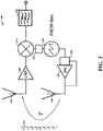
- FIG. 3 shows a radar apparatus 300, in accordance with the present disclosure.
- the apparatus 300 includes an FMCW generator 310, an injection locking circuit 320, and an amplifier 330 that operate together to generate and transmit a radar signal via antenna 340.
- the apparatus includes receiver circuitry for receiving reflections of the transmitted radar signals, including an antenna 342 and amplifier 360.
- the mixer 370 mixes an amplified version of the received reflections from amplifier 360 with the FMCW signal, and may provide an output to circuitry 380 for processing in determining distance to an object 390.
- Phase locking circuitry 350 may be implemented and operate to provide phase locking with respect to the mixer 370.
- the injection locking circuit 320 operates to adjust the phase of the an output signal from the amplifier 330, based on a phase mismatch between the injection signal and an output of the amplifier 330.
- Such an approach may involve, for example, mixing the output of the amplifier 330 with the injection signal, detecting the presence or absence of a phase lock, and adjusting a tuning input (e.g., a tuning voltage applied to a varactor) for modifying the generation of the output signal from amplifier 330.
- a tuning input e.g., a tuning voltage applied to a varactor
- an apparatus includes a plurality of injection-locking circuits configured to receive an injection signal, each injection-locking circuit including a mixer and a lock-detection circuit.
- the lock-detection circuit detects a lock-status relationship between the injection signal and a signal output from the injection-locking circuit.
- a phase/magnitude of the injection signal is adjusted.
- transmission of an FM continuous wave (FMCW) chirp signal is facilitated.
- FMCW FM continuous wave
- circuits or circuitry which may be illustrated as or using terms such as blocks, modules, device, system, unit, controller, generator, oscillator, detector, mixer and/or other circuit-type depictions (e.g., reference numerals 150, 160 and 170 of Figure 1 may depict a block/module as described herein).
- circuits or circuitry are used together with other components to exemplify how certain embodiments may be carried out in the form or structures, steps, functions, operations, or activities.
- one or more modules are discrete logic circuits or programmable logic circuits configured and arranged for implementing these operations/activities, as may be carried out in the approaches shown in the Figures.
- a programmable circuit is one or more computer circuits, including memory circuitry for storing and accessing a program to be executed as a set (or sets) of instructions (and/or to be used as configuration data to define how the programmable circuit is to perform), and an algorithm or process as described herein in connection with the tuning of an injection signal, and is used by such a programmable circuit to perform the related steps, functions, operations, and activities.
- the instructions (and/or configuration data) can be configured for implementation in logic circuitry, with the instructions (whether characterized in the form of object code, firmware or software) stored in and accessible from a memory (circuit).
- a memory e.g., a "first [type of structure]”
- the instructions might be replaced with terms such as ["circuit", “circuitry” and others]
- the adjectives "first” and “second” or “receiver” may not necessarily be used to connote any description of the structure or to provide any substantive meaning; rather, such adjectives are merely used for English-language antecedence to differentiate one such similarly-named structure from another similarly-named structure (e.g., "first circuit configured to adjust" is interpreted as “circuit configured to adjust").
- the terminology is used for notational convenience only and that in actual use the disclosed structures may be oriented different
- Figure 1A may be implemented separately, such as a separate phase-adjusting apparatus implemented with the circuitry in block 170 and mixer 140, as useful with a variety of types of injection locking.
- Block 170 may also be implemented with the mixer 140 and injection-locking circuitry 111 as a separate embodiment, also implementable with different types of injection locking.
- methods as exemplified in the Figures may involve steps carried out in various orders, with one or more aspects of the embodiments herein retained, or may involve fewer or more steps.
- a feedback circuit as shown with Figure 1A can be utilized with a variety of injection locking circuits, such as those shown in Figure 3 .
- the apparatus shown in Figure 3 can be implemented for non-radar functions, such as with a variety of other types of signaling approaches in which an injection signal is utilized. Such modifications do not depart from the true spirit and scope of various aspects of the disclosure, including aspects set forth in the claims.
Landscapes
- Engineering & Computer Science (AREA)
- Radar, Positioning & Navigation (AREA)
- Remote Sensing (AREA)
- Computer Networks & Wireless Communication (AREA)
- Physics & Mathematics (AREA)
- General Physics & Mathematics (AREA)
- Signal Processing (AREA)
- Radar Systems Or Details Thereof (AREA)
- Stabilization Of Oscillater, Synchronisation, Frequency Synthesizers (AREA)
Applications Claiming Priority (1)
| Application Number | Priority Date | Filing Date | Title |
|---|---|---|---|
| US16/521,120 US11372095B2 (en) | 2019-07-24 | 2019-07-24 | Phase-adjustable injection-locking |
Publications (1)
| Publication Number | Publication Date |
|---|---|
| EP3770629A1 true EP3770629A1 (fr) | 2021-01-27 |
Family
ID=71620181
Family Applications (1)
| Application Number | Title | Priority Date | Filing Date |
|---|---|---|---|
| EP20185767.9A Pending EP3770629A1 (fr) | 2019-07-24 | 2020-07-14 | Verrouillage par injection à phase réglable |
Country Status (3)
| Country | Link |
|---|---|
| US (1) | US11372095B2 (fr) |
| EP (1) | EP3770629A1 (fr) |
| CN (1) | CN112311392B (fr) |
Families Citing this family (2)
| Publication number | Priority date | Publication date | Assignee | Title |
|---|---|---|---|---|
| TWI743570B (zh) * | 2019-10-09 | 2021-10-21 | 國立中山大學 | 多目標生理徵象偵測器及其偵測方法 |
| TWI723824B (zh) * | 2020-03-30 | 2021-04-01 | 國立高雄科技大學 | 無線鎖頻迴路之生理感測雷達 |
Citations (4)
| Publication number | Priority date | Publication date | Assignee | Title |
|---|---|---|---|---|
| JP2011247598A (ja) * | 2010-05-21 | 2011-12-08 | Mitsubishi Electric Corp | Fmcwレーダ装置の周波数変調回路 |
| US20160344397A1 (en) * | 2015-05-18 | 2016-11-24 | Fujitsu Limited | Lock detection circuit, oscillation source circuit and wireless device |
| EP3203260A1 (fr) * | 2014-10-03 | 2017-08-09 | Mitsubishi Electric Corporation | Circuit de génération de signaux |
| EP3425803A1 (fr) * | 2017-07-07 | 2019-01-09 | Nxp B.V. | Boucle à verrouillage de phase pour générer un signal chirp |
Family Cites Families (6)
| Publication number | Priority date | Publication date | Assignee | Title |
|---|---|---|---|---|
| US9099956B2 (en) | 2011-04-26 | 2015-08-04 | King Abdulaziz City For Science And Technology | Injection locking based power amplifier |
| CN104880706B (zh) * | 2014-02-27 | 2017-12-19 | 北京大学 | 一种基于片上定向耦合器的调频连续波雷达 |
| CN105259535A (zh) * | 2015-09-29 | 2016-01-20 | 西安知几天线技术有限公司 | 车载雷达射频前端的频率源产生方法 |
| EP3258603B1 (fr) * | 2016-06-15 | 2022-11-09 | Nxp B.V. | Boucle à verrouillage de phase avec détecteur de verrouillage/déverrouillage |
| US10598764B2 (en) * | 2017-10-30 | 2020-03-24 | Yekutiel Josefsberg | Radar target detection and imaging system for autonomous vehicles with ultra-low phase noise frequency synthesizer |
| US10205457B1 (en) * | 2018-06-01 | 2019-02-12 | Yekutiel Josefsberg | RADAR target detection system for autonomous vehicles with ultra lowphase noise frequency synthesizer |
-
2019
- 2019-07-24 US US16/521,120 patent/US11372095B2/en active Active
-
2020
- 2020-06-17 CN CN202010554157.4A patent/CN112311392B/zh active Active
- 2020-07-14 EP EP20185767.9A patent/EP3770629A1/fr active Pending
Patent Citations (4)
| Publication number | Priority date | Publication date | Assignee | Title |
|---|---|---|---|---|
| JP2011247598A (ja) * | 2010-05-21 | 2011-12-08 | Mitsubishi Electric Corp | Fmcwレーダ装置の周波数変調回路 |
| EP3203260A1 (fr) * | 2014-10-03 | 2017-08-09 | Mitsubishi Electric Corporation | Circuit de génération de signaux |
| US20160344397A1 (en) * | 2015-05-18 | 2016-11-24 | Fujitsu Limited | Lock detection circuit, oscillation source circuit and wireless device |
| EP3425803A1 (fr) * | 2017-07-07 | 2019-01-09 | Nxp B.V. | Boucle à verrouillage de phase pour générer un signal chirp |
Also Published As
| Publication number | Publication date |
|---|---|
| CN112311392A (zh) | 2021-02-02 |
| CN112311392B (zh) | 2025-09-16 |
| US20210026002A1 (en) | 2021-01-28 |
| US11372095B2 (en) | 2022-06-28 |
Similar Documents
| Publication | Publication Date | Title |
|---|---|---|
| US11860223B2 (en) | Method of generating self-test signals, corresponding circuit and apparatus | |
| US6760577B2 (en) | Alignment methods and apparatus for I/Q phase and amplitude error correction and image rejection improvement | |
| EP2773044B1 (fr) | Circuit électronique, appareil radar et procédé de réalisation d'auto-diagnostic sur appareil radar | |
| EP0370170B1 (fr) | Générateur de signal avec une boucle d'asservissement de phase et de fréquence combinée | |
| US8064848B2 (en) | Transmitter and control method for transmitting and calibrating a phase signal and an amplitude signal | |
| CA2879231C (fr) | Source de signal de bruit a phase ultra basse | |
| EP3770629A1 (fr) | Verrouillage par injection à phase réglable | |
| US4890071A (en) | Signal generator utilizing a combined phase locked and frequency locked loop | |
| US11025257B2 (en) | Devices and methods for generating a broadband frequency signal | |
| KR20000023315A (ko) | 쿼드라춰 출력 오실레이터 장치 | |
| US20030203724A1 (en) | Accurate gain direct modulation (KMOD) using a dual-loop PLL | |
| US8059777B2 (en) | Method and apparatus for generating phase shifted local oscillator signals for a feedback loop on a transmitter | |
| US4110707A (en) | Indirect FM modulation scheme using phase locked loop | |
| CN114401066B (zh) | 一种高精度时频同步信号分发系统与其分发方法 | |
| US11984848B2 (en) | Frequency generator arrangement | |
| US20210181300A1 (en) | Phase shifter generating pulse signals and continuous frequency signals, radar including the same, and transmitter of radar | |
| CN109921789A (zh) | 压控振荡器电路 | |
| US20080284526A1 (en) | Tuning circuit and method | |
| KR20220083277A (ko) | 주파수 도약 확산 스펙트럼 주파수 합성기 | |
| CN112422125A (zh) | 一种捷变频率源 | |
| US12526009B2 (en) | Phase locked loop with decreased recovery time from disabling spread spectrum clock | |
| CN119496507A (zh) | 锁相频率合成方法及装置、电子设备 | |
| US11722289B2 (en) | Phase synchronization circuit and in-phase distribution circuit | |
| JPH11125669A (ja) | パルスレーダ送受信機 | |
| US20120119942A1 (en) | Radar wave transmit/receive device |
Legal Events
| Date | Code | Title | Description |
|---|---|---|---|
| PUAI | Public reference made under article 153(3) epc to a published international application that has entered the european phase |
Free format text: ORIGINAL CODE: 0009012 |
|
| STAA | Information on the status of an ep patent application or granted ep patent |
Free format text: STATUS: THE APPLICATION HAS BEEN PUBLISHED |
|
| AK | Designated contracting states |
Kind code of ref document: A1 Designated state(s): AL AT BE BG CH CY CZ DE DK EE ES FI FR GB GR HR HU IE IS IT LI LT LU LV MC MK MT NL NO PL PT RO RS SE SI SK SM TR |
|
| AX | Request for extension of the european patent |
Extension state: BA ME |
|
| STAA | Information on the status of an ep patent application or granted ep patent |
Free format text: STATUS: REQUEST FOR EXAMINATION WAS MADE |
|
| 17P | Request for examination filed |
Effective date: 20210727 |
|
| RBV | Designated contracting states (corrected) |
Designated state(s): AL AT BE BG CH CY CZ DE DK EE ES FI FR GB GR HR HU IE IS IT LI LT LU LV MC MK MT NL NO PL PT RO RS SE SI SK SM TR |
|
| STAA | Information on the status of an ep patent application or granted ep patent |
Free format text: STATUS: EXAMINATION IS IN PROGRESS |
|
| 17Q | First examination report despatched |
Effective date: 20230328 |