EP3770948A1 - Solution de traitement et procédé de traitement - Google Patents
Solution de traitement et procédé de traitement Download PDFInfo
- Publication number
- EP3770948A1 EP3770948A1 EP18910789.9A EP18910789A EP3770948A1 EP 3770948 A1 EP3770948 A1 EP 3770948A1 EP 18910789 A EP18910789 A EP 18910789A EP 3770948 A1 EP3770948 A1 EP 3770948A1
- Authority
- EP
- European Patent Office
- Prior art keywords
- treatment solution
- byproduct
- treatment
- hydroxide
- solution according
- Prior art date
- Legal status (The legal status is an assumption and is not a legal conclusion. Google has not performed a legal analysis and makes no representation as to the accuracy of the status listed.)
- Pending
Links
Images



Classifications
-
- A—HUMAN NECESSITIES
- A62—LIFE-SAVING; FIRE-FIGHTING
- A62D—CHEMICAL MEANS FOR EXTINGUISHING FIRES OR FOR COMBATING OR PROTECTING AGAINST HARMFUL CHEMICAL AGENTS; CHEMICAL MATERIALS FOR USE IN BREATHING APPARATUS
- A62D3/00—Processes for making harmful chemical substances harmless or less harmful, by effecting a chemical change in the substances
- A62D3/10—Processes for making harmful chemical substances harmless or less harmful, by effecting a chemical change in the substances by subjecting to electric or wave energy or particle or ionizing radiation
- A62D3/13—Processes for making harmful chemical substances harmless or less harmful, by effecting a chemical change in the substances by subjecting to electric or wave energy or particle or ionizing radiation to sonic energy
-
- C—CHEMISTRY; METALLURGY
- C23—COATING METALLIC MATERIAL; COATING MATERIAL WITH METALLIC MATERIAL; CHEMICAL SURFACE TREATMENT; DIFFUSION TREATMENT OF METALLIC MATERIAL; COATING BY VACUUM EVAPORATION, BY SPUTTERING, BY ION IMPLANTATION OR BY CHEMICAL VAPOUR DEPOSITION, IN GENERAL; INHIBITING CORROSION OF METALLIC MATERIAL OR INCRUSTATION IN GENERAL
- C23C—COATING METALLIC MATERIAL; COATING MATERIAL WITH METALLIC MATERIAL; SURFACE TREATMENT OF METALLIC MATERIAL BY DIFFUSION INTO THE SURFACE, BY CHEMICAL CONVERSION OR SUBSTITUTION; COATING BY VACUUM EVAPORATION, BY SPUTTERING, BY ION IMPLANTATION OR BY CHEMICAL VAPOUR DEPOSITION, IN GENERAL
- C23C16/00—Chemical coating by decomposition of gaseous compounds, without leaving reaction products of surface material in the coating, i.e. chemical vapour deposition [CVD] processes
- C23C16/22—Chemical coating by decomposition of gaseous compounds, without leaving reaction products of surface material in the coating, i.e. chemical vapour deposition [CVD] processes characterised by the deposition of inorganic material, other than metallic material
- C23C16/30—Deposition of compounds, mixtures or solid solutions, e.g. borides, carbides, nitrides
-
- A—HUMAN NECESSITIES
- A62—LIFE-SAVING; FIRE-FIGHTING
- A62D—CHEMICAL MEANS FOR EXTINGUISHING FIRES OR FOR COMBATING OR PROTECTING AGAINST HARMFUL CHEMICAL AGENTS; CHEMICAL MATERIALS FOR USE IN BREATHING APPARATUS
- A62D3/00—Processes for making harmful chemical substances harmless or less harmful, by effecting a chemical change in the substances
- A62D3/30—Processes for making harmful chemical substances harmless or less harmful, by effecting a chemical change in the substances by reacting with chemical agents
- A62D3/36—Detoxification by using acid or alkaline reagents
-
- C—CHEMISTRY; METALLURGY
- C23—COATING METALLIC MATERIAL; COATING MATERIAL WITH METALLIC MATERIAL; CHEMICAL SURFACE TREATMENT; DIFFUSION TREATMENT OF METALLIC MATERIAL; COATING BY VACUUM EVAPORATION, BY SPUTTERING, BY ION IMPLANTATION OR BY CHEMICAL VAPOUR DEPOSITION, IN GENERAL; INHIBITING CORROSION OF METALLIC MATERIAL OR INCRUSTATION IN GENERAL
- C23C—COATING METALLIC MATERIAL; COATING MATERIAL WITH METALLIC MATERIAL; SURFACE TREATMENT OF METALLIC MATERIAL BY DIFFUSION INTO THE SURFACE, BY CHEMICAL CONVERSION OR SUBSTITUTION; COATING BY VACUUM EVAPORATION, BY SPUTTERING, BY ION IMPLANTATION OR BY CHEMICAL VAPOUR DEPOSITION, IN GENERAL
- C23C16/00—Chemical coating by decomposition of gaseous compounds, without leaving reaction products of surface material in the coating, i.e. chemical vapour deposition [CVD] processes
- C23C16/22—Chemical coating by decomposition of gaseous compounds, without leaving reaction products of surface material in the coating, i.e. chemical vapour deposition [CVD] processes characterised by the deposition of inorganic material, other than metallic material
- C23C16/24—Deposition of silicon only
-
- C—CHEMISTRY; METALLURGY
- C23—COATING METALLIC MATERIAL; COATING MATERIAL WITH METALLIC MATERIAL; CHEMICAL SURFACE TREATMENT; DIFFUSION TREATMENT OF METALLIC MATERIAL; COATING BY VACUUM EVAPORATION, BY SPUTTERING, BY ION IMPLANTATION OR BY CHEMICAL VAPOUR DEPOSITION, IN GENERAL; INHIBITING CORROSION OF METALLIC MATERIAL OR INCRUSTATION IN GENERAL
- C23C—COATING METALLIC MATERIAL; COATING MATERIAL WITH METALLIC MATERIAL; SURFACE TREATMENT OF METALLIC MATERIAL BY DIFFUSION INTO THE SURFACE, BY CHEMICAL CONVERSION OR SUBSTITUTION; COATING BY VACUUM EVAPORATION, BY SPUTTERING, BY ION IMPLANTATION OR BY CHEMICAL VAPOUR DEPOSITION, IN GENERAL
- C23C16/00—Chemical coating by decomposition of gaseous compounds, without leaving reaction products of surface material in the coating, i.e. chemical vapour deposition [CVD] processes
- C23C16/44—Chemical coating by decomposition of gaseous compounds, without leaving reaction products of surface material in the coating, i.e. chemical vapour deposition [CVD] processes characterised by the method of coating
- C23C16/4412—Details relating to the exhausts, e.g. pumps, filters, scrubbers, particle traps
-
- C—CHEMISTRY; METALLURGY
- C23—COATING METALLIC MATERIAL; COATING MATERIAL WITH METALLIC MATERIAL; CHEMICAL SURFACE TREATMENT; DIFFUSION TREATMENT OF METALLIC MATERIAL; COATING BY VACUUM EVAPORATION, BY SPUTTERING, BY ION IMPLANTATION OR BY CHEMICAL VAPOUR DEPOSITION, IN GENERAL; INHIBITING CORROSION OF METALLIC MATERIAL OR INCRUSTATION IN GENERAL
- C23C—COATING METALLIC MATERIAL; COATING MATERIAL WITH METALLIC MATERIAL; SURFACE TREATMENT OF METALLIC MATERIAL BY DIFFUSION INTO THE SURFACE, BY CHEMICAL CONVERSION OR SUBSTITUTION; COATING BY VACUUM EVAPORATION, BY SPUTTERING, BY ION IMPLANTATION OR BY CHEMICAL VAPOUR DEPOSITION, IN GENERAL
- C23C16/00—Chemical coating by decomposition of gaseous compounds, without leaving reaction products of surface material in the coating, i.e. chemical vapour deposition [CVD] processes
- C23C16/56—After-treatment
-
- C—CHEMISTRY; METALLURGY
- C30—CRYSTAL GROWTH
- C30B—SINGLE-CRYSTAL GROWTH; UNIDIRECTIONAL SOLIDIFICATION OF EUTECTIC MATERIAL OR UNIDIRECTIONAL DEMIXING OF EUTECTOID MATERIAL; REFINING BY ZONE-MELTING OF MATERIAL; PRODUCTION OF A HOMOGENEOUS POLYCRYSTALLINE MATERIAL WITH DEFINED STRUCTURE; SINGLE CRYSTALS OR HOMOGENEOUS POLYCRYSTALLINE MATERIAL WITH DEFINED STRUCTURE; AFTER-TREATMENT OF SINGLE CRYSTALS OR A HOMOGENEOUS POLYCRYSTALLINE MATERIAL WITH DEFINED STRUCTURE; APPARATUS THEREFOR
- C30B19/00—Liquid-phase epitaxial-layer growth
- C30B19/10—Controlling or regulating
-
- C—CHEMISTRY; METALLURGY
- C30—CRYSTAL GROWTH
- C30B—SINGLE-CRYSTAL GROWTH; UNIDIRECTIONAL SOLIDIFICATION OF EUTECTIC MATERIAL OR UNIDIRECTIONAL DEMIXING OF EUTECTOID MATERIAL; REFINING BY ZONE-MELTING OF MATERIAL; PRODUCTION OF A HOMOGENEOUS POLYCRYSTALLINE MATERIAL WITH DEFINED STRUCTURE; SINGLE CRYSTALS OR HOMOGENEOUS POLYCRYSTALLINE MATERIAL WITH DEFINED STRUCTURE; AFTER-TREATMENT OF SINGLE CRYSTALS OR A HOMOGENEOUS POLYCRYSTALLINE MATERIAL WITH DEFINED STRUCTURE; APPARATUS THEREFOR
- C30B19/00—Liquid-phase epitaxial-layer growth
- C30B19/12—Liquid-phase epitaxial-layer growth characterised by the substrate
-
- C—CHEMISTRY; METALLURGY
- C30—CRYSTAL GROWTH
- C30B—SINGLE-CRYSTAL GROWTH; UNIDIRECTIONAL SOLIDIFICATION OF EUTECTIC MATERIAL OR UNIDIRECTIONAL DEMIXING OF EUTECTOID MATERIAL; REFINING BY ZONE-MELTING OF MATERIAL; PRODUCTION OF A HOMOGENEOUS POLYCRYSTALLINE MATERIAL WITH DEFINED STRUCTURE; SINGLE CRYSTALS OR HOMOGENEOUS POLYCRYSTALLINE MATERIAL WITH DEFINED STRUCTURE; AFTER-TREATMENT OF SINGLE CRYSTALS OR A HOMOGENEOUS POLYCRYSTALLINE MATERIAL WITH DEFINED STRUCTURE; APPARATUS THEREFOR
- C30B25/00—Single-crystal growth by chemical reaction of reactive gases, e.g. chemical vapour-deposition growth
- C30B25/02—Epitaxial-layer growth
-
- C—CHEMISTRY; METALLURGY
- C30—CRYSTAL GROWTH
- C30B—SINGLE-CRYSTAL GROWTH; UNIDIRECTIONAL SOLIDIFICATION OF EUTECTIC MATERIAL OR UNIDIRECTIONAL DEMIXING OF EUTECTOID MATERIAL; REFINING BY ZONE-MELTING OF MATERIAL; PRODUCTION OF A HOMOGENEOUS POLYCRYSTALLINE MATERIAL WITH DEFINED STRUCTURE; SINGLE CRYSTALS OR HOMOGENEOUS POLYCRYSTALLINE MATERIAL WITH DEFINED STRUCTURE; AFTER-TREATMENT OF SINGLE CRYSTALS OR A HOMOGENEOUS POLYCRYSTALLINE MATERIAL WITH DEFINED STRUCTURE; APPARATUS THEREFOR
- C30B29/00—Single crystals or homogeneous polycrystalline material with defined structure characterised by the material or by their shape
- C30B29/02—Elements
- C30B29/06—Silicon
-
- C—CHEMISTRY; METALLURGY
- C30—CRYSTAL GROWTH
- C30B—SINGLE-CRYSTAL GROWTH; UNIDIRECTIONAL SOLIDIFICATION OF EUTECTIC MATERIAL OR UNIDIRECTIONAL DEMIXING OF EUTECTOID MATERIAL; REFINING BY ZONE-MELTING OF MATERIAL; PRODUCTION OF A HOMOGENEOUS POLYCRYSTALLINE MATERIAL WITH DEFINED STRUCTURE; SINGLE CRYSTALS OR HOMOGENEOUS POLYCRYSTALLINE MATERIAL WITH DEFINED STRUCTURE; AFTER-TREATMENT OF SINGLE CRYSTALS OR A HOMOGENEOUS POLYCRYSTALLINE MATERIAL WITH DEFINED STRUCTURE; APPARATUS THEREFOR
- C30B33/00—After-treatment of single crystals or homogeneous polycrystalline material with defined structure
-
- H—ELECTRICITY
- H10—SEMICONDUCTOR DEVICES; ELECTRIC SOLID-STATE DEVICES NOT OTHERWISE PROVIDED FOR
- H10P—GENERIC PROCESSES OR APPARATUS FOR THE MANUFACTURE OR TREATMENT OF DEVICES COVERED BY CLASS H10
- H10P72/00—Handling or holding of wafers, substrates or devices during manufacture or treatment thereof
- H10P72/04—Apparatus for manufacture or treatment
- H10P72/0402—Apparatus for fluid treatment
-
- A—HUMAN NECESSITIES
- A62—LIFE-SAVING; FIRE-FIGHTING
- A62D—CHEMICAL MEANS FOR EXTINGUISHING FIRES OR FOR COMBATING OR PROTECTING AGAINST HARMFUL CHEMICAL AGENTS; CHEMICAL MATERIALS FOR USE IN BREATHING APPARATUS
- A62D2101/00—Harmful chemical substances made harmless, or less harmful, by effecting chemical change
- A62D2101/08—Toxic combustion residues, e.g. toxic substances contained in fly ash from waste incineration
-
- A—HUMAN NECESSITIES
- A62—LIFE-SAVING; FIRE-FIGHTING
- A62D—CHEMICAL MEANS FOR EXTINGUISHING FIRES OR FOR COMBATING OR PROTECTING AGAINST HARMFUL CHEMICAL AGENTS; CHEMICAL MATERIALS FOR USE IN BREATHING APPARATUS
- A62D2101/00—Harmful chemical substances made harmless, or less harmful, by effecting chemical change
- A62D2101/20—Organic substances
- A62D2101/22—Organic substances containing halogen
-
- A—HUMAN NECESSITIES
- A62—LIFE-SAVING; FIRE-FIGHTING
- A62D—CHEMICAL MEANS FOR EXTINGUISHING FIRES OR FOR COMBATING OR PROTECTING AGAINST HARMFUL CHEMICAL AGENTS; CHEMICAL MATERIALS FOR USE IN BREATHING APPARATUS
- A62D2101/00—Harmful chemical substances made harmless, or less harmful, by effecting chemical change
- A62D2101/40—Inorganic substances
Definitions
- Embodiments described herein relate generally to treatment solutions and treatment methods.
- Semiconductor silicon substrates are widely used as materials for forming various electronic circuits.
- a film including a silicon-containing material may be formed on the semiconductor silicon substrate in order to facilitate the formation of an electronic circuit.
- an epitaxial growth apparatus has been used as an apparatus for forming such a film.
- the epitaxial growth apparatus includes a reaction chamber, a supply pipe connected to the reaction chamber and through which a material gas is supplied, and a discharge pipe connected to the reaction chamber and through which an exhaust gas is discharged.
- the epitaxial growth apparatus places a substrate in the reaction chamber depressurized under inert atmosphere, and has a material gas that is introduced into the reaction chamber react with the heated substrate, thereby forming a film including a silicon-containing material on the substrate.
- a material gas for example, a hydrogen gas which includes a compound including silicon and chlorine is used.
- the material gas introduced into the reaction chamber is discharged as the exhaust gas to the outside of the apparatus through the discharge pipe.
- the exhaust gas may contain the compound including silicon and chlorine.
- the temperature in the reaction chamber is significantly higher than that in the discharge pipe. Therefore, the compound including silicon and chlorine contained in the exhaust gas discharged into the discharge pipe may be cooled inside the discharge pipe and precipitated as a byproduct.
- the byproduct also referred to as "oily silane”
- An object of an embodiment is to provide a treatment solution and a treatment method that make it possible to treat a byproduct stemming from the process of depositing a silicon-containing material on a member using a gas which includes silicon and halogen.
- a treatment solution for treating a byproduct stemming from a process of depositing a silicon-containing material on a member using a gas which includes silicon and halogen includes at least one of an inorganic base or an organic base.
- the treatment solution is basic.
- a treatment method using the treatment solution according to the embodiment includes making the byproduct come into contact with the treatment solution.
- Patent Document 1 the main component of the above-described byproduct has been assumed to be a chlorosilane polymer.
- the byproduct is highly reactive to water and oxygen, no method for directly analyzing the byproduct itself has been established.
- the present inventors After intensive studies, the present inventors have established a method for directly analyzing the byproduct itself, and have consequently found the main component of the byproduct to be chlorosilanes having a cyclic structure. The present invention is based on this finding.
- a treatment solution according to an embodiment is for treating a byproduct stemming from a process of depositing a silicon-containing material on a member using a gas which includes silicon and chlorine.
- the treatment solution contains at least one of an inorganic base or an organic base.
- the treatment solution according to the embodiment is basic.
- the byproduct may include chlorosilanes having a cyclic structure.
- the chlorosilanes having a cyclic structure have a thermodynamically stable structure. Therefore, the chlorosilanes having a cyclic structure do not change in quality under inert gas atmosphere. However, the chlorosilanes having a cyclic structure may rapidly react with water or oxygen to turn into a more explosive substance.
- the present inventors have found that treatment of the chlorosilanes having a cyclic structure collected under inert atmosphere with the basic treatment solution renders them harmless in a highly safe manner.
- the treatment solution according to the embodiment can also be referred to as a "treatment solution for treating chlorosilanes having a cyclic structure".
- Using the treatment solution according to the embodiment can render the byproduct harmless in a highly safe manner.
- FIG. 1 is a perspective view schematically showing an example epitaxial growth apparatus.
- the epitaxial growth apparatus 1 shown in FIG. 1 includes an apparatus main body 10, an abatement apparatus 20, and a connection portion 30.
- the apparatus main body 10 includes a housing 11, a reaction chamber 12, a discharge pipe 13, and a supply pipe (not shown).
- the reaction chamber 12, the discharge pipe 13, and the supply pipe are housed in the housing 11.
- One end of the supply pipe is connected to the reaction chamber 12.
- the other end of the supply pipe is connected to a material-gas supply device (not shown).
- the discharge pipe 13 includes pipes 131 to 135.
- One end of the pipe 131 is connected to the reaction chamber 12.
- the other end of the pipe 131 is connected to one end of the pipe 132.
- the pipe 132 includes a chamber isolation valve (CIV).
- the other end of the pipe 132 is connected to one end of the pipe 133.
- the pipe 133 includes a pressure control valve (PCV).
- PCV pressure control valve
- the other end of the pipe 133 is connected to one end of the pipe 134.
- the other end of the pipe 134 is connected to one end of the pipe 135.
- the other end of the pipe 135 is connected to one end of the connection portion 30.
- the connection portion 30 includes a pipe 31 and a pipe 32. One end of the pipe 31 is connected to the other end of the pipe 135. The other end of the pipe 31 is connected to one end of the pipe 32. The other end of the pipe 32 is connected to the abatement device 20.
- a material gas is discharged from the material-gas supply device and introduced into the reaction chamber 12 through the supply pipe.
- the material gas is a gas which includes silicon and chlorine.
- the gas which includes silicon and chlorine is, for example, a gas having hydrogen gas mixed with a compound including silicon and chlorine.
- the concentration of hydrogen in the mixed gas is, for example, 95 vol% or more.
- the compound including silicon and chlorine is, for example, dichlorosilane (SiH 2 Cl 2 ), trichlorosilane (SiHCl 3 ), tetrachlorosilane (SiCl 4 ), or a mixture thereof.
- the mixed gas may contain at least one of monosilane (SiH 4 ) or hydrochloric acid (HCl).
- a substrate is placed in the reaction chamber 12 under reduced pressure, and then heated to a temperature equal to or higher than that for the reaction with the material gas.
- An example reaction temperature is 600 °C or more, and another example reaction temperature is 1000 °C or more.
- a monocrystalline or polycrystalline silicon-containing film is formed on the substrate through a thermochemical reaction.
- the substrate is, for example, a monocrystalline silicon substrate.
- the exhaust gas discharged from the reaction chamber 12 is introduced into the abatement device 20 via the discharge path formed of the discharge pipe 13 and the connection portion 30.
- the exhaust gas can contain the compound including silicon and chlorine which is contained in the material gas but has not been deposited on the substrate, monosilane, hydrogen chloride, etc.
- the exhaust gas is burnt in the abatement device 20 and rendered harmless.
- the byproduct may precipitate in part of the discharge pipe 13 and part of the connection portion 30.
- the byproduct is considered to be a solid or liquid formed by polymerizing components contained in the above-described exhaust gas.
- the byproduct tends to precipitate in the vicinity of the pipe 134 of the discharge pipe 13.
- the temperature of the exhaust gas is sufficiently high, and the polymer is thus considered to precipitate only minimally.
- the connection portion located far from the reaction chamber 12, the amount of raw material components for the byproduct in the exhaust gas is small, and the byproduct is considered to be produced in minimal quantities only.
- the byproduct is considered to include cyclic chlorosilanes.
- the fact that the byproduct contains cyclic chlorosilanes can be presumed by the following method.
- the discharge pipe 13 of the epitaxial growth apparatus 1 is disassembled to remove the pipe to which the byproduct adheres.
- a curved pipe located downstream of the pressure control valve PCV in the flow direction of the exhaust gas is removed.
- both ends of the removed pipe are closed. This operation is performed under inert atmosphere such as nitrogen (N2) gas.
- the removed pipe is transferred into a glove box purged with an inert gas such as nitrogen gas.
- an inert gas such as nitrogen gas.
- the byproduct is collected from the pipe, and analysis samples for use in nuclear magnetic resonance (NMR) spectroscopy and mass spectrometry (MS), respectively, are prepared.
- the atmosphere in the glove box is preferably an argon atmosphere with a moisture concentration of 1 ppm or less and an oxygen concentration of 10 ppm or less.
- VAC101965OMNI-LAB STCH-A manufactured by VAC, Inc. is used as the glove box.
- each of the samples is placed in, for example, a container made of resin which when subsequently in the state of being placed in a sealed container is transferred from the glove box to the analyzer.
- caution is taken not to bring the sample into contact with oxygen and water.
- quick handling should be executed.
- the byproduct is analyzed by a nuclear magnetic resonance (NMR) method.
- NMR nuclear magnetic resonance
- an analysis sample for example, a mixture having 0.2 g of the byproduct mixed with 2 mL of dehydrated heavy toluene (manufactured by Kanto Chemical Co., Inc.: Product No. 21744-1A) and then left for four hours is used.
- this mixture is dispensed into a sample tube with a J. YOUNG valve (S-5-600-JY-8) manufactured by HARUNA Inc.
- the NMR sample tube is set in an NMR spectrometer, and a 29 Si NMR spectrum is measured.
- the NMR spectrometer for example, JNM-ECA800 manufactured by JEOL Ltd. can be used.
- the number of times of integration is set to 3500, and the measurement range is set to -500 to 500 ppm.
- the byproduct is analyzed by mass spectrometry (MS) to obtain a mass spectrum.
- MS mass spectrometry
- the analysis sample for example, a solution obtained by dissolving the byproduct in toluene subjected to degassing and a dehydration treatment is used. The concentration of the byproduct in the solution is 5 mass%, and the water content is 0.6 ppm or less.
- a purification apparatus VAC SOLVENT PURIFIER 103991 manufactured by VAC, Inc. is used.
- the mass spectrometer for example, a solariX 9.4T manufactured by Bruker Daltonics is used.
- an ionization method an APCI (Atmospheric Pressure Chemical Ionization) method is used.
- the number of times of integration is set to 300, and the measurement range is set to 100 to 2000 m/z.
- the byproduct can be presumed to contain chlorosilanes having a cyclic structure.
- Requirement (1) In the 29 Si NMR spectrum, a signal with the greatest relative intensity appears at a position of -0.4 ppm.
- FIG. 2 is a graph showing an example 29 Si NMR spectrum of the byproduct.
- the horizontal axis indicates a chemical shift (ppm), and the vertical axis indicates a relative intensity.
- the signal with the greatest relative intensity is detected at the position of -0.4 ppm.
- No signal is detected in the range of -80 to - 40 ppm.
- a signal appearing at the position of -0.4 ppm is presumed to belong to a SiCl 3 unit or a SiCl 2 unit.
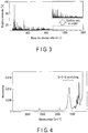
- Requirement (2) In the mass spectrum, signals belonging to (SiCl 2 ) n are detected over a mass-to-charge ratio range of about 0 to 1500 m/z.
- FIG. 3 is a graph showing an example mass spectrum of the byproduct.
- the horizontal axis indicates a mass-to-charge ratio (m/z)
- the vertical axis indicates a relative intensity (%).
- the upper right portion is a view of the mass spectrum part with a high mass-to-charge ratio enlarged in the vertical axis direction.
- signals belonging to (SiCl 2 ) n are detected in a range of 391 to 1545 m/z.
- the byproduct contains a substance having a molecular framework constituted by a SiCl 2 unit and a SiCl 3 unit, as a main component.
- the byproduct contains a substance having a mass ratio between silicon and chlorine of 1:2.
- the composition formula of such a substance is considered (SiCl 2 ) n , where n is 3 to 15.
- (SiCl 2 ) n is expressed as, for example, Si 6 Cl 12 , Si 14 Cl 28 , and Si 15 Cl 30 .
- chlorosilanes having a cyclic structure are considered to be represented by any one of the following structural formulae (a) to (d).
- the byproduct is considered to be a mixture of chlorosilanes having a cyclic structure represented by the above structural formulae (a) to (d).
- the chlorosilanes having a cyclic structure represented by the above structural formulae are thermodynamically stable.
- the above chlorosilanes having a cyclic structure have a Si-Si bond and a Si-Cl bond. These bonds display high reactivity to water and oxygen. Therefore, the chlorosilanes having a cyclic structure are considered to rapidly react with water and oxygen under air atmosphere. Such chlorosilanes are considered to further react with water and oxygen to produce explosive substances.
- Chlorosilanes having no cyclic structure are considered to be, for example, chain chlorosilanes.
- the explosive substances are considered to be, for example, silyl ethers, siloxanes, silanols or mixtures thereof.
- the byproduct may include not only the chlorosilanes having a cyclic structure but also siloxanes, chain chlorosilanes, silica, or the like.
- the siloxanes include a Si-O or Si-O-Si bond.
- the byproduct including the siloxanes can be confirmed by Fourier transform infrared (FT-IR) spectroscopy. That is, when a peak belonging to Si-O-Si is detected in the infrared spectrum of the byproduct, the byproduct can be presumed to contain siloxanes. In the infrared spectrum, the peak belonging to Si-O-Si is detected, for example, in a range of 900 to 1700cm -1 , and according to another example, is detected in a range of 900 to 1300 cm -1 .
- FT-IR Fourier transform infrared
- a byproduct is collected in the same manner as described above.
- an infrared spectrum of the byproduct is obtained by a single-reflection attenuated total reflection (ATR) method.
- the infrared spectroscopic analysis is performed with an infrared spectroscopic analyzer placed in a glove box purged with nitrogen.
- the infrared spectroscopic analyzer for example, ALPHA manufactured by Bruker Optics Inc. is used.
- the ATR crystal germanium (Ge) is used.
- the analysis conditions for example, the incident angle is set to 45°, the number of integrations is set to 512, the measurement range is set to 500 to 4000 cm -1 , and the resolution is set to 4 cm -1 .
- FIG. 4 is a graph showing an example infrared spectrum of the byproduct.
- the horizontal axis indicates a wavenumber (cm -1 )
- the vertical axis indicates absorbance.
- a peak belonging to Si-O-Si stretching is detected in the range of 900 to 1700 cm -1 .
- the byproduct including chlorosilanes having a cyclic structure upon coming into contact with the basic treatment solution can decompose without producing an explosive substance. This is because the reaction of the chlorosilanes having a cyclic structure with the basic treatment solution cleaves the Si-Si bond and the Si-Cl bond in the chlorosilanes having a cyclic structure. Thus, the treatment solution after the reaction is almost free from explosive or flammable substances. Further, in this reaction treatment, hydrogen chloride (HCl) can be produced. Therefore, in this reaction treatment, the pH of the treatment solution tends to become low. Use of the basic treatment solution can neutralize the hydrogen chloride, and thus minimize a decrease in the pH of the treatment solution. Therefore, use of the basic treatment solution renders it possible to safely dispose of the treatment solution after the reaction.
- HCl hydrogen chloride
- This treatment method may be divided into 2 stages. That is, first, a pre-treatment that makes the byproduct including the chlorosilanes having a cyclic structure react with water is performed to obtain a mixed solution. Next, the mixed solution is mixed with at least one of an inorganic base or an organic base. This method also can render the byproduct harmless.
- the byproduct is collected preferably under inert atmosphere; and in order to maintain the byproduct under inert atmosphere until immediately before the reaction, the byproduct reacts with the treatment solution preferably under inert atmosphere.
- Managing the byproduct under inert atmosphere renders it possible to prevent not only the inside but also the surface of a cake of the byproduct from reacting with water or oxygen.
- the inert gas is, for example, nitrogen gas, argon gas, or a mixed gas thereof.
- the dew point is preferably - 50 °C or less and the concentration of oxygen is preferably 10 ppm or less.
- the mixture of the byproduct and the treatment solution is preferably subjected to an ultrasonic treatment using an ultrasonic cleaner. That is, using ultrasonic waves to vibrate the byproduct and the treatment solution can enhance the dispersibility of the byproduct in the treatment solution without using a stirring rod or the like.
- the frequency of the ultrasonic waves is preferably 20 kHz or more.
- the byproduct may be deposited on the pipe as a high-viscosity liquid substance. Therefore, in the deposit of the byproduct, the chlorosilanes having a cyclic structure on the surface of the deposit are considered to react with water or oxygen to decompose into those having no cyclic structure upon reacting. On the other hand, the chlorosilanes having a cyclic structure inside the deposit of the byproduct are less likely to come into contact with water or oxygen, and are considered to have their cyclic structure maintained even under air atmosphere. Therefore, the treatment of the byproduct using the basic treatment solution is also effective under air atmosphere.
- the treatment solution is a basic aqueous solution including at least one of an inorganic base or an organic base.
- a concentration of the inorganic base and the organic base in the treatment solution is, for example, 0.01 mass% to 30 mass%, preferably 0.1 mass% to 10 mass%.
- the inorganic base for example, at least one selected from the group consisting of a metal hydroxide, an alkali metal, a carbonate, a hydrogencarbonate, and a metal oxide is used.
- the metal hydroxide is, for example, lithium hydroxide, sodium hydroxide, potassium hydroxide, rubidium hydroxide, cesium hydroxide, calcium hydroxide, magnesium hydroxide, copper hydroxide, iron hydroxide, zinc hydroxide, aluminum hydroxide, or a mixture thereof.
- the alkali metal is, for example, a single metal that is potassium, a single metal that is lithium, a single metal that is sodium, or a mixture thereof.
- the carbonate is, for example, sodium carbonate, potassium carbonate, ammonium carbonate, potassium carbonate, lithium carbonate, barium carbonate, magnesium carbonate, or a mixture thereof.
- the hydrogencarbonate is, for example, sodium hydrogencarbonate, ammonium hydrogencarbonate, potassium hydrogencarbonate, calcium hydrogencarbonate, or a mixture thereof.
- the metal oxide is, for example, calcium oxide, magnesium oxide, sodium oxide, or a mixture thereof.
- the inorganic base includes, for example, at least one selected from the group consisting of a hydroxide of an alkali metal element, a carbonate of an alkali metal element, a hydrogencarbonate of an alkali metal element, a hydroxide of an alkaline earth metal element, a carbonate of an alkaline earth metal element, and ammonium hydroxide (NH 4 OH) .
- the inorganic base is preferably at least one selected from the group consisting of sodium hydroxide (NaOH), potassium hydroxide (KOH), sodium carbonate (Na 2 CO 3 ), calcium hydroxide (Ca(OH) 2 ), lithium hydroxide (LiOH), sodium hydrogencarbonate (NaHCO 3 ), and ammonium hydroxide (NH 4 OH).
- NaOH sodium hydroxide
- KOH potassium hydroxide
- Na 2 CO 3 calcium hydroxide
- LiOH lithium hydroxide
- NaHCO 3 sodium hydrogencarbonate
- NH 4 OH ammonium hydroxide
- the inorganic base is more preferably at least one selected from the group consisting of potassium hydroxide (KOH), sodium carbonate (Na 2 CO 3 ), lithium hydroxide (LiOH), sodium hydrogencarbonate (NaHCO 3 ), and ammonium hydroxide (NH 4 OH).
- KOH potassium hydroxide
- Na 2 CO 3 sodium carbonate
- LiOH lithium hydroxide
- NaHCO 3 sodium hydrogencarbonate
- NH 4 OH ammonium hydroxide
- organic base for example, at least one selected from the group consisting of an alkylammonium hydroxide, an organometallic compound, a metal alkoxide, an amine, and a heterocyclic amine is used.
- the alkylammonium hydroxide is, for example, tetramethylammonium hydroxide, tetraethylammonium hydroxide, choline hydroxide, or a mixture thereof.
- the organometallic compound is, for example, an organolithium, an organomagnesium, or a mixture thereof.
- the organolithium is, for example, butyllithium, methyllithium, or a mixture thereof.
- the organomagnesium is, for example, butylmagnesium, methylmagnesium, or a mixture thereof.
- the metal alkoxide is, for example, sodium ethoxide, sodium butoxide, potassium ethoxide, potassium butoxide, sodium phenoxide, lithium phenoxide, sodium ethoxide, or a mixture thereof.
- the amine is methylamine, dimethylamine, trimethylamine, triethylamine, ethylenediamine, diethylamine, aniline, or a mixture thereof.
- the heterocyclic amine is pyridine, pyrrolidine, imidazole, piperidine, or a mixture thereof.
- the organic base is preferably at least one selected from the group consisting of sodium phenoxide (C 6 H 5 ONa), 2-hydroxyethyltrimethylammonium hydroxide (choline hydroxide), and tetramethylammonium hydroxide (TMAH).
- sodium phenoxide C 6 H 5 ONa
- 2-hydroxyethyltrimethylammonium hydroxide choline hydroxide
- TMAH tetramethylammonium hydroxide
- water As the solvent of the treatment solution, water is used.
- water pure water, ion-exchanged water, purified water, tap water, or a mixture thereof may be used.
- the pH of the treatment solution is preferably 8 to 14 before and after the treatment.
- the pH of the treatment solution before the treatment is preferably 9 to 14, and more preferably 10 to 14.
- the treatment solution may include an optional component such as a surfactant or a pH buffer in addition to the inorganic base or the organic base.
- the surfactant enhances the dispersibility of the byproduct in the treatment solution and accelerates the treatment.
- concentration of the surfactant in the treatment solution is, for example, 0.01 mass% to 10 mass%, and preferably 0.1 mass% to 1 mass%.
- the surfactant includes, for example, at least one selected from the group consisting of an anionic surfactant, a cationic surfactant, an amphoteric surfactant, and a nonionic surfactant.
- the anionic surfactant is, for example, sodium laurate, sodium stearate, sodium lauryl sulfate, sodium 1-hexanesulfonate, lauryl phosphate, or a mixture thereof.
- the cationic surfactant is, for example, tetramethylammonium chloride, benzalkonium chloride, octyltrimethylammonium chloride, monomethylamine hydrochloride, butylpyridinium chloride, or a mixture thereof.
- amphoteric surfactant is, for example, lauryldimethylaminoacetic acid betaine, cocamidopropyl betaine, sodium lauroyl glutamate, lauryldimethylamine N-oxide, or a mixture thereof.
- the nonionic surfactant is, for example, glycerol laurate, pentaethylene glycol onododecyl ether, polyoxyethylene sorbitan fatty ester, diethanolamide laurate, octylglucoside, cetanol, or a mixture thereof.
- the surfactant preferably includes at least one of benzalkonium chloride or sodium laurate, and more preferably, benzalkonium chloride is used.
- the pH buffer serves to maintain the pH of the treatment solution constant during the treatment of the byproduct. Using the pH buffer can prevent the pH of the solution after the byproduct decomposition treatment from becoming excessively high or low. Thus, through use of the pH buffer, the byproduct can be rendered harmless more safely.
- the concentration of the pH buffer in the treatment solution is, for example, 0.01 mass% to 30 mass%, or preferably 0.1 mass% to 10 mass%.
- pH buffer a mixture of a weak acid and its conjugate base, or a mixture of a weak base and its conjugate acid can be used.
- pH buffer include a mixture of acetic acid (CH 3 COOH) and sodium acetate (CH 3 COONa), a mixture of citric acid and sodium citrate, or a mixture of trishydroxymethylaminomethane (THAM) and ethylenediaminetetraacetic acid (EDTA).
- the treatment solution according to the embodiment described above is basic. Therefore, by using the treatment solution according to the embodiment, the byproduct stemming from the process of depositing the silicon-containing material on the member using the gas which includes silicon and chlorine can be rendered harmless in a safe manner.
- the above-described treatment method and treatment solution can also be applied to a byproduct stemming from a chemical vapor deposition (CVD) method other than the epitaxial growth method.
- the treatment method and the treatment solution can also be applied to a byproduct stemming from a method for synthesizing a silicon-containing material using a gas which includes silicon and chlorine, other than the CVD method. Examples of such a method include production of polycrystalline silicon through reduction due to hydrogen gas which includes trichlorosilane.
- the byproduct may contain halosilanes having a cyclic structure that include a halogen element other than chlorine.
- halosilanes having a cyclic structure may include a Si-Si bond and at least one bond selected from the group consisting of a Si-Cl bond, a Si-Br bond, a Si-F bond, and a Si-I bond.
- the halosilanes having a cyclic structure that may be included in the byproduct may contain at least one of a SiX y group or an X y group.
- y is 1 to 3
- X is at least one selected from the group consisting of Cl, F, Br, and I.
- the halosilanes having a cyclic structure may be included in a byproduct stemming from a process of depositing a silicon-containing material on a member using, for example, a gas which includes silicon and halogen.
- a method that causes the production of the byproduct including the halosilanes having a cyclic structure will be described below, with the epitaxial growth method described with reference to FIG. 1 taken as an example.
- the material gas introduced into the reaction chamber 12 may contain a halogen element other than chlorine. That is, the material gas may be a mixed gas of hydrogen gas and a compound including silicon and a halogen element other than chlorine.
- the compound including silicon and a halogen element other than chlorine is, for example, a compound including silicon and bromine.
- the compound including silicon and bromine is, for example, dibromosilane (SiH 2 Br 2 ), tribromosilane (SiHBr 3 ), tetrabromosilane (SiBr 4 ), or a mixture thereof.
- the mixed gas may contain at least one of monosilane (SiH 4 ) or hydrobromic acid (HBr).
- the material gas which includes the compound containing silicon and the halogen element other than chlorine is used in this manner, a silicon-containing film can be formed on a substrate in the same manner as when a material gas which includes a compound including silicon and chlorine is used.
- the byproduct that may precipitate out at the discharge pipe 13 and the connection portion 30 of the epitaxial growth apparatus 1 may include the halosilanes having a cyclic structure and including the halogen other than chlorine, for example, bromosilanes having a cyclic structure.
- the mixed gas may be a gas having at least one of a compound including a halogen element other than chlorine, or a halogen gas other than chlorine mixed with a compound including silicon and chlorine and hydrogen gas.
- the compound including the halogen element other than chlorine may or may not include silicon.
- the mixed gas may be a gas having at least one of a compound including chlorine, or chlorine gas mixed with a compound including silicon and a halogen element other than chlorine and hydrogen gas.
- the compound including chlorine may or may not include silicon.
- the byproduct that can precipitate out may include at least one compound selected from the group consisting of the chlorosilanes having a cyclic structure, the halosilanes having a cyclic structure and including halogen other than chlorine, and the halosilanes having a cyclic structure and including chlorine and the halogen element other than chlorine.
- the substrate placed in the reaction chamber 12 may be a silicon substrate having a film including the halogen element other than chlorine formed on its surface.
- the halogen element included in the film formed on the surface of the silicon substrate may react with the silicon included in the material gas, which may produce halosilanes.
- the halosilanes are gasified in the reaction chamber 12 and discharged to the discharge pipe 13 together with the exhaust gas. In the discharge pipe 13 or the connection portion 30, the halosilanes are polymerized either with each other or with other components included in the exhaust gas, thereby leading to the possible production of the byproduct.
- the byproduct may include at least one compound selected from the group consisting of the chlorosilanes having a cyclic structure, the halosilanes having a cyclic structure and including the halogen other than chlorine, and the halosilanes having a cyclic structure and including chlorine and the halogen element other than chlorine.
- the substrate placed in the reaction chamber 12 may have the halogen element other than chlorine remaining on its surface.
- hydrofluoric acid HF
- a substrate such as a silicon substrate.
- a substrate may be subjected to a surface treatment, such as etching, with a gas including a halogen element.
- a compound including the halogen element other than chlorine, such as hydrofluoric acid may remain on the surface of the substrate.
- the halogen element inevitably introduced into the reaction chamber 12 reacting with silicon in this manner, the above-described halosilanes are produced, which in turn may produce the byproduct including the halosilanes having a cyclic structure.
- the halosilanes including the halogen other than chlorine and the halosilanes having a cyclic structure and including chlorine and the halogen element other than chlorine, which can be produced in the above manner, are inferred to have properties similar to those of the above-described chlorosilanes having a cyclic structure. Therefore, the halosilanes having a cyclic structure are preferably subjected to a detoxification treatment similar to that for the above-described chlorosilanes having a cyclic structure. It is considered that by making the treatment solution according to the embodiment come into contact with the halosilanes having a cyclic structure, the halosilanes having a cyclic structure can be safely rendered harmless.
- the halosilanes having a cyclic structure are considered to be represented by any one of the following structural formulae (e) to (h).
- X is at least one element selected from the group consisting of F, Cl, Br, and I.
- the structures of the halosilanes having a cyclic structure shown below can be presumed by analyzing the byproduct using the above-described nuclear magnetic resonance (MNR) spectroscopy and mass spectrometry (MS), or the like.
- the byproduct may include siloxanes, chain halosilanes, silica, or the like in addition to the halosilanes having a cyclic structure.
- the halosilanes having a cyclic structure may have a 4-membered cyclic structure, a 5-membered cyclic structure, a 6-membered cyclic structure other than those represented by the structural formulae (e) to (h), a 7-membered cyclic structure, an 8-membered cyclic structure, a multi-membered cyclic structure, or the like, as shown by the following structural formulae (1) to (21).
- X is at least one element selected from the group consisting of F, Cl, Br, and I. Note that the following structural formulae (1-1) to (21-1) respectively show the chlorosilanes of the structural formulae (1) to (21) that take chlorine as the element X.
- the halosilanes having a cyclic structure included in the byproduct may be homocyclic compounds having a silicon ring consisting of silicon, as shown in the above structural formulae (1) to (21), and may also be inorganic cyclic compounds free from carbon as shown in the above structural formulae (1) to (21).
- the byproduct may include a heterocyclic compound made of silicon and oxygen.
- the halosilanes having a chain structure that may be included in the byproduct are represented, for example, by the following structural formulae (22) and (23).
- N is, for example, a positive integer of from 0 to 15.
- X is at least one element selected from the group consisting of F, Cl, Br and I.
- the following structural formulae (22-1) and (23-1) respectively show the chlorosilanes of the structural formulae (22) and (23) that take chlorine as the element X.
- the halosilanes having a chain structure may be a linear compound having no branch as shown in the structural formula (22).
- the halosilanes having a chain structure may be a chain compound having a branch as shown in the structural formula (23). It can be presumed by mass spectrometry that the byproduct includes the halosilanes having a chain structure.
- the byproduct stemming from the process of depositing the silicon-containing material on a member using the gas which includes silicon and halogen may include only the halosilanes having a cyclic structure or only the halosilanes having a chain structure as halosilane, or may include both of the halosilanes having a cyclic structure and the halosilanes having a chain structure.
- the treatment solution according to the embodiment can be used as a treatment solution for treating a substance including a compound having at least one of a siloxane bond or a silanol group.
- the substance including the compound having at least one of a siloxane bond or a silanol group include hydrolysates of the halosilanes having a cyclic structure or a chain structure. That is, the byproduct stemming from the process of depositing the silicon-containing material on a member using the gas which includes silicon and halogen may include the hydrolysate.
- the hydrolysate that may be included in the byproduct can be obtained by making the byproduct including the halosilanes having a cyclic structure or a chain structure come into contact with water or air.
- the hydrolysate may be in the form of a solid.
- the hydrolysate may be in the form of a mass or particulates.
- the hydrolysate may include a compound having at least one of a siloxane bond (Si-O-Si, O-Si-O) or a silanol group (-Si-OH).
- the hydrolysate may also include a hydrasilanol group (-Si(H)OH).
- the hydrolysate having at least one of the siloxane bond or the silanol group can be presumed by nuclear magnetic resonance spectroscopy described below.
- a byproduct is collected in the same manner as described above. Pure water is added into a petri dish including the byproduct in a fume hood under air atmosphere, thereby obtaining a mixture of the byproduct and the pure water.
- the amount of pure water is, for example, 1 mL for 50 mg of the byproduct.
- the pure water is water having a specific resistance of 18.2 M ⁇ cm or more.
- the petri dish is covered with a lid and the mixture is left for 1 hour or more. Thereafter, the lid of the petri dish is removed, and the mixture is left for 24 hours or more at ambient temperature to allow water to volatilize from the mixture.
- the solid thus obtained is pulverized with a spatula made of fluorocarbon resin or the like to obtain powder.
- the powder is dried for 2 hours or more under reduced pressure of 5 Pa or less with a vacuum pump to obtain a measurement sample.
- the measurement sample is dispensed into a 3.2 mm zirconia sample tube (708239971) manufactured by JEOL Ltd.
- This NMR sample tube is set in an NMR spectrometer, and a 29 Si NMR spectrum is measured.
- the NMR spectrometer for example, JNM-ECA800 manufactured by JEOL Ltd. can be used.
- the number of times of integration is set to 4096, and the measurement range is set to -250 to 250 ppm.
- FIG. 5 is a graph showing an example 29 Si NMR spectrum of the hydrolysate of the byproduct.
- the horizontal axis indicates a chemical shift (ppm), and the vertical axis indicates a relative intensity.
- the peak with the greatest relative intensity is detected at a position of -70 ppm.
- halogen elements are fluorine (F), chlorine (Cl), and bromine (Br).
- F fluorine
- Cl chlorine
- Br bromine
- the elemental analysis result obtained for the hydrolysate shows that the abundance ratio of hydrogen is 1 mass% to 10 mass% and the abundance ratio of the halogen elements is 20 mass% or less, it can be said that the amount of halogen in the byproduct has decreased and the amount of hydrogen has increased through the hydrolysis.
- the abundance ratio of hydrogen may be 1 mass% to 4 mass%, and the abundance ratio of the halogen elements may be 1.5 mass% or less.
- the increased hydrogen is considered to be derived from Si-OH bonds.
- the halogen in the byproduct is considered to be substituted by a hydroxyl group through the hydrolysis of the byproduct.
- the hydrolysate consisting of silicon, oxygen, and hydrogen is presumed to have the following structural formulae (24) to (29).
- the compounds shown by the structural formulae (24) to (29) have both the siloxane bond and the silanol group.
- the compounds shown by the structural formulae (24) to (29) are polysilanols having two or more silanol groups.
- the abundance ratio of hydrogen is 2.961 mass%.
- the abundance ratio of hydrogen is 3.82 mass%, the abundance ratio of oxygen is 60.67 mass%, and the abundance ratio of silicon is 35.50 mass%.
- the abundance ratio of hydrogen is 2.88 mass%, the abundance ratio of oxygen is 57.06 mass%, and the abundance ratio of silicon is 40.07 mass%.
- the abundance ratio of hydrogen is 1.65 mass%, the abundance ratio of oxygen is 52.38 mass%, and the abundance ratio of silicon is 45.97 mass%.
- the abundance ratio of hydrogen is 2.63 mass%
- the abundance ratio of oxygen is 48.61 mass%
- the abundance ratio of silicon is 48.76 mass%.
- the abundance ratio of hydrogen is 2.63 mass%
- the abundance ratio of oxygen is 48.61 mass%
- the abundance ratio of silicon is 48.76 mass%.
- the siloxane bond and the Si-Si bond included in the hydrolysate of the byproduct may cause explosiveness or flammability.
- the cyclic siloxane bonds included in the structural formulae (26) to (29), and the cyclic silicon ring included in the structural formulae (28) and (29) upon cleaving can release large energy. Therefore, compounds including these rings are considered to exhibit flammability.
- the siloxane bond and the Si-Si bond can be cleaved, which can render the hydrolysate of the byproduct harmless in a safe manner.
- the treatment solution according to the embodiment described above is basic. Therefore, using the treatment solution according to the embodiment makes it possible to render the byproduct including the halosilanes having a cyclic structure harmless in a safe manner.
- a material gas was introduced into an epitaxial growth apparatus and reacted with a silicon substrate at a temperature of 800 °C to form a monocrystalline silicon film on the silicon substrate.
- a mixed gas having hydrogen gas mixed with dichlorosilane and hydrogen chloride was used as the material gas. The concentration of hydrogen in the mixed gas was 95 vol% or more.
- the pipe of the epitaxial growth apparatus was disassembled under nitrogen atmosphere to collect a byproduct.
- the byproduct was a white creamy liquid.
- the collected byproduct was analyzed by the above-described method, and confirmed to include chlorosilanes having a cyclic structure considered to correspond to any one of the structural formulae (a) to (d), (1-1), (2-1), (12-1), and (14-1).
- treatment solution TS1 a treatment solution obtained by dissolving sodium hydrogencarbonate (NaHCO 3 ) in water was used.
- concentration of sodium hydrogencarbonate in the treatment solution was 10 mass%.
- this treatment solution will be referred to as a "treatment solution TS1".
- the petri dish was removed from the airtight container, and 1.0 mL of the treatment solution TS1 was added to have the byproduct react with the treatment solution TS1. As a result, fine foaming from the byproduct was confirmed.
- This treatment was performed while measuring the temperature of the treatment solution using a thermometer.
- the byproduct was treated in the same manner as described in Example 1, except that a treatment solution TS2 was used instead of the treatment solution TS1.
- a treatment solution TS2 an aqueous solution having sodium hydrogencarbonate mixed with a pH buffer was used.
- a pH buffer a mixture of sodium acetate (CH 3 COONa) and acetic acid (CH 3 COOH) was used.
- the concentration of sodium hydrogencarbonate was 10 mass%
- the concentration of sodium acetate was 1 mass%
- the concentration of acetic acid was 1 mass%.
- the byproduct was treated in the same manner as described in Example 1, except that a treatment solution TS3 was used instead of the treatment solution TS1. As a result, vigorous foaming from the byproduct was confirmed.
- a treatment solution TS3 a solution obtained by dissolving sodium hydroxide (NaOH) in water was used. The concentration of NaOH in the treatment solution TS3 was 10 mass%.
- the byproduct was treated in the same manner as described in Example 1, except that a treatment solution TS4 was used instead of the treatment solution TS1.
- a treatment solution TS4 a solution obtained by dissolving sodium phenoxide (C 6 H 5 ONa) in water was used.
- the concentration of sodium phenoxide in the treatment solution TS4 was 10 mass%.
- the byproduct was treated in the same manner as described in Example 1, except that a treatment solution TS5 was used instead of the treatment solution TS1.
- a treatment solution TS5 a solution obtained by dispersing calcium hydroxide (Ca(OH) 2 ) in water was used.
- the concentration of calcium hydroxide in the treatment solution TS5 was 10 mass%.
- the byproduct was treated in the same manner as described in Example 1, except that a treatment solution TS6 was used instead of the treatment solution TS1. As a result, the byproduct was dispersed in the treatment solution.
- a treatment solution TS6 an aqueous solution having sodium hydroxide mixed with a surfactant was used.
- the surfactant benzalkonium chloride was used. In the treatment solution TS6, the concentration of sodium hydroxide was 10 mass%, and the concentration of benzalkonium chloride was 1 mass%.
- the byproduct was treated in the same manner as described in Example 1, except that handled under inert gas atmosphere so as not to come into contact with oxygen or water.
- the byproduct was treated in the same manner as described in Example 6, except handled under inert gas atmosphere so as not to come into contact with oxygen or water.
- the byproduct was treated in the same manner as described in Example 2, except handled under inert gas atmosphere so as not to come into contact with oxygen or water.
- the byproduct was treated in the same manner as described in Example 1, except that water was used instead of the treatment solution TS1.
- the byproduct was treated in the same manner as described in Example 1, except that a treatment solution TS7 was used instead of the treatment solution TS1.
- a treatment solution TS7 a solution obtained by dissolving hydrogen peroxide (H 2 O 2 ) in water was used.
- the concentration of hydrogen peroxide in the treatment solution TS7 was 10 mass%.
- the byproduct was treated in the same manner as described in Comparative Example 1, except that the bottom of the petri dish was heated to 50 °C with a heater after water was added to the petri dish.
- the byproduct was treated in the same manner as described in Comparative Example 1, except that an ultrasonic treatment was performed using an ultrasonic cleaner after water was added to the petri dish.
- the ultrasonic treatment was performed at a frequency of 28 kHz.
- the byproduct was treated in the same manner as described in Comparative Example 1, except that the mass of the byproduct on the petri dish was pulverized with a spatula after water was added to the petri dish.
- the byproduct was treated in the same manner as described in Example 1, except that a treatment solution TS8 was used instead of the treatment solution TS1.
- a treatment solution TS8 a solution obtained by dissolving benzalkonium chloride in water was used. As a result, the byproduct was dispersed in the treatment solution.
- the byproduct was treated in the same manner as described in Example 1, except that after the treatment solution TS1 was added to the petri dish, an ultrasonic treatment was performed using an ultrasonic cleaner.
- the ultrasonic treatment was performed at a frequency of 28 kHz.
- the byproduct was treated in the same manner as described in Example 5, except that an ultrasonic treatment was performed using an ultrasonic cleaner after the treatment solution TS5 was added to the petri dish.
- the ultrasonic treatment was performed at a frequency of 28 kHz.
- the byproduct was treated in the same manner as described in Example 1, except that a treatment solution TS9 was used instead of the treatment solution TS1.
- a treatment solution TS9 a solution obtained by dissolving tetramethylammonium hydroxide (TMAH) in water was used.
- TMAH tetramethylammonium hydroxide
- the concentration of TMAH in the treatment solution TS9 was 25 mass%.
- the byproduct was treated in the same manner as described in Example 1, except that a treatment solution TS10 was used instead of the treatment solution TS1.
- a treatment solution TS10 a solution obtained by dissolving tetramethylammonium hydroxide (TMAH) in water was used.
- TMAH tetramethylammonium hydroxide
- the concentration of TMAH in the treatment solution TS10 was 5 mass%.
- the byproduct was treated in the same manner as described in Example 1, except that a treatment solution TS11 was used instead of the treatment solution TS1.
- a treatment solution TS11 a solution obtained by dissolving tetramethylammonium hydroxide (TMAH) in water was used.
- the concentration of TMAH in the treatment solution TS11 was 0.26 mass%. As a result, the temperature of the treatment solution during the treatment of the byproduct did not increase.
- the byproduct was treated in the same manner as described in Example 1, except that a treatment solution TS12 was used instead of the treatment solution TS1.
- a treatment solution TS12 a solution obtained by dissolving choline hydroxide in water was used.
- the concentration of choline hydroxide in the treatment solution TS12 was 4 mass%.
- the treatment solution after each test was sufficiently dried in an exhaust booth.
- a small amount of the solids remaining on the petri dish was dispensed into a container made of Steel Special Use Stainless (SUS).
- SUS Steel Special Use Stainless
- the solids were moved on the petri dish with a spatula made of SUS pressed on the solids. Whether or not the solids ignite was visually examined at this time.
- the pHs of the treatment solutions after the treatment were 7 or more, and the solids obtained by drying the treatment solutions after the treatment did not display flammability or explosiveness.
- the pHs of the treatment solutions after the treatment were 1 or less.
- the solids obtained by drying the treatment solutions after the treatment displayed flammability.
- the highest temperature during the treatment was lower and the pH after the treatment was close to neutral when the treatment solution TS1, including NaHCO 3 , or the treatment solution TS4, including C 6 H 5 ONa, was used than when the treatment solution TS3, including NaOH, and the treatment solution TS5, including Ca(OH) 2 , were used.
- a monocrystalline silicon film was formed under the same conditions as those described in Example 1 except that the reaction temperature was changed from 800 °C to 1000 °C.
- the pipe of the epitaxial growth apparatus was disassembled under nitrogen atmosphere to collect a byproduct.
- the byproduct was in the form of a pale yellow oil.
- the collected byproduct was analyzed by the above-described method, and the byproduct was presumed to include the chlorosilanes having a cyclic structure considered to correspond to any one of the structural formulae (a) to (d), (1-1), (2-1), (12-1), and (14-1) and the chlorosilanes having a chain structure considered to correspond to any one of the structural formulae (22-1) and (23-1).
- the petri dish was taken out from the airtight container, and 1.0 mL of the treatment solution TS1 was added into the petri dish to have the byproduct react with the treatment solution TS1. As a result, fine foaming from the byproduct was confirmed.
- This treatment was performed while measuring the temperature of the treatment solution using a thermometer.
- the treatment solution for treating the byproduct stemming from the process of depositing the silicon-containing material on a member using the gas which includes silicon and a halogen such as chlorine includes at least one of an inorganic base or an organic base, and is basic. Therefore, use of the above treatment solution renders it possible to treat, in a highly safe manner, the halosilanes having a cyclic structure, such as the chlorosilanes having a cyclic structure, that are included in the byproduct stemming from the process of depositing a silicon-containing material on a member using the gas which includes silicon and halogen such as chlorine.
Landscapes
- Chemical & Material Sciences (AREA)
- Engineering & Computer Science (AREA)
- Materials Engineering (AREA)
- Metallurgy (AREA)
- Organic Chemistry (AREA)
- Chemical Kinetics & Catalysis (AREA)
- General Chemical & Material Sciences (AREA)
- Crystallography & Structural Chemistry (AREA)
- Health & Medical Sciences (AREA)
- General Health & Medical Sciences (AREA)
- Toxicology (AREA)
- Business, Economics & Management (AREA)
- Emergency Management (AREA)
- Mechanical Engineering (AREA)
- Inorganic Chemistry (AREA)
- Chemical Vapour Deposition (AREA)
- Silicon Compounds (AREA)
- Treating Waste Gases (AREA)
Applications Claiming Priority (5)
| Application Number | Priority Date | Filing Date | Title |
|---|---|---|---|
| JP2018055698 | 2018-03-23 | ||
| JP2018055615 | 2018-03-23 | ||
| JP2018144521 | 2018-07-31 | ||
| JP2018144515 | 2018-07-31 | ||
| PCT/JP2018/039733 WO2019181045A1 (fr) | 2018-03-23 | 2018-10-25 | Solution de traitement et procédé de traitement |
Publications (2)
| Publication Number | Publication Date |
|---|---|
| EP3770948A1 true EP3770948A1 (fr) | 2021-01-27 |
| EP3770948A4 EP3770948A4 (fr) | 2021-12-29 |
Family
ID=67987589
Family Applications (2)
| Application Number | Title | Priority Date | Filing Date |
|---|---|---|---|
| EP18910789.9A Pending EP3770948A4 (fr) | 2018-03-23 | 2018-10-25 | Solution de traitement et procédé de traitement |
| EP18911063.8A Pending EP3770949A4 (fr) | 2018-03-23 | 2018-10-25 | Solution de traitement et procédé de traitement |
Family Applications After (1)
| Application Number | Title | Priority Date | Filing Date |
|---|---|---|---|
| EP18911063.8A Pending EP3770949A4 (fr) | 2018-03-23 | 2018-10-25 | Solution de traitement et procédé de traitement |
Country Status (7)
| Country | Link |
|---|---|
| US (4) | US20210002760A1 (fr) |
| EP (2) | EP3770948A4 (fr) |
| JP (4) | JP6799740B2 (fr) |
| KR (4) | KR102525323B1 (fr) |
| CN (2) | CN111758148B (fr) |
| TW (4) | TWI730259B (fr) |
| WO (2) | WO2019181044A1 (fr) |
Families Citing this family (3)
| Publication number | Priority date | Publication date | Assignee | Title |
|---|---|---|---|---|
| JP7156605B2 (ja) | 2019-01-25 | 2022-10-19 | 株式会社東芝 | 処理装置及び処理方法 |
| JP7125062B2 (ja) | 2019-01-25 | 2022-08-24 | 株式会社東芝 | 判定方法及び処理方法 |
| JP2023104699A (ja) * | 2022-01-18 | 2023-07-28 | 株式会社東芝 | 処理方法 |
Family Cites Families (36)
| Publication number | Priority date | Publication date | Assignee | Title |
|---|---|---|---|---|
| US4447262A (en) * | 1983-05-16 | 1984-05-08 | Rockwell International Corporation | Destruction of halogen-containing materials |
| JPH0692249B2 (ja) * | 1988-04-05 | 1994-11-16 | 電気化学工業株式会社 | ポリクロロシラン類の処理方法 |
| US5545291A (en) * | 1993-12-17 | 1996-08-13 | The Regents Of The University Of California | Method for fabricating self-assembling microstructures |
| JP3277770B2 (ja) * | 1994-10-07 | 2002-04-22 | 信越化学工業株式会社 | ポリシランの製造方法 |
| US5632797A (en) * | 1994-12-30 | 1997-05-27 | Corning Incorporated | Method of providing vaporized halide-free, silicon-containing compounds |
| NO308831B1 (no) * | 1995-03-22 | 2000-11-06 | Nkt Res Ct As | FremgangsmÕte for behandling av halogenholdig avfallsmateriale |
| US5702615A (en) * | 1995-06-27 | 1997-12-30 | Kawasaki Kasei Chemicals Ltd. | Method for the treatment of waste water |
| JPH0945658A (ja) * | 1995-07-26 | 1997-02-14 | Lg Semicon Co Ltd | ジェットノズルを用いた半導体基板洗浄装置 |
| JPH1060656A (ja) * | 1996-08-23 | 1998-03-03 | Canon Inc | 堆積膜形成方法および堆積膜形成装置 |
| US5876609A (en) * | 1997-03-28 | 1999-03-02 | General Electric Company | Process for treating methylchlorosilanes by-products |
| US6132688A (en) * | 1998-05-06 | 2000-10-17 | Taiwan Semiconductor Manufacturing Company, Ltd. | Method and apparatus for treating exhaust gas from a semiconductor fabrication machine |
| JP2003012322A (ja) * | 2001-06-29 | 2003-01-15 | Furukawa Electric Co Ltd:The | アルミニウム製造工場と光ファイバ製造工場から排出される廃棄物のゼロエミッション型有効利用法および製造されたゼオライト |
| WO2004075279A1 (fr) * | 2003-02-18 | 2004-09-02 | Konica Minolta Holdings, Inc. | Dispositif de transistor a film mince organique et son procede de fabrication |
| JP2004335572A (ja) * | 2003-05-01 | 2004-11-25 | Seiko Epson Corp | 塗布装置、薄膜形成装置、半導体装置の製造方法、電気光学装置、並びに電子機器 |
| JP2006086166A (ja) * | 2004-09-14 | 2006-03-30 | Canon Inc | シリコン含有物の除去方法および除去装置 |
| JP2007214290A (ja) * | 2006-02-08 | 2007-08-23 | Fujifilm Corp | 半導体集積回路の製造方法 |
| EP2125202A2 (fr) * | 2006-11-20 | 2009-12-02 | Shell Internationale Research Maatschappij B.V. | Procédé de traitement d'un support, procédé de préparation d'un catalyseur, catalyseur et utilisation du catalyseur |
| JP4793407B2 (ja) * | 2008-05-26 | 2011-10-12 | 東亞合成株式会社 | クロロポリシランを含む廃ガスの処理方法及びその処理装置 |
| US20110023908A1 (en) * | 2009-07-30 | 2011-02-03 | Applied Materials, Inc. | Methods and apparatus for process abatement with recovery and reuse of abatement effluent |
| JP5700283B2 (ja) * | 2010-08-16 | 2015-04-15 | 国立大学法人鳥取大学 | ナノファイバー補強透明複合材 |
| JP2012049342A (ja) | 2010-08-27 | 2012-03-08 | Hitachi Kokusai Electric Inc | 基板処理装置および基板処理方法 |
| JP5622200B2 (ja) * | 2011-02-01 | 2014-11-12 | 株式会社アルバック | ポリシラン類の処理方法 |
| JP5877702B2 (ja) * | 2011-12-14 | 2016-03-08 | 株式会社ニューフレアテクノロジー | 成膜装置および成膜方法 |
| JP2013197474A (ja) | 2012-03-22 | 2013-09-30 | Hitachi Kokusai Electric Inc | 基板処理方法と半導体装置の製造方法、および基板処理装置 |
| TW201418270A (zh) * | 2012-07-04 | 2014-05-16 | Nippon Catalytic Chem Ind | 環狀矽烷化合物或其鹽之製造方法及環己矽烷類之製造方法 |
| KR102338550B1 (ko) * | 2013-06-06 | 2021-12-14 | 엔테그리스, 아이엔씨. | 질화 티타늄의 선택적인 에칭을 위한 조성물 및 방법 |
| KR101395275B1 (ko) * | 2013-08-28 | 2014-05-16 | 한화케미칼 주식회사 | 폐가스의 정제방법 및 정제장치 |
| JP6368465B2 (ja) * | 2013-09-06 | 2018-08-01 | 株式会社日本触媒 | 排ガス処理方法 |
| WO2015182699A1 (fr) * | 2014-05-30 | 2015-12-03 | 株式会社 荏原製作所 | Système d'évacuation des gaz |
| JP2016013965A (ja) * | 2014-06-11 | 2016-01-28 | 三菱マテリアル株式会社 | 固体クロロシランポリマーの無害化方法 |
| EP3215266A1 (fr) * | 2014-11-06 | 2017-09-13 | Basf Se | Composite d'oxyde métallique mixte pour stockage d'oxygène |
| US20170053783A1 (en) * | 2015-08-21 | 2017-02-23 | Taiwan Semiconductor Manufacturing Co., Ltd | Semiconductor apparatus and cleaning method for the semiconductor apparatus |
| JP6342370B2 (ja) | 2015-09-07 | 2018-06-13 | 株式会社東芝 | 半導体製造装置及び半導体製造装置用除去装置 |
| KR20170044968A (ko) * | 2015-10-16 | 2017-04-26 | 삼성전자주식회사 | 기판의 세정 방법 및 이를 이용한 반도체 장치의 제조 방법 |
| KR101740883B1 (ko) * | 2016-03-04 | 2017-05-30 | 한국과학기술연구원 | 교반주조법을 이용한 탄소섬유 강화 알루미늄 복합재의 제조방법 |
| JP2017172004A (ja) * | 2016-03-24 | 2017-09-28 | 株式会社Adeka | 銅系層用エッチング液組成物及びエッチング方法 |
-
2018
- 2018-10-25 EP EP18910789.9A patent/EP3770948A4/fr active Pending
- 2018-10-25 WO PCT/JP2018/039731 patent/WO2019181044A1/fr not_active Ceased
- 2018-10-25 TW TW107137781A patent/TWI730259B/zh active
- 2018-10-25 KR KR1020227023081A patent/KR102525323B1/ko active Active
- 2018-10-25 JP JP2019552642A patent/JP6799740B2/ja active Active
- 2018-10-25 EP EP18911063.8A patent/EP3770949A4/fr active Pending
- 2018-10-25 JP JP2019552641A patent/JP6739777B2/ja active Active
- 2018-10-25 TW TW110118043A patent/TWI794817B/zh active
- 2018-10-25 CN CN201880090250.5A patent/CN111758148B/zh active Active
- 2018-10-25 KR KR1020227022998A patent/KR102524745B1/ko active Active
- 2018-10-25 KR KR1020207023456A patent/KR102419099B1/ko active Active
- 2018-10-25 CN CN201880090262.8A patent/CN111758149B/zh active Active
- 2018-10-25 KR KR1020207023455A patent/KR102418894B1/ko active Active
- 2018-10-25 TW TW107137782A patent/TWI730260B/zh active
- 2018-10-25 TW TW110117839A patent/TWI794815B/zh active
- 2018-10-25 WO PCT/JP2018/039733 patent/WO2019181045A1/fr not_active Ceased
-
2020
- 2020-05-12 JP JP2020083795A patent/JP6969759B2/ja active Active
- 2020-05-12 JP JP2020083778A patent/JP6969758B2/ja active Active
- 2020-09-18 US US17/024,923 patent/US20210002760A1/en not_active Abandoned
- 2020-09-18 US US17/024,783 patent/US20210008399A1/en not_active Abandoned
-
2024
- 2024-03-14 US US18/605,574 patent/US20240247369A1/en active Pending
- 2024-06-28 US US18/759,780 patent/US20240352578A1/en active Pending
Also Published As
Similar Documents
| Publication | Publication Date | Title |
|---|---|---|
| US20240247369A1 (en) | Treatment solution and treatment method | |
| US12399116B2 (en) | Determination method and treatment method | |
| WO2023140255A1 (fr) | Procédé de traitement |
Legal Events
| Date | Code | Title | Description |
|---|---|---|---|
| STAA | Information on the status of an ep patent application or granted ep patent |
Free format text: STATUS: THE INTERNATIONAL PUBLICATION HAS BEEN MADE |
|
| PUAI | Public reference made under article 153(3) epc to a published international application that has entered the european phase |
Free format text: ORIGINAL CODE: 0009012 |
|
| STAA | Information on the status of an ep patent application or granted ep patent |
Free format text: STATUS: REQUEST FOR EXAMINATION WAS MADE |
|
| 17P | Request for examination filed |
Effective date: 20200911 |
|
| AK | Designated contracting states |
Kind code of ref document: A1 Designated state(s): AL AT BE BG CH CY CZ DE DK EE ES FI FR GB GR HR HU IE IS IT LI LT LU LV MC MK MT NL NO PL PT RO RS SE SI SK SM TR |
|
| AX | Request for extension of the european patent |
Extension state: BA ME |
|
| DAV | Request for validation of the european patent (deleted) | ||
| DAX | Request for extension of the european patent (deleted) | ||
| A4 | Supplementary search report drawn up and despatched |
Effective date: 20211126 |
|
| RIC1 | Information provided on ipc code assigned before grant |
Ipc: A62D 3/13 20070101ALI20211122BHEP Ipc: C23C 16/44 20060101ALI20211122BHEP Ipc: A62D 101/49 20070101ALI20211122BHEP Ipc: A62D 3/36 20070101ALI20211122BHEP Ipc: H01L 21/205 20060101AFI20211122BHEP |
|
| STAA | Information on the status of an ep patent application or granted ep patent |
Free format text: STATUS: EXAMINATION IS IN PROGRESS |
|
| 17Q | First examination report despatched |
Effective date: 20240725 |