EP3771009B1 - Procédé et dispositif pour rincer un composant d'une pile à combustible, et véhicule ferroviaire - Google Patents
Procédé et dispositif pour rincer un composant d'une pile à combustible, et véhicule ferroviaire Download PDFInfo
- Publication number
- EP3771009B1 EP3771009B1 EP20185151.6A EP20185151A EP3771009B1 EP 3771009 B1 EP3771009 B1 EP 3771009B1 EP 20185151 A EP20185151 A EP 20185151A EP 3771009 B1 EP3771009 B1 EP 3771009B1
- Authority
- EP
- European Patent Office
- Prior art keywords
- fuel cell
- air
- unit
- cell component
- humidity
- Prior art date
- Legal status (The legal status is an assumption and is not a legal conclusion. Google has not performed a legal analysis and makes no representation as to the accuracy of the status listed.)
- Active
Links
Images

Classifications
-
- H—ELECTRICITY
- H01—ELECTRIC ELEMENTS
- H01M—PROCESSES OR MEANS, e.g. BATTERIES, FOR THE DIRECT CONVERSION OF CHEMICAL ENERGY INTO ELECTRICAL ENERGY
- H01M8/00—Fuel cells; Manufacture thereof
- H01M8/04—Auxiliary arrangements, e.g. for control of pressure or for circulation of fluids
- H01M8/04082—Arrangements for control of reactant parameters, e.g. pressure or concentration
- H01M8/04089—Arrangements for control of reactant parameters, e.g. pressure or concentration of gaseous reactants
- H01M8/04119—Arrangements for control of reactant parameters, e.g. pressure or concentration of gaseous reactants with simultaneous supply or evacuation of electrolyte; Humidifying or dehumidifying
- H01M8/04126—Humidifying
- H01M8/04149—Humidifying by diffusion, e.g. making use of membranes
-
- H—ELECTRICITY
- H01—ELECTRIC ELEMENTS
- H01M—PROCESSES OR MEANS, e.g. BATTERIES, FOR THE DIRECT CONVERSION OF CHEMICAL ENERGY INTO ELECTRICAL ENERGY
- H01M8/00—Fuel cells; Manufacture thereof
- H01M8/04—Auxiliary arrangements, e.g. for control of pressure or for circulation of fluids
- H01M8/04082—Arrangements for control of reactant parameters, e.g. pressure or concentration
- H01M8/04089—Arrangements for control of reactant parameters, e.g. pressure or concentration of gaseous reactants
-
- H—ELECTRICITY
- H01—ELECTRIC ELEMENTS
- H01M—PROCESSES OR MEANS, e.g. BATTERIES, FOR THE DIRECT CONVERSION OF CHEMICAL ENERGY INTO ELECTRICAL ENERGY
- H01M8/00—Fuel cells; Manufacture thereof
- H01M8/04—Auxiliary arrangements, e.g. for control of pressure or for circulation of fluids
- H01M8/04298—Processes for controlling fuel cells or fuel cell systems
- H01M8/04313—Processes for controlling fuel cells or fuel cell systems characterised by the detection or assessment of variables; characterised by the detection or assessment of failure or abnormal function
- H01M8/0438—Pressure; Ambient pressure; Flow
- H01M8/04425—Pressure; Ambient pressure; Flow at auxiliary devices, e.g. reformers, compressors, burners
-
- H—ELECTRICITY
- H01—ELECTRIC ELEMENTS
- H01M—PROCESSES OR MEANS, e.g. BATTERIES, FOR THE DIRECT CONVERSION OF CHEMICAL ENERGY INTO ELECTRICAL ENERGY
- H01M8/00—Fuel cells; Manufacture thereof
- H01M8/04—Auxiliary arrangements, e.g. for control of pressure or for circulation of fluids
- H01M8/04298—Processes for controlling fuel cells or fuel cell systems
- H01M8/04313—Processes for controlling fuel cells or fuel cell systems characterised by the detection or assessment of variables; characterised by the detection or assessment of failure or abnormal function
- H01M8/0438—Pressure; Ambient pressure; Flow
- H01M8/04432—Pressure differences, e.g. between anode and cathode
-
- H—ELECTRICITY
- H01—ELECTRIC ELEMENTS
- H01M—PROCESSES OR MEANS, e.g. BATTERIES, FOR THE DIRECT CONVERSION OF CHEMICAL ENERGY INTO ELECTRICAL ENERGY
- H01M8/00—Fuel cells; Manufacture thereof
- H01M8/04—Auxiliary arrangements, e.g. for control of pressure or for circulation of fluids
- H01M8/04298—Processes for controlling fuel cells or fuel cell systems
- H01M8/04313—Processes for controlling fuel cells or fuel cell systems characterised by the detection or assessment of variables; characterised by the detection or assessment of failure or abnormal function
- H01M8/0444—Concentration; Density
-
- H—ELECTRICITY
- H01—ELECTRIC ELEMENTS
- H01M—PROCESSES OR MEANS, e.g. BATTERIES, FOR THE DIRECT CONVERSION OF CHEMICAL ENERGY INTO ELECTRICAL ENERGY
- H01M8/00—Fuel cells; Manufacture thereof
- H01M8/04—Auxiliary arrangements, e.g. for control of pressure or for circulation of fluids
- H01M8/04298—Processes for controlling fuel cells or fuel cell systems
- H01M8/04694—Processes for controlling fuel cells or fuel cell systems characterised by variables to be controlled
- H01M8/04746—Pressure; Flow
- H01M8/04753—Pressure; Flow of fuel cell reactants
-
- H—ELECTRICITY
- H01—ELECTRIC ELEMENTS
- H01M—PROCESSES OR MEANS, e.g. BATTERIES, FOR THE DIRECT CONVERSION OF CHEMICAL ENERGY INTO ELECTRICAL ENERGY
- H01M8/00—Fuel cells; Manufacture thereof
- H01M8/04—Auxiliary arrangements, e.g. for control of pressure or for circulation of fluids
- H01M8/04298—Processes for controlling fuel cells or fuel cell systems
- H01M8/04694—Processes for controlling fuel cells or fuel cell systems characterised by variables to be controlled
- H01M8/04746—Pressure; Flow
- H01M8/04776—Pressure; Flow at auxiliary devices, e.g. reformer, compressor, burner
-
- H—ELECTRICITY
- H01—ELECTRIC ELEMENTS
- H01M—PROCESSES OR MEANS, e.g. BATTERIES, FOR THE DIRECT CONVERSION OF CHEMICAL ENERGY INTO ELECTRICAL ENERGY
- H01M8/00—Fuel cells; Manufacture thereof
- H01M8/04—Auxiliary arrangements, e.g. for control of pressure or for circulation of fluids
- H01M8/04298—Processes for controlling fuel cells or fuel cell systems
- H01M8/04694—Processes for controlling fuel cells or fuel cell systems characterised by variables to be controlled
- H01M8/04828—Humidity; Water content
- H01M8/04835—Humidity; Water content of fuel cell reactants
-
- H—ELECTRICITY
- H01—ELECTRIC ELEMENTS
- H01M—PROCESSES OR MEANS, e.g. BATTERIES, FOR THE DIRECT CONVERSION OF CHEMICAL ENERGY INTO ELECTRICAL ENERGY
- H01M8/00—Fuel cells; Manufacture thereof
- H01M8/06—Combination of fuel cells with means for production of reactants or for treatment of residues
- H01M8/0662—Treatment of gaseous reactants or gaseous residues, e.g. cleaning
- H01M8/0687—Reactant purification by the use of membranes or filters
-
- H—ELECTRICITY
- H01—ELECTRIC ELEMENTS
- H01M—PROCESSES OR MEANS, e.g. BATTERIES, FOR THE DIRECT CONVERSION OF CHEMICAL ENERGY INTO ELECTRICAL ENERGY
- H01M8/00—Fuel cells; Manufacture thereof
- H01M8/10—Fuel cells with solid electrolytes
- H01M2008/1095—Fuel cells with polymeric electrolytes
-
- H—ELECTRICITY
- H01—ELECTRIC ELEMENTS
- H01M—PROCESSES OR MEANS, e.g. BATTERIES, FOR THE DIRECT CONVERSION OF CHEMICAL ENERGY INTO ELECTRICAL ENERGY
- H01M2250/00—Fuel cells for particular applications; Specific features of fuel cell system
- H01M2250/20—Fuel cells in motive systems, e.g. vehicle, ship, plane
-
- Y—GENERAL TAGGING OF NEW TECHNOLOGICAL DEVELOPMENTS; GENERAL TAGGING OF CROSS-SECTIONAL TECHNOLOGIES SPANNING OVER SEVERAL SECTIONS OF THE IPC; TECHNICAL SUBJECTS COVERED BY FORMER USPC CROSS-REFERENCE ART COLLECTIONS [XRACs] AND DIGESTS
- Y02—TECHNOLOGIES OR APPLICATIONS FOR MITIGATION OR ADAPTATION AGAINST CLIMATE CHANGE
- Y02E—REDUCTION OF GREENHOUSE GAS [GHG] EMISSIONS, RELATED TO ENERGY GENERATION, TRANSMISSION OR DISTRIBUTION
- Y02E60/00—Enabling technologies; Technologies with a potential or indirect contribution to GHG emissions mitigation
- Y02E60/30—Hydrogen technology
- Y02E60/50—Fuel cells
-
- Y—GENERAL TAGGING OF NEW TECHNOLOGICAL DEVELOPMENTS; GENERAL TAGGING OF CROSS-SECTIONAL TECHNOLOGIES SPANNING OVER SEVERAL SECTIONS OF THE IPC; TECHNICAL SUBJECTS COVERED BY FORMER USPC CROSS-REFERENCE ART COLLECTIONS [XRACs] AND DIGESTS
- Y02—TECHNOLOGIES OR APPLICATIONS FOR MITIGATION OR ADAPTATION AGAINST CLIMATE CHANGE
- Y02T—CLIMATE CHANGE MITIGATION TECHNOLOGIES RELATED TO TRANSPORTATION
- Y02T90/00—Enabling technologies or technologies with a potential or indirect contribution to GHG emissions mitigation
- Y02T90/40—Application of hydrogen technology to transportation, e.g. using fuel cells
Definitions
- the present invention relates to a method and a device for operating a fuel cell unit for a rail vehicle.
- the present invention further relates to a corresponding rail vehicle with such a device.
- a fuel cell system can serve as a power source for a rail vehicle.
- hydrogen as an operating medium is oxidized with oxygen in an air stream in order to provide electrical drive energy for the rail vehicle. It is a challenge to extend the service life of the components of a fuel cell system and to enable cost-effective operation of a fuel cell system.
- From the disclosure document DE 102 30 283 A1 is a method and arrangement for cleaning the gases to be supplied to a fuel cell for operation from components that are unfavorable for fuel cell operation by means of a filter system arranged in a supply channel.
- a method for operating a fuel cell system is known, in which the fuel cell system is flushed with air from an air delivery device on the supply air side during a switch-off procedure.
- a method for operating a humidification system for a fuel cell system for a motor vehicle is known in which a liquid water content in a humidifier is determined by measuring a leakage flow.
- a method and a system for preventing reverse current decay in a fuel cell are known.
- a method for operating a fuel cell unit for a rail vehicle includes providing a compressed airflow and providing a variable. The method further includes supplying the compressed air stream through a supply air line into a fuel cell component of the fuel cell unit and thereby cleaning the fuel cell component using the compressed air stream depending on the variable.
- an intermediate cleaning of a fuel cell component of a fuel cell unit is possible in a simple and cost-effective manner possible using compressed air.
- Such flushing with compressed air can clean a dirty fuel cell component and improve its functionality or efficiency again. This can contribute to long-lasting operation of the fuel cell unit and reliable operation of a corresponding rail vehicle.
- Such a cleaning process with compressed air takes place, for example, after a predetermined time interval has elapsed and/or on the basis of a sensor measurement signal, which, in comparison with a predetermined threshold value, provides information about the state of the fuel cell component.
- the compressed air or the compressed air flow can in particular be taken from a usually existing main air line, which is provided in a rail vehicle for supplying compressed air to air mass flow consumers.
- Rail vehicles such as locomotives, wagons, multiple units, trams or subways, require a reliable compressed air supply for various air mass consumers, such as a braking system, air suspension and a toilet system.
- a compressed air supply is generated, for example, by a compressor and is fed into the main air line of the rail vehicle.
- the compressed air provided in the main air line can be derived from it and supplied to a fluidically connected consumer as a compressed air flow.
- the method described can also be carried out with a different gas stream.
- the term “air flow” generally includes a gas flow and is not necessarily limited to air.
- compressed air which can also be referred to as a gas under pressure.
- providing a variable includes specifying a time threshold value.
- the method further includes supplying the compressed air stream through the supply air line into the fuel cell component of the fuel cell unit and thereby cleaning the fuel cell component using the compressed air stream when the time threshold is exceeded.
- providing a variable includes detecting a measurement signal from a sensor that is representative of an operationally relevant property of a process air in a fuel cell component of the fuel cell unit.
- Providing a variable further includes determining a value for the operationally relevant property of the process air in the fuel cell component as a function of the detected measurement signal and comparing the determined value with a predetermined threshold value for the operationally relevant property of the process air.
- the method further comprises supplying the compressed air flow through a supply air line into the fuel cell component of the fuel cell unit depending on the comparison of the determined value with the predetermined threshold value for the operationally relevant property of the process air. This results in the fuel cell component being cleaned using the compressed air flow.
- the fuel cell component is used as a humidification unit for humidifying a process air for Fuel cell unit formed.
- the process air refers to the air that is supplied to the fuel cell unit for energy conversion.
- a humidification unit is particularly necessary for fuel cell units that require a certain humidity in the process air to be processed. This applies, for example, to a fuel cell with a polymer electrolyte membrane (PEM) to drive a regional train platform.
- PEM polymer electrolyte membrane
- PEM technology offers a wide range of applications due to its low operating temperatures ( ⁇ 100 °C), meaning it can be used in both relatively small and relatively large power ranges.
- the polymer electrolyte membrane may require humidification of the reactant to prevent it from dehydrating under stress.
- a capacity for proton exchange during an energy conversion process of the fuel cells is directly proportional to the moisture of the polymer of the polymer electrolyte membrane.
- a dry polymer limits the conductivity of the polymer electrolyte membrane and causes losses in the fuel cell.
- humidifiers or humidification units are therefore provided, which currently cause high maintenance costs for the fuel cell unit due to short and fixed replacement intervals for the humidifier. Previous maintenance concepts only provide for regular, condition-independent replacement of a humidifier.
- the replacement interval for the humidification unit can be extended and maintenance costs can thus be reduced.
- the time-related or operational cleaning of the humidification unit thus contributes to a longer operating life of the humidification unit and also makes it possible to improve the functionality of a dirty humidification unit.
- a time threshold of 6 weeks is specified, so that after an operating period of the fuel cell unit of 6 weeks has elapsed, the humidification unit is automatically flushed with compressed air.
- other time intervals such as every 4 weeks or after 450 operating hours, are also possible for carrying out such a cleaning process.
- a length of the time interval for the time-related cleaning can be determined using a loading model.
- a loading model can be defined, for example, depending on knowledge of the operating environment of the rail vehicle, in particular depending on known concentrations of certain harmful gases and particles in the ambient air of the route on which the rail vehicle is used or is to be used.
- the function of the humidification unit can be determined over time, so that a corresponding time interval can be defined, after which the humidification unit should be cleaned in order to ensure the function of the humidification unit.
- these estimates can be confirmed or corrected by practical measurements, particularly using a moisture sensor.
- the use of a moisture sensor can be dispensed with during operation of the rail vehicle.
- a humidity sensor or a humidity sensor can detect a drop in air humidity downstream of the humidification unit. Compressed air flushing can then be initiated in comparison with a predetermined air humidity threshold value.
- a moisture sensor can be provided in front of the humidification unit in terms of flow and enable an air humidity comparison of the process air in front of and behind the humidification unit.
- the operationally relevant property is designed as the humidity of the process air in the humidification unit and an existing sensor is designed as a humidity sensor for detecting the humidity of the process air in the humidification unit.
- the method includes detecting an air humidity of the process air for the fuel cell unit in the humidification unit and comparing the detected air humidity with a predetermined threshold value for the air humidity of the process air in the humidification unit.
- the method further includes supplying the compressed air flow through the supply air line into the humidification unit when the detected humidity falls below the predetermined threshold value for the humidity.
- the humidification unit has a membrane and two moisture sensors.
- a moisture sensor is arranged in the humidification unit in the membrane and another moisture sensor is arranged in the humidification unit downstream of the membrane in terms of flow.
- the method includes detecting a first humidity of the process air in the membrane of the humidification unit by means of the humidity sensor and detecting a second humidity of the process air in terms of flow behind the membrane of the humidification unit by means of the further humidity sensor.
- the method further includes comparing the detected first and second humidity of the process air with one another and supplying the compressed air flow through the supply air line into the humidification unit depending on the comparison of the detected first and second humidity.
- a limiting technical influencing factor on a replacement interval of a humidification unit of, for example, 7000 operating hours is a membrane inserted in the humidification unit.
- the membrane in the humidification unit becomes clogged, for example, because process air is directed back into the humidification unit after flowing through the fuel cells.
- the replacement interval can be extended by extending the useful life of the membrane used.
- the service life can be extended by flushing with compressed air. The resulting cleaning effects during rinsing delay the clogging and contamination of such a membrane.
- the cleaning process can include flushing the fuel cell component with different pressures and volume flows of the compressed air flow.
- the cleaning process can also include flushing with compressed air, which follows a predetermined pressure curve. For example, the compressed air stream is initially supplied at a pressure of 1.0-1.5 bar and is then briefly increased to 2 bar. Pulsed flushing of the fuel cell component with a compressed air flow is also possible.
- a device for operating a fuel cell unit for a rail vehicle has a supply air line for conducting a compressed air flow, which can be fluidly coupled to a main air line for conducting compressed air and for supplying air mass flow consumers of the rail vehicle.
- the device further has a fuel cell component for treating process air for the fuel cell unit, which is fluidly coupled to the supply air line, so that the compressed air flow can be introduced into the fuel cell component through the supply air line and the fuel cell component can thereby be cleaned.
- the device has at least one sensor which is coupled to the fuel cell component and which is set up to detect a measurement signal which is representative of an operationally relevant property of a process air in the fuel cell component.
- the at least one sensor is designed as a humidity sensor and is set up to detect humidity of the process air in a humidification unit.
- the humidification unit implements a fuel cell component for humidifying the process air for the fuel cell unit.
- the device comprises a compressed air storage for receiving and dispensing compressed air, which is fluidly coupled to the supply air line and which provides the compressed air flow for cleaning the fuel cell component.
- the device can have a pneumatic unit for regulating the air flow through the supply air line, which is fluidically arranged in front of the fuel cell component.
- the pneumatic unit includes, for example, a valve or a throttle which is arranged in the supply air line and which regulates a flow of the compressed air flow.
- the supply air line is coupled to a main air line of a rail vehicle, in which compressed air with a pressure of approximately 10 bar is provided. In the supply air line, the air pressure is reduced to a few bar, for example 2 bar, using the compressed air storage and/or the pneumatic unit and supplied to the fuel cell component for a cleaning process.
- the method described above can be carried out in particular by means of a design of the device which is in the form of a branch from the main air line Intermediate cleaning system implemented, which enables the fuel cell component to be cleaned with a compressed air flow. Because the device enables a cleaning process according to an embodiment of the previously described method, the described properties and features of the method are also disclosed for the device and vice versa.
- a rail vehicle comprises a main air line for carrying compressed air and for supplying air mass flow consumers of the rail vehicle and a fuel cell unit for providing drive energy for the rail vehicle.
- the rail vehicle further has an embodiment of the previously described device for operating the fuel cell unit, which enables a cleaning process of a fuel cell component of the fuel cell unit.
- the supply air line is fluidly coupled to the main air line and the fuel cell component is fluidly coupled to the fuel cell unit.
- the rail vehicle for example, implements a drive train which uses the device for cleaning a humidification unit.
- the rail vehicle includes an embodiment of the previously described device, the described properties and features of the device are also disclosed for the rail vehicle and vice versa.
- the preventative replacement of a humidifier is a relatively high cost driver in maintenance.
- the device described and the rail vehicle described can save maintenance or replacement costs.
- the compressed air intermediate cleaning system that can be implemented using the device uses in particular the compressed air already on the rail vehicle.
- compressed air can also be provided separately for the cleaning process.
- a central compressor of the rail vehicle provides compressed air for various air mass consumers, such as a brake system, air suspension and a toilet system.
- compressed air as an existing resource is advantageous because it is pre-cleaned and there is no need for an additional filter system.
- the compressed air does not have to be generated by an additional component because the compressed air is taken from the main line.
- the extracted air flows through a supply air line towards a pressure vessel for storage.
- the pressure vessel is fluidly connected to the humidification unit via a control system, pneumatic units such as valves, throttles, etc., and a hose.
- the device has a humidification unit and a humidity sensor, this is arranged in the membrane of the humidification unit and measures the humidity of the process air. As the membrane becomes clogged over the course of the operating time, the moisture decreases. From a defined limit value, which represents the specified threshold value for the air humidity, a signal is sent to the controller based on the measurement signal from the humidity sensor pressure vessel. The stored compressed air is then triggered to flow through the membrane.
- the operating hours of the humidification unit can probably be doubled before it is replaced.
- three humidification units are installed for one fuel cell unit, so that correspondingly high maintenance costs can be saved.
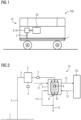
- Figure 1 shows a schematic representation of a rail vehicle 100 with a device 10, which is designed to operate a fuel cell unit 20 of the rail vehicle 100.
- the fuel cell unit 20 is designed in particular to provide drive energy for the rail vehicle 100 based on a chemical conversion process.
- the rail vehicle 100 has a main air line 1, which provides compressed air for supplying connected air mass flow consumers.
- the air mass flow consumers are, for example, a brake system, a door mechanism, a toilet system or an air suspension of the rail vehicle 100, which are operated using compressed air.
- the device 10 implements a compressed air cleaning system and represents a further air mass flow consumer that uses the compressed air from the main air line 1.
- the device 10 enables a fuel cell component 6, 16 to be flushed and cleaned and thus contributes to an efficient and cost-effective operation of the fuel cell unit 20 and the rail vehicle 100.
- Figure 2 shows a schematic view of an exemplary embodiment of the device 10, which has a supply air line 2 which is fluidly coupled to the main air line 1 of the rail vehicle 100.
- the compressed air in the main line 1 is provided and pre-cleaned, for example, by a central compressor of the rail vehicle 100.
- the compressed air taken from the main line 1 flows as a compressed air stream through the supply air line 2 in the direction of a compressed air container or compressed air storage 3 for storage.
- the compressed air storage 3 is coupled to a control unit 4, which controls an air flow through the supply air line 2.
- one or more pneumatic units 5 are coupled to the supply air line 2, which include, for example, a valve or a throttle and regulate an air flow through the supply air line 2.
- the supply air line 2 is further fluidly connected to a fuel cell component, which according to in Figure 2 illustrated embodiment is realized as a humidification unit 6.
- the humidification unit 6 has a membrane 61.
- the membrane is in Figure 2 indicated as a rectangular element with vertical lines.
- two humidity sensors 8 are arranged, which are set up to measure air humidity as an operationally relevant property of a process air.
- the process air is supplied to the fuel cell unit for the energy conversion process.
- a humidity sensor 8 is in the membrane 61 and the Another moisture sensor 8 is arranged fluidically downstream of the membrane 61.
- the membrane 61 becomes clogged, so that in terms of flow, the humidity in the process air decreases downstream of the membrane 61.
- a signal is sent to the control unit 4 of the compressed air storage 3 based on the measurement signal from the humidity sensor or sensors 8.
- a compressed air flow is then released from the compressed air storage 3 and controlled by the pneumatic unit 5 of the humidification unit 6 supplied. This means that the stored compressed air flows through and cleans the membrane 61 in a targeted manner.
- the costs for changing the humidification unit 6 can be delayed and the reliable functional life of the humidification unit 6 can be extended.
- the operating hours of the humidification unit 6 can probably be doubled before it is replaced.
- three humidification units 6 are installed for a fuel cell unit 20, so that correspondingly high maintenance costs can be saved.
- a coupling 11 is illustrated for the process air, which is provided by a compressor of the fuel cell system and supplied to the humidification unit 6.
- a coupling for the process air is also illustrated, which is based on one Passage through the humidification unit 6 of the fuel cell unit 20 is supplied.
- the coupling 13 illustrates the process air returned by the fuel cell unit 20, which is supplied to the humidification unit 6 for further humidification.
- the coupling 15 represents an output for an exhaust of the process air and/or the compressed air flow.
- the coupling 14 realizes a further output for the process air and/or the compressed air flow from the humidification unit 6 in the direction of the exhaust air duct 15.
- the device 10 thus implements a cleaning system for a fuel cell component 6, 16 and fluidly connects the main air line 1 of the rail vehicle 100 to the circuit of the fuel cell system, which includes the fuel cell unit 20.
- FIG 3 shows a schematic view of another device 10, which is not the subject of the invention.
- the device enables a cleaning process for a fuel cell component in the form of a filter unit 16.
- the filter unit 16 is arranged in a flow channel 9 and includes, for example, a multi-layer particle filter system 161, which becomes dirty and clogged over the course of the operating time.
- the device 10 has two pressure sensors 18, one of which is arranged in front of the particle filter system 161 in terms of flow and the other in terms of flow behind it.
- the pressure sensors 18 are set up to measure an air pressure as an operationally relevant variable of the process air in the filter unit 16.
- air pressure control based on measurement signals from the pressure sensor or sensors 8
- a cleaning process can also be carried out after a predetermined time interval has elapsed. This cleaning option can also be used in the exemplary embodiment with the humidification unit 6 according to Figure 2 be provided.
- the filter unit 16 used has a comparable quality and purity to a brand-new filter unit, so that significant cost savings are possible.
- the device 10 can also have an extendable compressed air division 19.
- the filter unit 16 can also be subject to a time-controlled cleaning schedule. This provides, for example, weekly interim cleaning to ensure that the particle filter system 161 can be cleaned without damage using a low air pressure of the supplied compressed air flow. After a defined time, the control unit 4 of the compressed air storage 3 initiates the cleaning process and the stored compressed air flows through the filter unit 16.
- an exhaust air duct 15 is closed off behind the filter unit 16 with a shut-off valve 17 in terms of flow.
- the exhaust air produced during the cleaning process is preferably supplied to the environment via the separate exhaust air duct 15.
- Figure 4 shows a flowchart for a method for carrying out a cleaning process of the humidification unit 6 or the filter unit 16.
- a step S1 compressed air is removed from the main line 1 and stored in the compressed air storage 3 and made available for a cleaning process.
- a step S3 for example, the expiry of a time gut is determined.
- humidity or air pressure in the process air is detected by means of the humidity sensors 8 or the pressure sensors 18.
- a step S5 it is determined whether a predetermined time interval or a predetermined time threshold value has been exceeded and/or the determined air humidity or the determined air pressure is compared with a corresponding predetermined threshold value.
- a step S7 stored compressed air is released from the compressed air storage 3 in a controlled manner and a compressed air stream is supplied to the humidification unit 6 or the filter unit 16 for cleaning when it has been determined that the predetermined time threshold has been exceeded and/or when it has been determined that the determined time threshold has been exceeded Humidity or the determined air pressure falls below the corresponding predetermined threshold value.
Landscapes
- Life Sciences & Earth Sciences (AREA)
- Engineering & Computer Science (AREA)
- Manufacturing & Machinery (AREA)
- Sustainable Development (AREA)
- Sustainable Energy (AREA)
- Chemical & Material Sciences (AREA)
- Chemical Kinetics & Catalysis (AREA)
- Electrochemistry (AREA)
- General Chemical & Material Sciences (AREA)
- Fuel Cell (AREA)
Claims (9)
- Procédé pour faire fonctionner une unité (20) de pile à combustible d'un véhicule (100) ferroviaire, dans lequel :- on se procure un courant (S1) d'air comprimé,- on se procure une variable, et- on envoie le courant d'air comprimé, par un conduit (2) d'apport d'air, dans un composant (6) d'une pile à combustible de l'unité (20) de pile à combustible, et on nettoie ainsi le composant (6) de pile à combustible, au moyen du courant d'air comprimé en fonction de la variable,dans lequel se procurer la variable comprend une détection d'un signal de mesure d'au moins un capteur (8), qui est représentatif d'une propriété, pertinente pour le fonctionnement, d'un air de processus dans le composant (6) de pile à combustible de l'unité (20) de pile à combustible, et une détermination d'une valeur de la propriété, pertinente pour le fonctionnement, de l'air de processus dans le composant (6) de pile à combustible en fonction du signal de mesure détecté et d'une égalisation de la valeur déterminée à une valeur de seuil donnée à l'avance de la propriété, pertinente pour le fonctionnement, de l'air de processus, et dans lequel on effectue l'apport du courant d'air comprimé par le conduit (2) d'apport d'air au composant (6) de pile à combustible de l'unité (20) de pile à combustible et ainsi le nettoyage du composant (6) de pile à combustible, au moyen du courant d'air comprimé, en fonction de l'égalisation de la valeur déterminée à la valeur de seuil donnée à l'avance de la propriété, pertinente pour le fonctionnement, de l'air de processus, etdans lequel le composant de pile à combustible est constitué sous la forme d'une unité (6) d'humidification pour l'humidification de l'air de processus pour l'unité (20) de pile à combustible, la propriété pertinente pour le fonctionnement est constituée sous la forme d'une humidité de l'air de processus dans l'unité (6) d'humidification et le au moins un capteur (8) sous la forme d'un capteur d'humidité pour la détection de l'humidité de l'air du processus dans l'unité (6) d'humidification, comprenant :- détection d'une humidité de l'air du processus pour l'unité (20) de pile à combustible dans l'unité (6) d'humidification,- égalisation de l'humidité de l'air détectée à une valeur de seuil donnée à l'avance de l'humidité de l'air du processus dans l'unité (6) d'humidification, et- apport du courant d'air comprimé par le conduit (2) d'apport d'air à l'unité (6) d'humidification, si l'humidité de l'air, qui a été détectée, est inférieure à la valeur de seuil donnée à l'avance de l'humidité de l'air.
- Procédé suivant la revendication 1, dans lequel se procurer la variable comprend une prescription d'une valeur de seuil de temps, et dans lequel on effectue l'apport du courant d'air comprimé par le conduit (2) d'apport d'air au composant (6) de pile à combustible de l'unité (20) de pile à combustible, et ainsi le nettoyage du composant (6) de pile à combustible au moyen du courant d'air comprimé, si la valeur de seuil de temps donnée à l'avance est dépassée.
- Procédé suivant la revendication 1, dans lequel l'unité (6) d'humidification a une membrane (61) et un capteur (8) d'humidité dans l'unité (6) d'humidification et, en technique des fluides, montée avant la membrane (61), et un autre capteur (8) d'humidité dans l'unité (6) d'humidification est monté, en technique des fluides, derrière la membrane (61) comprenant :- détection d'une première humidité de l'air de processus, en technique des fluides avant la membrane (61) de l'unité (6) d'humidification, au moyen du capteur (8) d'humidité,- détection d'une deuxième humidité de l'air de processus, en technique des fluides derrière la membrane (61) de l'unité (6) d'humidification, au moyen de l'autre capteur (8) d'humidité,- égalisation de la première et de la deuxième humidités détectées de l'air de processus, et- apport du courant d'air comprimé par le conduit (2) d'apport d'air à l'unité (6) d'humidification, en fonction de l'égalisation des première et deuxième humidités de l'air, qui ont été détectées.
- Procédé suivant l'une des revendications 1 à 3, comprenant- prescription d'une valeur (S5) de seuil de temps, et- apport du courant d'air comprimé au composant (6) de pile à combustible de l'unité (20) de pile à combustible et ainsi nettoyage du composant (6) de pile à combustible, au moyen du courant d'air comprimé, en fonction de la valeur de seuil de temps donnée à l'avance et de la valeur déterminée de la propriété, pertinente pour le fonctionnement, de l'air de processus dans le composant (6) de pile à combustible.
- Installation (10) pour faire fonctionner une unité (2) de pile à combustible d'un véhicule (100) ferroviaire, comportant :- un conduit (2) d'apport d'air pour envoyer un courant d'air comprimé, qui, en technique des fluides, peut être relié à un conduit (1) d'air principal pour la conduite d'air comprimé et pour l'alimentation de consommateurs de courant massique d'air du véhicule (100) ferroviaire, et- un composant (6) de pile à combustible pour le traitement de l'air de processus pour l'unité (20) de pile à combustible, qui est reliée, en technique des fluides, au conduit (2) d'apport d'air de manière à pouvoir introduire le courant d'air comprimé par le conduit (2) d'apport d'air dans le composant (6) de pile à combustible et effectuer ainsi un nettoyage du composant (6) de pile à combustible,- au moins un capteur (8), qui est relié au composant (6) de pile à combustible et qui est agencé pour détecter un signal de mesure, qui est représentatif d'une propriété, pertinente pour le fonctionnement, d'un air de processus dans le composant (6) de pile à combustible, dans lequel le composant de pile à combustible est constitué sous la forme d'une unité (6) d'humidification pour l'humidification de l'air de processus pour l'unité (20) de pile à combustible, et le au moins un capteur, sous la forme d'un capteur (8) d'humidité pour la détection d'une humidité de l'air de processus dans l'unité (6) d'humidification, comme propriété pertinente pour le fonctionnement,dans lequel l'installation est conformée :
pour égaliser une valeur de l'humidité détectée de l'air de processus à une valeur de seuil donnée à l'avance de la propriété, pertinente pour le fonctionnement, de l'air du processus, et pour envoyer le courant d'air comprimé par le conduit (2) d'apport d'air dans l'unité (6) d'humidification et nettoyer ainsi l'unité (6) d'humidification, au moyen du courant d'air comprimé, si la valeur de l'humidité de l'air est inférieure à la valeur de seuil donnée à l'avance. - Installation (10) suivant la revendication 5, dans laquelle l'unité (6) d'humidification a une membrane (61) et un capteur (8) d'humidité dans l'unité (6) d'humidification est montée, en technique des fluides avant la membrane (61), et un autre capteur (8) d'humidité dans l'unité (6) d'humidification est monté, en technique des fluides derrière la membrane (61).
- Installation (10) suivant la revendication 5 ou 6, comprenant :
un accumulateur (3) d'air comprimé pour recevoir et céder de l'air comprimé, qui est relié en technique des fluides au conduit (2) d'apport d'air et qui met l'air du courant d'air comprimé à disposition pour le nettoyage du composant (6) de pile à combustible. - Installation (10) suivant l'une des revendications 5 à 7, comprenant :
une unité (5) pneumatique, pour le réglage du courant d'air dans le conduit (2) d'apport d'air, dans laquelle l'unité pneumatique est montée, en technique des fluides avant le composant (6) de pile à combustible. - Véhicule (100) ferroviaire, comprenant :- un conduit (1) d'air principal pour conduire de l'air comprimé et pour alimenter des consommateurs de courant massique d'air du véhicule (100) ferroviaire,- une unité (20) de pile à combustible pour disposer d'énergie d'entraînement du véhicule (100) ferroviaire, et- une installation (10) suivant l'une des revendications 5 à 8, pour faire fonctionner l'unité (20) de pile à combustible, dans laquelle le conduit (2) d'apport d'air communique, en technique des fluides, avec le conduit (1) d'air principal et le composant (6, 16) de pile à combustible communique, en technique des fluides, avec l'unité (20) de pile à combustible.
Applications Claiming Priority (1)
| Application Number | Priority Date | Filing Date | Title |
|---|---|---|---|
| DE102019211171.8A DE102019211171A1 (de) | 2019-07-26 | 2019-07-26 | Verfahren, Vorrichtung und Schienenfahrzeug |
Publications (2)
| Publication Number | Publication Date |
|---|---|
| EP3771009A1 EP3771009A1 (fr) | 2021-01-27 |
| EP3771009B1 true EP3771009B1 (fr) | 2023-12-13 |
Family
ID=71575125
Family Applications (1)
| Application Number | Title | Priority Date | Filing Date |
|---|---|---|---|
| EP20185151.6A Active EP3771009B1 (fr) | 2019-07-26 | 2020-07-10 | Procédé et dispositif pour rincer un composant d'une pile à combustible, et véhicule ferroviaire |
Country Status (4)
| Country | Link |
|---|---|
| EP (1) | EP3771009B1 (fr) |
| CN (1) | CN112310442B (fr) |
| DE (1) | DE102019211171A1 (fr) |
| ES (1) | ES2972829T3 (fr) |
Families Citing this family (5)
| Publication number | Priority date | Publication date | Assignee | Title |
|---|---|---|---|---|
| DE102020208571A1 (de) | 2020-07-08 | 2022-01-13 | Siemens Mobility GmbH | Verfahren zum Betreiben eines Brennstoffzellensystems in einem Schienenfahrzeug |
| DE102021201474A1 (de) * | 2021-02-16 | 2022-08-18 | Knorr-Bremse Systeme für Nutzfahrzeuge GmbH | Betriebsstrategie zur effizienten Druckluftversorgung von Brennstoffzelle und Druckluftsystem |
| DE102021211032A1 (de) * | 2021-09-30 | 2023-03-30 | Siemens Mobility GmbH | Verfahren zum Betreiben eines Brennstoffzellensystems in einem Schienenfahrzeug |
| DE102022214413A1 (de) * | 2022-12-27 | 2024-06-27 | Robert Bosch Gesellschaft mit beschränkter Haftung | Zellenvorrichtung mit Partikelfilter |
| DE102024204603A1 (de) | 2024-05-17 | 2025-11-20 | Robert Bosch Gesellschaft mit beschränkter Haftung | Brennstoffzellenvorrichtung und Verfahren |
Family Cites Families (10)
| Publication number | Priority date | Publication date | Assignee | Title |
|---|---|---|---|---|
| DE10001717C1 (de) * | 2000-01-18 | 2001-04-26 | Xcellsis Gmbh | Brennstoffzellensystem |
| DE10230283A1 (de) * | 2002-07-05 | 2004-01-29 | Daimlerchrysler Ag | Verfahren und Anordnung zum Reinigen der einer Brennstoffzelle für den Betrieb zuzuführenden Gase von Bestandteilen, die für den Brennstoffzellenbetrieb ungünstig sind |
| US7670700B2 (en) * | 2003-09-05 | 2010-03-02 | Denso Corporation | Fuel cell system, related method and current measuring device for fuel cell system |
| DE102009036199A1 (de) * | 2009-08-05 | 2011-02-17 | Daimler Ag | Verfahren zum Betreiben eines Brennstoffzellensystems in einem Fahrzeug |
| DE102009043569A1 (de) * | 2009-09-30 | 2011-04-07 | Daimler Ag | Verfahren zum Betreiben eines Brennstoffzellensystems |
| EP2675008B1 (fr) * | 2012-06-15 | 2020-01-22 | Airbus Operations GmbH | Système de pile à combustible et procédé de contrôle d'un système de pile à combustible |
| FI125775B (en) * | 2014-06-30 | 2016-02-15 | Teknologian Tutkimuskeskus Vtt Oy | Method and system for preventing reverse current degeneration in fuel cells |
| FR3029359A1 (fr) * | 2014-11-27 | 2016-06-03 | Michelin & Cie | Systeme a pile a combustible |
| DE102017214966A1 (de) * | 2017-08-28 | 2019-02-28 | Audi Ag | Verfahren zum Betreiben eines Befeuchtungssystems für ein Brennstoffzellensystem sowie Kraftfahrzeug mit einem solchen |
| CN208723002U (zh) * | 2018-08-20 | 2019-04-09 | 杭州休伦科技有限公司 | 燃料电池的空气供应系统 |
-
2019
- 2019-07-26 DE DE102019211171.8A patent/DE102019211171A1/de not_active Withdrawn
-
2020
- 2020-07-10 ES ES20185151T patent/ES2972829T3/es active Active
- 2020-07-10 EP EP20185151.6A patent/EP3771009B1/fr active Active
- 2020-07-24 CN CN202010728367.0A patent/CN112310442B/zh active Active
Also Published As
| Publication number | Publication date |
|---|---|
| EP3771009A1 (fr) | 2021-01-27 |
| CN112310442B (zh) | 2024-08-09 |
| CN112310442A (zh) | 2021-02-02 |
| ES2972829T3 (es) | 2024-06-17 |
| DE102019211171A1 (de) | 2021-01-28 |
Similar Documents
| Publication | Publication Date | Title |
|---|---|---|
| EP3771009B1 (fr) | Procédé et dispositif pour rincer un composant d'une pile à combustible, et véhicule ferroviaire | |
| DE112006004076B4 (de) | Brennstoffkreis eines Brennstoffzellensystems und Verfahren zum Betreiben eines Brennstoffzellensystems | |
| DE102009036197B4 (de) | Verfahren zum Betreiben eines Brennstoffzellensystems | |
| EP2715849B1 (fr) | Dispositif de recirculation pour un système de pila à combustible | |
| EP1702842A1 (fr) | Aéronef comprenant une pile à combustible | |
| DE102014223496A1 (de) | Wasserstoffabführeinheit für Brennstoffzellensystem | |
| DE102012018102B4 (de) | Verfahren zur Luftversorgung einer Brennstoffzelle | |
| DE102012219061A1 (de) | Brennstoffzellensystem mit stabilisiertem H2-Mitteldruck | |
| WO2019154846A1 (fr) | Procédé de détection de la qualité d'air d'une pile à combustible | |
| DE102008053345B4 (de) | Brennstoffzellensystem | |
| DE102020206896A1 (de) | Verfahren zur Degradationsverminderung beim Aus- und Einschalten einer Brennstoffzelle eines Brennstoffzellensystems sowie Brennstoffzellensystem | |
| DE112008002292T5 (de) | Brennstoffzellensystem und Verfahren zum Steuern einer Reaktionsgaszuführmenge | |
| WO2014114434A1 (fr) | Procédé permettant de faire fonctionner un système de piles à combustible | |
| DE102018216263A1 (de) | Verfahren zum Betreiben einer Brennstoffzellenvorrichtung, Brennstoffzellenvorrichtung und Kraftfahrzeug mit einer solchen | |
| DE102013011373A1 (de) | Vorrichtung zum Einbringen von flüssigem Wasser in einen Gasstrom | |
| WO2013110310A1 (fr) | Dispositif pour évacuer un liquide | |
| DE102009050930A1 (de) | Diagnose zur Bestimmung eines Zufrierens oder eines Ausfalls von Ventilen/Leitungen in einer Brennstoffzellen-Ablassverteilereinheit | |
| DE102019216662A1 (de) | Verfahren zum Betreiben eines Brennstoffzellensystems, Brennstoffzellensys-tem | |
| AT523896B1 (de) | Prüfstandsystem zum Prüfen von zumindest einer Brennstoffzelle | |
| WO2024110290A2 (fr) | Procédé, dispositif de commande et programme informatique pour détecter une fuite dans un système de pile à combustible, dispositif d'analyse d'étanchéité et système de pile à combustible | |
| DE102022209498A1 (de) | Verfahren zum Betreiben eines Brennstoffzellensystems, Steuergerät | |
| EP1746678B1 (fr) | Procédé pour évacuation de l'eau et des gaz inertes dans un assemblage de piles à combustible et assemblage de piles à combustible | |
| AT524901B1 (de) | Indikator-Brennstoffzelle für eine Indikation wenigstens eines Schädigungseffekts auf einen separaten Brennstoffzellenstapel eines Brennstoffzellensystems | |
| DE102019216657A1 (de) | Verfahren zum Betreiben eines Brennstoffzellensystems, Steuergerät | |
| DE102004053237A1 (de) | Steuergerät sowie Verfahren zum Betreiben eines Brennstoffzellensystems |
Legal Events
| Date | Code | Title | Description |
|---|---|---|---|
| PUAI | Public reference made under article 153(3) epc to a published international application that has entered the european phase |
Free format text: ORIGINAL CODE: 0009012 |
|
| STAA | Information on the status of an ep patent application or granted ep patent |
Free format text: STATUS: THE APPLICATION HAS BEEN PUBLISHED |
|
| AK | Designated contracting states |
Kind code of ref document: A1 Designated state(s): AL AT BE BG CH CY CZ DE DK EE ES FI FR GB GR HR HU IE IS IT LI LT LU LV MC MK MT NL NO PL PT RO RS SE SI SK SM TR |
|
| AX | Request for extension of the european patent |
Extension state: BA ME |
|
| STAA | Information on the status of an ep patent application or granted ep patent |
Free format text: STATUS: REQUEST FOR EXAMINATION WAS MADE |
|
| 17P | Request for examination filed |
Effective date: 20210726 |
|
| RBV | Designated contracting states (corrected) |
Designated state(s): AL AT BE BG CH CY CZ DE DK EE ES FI FR GB GR HR HU IE IS IT LI LT LU LV MC MK MT NL NO PL PT RO RS SE SI SK SM TR |
|
| GRAP | Despatch of communication of intention to grant a patent |
Free format text: ORIGINAL CODE: EPIDOSNIGR1 |
|
| STAA | Information on the status of an ep patent application or granted ep patent |
Free format text: STATUS: GRANT OF PATENT IS INTENDED |
|
| RIC1 | Information provided on ipc code assigned before grant |
Ipc: H01M 8/1018 20160101ALN20230531BHEP Ipc: H01M 8/04313 20160101ALI20230531BHEP Ipc: H01M 8/0444 20160101ALI20230531BHEP Ipc: H01M 8/0438 20160101ALI20230531BHEP Ipc: H01M 8/04746 20160101ALI20230531BHEP Ipc: H01M 8/04791 20160101ALI20230531BHEP Ipc: H01M 8/0662 20160101ALI20230531BHEP Ipc: H01M 8/04119 20160101AFI20230531BHEP |
|
| INTG | Intention to grant announced |
Effective date: 20230703 |
|
| GRAS | Grant fee paid |
Free format text: ORIGINAL CODE: EPIDOSNIGR3 |
|
| GRAA | (expected) grant |
Free format text: ORIGINAL CODE: 0009210 |
|
| STAA | Information on the status of an ep patent application or granted ep patent |
Free format text: STATUS: THE PATENT HAS BEEN GRANTED |
|
| AK | Designated contracting states |
Kind code of ref document: B1 Designated state(s): AL AT BE BG CH CY CZ DE DK EE ES FI FR GB GR HR HU IE IS IT LI LT LU LV MC MK MT NL NO PL PT RO RS SE SI SK SM TR |
|
| REG | Reference to a national code |
Ref country code: GB Ref legal event code: FG4D Free format text: NOT ENGLISH |
|
| REG | Reference to a national code |
Ref country code: CH Ref legal event code: EP |
|
| REG | Reference to a national code |
Ref country code: DE Ref legal event code: R096 Ref document number: 502020006356 Country of ref document: DE |
|
| REG | Reference to a national code |
Ref country code: IE Ref legal event code: FG4D Free format text: LANGUAGE OF EP DOCUMENT: GERMAN |
|
| PG25 | Lapsed in a contracting state [announced via postgrant information from national office to epo] |
Ref country code: GR Free format text: LAPSE BECAUSE OF FAILURE TO SUBMIT A TRANSLATION OF THE DESCRIPTION OR TO PAY THE FEE WITHIN THE PRESCRIBED TIME-LIMIT Effective date: 20240314 |
|
| REG | Reference to a national code |
Ref country code: LT Ref legal event code: MG9D |
|
| PG25 | Lapsed in a contracting state [announced via postgrant information from national office to epo] |
Ref country code: LT Free format text: LAPSE BECAUSE OF FAILURE TO SUBMIT A TRANSLATION OF THE DESCRIPTION OR TO PAY THE FEE WITHIN THE PRESCRIBED TIME-LIMIT Effective date: 20231213 |
|
| REG | Reference to a national code |
Ref country code: NL Ref legal event code: MP Effective date: 20231213 |
|
| PG25 | Lapsed in a contracting state [announced via postgrant information from national office to epo] |
Ref country code: LT Free format text: LAPSE BECAUSE OF FAILURE TO SUBMIT A TRANSLATION OF THE DESCRIPTION OR TO PAY THE FEE WITHIN THE PRESCRIBED TIME-LIMIT Effective date: 20231213 Ref country code: GR Free format text: LAPSE BECAUSE OF FAILURE TO SUBMIT A TRANSLATION OF THE DESCRIPTION OR TO PAY THE FEE WITHIN THE PRESCRIBED TIME-LIMIT Effective date: 20240314 Ref country code: BG Free format text: LAPSE BECAUSE OF FAILURE TO SUBMIT A TRANSLATION OF THE DESCRIPTION OR TO PAY THE FEE WITHIN THE PRESCRIBED TIME-LIMIT Effective date: 20240313 |
|
| PG25 | Lapsed in a contracting state [announced via postgrant information from national office to epo] |
Ref country code: NL Free format text: LAPSE BECAUSE OF FAILURE TO SUBMIT A TRANSLATION OF THE DESCRIPTION OR TO PAY THE FEE WITHIN THE PRESCRIBED TIME-LIMIT Effective date: 20231213 |
|
| PG25 | Lapsed in a contracting state [announced via postgrant information from national office to epo] |
Ref country code: SE Free format text: LAPSE BECAUSE OF FAILURE TO SUBMIT A TRANSLATION OF THE DESCRIPTION OR TO PAY THE FEE WITHIN THE PRESCRIBED TIME-LIMIT Effective date: 20231213 Ref country code: RS Free format text: LAPSE BECAUSE OF FAILURE TO SUBMIT A TRANSLATION OF THE DESCRIPTION OR TO PAY THE FEE WITHIN THE PRESCRIBED TIME-LIMIT Effective date: 20231213 Ref country code: NO Free format text: LAPSE BECAUSE OF FAILURE TO SUBMIT A TRANSLATION OF THE DESCRIPTION OR TO PAY THE FEE WITHIN THE PRESCRIBED TIME-LIMIT Effective date: 20240313 Ref country code: NL Free format text: LAPSE BECAUSE OF FAILURE TO SUBMIT A TRANSLATION OF THE DESCRIPTION OR TO PAY THE FEE WITHIN THE PRESCRIBED TIME-LIMIT Effective date: 20231213 Ref country code: LV Free format text: LAPSE BECAUSE OF FAILURE TO SUBMIT A TRANSLATION OF THE DESCRIPTION OR TO PAY THE FEE WITHIN THE PRESCRIBED TIME-LIMIT Effective date: 20231213 Ref country code: HR Free format text: LAPSE BECAUSE OF FAILURE TO SUBMIT A TRANSLATION OF THE DESCRIPTION OR TO PAY THE FEE WITHIN THE PRESCRIBED TIME-LIMIT Effective date: 20231213 |
|
| REG | Reference to a national code |
Ref country code: ES Ref legal event code: FG2A Ref document number: 2972829 Country of ref document: ES Kind code of ref document: T3 Effective date: 20240617 |
|
| PG25 | Lapsed in a contracting state [announced via postgrant information from national office to epo] |
Ref country code: IS Free format text: LAPSE BECAUSE OF FAILURE TO SUBMIT A TRANSLATION OF THE DESCRIPTION OR TO PAY THE FEE WITHIN THE PRESCRIBED TIME-LIMIT Effective date: 20240413 |
|
| PG25 | Lapsed in a contracting state [announced via postgrant information from national office to epo] |
Ref country code: CZ Free format text: LAPSE BECAUSE OF FAILURE TO SUBMIT A TRANSLATION OF THE DESCRIPTION OR TO PAY THE FEE WITHIN THE PRESCRIBED TIME-LIMIT Effective date: 20231213 |
|
| PG25 | Lapsed in a contracting state [announced via postgrant information from national office to epo] |
Ref country code: SK Free format text: LAPSE BECAUSE OF FAILURE TO SUBMIT A TRANSLATION OF THE DESCRIPTION OR TO PAY THE FEE WITHIN THE PRESCRIBED TIME-LIMIT Effective date: 20231213 |
|
| PG25 | Lapsed in a contracting state [announced via postgrant information from national office to epo] |
Ref country code: SM Free format text: LAPSE BECAUSE OF FAILURE TO SUBMIT A TRANSLATION OF THE DESCRIPTION OR TO PAY THE FEE WITHIN THE PRESCRIBED TIME-LIMIT Effective date: 20231213 Ref country code: SK Free format text: LAPSE BECAUSE OF FAILURE TO SUBMIT A TRANSLATION OF THE DESCRIPTION OR TO PAY THE FEE WITHIN THE PRESCRIBED TIME-LIMIT Effective date: 20231213 Ref country code: RO Free format text: LAPSE BECAUSE OF FAILURE TO SUBMIT A TRANSLATION OF THE DESCRIPTION OR TO PAY THE FEE WITHIN THE PRESCRIBED TIME-LIMIT Effective date: 20231213 Ref country code: IT Free format text: LAPSE BECAUSE OF FAILURE TO SUBMIT A TRANSLATION OF THE DESCRIPTION OR TO PAY THE FEE WITHIN THE PRESCRIBED TIME-LIMIT Effective date: 20231213 Ref country code: IS Free format text: LAPSE BECAUSE OF FAILURE TO SUBMIT A TRANSLATION OF THE DESCRIPTION OR TO PAY THE FEE WITHIN THE PRESCRIBED TIME-LIMIT Effective date: 20240413 Ref country code: EE Free format text: LAPSE BECAUSE OF FAILURE TO SUBMIT A TRANSLATION OF THE DESCRIPTION OR TO PAY THE FEE WITHIN THE PRESCRIBED TIME-LIMIT Effective date: 20231213 Ref country code: CZ Free format text: LAPSE BECAUSE OF FAILURE TO SUBMIT A TRANSLATION OF THE DESCRIPTION OR TO PAY THE FEE WITHIN THE PRESCRIBED TIME-LIMIT Effective date: 20231213 |
|
| PG25 | Lapsed in a contracting state [announced via postgrant information from national office to epo] |
Ref country code: PL Free format text: LAPSE BECAUSE OF FAILURE TO SUBMIT A TRANSLATION OF THE DESCRIPTION OR TO PAY THE FEE WITHIN THE PRESCRIBED TIME-LIMIT Effective date: 20231213 Ref country code: PT Free format text: LAPSE BECAUSE OF FAILURE TO SUBMIT A TRANSLATION OF THE DESCRIPTION OR TO PAY THE FEE WITHIN THE PRESCRIBED TIME-LIMIT Effective date: 20240415 |
|
| PG25 | Lapsed in a contracting state [announced via postgrant information from national office to epo] |
Ref country code: PT Free format text: LAPSE BECAUSE OF FAILURE TO SUBMIT A TRANSLATION OF THE DESCRIPTION OR TO PAY THE FEE WITHIN THE PRESCRIBED TIME-LIMIT Effective date: 20240415 Ref country code: PL Free format text: LAPSE BECAUSE OF FAILURE TO SUBMIT A TRANSLATION OF THE DESCRIPTION OR TO PAY THE FEE WITHIN THE PRESCRIBED TIME-LIMIT Effective date: 20231213 |
|
| REG | Reference to a national code |
Ref country code: DE Ref legal event code: R097 Ref document number: 502020006356 Country of ref document: DE |
|
| PG25 | Lapsed in a contracting state [announced via postgrant information from national office to epo] |
Ref country code: DK Free format text: LAPSE BECAUSE OF FAILURE TO SUBMIT A TRANSLATION OF THE DESCRIPTION OR TO PAY THE FEE WITHIN THE PRESCRIBED TIME-LIMIT Effective date: 20231213 |
|
| PLBE | No opposition filed within time limit |
Free format text: ORIGINAL CODE: 0009261 |
|
| STAA | Information on the status of an ep patent application or granted ep patent |
Free format text: STATUS: NO OPPOSITION FILED WITHIN TIME LIMIT |
|
| PG25 | Lapsed in a contracting state [announced via postgrant information from national office to epo] |
Ref country code: SI Free format text: LAPSE BECAUSE OF FAILURE TO SUBMIT A TRANSLATION OF THE DESCRIPTION OR TO PAY THE FEE WITHIN THE PRESCRIBED TIME-LIMIT Effective date: 20231213 |
|
| PG25 | Lapsed in a contracting state [announced via postgrant information from national office to epo] |
Ref country code: SI Free format text: LAPSE BECAUSE OF FAILURE TO SUBMIT A TRANSLATION OF THE DESCRIPTION OR TO PAY THE FEE WITHIN THE PRESCRIBED TIME-LIMIT Effective date: 20231213 Ref country code: DK Free format text: LAPSE BECAUSE OF FAILURE TO SUBMIT A TRANSLATION OF THE DESCRIPTION OR TO PAY THE FEE WITHIN THE PRESCRIBED TIME-LIMIT Effective date: 20231213 |
|
| 26N | No opposition filed |
Effective date: 20240916 |
|
| PG25 | Lapsed in a contracting state [announced via postgrant information from national office to epo] |
Ref country code: MC Free format text: LAPSE BECAUSE OF FAILURE TO SUBMIT A TRANSLATION OF THE DESCRIPTION OR TO PAY THE FEE WITHIN THE PRESCRIBED TIME-LIMIT Effective date: 20231213 |
|
| REG | Reference to a national code |
Ref country code: CH Ref legal event code: PL |
|
| PG25 | Lapsed in a contracting state [announced via postgrant information from national office to epo] |
Ref country code: LU Free format text: LAPSE BECAUSE OF NON-PAYMENT OF DUE FEES Effective date: 20240710 |
|
| PG25 | Lapsed in a contracting state [announced via postgrant information from national office to epo] |
Ref country code: LU Free format text: LAPSE BECAUSE OF NON-PAYMENT OF DUE FEES Effective date: 20240710 |
|
| PG25 | Lapsed in a contracting state [announced via postgrant information from national office to epo] |
Ref country code: BE Free format text: LAPSE BECAUSE OF NON-PAYMENT OF DUE FEES Effective date: 20240731 Ref country code: CH Free format text: LAPSE BECAUSE OF NON-PAYMENT OF DUE FEES Effective date: 20240731 |
|
| REG | Reference to a national code |
Ref country code: BE Ref legal event code: MM Effective date: 20240731 |
|
| PG25 | Lapsed in a contracting state [announced via postgrant information from national office to epo] |
Ref country code: IE Free format text: LAPSE BECAUSE OF NON-PAYMENT OF DUE FEES Effective date: 20240710 |
|
| REG | Reference to a national code |
Ref country code: DE Ref legal event code: R081 Ref document number: 502020006356 Country of ref document: DE Owner name: SIEMENS MOBILITY GMBH, DE Free format text: FORMER OWNER: SIEMENS MOBILITY GMBH, 81739 MUENCHEN, DE |
|
| PG25 | Lapsed in a contracting state [announced via postgrant information from national office to epo] |
Ref country code: FI Free format text: LAPSE BECAUSE OF FAILURE TO SUBMIT A TRANSLATION OF THE DESCRIPTION OR TO PAY THE FEE WITHIN THE PRESCRIBED TIME-LIMIT Effective date: 20231213 |
|
| PGFP | Annual fee paid to national office [announced via postgrant information from national office to epo] |
Ref country code: DE Payment date: 20250919 Year of fee payment: 6 |
|
| PGFP | Annual fee paid to national office [announced via postgrant information from national office to epo] |
Ref country code: GB Payment date: 20250811 Year of fee payment: 6 |
|
| PGFP | Annual fee paid to national office [announced via postgrant information from national office to epo] |
Ref country code: AT Payment date: 20251020 Year of fee payment: 5 Ref country code: FR Payment date: 20250716 Year of fee payment: 6 |
|
| PG25 | Lapsed in a contracting state [announced via postgrant information from national office to epo] |
Ref country code: CY Free format text: LAPSE BECAUSE OF FAILURE TO SUBMIT A TRANSLATION OF THE DESCRIPTION OR TO PAY THE FEE WITHIN THE PRESCRIBED TIME-LIMIT; INVALID AB INITIO Effective date: 20200710 |
|
| PGFP | Annual fee paid to national office [announced via postgrant information from national office to epo] |
Ref country code: ES Payment date: 20251020 Year of fee payment: 6 |
|
| PG25 | Lapsed in a contracting state [announced via postgrant information from national office to epo] |
Ref country code: HU Free format text: LAPSE BECAUSE OF FAILURE TO SUBMIT A TRANSLATION OF THE DESCRIPTION OR TO PAY THE FEE WITHIN THE PRESCRIBED TIME-LIMIT; INVALID AB INITIO Effective date: 20200710 |