EP3771114A1 - Basisstation und übertragungsverfahren mit einer basisstation - Google Patents
Basisstation und übertragungsverfahren mit einer basisstation Download PDFInfo
- Publication number
- EP3771114A1 EP3771114A1 EP19770927.2A EP19770927A EP3771114A1 EP 3771114 A1 EP3771114 A1 EP 3771114A1 EP 19770927 A EP19770927 A EP 19770927A EP 3771114 A1 EP3771114 A1 EP 3771114A1
- Authority
- EP
- European Patent Office
- Prior art keywords
- transmission
- user terminals
- base station
- data signals
- section
- Prior art date
- Legal status (The legal status is an assumption and is not a legal conclusion. Google has not performed a legal analysis and makes no representation as to the accuracy of the status listed.)
- Pending
Links
Images




Classifications
-
- H—ELECTRICITY
- H04—ELECTRIC COMMUNICATION TECHNIQUE
- H04B—TRANSMISSION
- H04B7/00—Radio transmission systems, i.e. using radiation field
- H04B7/02—Diversity systems; Multi-antenna system, i.e. transmission or reception using multiple antennas
- H04B7/04—Diversity systems; Multi-antenna system, i.e. transmission or reception using multiple antennas using two or more spaced independent antennas
- H04B7/06—Diversity systems; Multi-antenna system, i.e. transmission or reception using multiple antennas using two or more spaced independent antennas at the transmitting station
- H04B7/0613—Diversity systems; Multi-antenna system, i.e. transmission or reception using multiple antennas using two or more spaced independent antennas at the transmitting station using simultaneous transmission
- H04B7/0615—Diversity systems; Multi-antenna system, i.e. transmission or reception using multiple antennas using two or more spaced independent antennas at the transmitting station using simultaneous transmission of weighted versions of same signal
- H04B7/0617—Diversity systems; Multi-antenna system, i.e. transmission or reception using multiple antennas using two or more spaced independent antennas at the transmitting station using simultaneous transmission of weighted versions of same signal for beam forming
-
- H—ELECTRICITY
- H04—ELECTRIC COMMUNICATION TECHNIQUE
- H04B—TRANSMISSION
- H04B7/00—Radio transmission systems, i.e. using radiation field
- H04B7/02—Diversity systems; Multi-antenna system, i.e. transmission or reception using multiple antennas
- H04B7/04—Diversity systems; Multi-antenna system, i.e. transmission or reception using multiple antennas using two or more spaced independent antennas
- H04B7/0413—MIMO systems
- H04B7/0452—Multi-user MIMO systems
-
- H—ELECTRICITY
- H04—ELECTRIC COMMUNICATION TECHNIQUE
- H04B—TRANSMISSION
- H04B7/00—Radio transmission systems, i.e. using radiation field
- H04B7/02—Diversity systems; Multi-antenna system, i.e. transmission or reception using multiple antennas
- H04B7/04—Diversity systems; Multi-antenna system, i.e. transmission or reception using multiple antennas using two or more spaced independent antennas
- H04B7/06—Diversity systems; Multi-antenna system, i.e. transmission or reception using multiple antennas using two or more spaced independent antennas at the transmitting station
-
- H—ELECTRICITY
- H04—ELECTRIC COMMUNICATION TECHNIQUE
- H04B—TRANSMISSION
- H04B7/00—Radio transmission systems, i.e. using radiation field
- H04B7/02—Diversity systems; Multi-antenna system, i.e. transmission or reception using multiple antennas
- H04B7/04—Diversity systems; Multi-antenna system, i.e. transmission or reception using multiple antennas using two or more spaced independent antennas
- H04B7/06—Diversity systems; Multi-antenna system, i.e. transmission or reception using multiple antennas using two or more spaced independent antennas at the transmitting station
- H04B7/0613—Diversity systems; Multi-antenna system, i.e. transmission or reception using multiple antennas using two or more spaced independent antennas at the transmitting station using simultaneous transmission
- H04B7/0615—Diversity systems; Multi-antenna system, i.e. transmission or reception using multiple antennas using two or more spaced independent antennas at the transmitting station using simultaneous transmission of weighted versions of same signal
- H04B7/0619—Diversity systems; Multi-antenna system, i.e. transmission or reception using multiple antennas using two or more spaced independent antennas at the transmitting station using simultaneous transmission of weighted versions of same signal using feedback from receiving side
- H04B7/0621—Feedback content
- H04B7/063—Parameters other than those covered in groups H04B7/0623 - H04B7/0634, e.g. channel matrix rank or transmit mode selection
-
- H—ELECTRICITY
- H04—ELECTRIC COMMUNICATION TECHNIQUE
- H04W—WIRELESS COMMUNICATION NETWORKS
- H04W16/00—Network planning, e.g. coverage or traffic planning tools; Network deployment, e.g. resource partitioning or cells structures
- H04W16/24—Cell structures
- H04W16/28—Cell structures using beam steering
-
- H—ELECTRICITY
- H04—ELECTRIC COMMUNICATION TECHNIQUE
- H04W—WIRELESS COMMUNICATION NETWORKS
- H04W4/00—Services specially adapted for wireless communication networks; Facilities therefor
- H04W4/06—Selective distribution of broadcast services, e.g. multimedia broadcast multicast service [MBMS]; Services to user groups; One-way selective calling services
Definitions
- the present disclosure relates to a base station and a transmission method by the base station.
- LTE Long Term Evolution
- UMTS Universal Mobile Telecommunication System
- Future systems of LTE have also been studied for achieving a broader bandwidth and a higher speed based on LTE.
- Examples of future systems of LTE include the systems called LTE-Advanced (LTE-A), Future Radio Access (FRA), 5th generation mobile communication system (5G), 5G plus 5G+), New Radio Access Technology (New-RAT), and the like (Non-Patent Literature (hereinafter referred to as "NPL”) 1).
- Massive MIMO Massive Multiple Input Multiple Output
- a high frequency band for example, 4 GHz or higher
- Massive MIMO allows higher-speed radio communication by the effect of multiplexing and/or the like.
- Massive MIMO also allows advanced beamforming by controlling a large number of antenna elements, resulting in reduction in interference and also resulting in effects such as effective use of radio resources and/or the like.
- One object of one aspect of the present disclosure is therefore to provide a base station which improves the data transmission efficiency in the case where identical data signals are transmitted to a plurality of user terminals, and a transmission method by the base station in which the data transmission efficiency is improved.
- Abase station includes: a reception section that receives a transmission request for a data signal; a transmission section that transmits the data signal in response to reception of the transmission request using beamforming; and a control section that, when detecting a plurality of the transmission requests for a plurality of the data signals identical in content from a plurality of user terminals, applies beamforming to the data signals to be transmitted to the plurality of user terminals, the beamforming being for covering the plurality of user terminals by at least one transmission beam.
- the data transmission efficiency in the case where identical data signals are transmitted to a plurality of user terminals can be improved.
- references signs such as those in “user terminal 200a” and “user terminal 200b” may be used to describe elements of the same kind while distinguishing them from each other, and common numbers of the reference signs such as that in "user terminal(s) 200" may be used to describe the elements of the same kind without distinguishing them from each other.
- FIG. 1 illustrates an example of a configuration of radio communication system 1 according to the present embodiment.
- Radio communication system 1 illustrated in FIG. 1 includes base station (also referred to as “radio base station” or “gNB”) 100, and user terminals (also referred to as “radio terminals” or “User Equipments (UEs)”) 200a, 200b, 200c, and 200d.
- base station also referred to as “radio base station” or “gNB”
- user terminals also referred to as “radio terminals” or “User Equipments (UEs)” 200a, 200b, 200c, and 200d.
- UEs User Equipments
- the number of user terminals 200 illustrated in FIG. 1 is an example, and the number of user terminals 200 included in radio communication system 1 may be any number as long as it is equal to or greater than 2.
- Base station 100 includes a large number of antenna elements as in Massive MIMO, for example. With this configuration, base station 100 can perform advanced beamforming, so as to utilize radio resources effectively. Base station 100 also can secure broadband radio resources by utilizing a high-frequency band (e.g., several GHz to tens of GHz) for a radio signal. Additionally, since the size of each of the antenna elements is inversely proportional to the wavelength of the radio signal, the higher the utilized frequency band is, the smaller the size of an antenna including the same number of antenna elements can be made. In other words, a larger number of antenna elements can be housed in the antenna of the same size in the case of utilizing the high-frequency band. Note that, although the high-frequency band suffers from a comparatively larger propagation loss and, therefore, the received signal strength at user terminal 200 may decrease, it is possible to compensate for such a decrease by performing advanced beamforming.
- a high-frequency band e.g., several GHz to tens of GHz
- a traditional base station transmits identical data signals individually to user terminals in a case of transmitting the identical data signals, such as in a case of live distribution of a concert or a sport. Therefore, the radio resources are occupied between the base station and each of the user terminals individually, so that the data transmission efficiency decreases.
- base station 100 transmits the identical data signals by broadcast beams in the case of transmitting the identical data signals to a plurality of user terminals 200 in the present embodiment as illustrated in FIG. 1 . This improves the data transmission efficiency in the case of transmitting the identical data signals. Detailed descriptions will be given below.
- FIG. 2 is a block diagram illustrating an exemplary configuration of base station 100 according to the present embodiment.
- Base station 100 includes coding section 101, modulation section 102, estimation section 103, selection section 104, transmission control section 105, radio transmission section 106, antenna 107, and radio reception section 108.
- OFDM Orthogonal Frequency Division Multiplexing
- IFFT Inverse Fast Fourier Transform
- CP Cyclic Prefix
- Coding section 101 encodes a data signal input to coding section 101, and outputs the encoded data signal to modulation section 102.
- Modulation section 102 modulates the data signal input from coding section 101, and outputs the modulated data signal to transmission control section 105.
- Reference signals transmitted from user terminals 200 and received by antenna 107 (antenna elements) of base station 100 are input to estimation section 103.
- Estimation section 103 estimates channels between user terminals 200 and base station 100 using the reference signals (uplink signals), and outputs an estimation result to selection section 104.
- Time Division Duplex (TDD) transmission system is used in radio communication system 1 in the present embodiment.
- estimation section 103 estimates the channels of downlink signals from base station 100 to user terminals 200 using the reference signals transmitted from user terminals 200 based on the channel reciprocity.
- Estimation section 103 may also estimate the positions of user terminals 200 based on the reference signals.
- the positions of user terminals 200 may be used for determining the orientations of directivity of the transmission beams from base station 100 to user terminals 200, the shapes of the transmission beams, and/or the like.
- Selection section 104 selects channels for use in signal transmission based on the estimation result input from estimation section 103. Selection section 104 outputs selection information indicating the selected channels to transmission control section 105. Selection section 104 also selects, based on transmission requests received from user terminals 200 for the data signals, those user terminals 200 which are to be a target for data-signal transmission. Selection section 104 may select two or more user terminals 200 as targets for transmission of data signals identical in content (hereinafter, also referred to as "identical-content data signals”) from among a plurality of user terminals 200 when detecting reception of a plurality of transmission requests for the identical-content data signals from a plurality of user terminals 200.
- identical-content data signals identical in content
- Transmission control section 105 performs transmission control for transmitting the data signal input from modulation section 102.
- This data signal is a data signal addressed to user terminals 200 selected by selection section 104, for example.
- Transmission control section 105 then performs beamforming or precoding on the data signal using a plurality of antenna elements, for example.
- transmission control section 105 may generate a beamforming weight or a precoding matrix using the estimation result input from estimation section 103.
- transmission control section 105 may perform transmission power control on the data signal for user terminals 200 using the estimation result.
- Antenna 107 includes one or more antenna elements.
- Radio transmission section 106 performs radio transmission processing such as D/A conversion, frequency conversion, amplification, and/or the like on the data signal (baseband signal) input from transmission control section 105, so as to generate a radio signal. Radio transmission section 106 transmits the generated radio signal via the antenna elements (antenna 107) indicated in the transmission control information input from transmission control section 105.
- Radio reception section 108 performs radio reception processing such as A/D conversion, frequency conversion, and/or the like on radio signals received from user terminals 200 via antenna 107 (antenna elements). Radio reception section 108 outputs the reference signals included in reception signals subjected to the radio reception processing to estimation section 103.
- FIG. 3 is a block diagram illustrating an example of a configuration of user terminal 200 according to the present embodiment.
- User terminal 200 includes radio transmission section 201, antenna 202, radio reception section 203, demodulation section 204, and decoding section 205. Note that, illustration of component sections of user terminal 200 for receiving the OFDM signal (e.g., CP removal section and FFT processing section) and/or the like is omitted in FIG. 3 .
- OFDM signal e.g., CP removal section and FFT processing section
- Radio transmission section 201 performs radio transmission processing such as D/A conversion, frequency conversion, amplification, and/or the like on a reference signal and data signal input to radio transmission section 201, so as to generate a radio signal, and radio transmission section 201 transmits the generated radio signal via antenna 202.
- the data signal may include a transmission request.
- Antenna 202 includes one or more antenna elements.
- Radio reception section 203 performs radio reception processing such as A/D conversion, frequency conversion, and/or the like on a radio signal received from base station 100 via antenna 202, and outputs the reception signal subjected to the radio reception processing to demodulation section 204.
- Demodulation section 204 demodulates the reception signal input from radio reception section 203, and outputs the demodulated signal to decoding section 205.
- Decoding section 205 decodes the signal input from demodulation section 204, and outputs the data signal. With this configuration, user terminal 200 can receive the data signal corresponding to the transmission request transmitted to base station 100.
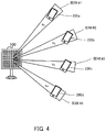
- FIG. 4 A description will be given with reference to FIG. 4 of a method for transmitting data signals different from one another to user terminals 200 before describing a method for transmitting identical data signals by broadcast to user terminals 200.
- FIG. 4 illustrates an example in which base station 100 transmits data signals s 1 , s 2 , s 3 , and s 4 to user terminals 200a, 200b, 200c, and 200d, respectively.
- transmission control section 105 performs the following processing. That is, transmission control section 105 transmits data signal s 1 by beam #1 whose directivity is directed to user terminal 200a. Transmission control section 105 transmits data signal s 2 by beam #2 whose directivity is directed to user terminal 200b. Transmission control section 105 transmits data signal s 3 by beam #3 whose directivity is directed to user terminal 200c. Transmission control section 105 transmits data signal s 4 by beam #4 whose directivity is directed to user terminal 200d.
- Transmission control section 105 forms beams #1 to #4 illustrated in FIG. 4 based on following Expression 1, for example. h 11 h 12 h 13 h 14 h 21 h 22 h 23 h 24 h 31 h 32 h 33 h 34 h 41 h 42 h 43 h 44 P s 1 s 2 s 3 s 4
- equivalent channel matrix hij including beamforming of Expression 1 is a 4 ⁇ 4 matrix. That is, "i" and "j" denote an integer of 1 to 4.
- Transmission control section 105 may generate matrix hij of Expression 1 using the estimation results on the channels and positions related to user terminals 200a to 200d.
- Precoding matrix P of Expression 1 may be a 4 ⁇ 4 matrix for mutually orthogonalizing beams #1 to #4.
- User terminal 200a may extract data signal s 1 from received beam #1.
- User terminal 200b may extract data signal s 2 from received beam #2.
- User terminal 200c may extract data signal s 3 from received beam #3.
- User terminal 200d may extract data signal s 4 from received beam #4.
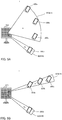
- Beam transmission method 1 for identical data signals will be described with reference to FIG. 5A .
- Beam transmission method 1 for the identical data signals will be described in relation to a method for transmitting identical-content data signals by a single beam to a plurality of user terminals 200 whose transmission requests are the same (i.e., user terminals 200 requesting transmission of the identical-content data).
- Transmission control section 105 of base station 100 performs the following processing when transmitting identical data signals s to a plurality of user terminals 200a, 200b, and 200c whose transmission requests are the same, while transmitting data signal s 4 to user terminal 200d whose transmission request is different. That is, transmission control section 105 transmits data signals s by beam #1 whose directivity is directed to cover a plurality of user terminals 200a, 200b, and 200c whose transmission requests are the same as illustrated in FIG. 5A . Transmission control section 105 transmits data signal s 4 by beam #2 whose directivity is directed to user terminal 200d. In other words, transmission control section 105 transmits data signals s by single broadcast beam #1 to a plurality of user terminals 200a, 200b, and 200c whose transmission requests are the same.
- Transmission control section 105 forms beams #1 and #2 illustrated in FIG. 5A based on following Expression 2, for example. h 11 h 12 h 21 h 22 h 31 h 32 h 41 h 42 P s s 4
- equivalent channel matrix hij including beamforming as illustrated in Expression 2 is a 4 ⁇ 2 matrix. That is, "i" and "j" denote an integer of 1 or 2.
- Transmission control section 105 may generate matrix hij of Expression 2 using the estimation results on the channels and positions related to user terminals 200a to 200d.
- Precoding matrix P of Expression 2 may be a 4 ⁇ 2 matrix for mutually orthogonalizing beams #1 and #2.
- User terminals 200a, 200b, and 200c may extract data signal s from received beam #1.
- User terminal 200d may extract data signal s 4 from received beam #2.
- base station 100 applies beamforming to cover together a plurality of user terminals 200 whose transmission requests are the same by a single transmission beam in beam transmission method 1 for the identical data signals
- the beam width does not necessarily become gradually broader as illustrated in FIG. 5A .
- transmission control section 105 makes narrower the shape of the single broadcast beam such that the single broadcast beam can reach farther when a plurality of user terminals 200 are located in a line along the direction away from base station 100 as illustrated in FIG. 5B .
- the base station would perform the following processing if data signals s are transmitted by the method illustrated in FIG. 4 to a plurality of user terminals 200a, 200b, and 200c whose transmission requests are the same. That is, the base station transmits data signals s by beams #1, #2, and #3 respectively to a plurality of user terminals 200a, 200b, and 200c whose transmission requests are the same.
- beam transmission method 1 for the identical data signals data signals s are transmitted by a single beam #1 to a plurality of user terminals 200a, 200b, and 200c whose transmission requests are the same as illustrated in FIGS. 5A and 5B . Therefore, the ratio of occupied radio resources decreases according to beam transmission method 1 for the identical data signals, so that the data transmission efficiency in the case of transmitting the identical data signals to a plurality of user terminals 200 improves.
- beam transmission method 1 for the identical data signals it is possible according to beam transmission method 1 for the identical data signals to reduce the number of antenna elements (beams) to be orthogonalized, so that base station 100 can transmit the identical data signals to a plurality of user terminals 200 with less energy.
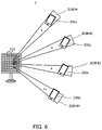
- Beam transmission method 2 for identical data signals will be described with reference to FIG. 6 .
- Beam transmission method 2 for the identical data signals will be described in relation to a method in which base station 100 transmits beams of identical-content data signals respectively to a plurality of user terminals 200 whose transmission requests are the same.
- Transmission control section 105 of base station 100 performs the following processing when transmitting identical transmission signals s to user terminals 200a, 200b, and 200c whose transmission requests are the same, while transmitting data signal s 4 to user terminal 200d whose transmission request is different. That is, transmission control section 105 transmits data signal s by beam #1 whose directivity is directed to user terminal 200a as illustrated in FIG. 6 . Transmission control section 105 transmits data signal s by beam #2 whose directivity is directed to user terminal 200b. Transmission control section 105 transmits data signal s by beam #3 whose directivity is directed to user terminal 200c. Transmission control section 105 transmits data signal s 4 by beam #4 whose directivity is directed to user terminal 200d. In other words, transmission control section 105 transmits data signals s by individual beams #1, #2, and #3 respectively to a plurality of user terminals 200a, 200b, and 200c whose transmission requests are the same.
- Transmission control section 105 forms identical beams #1, #2, #3, and #4 illustrated in FIG. 6 based on following Expression 3, for example. h 11 h 12 h 13 h 14 h 21 h 22 h 23 h 24 h 31 h 32 h 33 h 34 h 41 h 42 h 43 h 44 P s s 4
- equivalent channel matrix hij including beamforming of Expression 3 is a 4 ⁇ 4 matrix. That is, "i” and "j" denote an integer of 1 to 4.
- Transmission control section 105 may generate matrix hij of Expression 3 using the estimation results on the channels and positions related to user terminals 200a to 200d.
- Precoding matrix P of Expression 3 may be a 4 ⁇ 4 matrix for mutually orthogonalizing data signals s and transmission signal s 4 .
- User terminals 200a, 200b, and 200c may extract data signals s from received beams #1, #2, and #3, respectively.
- User terminal 200d may extract data signal s 4 from received beam #4.
- base station 100 applies beamforming for covering individually a plurality of user terminals 200 whose transmission requests are the same by a plurality of beams in beam transmission method 2 for the identical data signals
- the base station would perform the following processing if data signals s are transmitted by the method illustrated in FIG. 4 respectively to a plurality of user terminals 200a, 200b, and 200c whose transmission requests are the same while data signal s 4 is transmitted to user terminal 200d whose transmission request is different. That is, the base station orthogonalizes four data signals of data signal s transmitted to user terminal 200a, data signal s transmitted to user terminal 200b, data signal s transmitted to user terminal 200c, and data signal s 4 transmitted to user terminal 200d.
- two data signals of data signal s and data signal s 4 are orthogonalized as described above according to beam transmission method 2 for the identical data signals. Therefore, user terminals 200 whose transmission request are the same can receive data signals s by a plurality of different beams, so that a diversity gain can be obtained according to beam transmission method 2 for the identical data signals.
- base station 100 transmits data signal s 4 by single beam #4 to user terminal 200d whose transmission request is different, base station 100 may also transmit data signal s 4 by a plurality of beams to user terminal 200d.
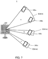
- Beam transmission method 3 for identical data signals will be described with reference to FIG. 7 .
- Beam transmission method 3 for the identical data signals will be described in relation to a method in which base station 100 applies beam transmission methods 1 and 2 for the identical data signals described above based on the positional information on user terminals 200.
- Transmission control section 105 of base station 100 performs the following processing when transmitting identical data signals s to a plurality of user terminals 200a, 200b, and 200d whose transmission requests are the same, while transmitting data signal s4 to user terminal 200c whose transmission request is different. That is, transmission control section 105 transmits data signals s to user terminals 200a and 200b by beam #1 whose directivity is directed to cover a plurality of user terminals 200a and 200b as illustrated in FIG. 7 ; user terminals 200a and 200b are, of a plurality of user terminals 200a, 200b, and 200d whose transmission requests are the same, those which exist at positions covered by a single beam.
- Transmission control section 105 transmits, by beam #3 whose directivity is directed to user terminal 200d, data signal s to user terminal 200d existing at a position not covered by aforementioned single beam #1. Transmission control section 105 transmits data signal s 3 to user terminal 200c whose transmission request is different by beam #2 whose directivity is directed to user terminal 200c.
- base station 100 selects, of a plurality of user terminals 200 whose transmission requests are the same, two or more user terminals 200 to be covered together by a single beam based on the positional information on user terminals 200 in beam transmission method 3 for the identical data signals.
- Transmission control section 105 searches for user terminals 200 whose transmission requests are the same from the information on control channels or data channels (uplink signals) transmitted from user terminals 200 (S101).
- transmission control section 105 When transmission control section 105 does not detect user terminals 200 whose transmission requests are the same by the search at S101 or when the number of detected user terminals 200 whose transmission requests are the same is less than two (S102: NO), individual beams are transmitted as illustrated in the example of FIG. 4 (S103) and the present processing is ended (END).
- transmission control section 105 When transmission control section 105 detects two or more user terminals 200 whose transmission requests are the same by the search at S101 (S102: YES), transmission control section 105 searches for two or more user terminals 200 existing at positions covered together by a single beam among a plurality of detected user terminals 200 (S104).
- Transmission control section 105 performs processing of S107 when transmission control section 105 does not detect two or more user terminals 200 by the search at S104 (S105: NO).
- transmission control section 105 When transmission control section 105 detects two or more user terminals 200 by the search at S104 (S105: YES), transmission control section 105 determines to transmit identical-content data signals to these two or more user terminals 200 by a single beam (S106) and performs processing of S107.
- Transmission control section 105 determines to transmit identical-content data signals by individual beams to user terminals 200 which are not covered together by the single beam at S106 and whose transmission requests are the same (S107).
- Transmission control section 105 determines to transmit, by an individual beam, a data signal to user terminal 200 whose transmission request is different (S108).
- Transmission control section 105 performs beamforming or precoding for transmitting the beams determined at S106, S107, and S108 (S109). Transmission control section 105 then controls radio transmission section 106 for transmitting the data signals by the beams (S110) and ends the present processing (END).
- the beams are orthogonalized in the above descriptions, not all of the beams necessarily need to be orthogonalized in the present embodiment. For example, when two beams are spatially multiplexed and signal separation is available for the two beams in the present embodiment, these two beams do not have to be orthogonalized.
- base station 100 may stand by for a predetermined period or stand by until a predetermined time instead of immediately transmitting identical-content data signals, and, in a case where base station 100 further detects user terminals 200 whose transmission requests are the same during the stand-by period, those user terminals 200 may also be included as the targets for transmission of the identical-content data signals.
- the opportunities to transmit the broadcast beam increase, so that the data transmission efficiency improves.
- base station 100 when base station 100 detects reception of a plurality of transmission requests for identical-content data signals from a plurality of user terminals 200, base station 100 applies, to the data signals to be transmitted to a plurality of user terminals 200, beamforming for covering a plurality of user terminals 200 by at least one transmission beam, and transmits, by the transmission beam, the data signals to which the beamforming has been applied.
- the block diagrams used to describe the embodiments illustrate blocks on the basis of functions. These functional blocks (constituent sections) are implemented by any combination of hardware and/or software. A means for implementing the functional blocks is not particularly limited. That is, the functional blocks may be implemented by one physically and/or logically coupled apparatus. Two or more physically and/or logically separated apparatuses may be directly and/or indirectly (for example, via wires and/or wirelessly) connected, and the plurality of apparatuses may implement the functional blocks.
- base station 100, user terminal 200, and the like may function as a computer that executes processing of a radio communication method of the present disclosure.
- FIG. 9 illustrates an example of a hardware configuration of base station 100 and user terminal 200 according to an embodiment of the present disclosure.
- Base station 100 and user terminal 200 described above may be physically constituted as a computer apparatus including processor 1001, memory 1002, storage 1003, communication apparatus 1004, input apparatus 1005, output apparatus 1006, bus 1007, and the like.
- the term "apparatus” in the following description can be replaced with a circuit, a device, a unit, or the like.
- the hardware configurations of the base station and of the user terminal may include one or more of the apparatuses illustrated in the drawings or may not include a part of the apparatuses.
- processor 1001 may be implemented by one or more chips.
- the functions in the base station and user terminal are implemented by predetermined software (program) loaded into hardware, such as processor 1001, memory 1002, and the like, according to which processor 1001 performs the arithmetic and controls communication performed by communication apparatus 1004 or reading and/or writing of data in memory 1002 and storage 1003.
- predetermined software program loaded into hardware, such as processor 1001, memory 1002, and the like, according to which processor 1001 performs the arithmetic and controls communication performed by communication apparatus 1004 or reading and/or writing of data in memory 1002 and storage 1003.
- Processor 1001 operates an operating system to entirely control the computer, for example.
- Processor 1001 may be composed of a central processing unit (CPU) including an interface with peripheral apparatuses, control apparatus, arithmetic apparatus, register, and the like.
- CPU central processing unit
- coding section 101, modulation section 102, estimation section 103, selection section 104, transmission control section 105, demodulation section 204, decoding section 205, and the like described above may be implemented by processor 1001.
- a necessary table may be stored in memory 1002.
- Processor 1001 reads out a program (program code), a software module, or data from storage 1003 and/or communication apparatus 1004 to memory 1002 and executes various types of processing according to the read-out program or the like.
- the program used is a program for causing the computer to execute at least part of the operation described in the embodiments.
- at least part of the functional blocks constituting base station 100 and user terminal 200 may be implemented by a control program stored in memory 1002 and operated by processor 1001, and the other functional blocks may also be implemented in the same way. While it has been described that the various types of processing as described above are executed by one processor 1001, the various types of processing may be executed by two or more processors 1001 at the same time or in succession.
- Processor 1001 may be implemented by one or more chips. Note that the program may be transmitted from a network through a telecommunication line.
- Memory 1002 is a computer-readable recording medium and may be composed of, for example, at least one of a Read Only Memory (ROM), an Erasable Programmable ROM (EPROM), an Electrically Erasable Programmable ROM (EEPROM), and a Random Access Memory (RAM).
- ROM Read Only Memory
- EPROM Erasable Programmable ROM
- EEPROM Electrically Erasable Programmable ROM
- RAM Random Access Memory
- Memory 1002 may be called a register, a cache, a main memory (main storage apparatus), or the like.
- Memory 1002 can save a program (program code), a software module, and the like that can be executed to carry out the radio communication method according to an embodiment of the present disclosure.
- Storage 1003 is a computer-readable recording medium and may be composed of, for example, at least one of an optical disk such as a Compact Disc ROM (CD-ROM), a hard disk drive, a flexible disk, a magneto-optical disk (for example, a compact disc, a digital versatile disc, or a Blue-ray (registered trademark) disc), a smart card, a flash memory (for example, a card, a stick, or a key drive), a floppy (registered trademark) disk, and a magnetic strip.
- Storage 1003 may also be called an auxiliary storage apparatus.
- the storage medium as described above may be a database, server, or other appropriate media including memory 1002 and/or storage 1003.
- Communication apparatus 1004 is hardware (transmission and reception device) for communication between computers through a wired and/or wireless network and is also called, for example, a network device, a network controller, a network card, or a communication module.
- a network device for example, a network controller, a network card, or a communication module.
- radio transmission sections 106 and 201, antennas 107 and 202, radio reception sections 108 and 203, and the like described above may be implemented by communication apparatus 1004.
- Input apparatus 1005 is an input device (for example, a keyboard, a mouse, a microphone, a switch, a button, or a sensor) that receives input from the outside.
- Output apparatus 1006 is an output device (for example, a display, a speaker, or an LED lamp) which outputs to the outside. Note that input apparatus 1005 and output apparatus 1006 may be integrated (for example, a touch panel).
- Bus 1007 may be composed of a single bus or by buses different among the apparatuses.
- base station 100 and user terminal 200 may include hardware, such as a microprocessor, a digital signal processor (DSP), an Application Specific Integrated Circuit (ASIC), a Programmable Logic Device (PLD), and a Field Programmable Gate Array (FPGA), and the hardware may implement part or all of the functional blocks.
- DSP digital signal processor
- ASIC Application Specific Integrated Circuit
- PLD Programmable Logic Device
- FPGA Field Programmable Gate Array
- processor 1001 may be implemented by at least one of these pieces of hardware.
- the notification of information is not limited to the aspects or embodiments described in the present specification, and the information may be notified by another method.
- the notification of information may be carried out by one or a combination of physical layer signaling (for example, Downlink Control Information (DCI) and Uplink Control Information (UCI)), higher layer signaling (for example, Radio Resource Control (RRC) signaling, Medium Access Control (MAC) signaling, broadcast information (Master Information Block (MIB) and System Information Block (SIB)), and other signals.
- the RRC signaling may be called an RRC message and may be, for example, an RRC connection setup message, an RRC connection reconfiguration message, or the like.
- LTE Long Term Evolution
- LTE-A LTE-Advanced
- SUPER 3G IMT-Advanced
- 4G 5G
- Future Radio Access FAA
- W-CDMA registered trademark
- GSM registered trademark
- CDMA2000 Code Division Multiple Access 2000
- UMB Ultra Mobile Broadband
- IEEE 802.11 Wi-Fi
- IEEE 802.16 WiMAX
- IEEE 802.20 Ultra-WideBand (UWB)
- Bluetooth registered trademark
- Specific operations which are described in the specification as being performed by the base station may sometimes be performed by an upper node depending on the situation.
- Various operations performed for communication with a terminal in a network constituted by one network node or a plurality of network nodes including a base station can be obviously performed by the base station and/or a network node other than the base station (examples include, but not limited to, Mobility Management Entity (MME) or Serving Gateway (S-GW)).
- MME Mobility Management Entity
- S-GW Serving Gateway
- the information, the signals, and the like can be output from a higher layer (or a lower layer) to a lower layer (or a higher layer).
- the information or the like may be input and output through a plurality of network nodes.
- the input and output information and the like may be saved in a specific place (for example, memory) or may be managed by a management table.
- the input and output information and the like can be overwritten, updated, or additionally written.
- the output information and the like may be deleted.
- the input information and the like may be transmitted to another apparatus.
- the determination may be made based on a value expressed by one bit (0 or 1), based on a Boolean value (true or false), or based on comparison with a numerical value (for example, comparison with a predetermined value).
- the software should be broadly interpreted to mean an instruction, an instruction set, a code, a code segment, a program code, a program, a subprogram, a software module, an application, a software application, a software package, a routine, a subroutine, an object, an executable file, an execution thread, a procedure, a function, and the like.
- the software, the instruction, and the like may be transmitted and received through a transmission medium.
- a transmission medium such as a coaxial cable, an optical fiber cable, a twisted pair, and a digital subscriber line (DSL), and/or a wireless technique, such as an infrared ray, a radio wave, and a microwave
- the wired technique and/or the wireless technique is included in the definition of the transmission medium.
- the information, the signals, and the like described in the present specification may be expressed by using any of various different techniques.
- data, instructions, commands, information, signals, bits, symbols, chips, and the like that may be mentioned throughout the entire description may be expressed by one or an arbitrary combination of voltage, current, electromagnetic waves, magnetic fields, magnetic particles, optical fields, and photons.
- the channel and/or the symbol may be a signal.
- the signal may be a message.
- the component carrier (CC) may be called a carrier frequency, a cell, or the like.
- system and "network” used in the present specification can be interchangeably used.
- radio resources may be indicated by indices.
- the base station can accommodate one cell or a plurality of (for example, three) cells (also called sector).
- the entire coverage area of the base station can be divided into a plurality of smaller areas, and each of the smaller areas can provide a communication service based on a base station subsystem (for example, small base station for indoor, remote radio head (RRH)).
- a base station subsystem for example, small base station for indoor, remote radio head (RRH)
- RRH remote radio head
- the term “cell” or “sector” denotes part or all of the coverage area of the base station and/or of the base station subsystem that perform the communication service in the coverage.
- the terms “base station”, “eNB”, “cell”, and “sector” can be interchangeably used in the present specification.
- the base station may be called a fixed station, a NodeB, an eNodeB (eNB), an access point, a femto cell, a small cell, or the like.
- the user terminal may be called, by those skilled in the art, a mobile station, a subscriber station, a mobile unit, a subscriber unit, a wireless unit, a remote unit, a mobile device, a wireless device, a wireless communication device, a remote device, a mobile subscriber station, an access terminal, a mobile terminal, a wireless terminal, a remote terminal, a handset, a user agent, a mobile client, a client, or a User Equipment (UE) or by some other appropriate terms.
- UE User Equipment
- determining may encompass a wide variety of actions. For example, “determining” may be regarded as judging, calculating, computing, processing, deriving, investigating, looking up (e.g., looking up in a table, a database or another data structure), ascertaining and the like. Also, “determining” may be regarded as receiving (e.g., receiving information), transmitting (e.g., transmitting information), inputting, outputting, accessing (e.g., accessing data in a memory) and the like. Also, “determining” may be regarded as resolving, selecting, choosing, establishing and the like. That is, “determining” may be regarded as a certain type of action related to determining.
- connection and coupling as well as any modifications of the terms mean any direct or indirect connection and coupling between two or more elements, and the terms can include cases in which one or more intermediate elements exist between two “connected” or “coupled” elements.
- the coupling or the connection between elements may be physical or logical coupling or connection or may be a combination of physical and logical coupling or connection.
- two elements can be considered to be “connected” or “coupled” to each other by using one or more electrical wires, cables, and/or printed electrical connections or by using electromagnetic energy, such as electromagnetic energy with a wavelength of a radio frequency domain, a microwave domain, or an optical (both visible and invisible) domain that are non-limiting and non-inclusive examples.
- the reference signal can also be abbreviated as RS and may also be called a pilot depending on the applied standard.
- the correction RS may be called a Tracking RS TRS), a Phase Compensation RS (PC-RS), a Phase Tracking RS (PTRS), or an additional RS.
- the demodulation RS and the correction RS may be called by other corresponding names, respectively.
- the demodulation RS and the correction RS may be specified by the same name (for example, demodulation RS).
- the radio frame may be constituted by one frame or a plurality of frames in the time domain.
- the one frame or each of the plurality of frames may be called a subframe, a time unit, or the like in the time domain.
- the subframe may be further constituted by one slot or a plurality of slots in the time domain.
- the slot may be further constituted by one symbol or a plurality of symbols (Orthogonal Frequency Division Multiplexing (OFDM)) symbol, Single Carrier-Frequency Division Multiple Access (SC-FDMA) symbol, or the like) in the time domain.
- OFDM Orthogonal Frequency Division Multiplexing
- SC-FDMA Single Carrier-Frequency Division Multiple Access
- the radio frame, the subframe, the slot, and the symbol indicate time units in transmitting signals.
- the radio frame, the subframe, the slot, and the symbol may be called by other corresponding names.
- the base station creates a schedule for assigning radio resources to each mobile station (such as frequency bandwidth that can be used by each mobile station and transmission power).
- the minimum time unit of scheduling may be called a Transmission Time Interval (TTI).
- TTI Transmission Time Interval
- one subframe, a plurality of continuous subframes, or one slot may be called a TTI.
- the resource unit is a resource assignment unit in the time domain and the frequency domain, and the resource unit may include one subcarrier or a plurality of continuous subcarriers in the frequency domain.
- the resource unit may include one symbol or a plurality of symbols in the time domain, and may have a length of one slot, one subframe, or one TTI.
- One TTI and one subframe may be constituted by one resource unit or a plurality of resource units.
- the resource unit may be called a resource block (RB), a physical resource block (PRB: Physical RB), a PRB pair, an RB pair, a scheduling unit, a frequency unit, or a subband.
- the resource unit may be constituted by one RE or a plurality of REs. For example, one RE only has to be a resource smaller in unit size than the resource unit serving as a resource assignment unit (for example, one RE only has to be a minimum unit of resource), and the naming is not limited to RE.
- the structure of the radio frame is illustrative only, and the number of subframes included in the radio frame, the number of slots included in the subframe, the numbers of symbols and resource blocks included in the slot, and the number of subcarriers included in the resource block can be changed in various ways.
- notification of predetermined information is not limited to explicit notification, and may be performed implicitly (for example, by not notifying the predetermined information).
- One aspect of the present disclosure is useful for a mobile communication system.
Landscapes
- Engineering & Computer Science (AREA)
- Computer Networks & Wireless Communication (AREA)
- Signal Processing (AREA)
- Physics & Mathematics (AREA)
- Mathematical Physics (AREA)
- Multimedia (AREA)
- Mobile Radio Communication Systems (AREA)
Applications Claiming Priority (2)
| Application Number | Priority Date | Filing Date | Title |
|---|---|---|---|
| JP2018056849 | 2018-03-23 | ||
| PCT/JP2019/012212 WO2019182141A1 (ja) | 2018-03-23 | 2019-03-22 | 基地局及び基地局による送信方法 |
Publications (2)
| Publication Number | Publication Date |
|---|---|
| EP3771114A1 true EP3771114A1 (de) | 2021-01-27 |
| EP3771114A4 EP3771114A4 (de) | 2021-04-28 |
Family
ID=67987848
Family Applications (1)
| Application Number | Title | Priority Date | Filing Date |
|---|---|---|---|
| EP19770927.2A Pending EP3771114A4 (de) | 2018-03-23 | 2019-03-22 | Basisstation und übertragungsverfahren mit einer basisstation |
Country Status (4)
| Country | Link |
|---|---|
| EP (1) | EP3771114A4 (de) |
| JP (1) | JP7390283B2 (de) |
| CN (1) | CN111886812B (de) |
| WO (1) | WO2019182141A1 (de) |
Family Cites Families (16)
| Publication number | Priority date | Publication date | Assignee | Title |
|---|---|---|---|---|
| JP3905701B2 (ja) * | 2000-11-24 | 2007-04-18 | 株式会社エヌ・ティ・ティ・ドコモ | 移動通信システムにおける情報送信制御方法及び基地局 |
| TW595857U (en) * | 2001-11-29 | 2004-06-21 | Us | 091219345 |
| US7664533B2 (en) * | 2003-11-10 | 2010-02-16 | Telefonaktiebolaget Lm Ericsson (Publ) | Method and apparatus for a multi-beam antenna system |
| JP4504293B2 (ja) * | 2005-09-29 | 2010-07-14 | 株式会社東芝 | 複数アンテナを備えた無線通信装置および無線通信システム、無線通信方法 |
| JP2009530983A (ja) | 2006-03-20 | 2009-08-27 | ビシーム コミュニケーションズ インコーポレイテッド | Ofdmaシステムにおける下りリンク調整送信 |
| JP2008011259A (ja) | 2006-06-29 | 2008-01-17 | Kyocera Corp | 無線通信システム、無線基地局装置、無線通信装置及び無線通信方法 |
| JP2014131202A (ja) * | 2012-12-28 | 2014-07-10 | Ntt Docomo Inc | 無線基地局、ユーザ端末、無線通信方法、及び無線通信システム |
| JP2014131201A (ja) * | 2012-12-28 | 2014-07-10 | Ntt Docomo Inc | 無線基地局、ユーザ端末、無線通信方法、及び無線通信システム |
| AU2015240929A1 (en) * | 2014-03-31 | 2016-09-22 | Intelsat Corporation | Multichannel content distribution via satellite to broadcast-capable mobile networks |
| US9769733B2 (en) * | 2015-02-10 | 2017-09-19 | Qualcomm Incorporated | Incremental transmission of system information |
| JP6997701B2 (ja) * | 2016-03-25 | 2022-01-18 | 株式会社Nttドコモ | 端末、基地局及び無線通信方法 |
| WO2018000421A1 (zh) * | 2016-07-01 | 2018-01-04 | 广东欧珀移动通信有限公司 | 传输信号的方法、网络设备和终端设备 |
| JP2018011249A (ja) * | 2016-07-15 | 2018-01-18 | 三菱電機株式会社 | 通信システム、基地局装置、通信端末装置および通信方法 |
| JP2018037718A (ja) * | 2016-08-29 | 2018-03-08 | 三菱電機株式会社 | 無線装置および基地局 |
| JP6416839B2 (ja) | 2016-09-29 | 2018-10-31 | エヌ・ティ・ティ・コミュニケーションズ株式会社 | 通信制御方法、通信制御装置及びコンピュータプログラム |
| US11218951B2 (en) | 2017-01-09 | 2022-01-04 | Beijing Xiaomi Mobile Software Co., Ltd. | Method and apparatus for obtaining and transmitting system information |
-
2019
- 2019-03-22 WO PCT/JP2019/012212 patent/WO2019182141A1/ja not_active Ceased
- 2019-03-22 JP JP2020507951A patent/JP7390283B2/ja active Active
- 2019-03-22 EP EP19770927.2A patent/EP3771114A4/de active Pending
- 2019-03-22 CN CN201980021379.5A patent/CN111886812B/zh active Active
Also Published As
| Publication number | Publication date |
|---|---|
| CN111886812A (zh) | 2020-11-03 |
| WO2019182141A1 (ja) | 2019-09-26 |
| CN111886812B (zh) | 2024-03-15 |
| EP3771114A4 (de) | 2021-04-28 |
| JPWO2019182141A1 (ja) | 2021-03-25 |
| JP7390283B2 (ja) | 2023-12-01 |
Similar Documents
| Publication | Publication Date | Title |
|---|---|---|
| JP7005190B2 (ja) | 信号処理装置、無線装置、フロントホールマルチプレクサ、ビーム制御方法、および信号合成方法 | |
| EP3562113A1 (de) | Benutzerendgerät und drahtloskommunikationsverfahren | |
| US20210111767A1 (en) | Radio base station | |
| US10742279B2 (en) | User terminal and wireless communication method | |
| US10917160B2 (en) | Wireless base station, and wireless communication method | |
| US20200351135A1 (en) | Radio transmission apparatus and radio reception apparatus | |
| US11012280B2 (en) | User terminal and radio communication method | |
| US11736956B2 (en) | Base station | |
| US11129111B2 (en) | Wireless base station and transmission power control method | |
| EP3817441A1 (de) | Benutzerendgerät | |
| US20200015172A1 (en) | Wireless terminal, transmission power control method, and wireless base station | |
| JP7261223B2 (ja) | 基地局及び送信方法 | |
| US10985810B2 (en) | User terminal, wireless base station, and wireless communication method | |
| EP3579510B1 (de) | Benutzerendgerät und drahtloskommunikationsverfahren | |
| US20190386713A1 (en) | Wireless base station and wireless communication method | |
| EP3832941A1 (de) | Benutzerendgerät und drahtloskommunikationsverfahren | |
| EP3771114A1 (de) | Basisstation und übertragungsverfahren mit einer basisstation | |
| US12052705B2 (en) | Base station and transmission method | |
| EP3678313A1 (de) | Kommunikationsvorrichtung und kommunikationsverfahren | |
| EP3783942B1 (de) | Basisstationsvorrichtung und kommunikationsverfahren | |
| EP3654708B1 (de) | Benutzerendgerät und drahtloskommunikationsverfahren | |
| EP3817429B1 (de) | Benutzerendgerät | |
| JP2022040211A (ja) | 信号処理装置、無線装置、フロントホールマルチプレクサ、ビーム制御方法、および信号合成方法 | |
| EP3654598A1 (de) | Benutzerendgerät und drahtloskommunikationsverfahren | |
| EP3713103A1 (de) | Drahtlose übertragungsvorrichtung und drahtlose empfangsvorrichtung |
Legal Events
| Date | Code | Title | Description |
|---|---|---|---|
| STAA | Information on the status of an ep patent application or granted ep patent |
Free format text: STATUS: THE INTERNATIONAL PUBLICATION HAS BEEN MADE |
|
| PUAI | Public reference made under article 153(3) epc to a published international application that has entered the european phase |
Free format text: ORIGINAL CODE: 0009012 |
|
| STAA | Information on the status of an ep patent application or granted ep patent |
Free format text: STATUS: REQUEST FOR EXAMINATION WAS MADE |
|
| 17P | Request for examination filed |
Effective date: 20200928 |
|
| AK | Designated contracting states |
Kind code of ref document: A1 Designated state(s): AL AT BE BG CH CY CZ DE DK EE ES FI FR GB GR HR HU IE IS IT LI LT LU LV MC MK MT NL NO PL PT RO RS SE SI SK SM TR |
|
| AX | Request for extension of the european patent |
Extension state: BA ME |
|
| RAP1 | Party data changed (applicant data changed or rights of an application transferred) |
Owner name: NTT DOCOMO, INC. |
|
| A4 | Supplementary search report drawn up and despatched |
Effective date: 20210331 |
|
| RIC1 | Information provided on ipc code assigned before grant |
Ipc: H04B 7/06 20060101AFI20210325BHEP Ipc: H04W 4/06 20090101ALI20210325BHEP Ipc: H04W 16/28 20090101ALI20210325BHEP Ipc: H04B 7/0452 20170101ALI20210325BHEP |
|
| DAV | Request for validation of the european patent (deleted) | ||
| DAX | Request for extension of the european patent (deleted) | ||
| STAA | Information on the status of an ep patent application or granted ep patent |
Free format text: STATUS: EXAMINATION IS IN PROGRESS |
|
| 17Q | First examination report despatched |
Effective date: 20230317 |
|
| P01 | Opt-out of the competence of the unified patent court (upc) registered |
Effective date: 20230509 |