EP3771276B1 - Procédé et dispositif de transmission de données - Google Patents
Procédé et dispositif de transmission de données Download PDFInfo
- Publication number
- EP3771276B1 EP3771276B1 EP18911882.1A EP18911882A EP3771276B1 EP 3771276 B1 EP3771276 B1 EP 3771276B1 EP 18911882 A EP18911882 A EP 18911882A EP 3771276 B1 EP3771276 B1 EP 3771276B1
- Authority
- EP
- European Patent Office
- Prior art keywords
- time window
- set time
- data
- signaling
- transmitted
- Prior art date
- Legal status (The legal status is an assumption and is not a legal conclusion. Google has not performed a legal analysis and makes no representation as to the accuracy of the status listed.)
- Active
Links
Images



Classifications
-
- H—ELECTRICITY
- H04—ELECTRIC COMMUNICATION TECHNIQUE
- H04W—WIRELESS COMMUNICATION NETWORKS
- H04W72/00—Local resource management
- H04W72/04—Wireless resource allocation
- H04W72/044—Wireless resource allocation based on the type of the allocated resource
- H04W72/0446—Resources in time domain, e.g. slots or frames
-
- H—ELECTRICITY
- H04—ELECTRIC COMMUNICATION TECHNIQUE
- H04W—WIRELESS COMMUNICATION NETWORKS
- H04W74/00—Wireless channel access
- H04W74/08—Non-scheduled access, e.g. ALOHA
- H04W74/0808—Non-scheduled access, e.g. ALOHA using carrier sensing, e.g. carrier sense multiple access [CSMA]
-
- H—ELECTRICITY
- H04—ELECTRIC COMMUNICATION TECHNIQUE
- H04L—TRANSMISSION OF DIGITAL INFORMATION, e.g. TELEGRAPHIC COMMUNICATION
- H04L5/00—Arrangements affording multiple use of the transmission path
- H04L5/003—Arrangements for allocating sub-channels of the transmission path
- H04L5/0048—Allocation of pilot signals, i.e. of signals known to the receiver
-
- H—ELECTRICITY
- H04—ELECTRIC COMMUNICATION TECHNIQUE
- H04L—TRANSMISSION OF DIGITAL INFORMATION, e.g. TELEGRAPHIC COMMUNICATION
- H04L5/00—Arrangements affording multiple use of the transmission path
- H04L5/0001—Arrangements for dividing the transmission path
- H04L5/0003—Two-dimensional division
- H04L5/0005—Time-frequency
- H04L5/0007—Time-frequency the frequencies being orthogonal, e.g. OFDM(A) or DMT
-
- H—ELECTRICITY
- H04—ELECTRIC COMMUNICATION TECHNIQUE
- H04L—TRANSMISSION OF DIGITAL INFORMATION, e.g. TELEGRAPHIC COMMUNICATION
- H04L5/00—Arrangements affording multiple use of the transmission path
- H04L5/003—Arrangements for allocating sub-channels of the transmission path
- H04L5/0053—Allocation of signalling, i.e. of overhead other than pilot signals
-
- H—ELECTRICITY
- H04—ELECTRIC COMMUNICATION TECHNIQUE
- H04W—WIRELESS COMMUNICATION NETWORKS
- H04W72/00—Local resource management
- H04W72/20—Control channels or signalling for resource management
-
- H—ELECTRICITY
- H04—ELECTRIC COMMUNICATION TECHNIQUE
- H04W—WIRELESS COMMUNICATION NETWORKS
- H04W72/00—Local resource management
- H04W72/20—Control channels or signalling for resource management
- H04W72/23—Control channels or signalling for resource management in the downlink direction of a wireless link, i.e. towards a terminal
-
- H—ELECTRICITY
- H04—ELECTRIC COMMUNICATION TECHNIQUE
- H04W—WIRELESS COMMUNICATION NETWORKS
- H04W72/00—Local resource management
- H04W72/50—Allocation or scheduling criteria for wireless resources
- H04W72/54—Allocation or scheduling criteria for wireless resources based on quality criteria
- H04W72/542—Allocation or scheduling criteria for wireless resources based on quality criteria using measured or perceived quality
Definitions
- the present disclosure relates to the technical field of communication, and particularly, to data transmission methods, devices and computer-readable mediums.
- LAA License Assisted Access
- a contention-based channel access mechanism adopting Listen-Before-Talk (LBT) is introduced to LAA.
- a sender when having data to be sent, needs to detect whether a channel is idle or not. Only when the channel is in the idle state, the sender can send the data.
- a Discovery Reference Signal (DRS) for Radio Resource Management (RRM) since the signals are sent at fixed positions according to certain periods, the signals may be continuously tried to be sent in next periods when LBT detection fails.
- DRS Discovery Reference Signal
- RRM Radio Resource Management
- UE User Equipment
- US2018/084432 A1 Related technologies can be found in patent document US2018/084432 A1 .
- embodiments of the present disclosure provide a data transmission method and device, to configure time windows with different lengths for different types of signals or signaling in each sending period to effectively reduce the signaling or signal transmission latency caused by channel uncertainties and ensure transmission of a service with a relatively high latency requirement.
- a set time window matched with the type of data to be transmitted can be configured for the data to be transmitted that is periodically sent. Multiple sending positions may be set in each set time window, and the length of the set time window is matched with the type of the data to be transmitted. Therefore, through the technical solutions of the present disclosure, the signaling or signal transmission latency caused by channel uncertainties can be reduced, and transmission of a service with a relatively high latency requirement is ensured.
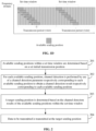
- FIG. 1A is a flowchart showing a data transmission method.
- FIG. 1B is a scenario diagram of a data transmission method.
- FIG. 1C is a first schematic diagram illustrating available sending positions within a set time window.
- FIG. 1D is a second schematic diagram illustrating available sending positions within a set time window.
- the data transmission method may be applied to data senders, for example, UE and a base station. As shown in FIG. 1A , the data transmission method includes the following operations 101-102.
- a target sending position is determined based on channel detection results of available sending positions within a set time window, a length of the set time window being associated with a type of data to be transmitted.
- the data to be transmitted may be signaling or signal that is periodically sent, for example, a DRS.
- the data to be transmitted may have different functions, for example, a signal for cell search and a signal for cell measurement.
- time windows with different lengths may be set, and a transmission opportunity of the signal in a period can be further regulated.
- a relatively long time window is configured for an important signal or signaling with a relatively high latency requirement.
- a transmission opportunity of the important signal or the signaling with the relatively high latency requirement can be increased.
- the length of the set time window does not exceed a transmission period of the data to be transmitted. For example, if a transmission period of a signal is configured by a base station to be one slot and a transmission length of the signal is two symbols, then a set time window with a length of eight symbols may be preconfigured.
- the set time window may be set by the base station based on the type of the data to be transmitted.
- the set time window may be predetermined by a system through a protocol.
- the available sending position within the set time window can be understood as a preconfigured position available for sending a signal within the set time window, and may be determined based on a preconfigured possible initial transmission position. For example, referring to FIG. 1C , the transmission period of a signal is one slot, the length of the set time window is eight symbols, and the transmission length of the signal is two symbols. In such case, preconfigured possible initial transmission positions are the first, third, fifth and seventh symbols, and then it can be determined that the available sending positions within the set time window are positions marked with signs 11, 12, 13 and 14.
- the available sending positions within the set time window may also be implicitly determined based on a set rule.
- the transmission period of a signal is one slot
- the length of a set time window is eight symbols
- the transmission length of the signal is two symbols.
- the preconfigured set rule is that any symbol within the set time window can be an available sending position, and then it can be determined that the available sending positions within the set time window are every symbol, i.e., the positions marked with signs 21, 22, 23, 24, 25, 26 and 27.
- the available sending positions marked with the signs 21, 22, 23, 24, 25, 26 and 27 correspond to different frequency-domain resources, but this is only schematic. Frequency-domain resources corresponding to data sending at the available sending positions may be the same or may also be different.
- the available sending position marked with the sign 11 can be directly determined as the target sending position, and channel detection is no more performed on the other subsequent available sending positions.
- the data may be tried to be sent at the next available sending position until the data is successfully sent.
- the data to be transmitted is transmitted at the target sending position.
- the data sender may send the data at the target sending position through a frequency-domain resource corresponding to the sending position.
- a mobile network is a new-generation network, for example, a 5th-Generation (5G) network
- a base station is a gNB as an example.
- the scenario shown in FIG. 1B includes the gNB 10 and UE 20.
- the data may be tried to be sent at multiple available sending positions within a set time window, so that the problem that predefined data to be transmitted cannot be sent due to a channel detection failure is solved.
- a set time window matched with the type of data to be transmitted can be configured for the data to be transmitted that is periodically sent. Multiple sending positions may be set in each set time window, and the length of a set time window is matched with the type of data to be transmitted. Therefore, through the technical solutions of the present disclosure, the signaling or signal transmission latency caused by channel uncertainties can be reduced, and transmission of a service with a relatively high latency requirement is ensured.
- FIG. 2 is a flowchart showing another data transmission method according to an exemplary embodiment, which is not claimed.
- exemplary descriptions are made based on the method provided in the embodiments of the present disclosure with the condition that a data sender determines available sending positions based on a set initial transmission position as an example. As shown in FIG. 2 , the following operations are included.
- available sending positions within a set time window are determined based on a set initial transmission position.
- a length of the set time window is associated with a type of data to be transmitted.
- the data to be transmitted may be signaling or signal that is periodically sent, and the length of the set time window does not exceed a transmission period of the data to be transmitted.
- the set time window may be set by a base station and sent to UE through RRC signaling, a MAC CE or physical-layer signaling.
- the set time window may be predetermined by a system through a protocol.
- the available sending position within the set time window can be understood as a preconfigured position available for sending a signal within the set time window, and may be determined based on the set possible initial transmission position. For example, referring to FIG. 1C , the transmission period of a signal is one slot, the length of a set time window is eight symbols, and the transmission length of the signal is two symbols. In such case, preconfigured possible initial transmission positions are the first, third, fifth and seventh symbols, and then it can be determined that the available sending positions within the set time window are positions marked with signs 11, 12, 13 and 14.
- the set initial position may be set by the base station and sent to the UE through the RRC signaling, the MAC CE or the physical-layer signaling.
- the set initial position may be predetermined by a system through a protocol.
- channel detection is performed by use of a channel detection parameter respectively corresponding to each available sending position to obtain a channel detection result respectively corresponding to each available sending position.
- a target sending position is determined based on the channel detection results of the available sending positions within the set time window.
- the first available sending position may be directly determined as the target sending position.
- channel detection may be sequentially performed on the next available sending position until the target sending position where the data can be sent is detected.
- data to be transmitted is transmitted at the target sending position.
- the data sender may send the data to be transmitted at the target sending position through a frequency-domain resource corresponding to the sending position.
- the data sender may determine all the available sending positions based on the preconfigured set initial transmission position and further determine the target sending position from the available sending positions, so that the signaling or signal transmission latency caused by channel uncertainties can be effectively reduced.
- FIG. 3 is a flowchart showing another data transmission method according to an exemplary embodiment, which is not claimed.
- exemplary descriptions are made based on the method provided in the embodiments of the present disclosure with the condition that a data sender determines available sending positions based on a set rule as an example. As shown in FIG. 3 , the following operations are included.
- available sending positions within a set time window are determined based on a set rule.
- the set rule may be set by a base station and sent to UE through RRC signaling, a MAC CE or physical-layer signaling.
- the set rule may be predetermined by a system through a protocol.
- the set rule may be a rule of determining the available sending positions. That is, the set rule may be configured to determine specific resource positions for data transmission. For example, the set rule may be that any symbol within the set time window may be an available sending position, referring to FIG. 1D .
- the set rule may also be some other rules apparent to those skilled in the art and configured to indicate the resource positions.
- channel detection is performed by use of a channel detection parameter respectively corresponding to each available sending position to obtain a channel detection result respectively corresponding to each available sending position.
- a target sending position is determined based on the channel detection results of the available sending positions within the set time window.
- Descriptions about operation 302 to operation 304 may refer to the descriptions about operation 202 to operation 204 in the embodiment shown in FIG. 2 and elaborations are omitted herein.
- the data sender may determine all the available sending positions based on the set rule and further determine the target sending position in the available sending positions, so that the signaling or signal transmission latency caused by channel uncertainties may be effectively reduced.
- FIG. 4 is a flowchart showing a data transmission method according to an exemplary embodiment, which is not claimed.
- the data transmission method may be applied to data receivers, for example, UE and a base station. As shown in FIG. 4 , the data transmission method includes the following operations 401-402.
- a receiving position configured to listen data to be transmitted within a set time window is determined, a length of the set time window being associated with a type of the data to be transmitted and the data to be transmitted being signaling or a signal that is periodically sent.
- the set time window may be set by a base station based on the type of data to be transmitted and may be sent to UE through RRC signaling, a MAC CE or physical-layer signaling. Or, the set time window may be predetermined in a protocol.
- the receiving position within the set time window may be determined based on a set initial transmission position. For example, referring to FIG. 1C , a transmission period of a signal is one slot, the length of the set time window is eight symbols, and a transmission length of the signal is two symbols. In such case, preconfigured possible initial transmission positions are the first, third, fifth and seventh symbols, and then it may be determined that the receiving position within the set time window is positions marked with signs 11, 12, 13 and 14.
- the receiving position within the set time window may be determined based on a set rule.
- the preconfigured set rule may be that any symbol within the set time window may be an available sending position, and then it can be determined that available sending positions within the set time window are all the symbols, namely the receiving position configured to listen the data to be transmitted within the set time window is the whole set time window.
- the set initial transmission position or the set rule may be configured by the base station and sent to the UE through the RRC signaling, the MAC CE or the physical-layer signaling.
- the set initial transmission position or the set rule may also be predetermined by a system through a protocol.
- the data to be transmitted is listened at the receiving position.
- the terminal may not continue listening the data to be transmitted at subsequent receiving positions.
- a data receiver determines a receiving position based on a set time window and a set initial transmission position or a set rule configured by a base station or by a system through a protocol and listens the data to be transmitted.
- the data receiver may listen the data to be transmitted at the receiving position within the set time window, so that the signal transmission latency caused by channel uncertainties during data transmission in an unlicensed spectrum can be effectively reduced.
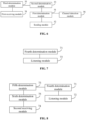
- FIG. 5 is a block diagram of a data transmission device according to an exemplary embodiment, which is not claimed.
- the data transmission device is applied to a data sender. As shown in FIG. 5 , the data transmission device includes:
- FIG. 6 is a block diagram of a device applicable to data transmission according to an exemplary embodiment, which is not claimed.
- the set time window is set by a base station based on the type of the data to be transmitted; or, the set time window is predetermined in a protocol.
- the device may further include: a second determination module 53, configured to determine the available sending positions within the set time window based on a set initial transmission position, or, determine the available sending positions within the set time window based on a set rule.
- a second determination module 53 configured to determine the available sending positions within the set time window based on a set initial transmission position, or, determine the available sending positions within the set time window based on a set rule.
- the set initial transmission position or the set rule may be set by the base station; or, the set initial transmission position or the set rule may be predetermined in the protocol.
- the device may further include:
- the first determination module 51 is configured to determine a first available sending position of which a channel detection result is an unoccupied state from the available sending positions within the set time window as the target sending position.
- the device may further include: a channel detection module 56, configured to, for each available sending position, perform channel detection by use of a channel detection parameter respectively corresponding to each available sending position to obtain a channel detection result respectively corresponding to each available sending position.
- a channel detection module 56 configured to, for each available sending position, perform channel detection by use of a channel detection parameter respectively corresponding to each available sending position to obtain a channel detection result respectively corresponding to each available sending position.
- FIG. 7 is a block diagram of a data transmission device according to an exemplary embodiment, which is not claimed.
- the data transmission device is applied to a data receiver.
- the data transmission device includes:
- FIG. 8 is a block diagram of a device applicable to data transmission according to an exemplary embodiment, which is not claimed. As shown in FIG. 8 , based on the embodiment shown in FIG. 7 , the set time window is set by a base station based on the type of the data to be transmitted; or, the set time window is predetermined in a protocol in an embodiment.
- the device may further include: a fifth determination module 73, configured to determine the receiving position within the set time window based on a set initial transmission position, or, determine the receiving position within the set time window based on a set rule.
- a fifth determination module 73 configured to determine the receiving position within the set time window based on a set initial transmission position, or, determine the receiving position within the set time window based on a set rule.
- the device may further include:
- the technical solutions provided in the present disclosure may be applied to UE in FIG. 9 and may also be applied to a base station in FIG. 10 .
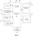
- FIG. 9 is a block diagram of a device applicable to data transmission according to an exemplary embodiment, which is not claimed.
- the device 900 may be UE such as a mobile phone, a computer, a digital broadcast terminal, a messaging device, a gaming console, a tablet, a medical device, exercise equipment and a personal digital assistant.
- the device 900 may include one or more of the following components: a processing component 902, a memory 904, a power component 906, a multimedia component 908, an audio component 912, an Input/Output (I/O) interface 912, a sensor component 914, and a communication component 916.
- the processing component 902 typically controls overall operations of the device 900, such as the operations associated with display, telephone calls, data communications, camera operations, and recording operations.
- the processing component 902 may include one or more processors 920 to execute instructions to perform all or part of the operations in the abovementioned methods.
- the processing component 902 may include one or more modules which facilitate interaction between the processing component 902 and the other components.
- the processing component 902 may include a multimedia module to facilitate interaction between the multimedia component 908 and the processing component 902.
- the memory 904 is configured to store various types of data to support the operation of the device 900. Examples of such data include instructions for any applications or methods operated on the device 900, contact data, phonebook data, messages, pictures, video, etc.
- the memory 904 may be implemented by any type of volatile or non-volatile memory devices, or a combination thereof, such as a Static Random Access Memory (SRAM), an Electrically Erasable Programmable Read-Only Memory (EEPROM), an Erasable Programmable Read-Only Memory (EPROM), a Programmable Read-Only Memory (PROM), a Read-Only Memory (ROM), a magnetic memory, a flash memory, and a magnetic or optical disk.
- SRAM Static Random Access Memory
- EEPROM Electrically Erasable Programmable Read-Only Memory
- EPROM Erasable Programmable Read-Only Memory
- PROM Programmable Read-Only Memory
- ROM Read-Only Memory
- magnetic memory a magnetic memory
- flash memory and a magnetic or optical disk.
- the power component 906 provides power for various components of the device 900.
- the power component 906 may include a power management system, one or more power supplies, and other components associated with generation, management and distribution of power for the device 900.
- the multimedia component 908 includes a screen providing an output interface between the device 900 and a user.
- the screen may include a Liquid Crystal Display (LCD) and a Touch Panel (TP). If the screen includes the TP, the screen may be implemented as a touch screen to receive an input signal from the user.
- the TP includes one or more touch sensors to sense touches, swipes and gestures on the TP. The touch sensors may not only sense a boundary of a touch or swipe action but also detect a duration and pressure associated with the touch or swipe action.
- the multimedia component 908 includes a front camera and/or a rear camera.
- the front camera and/or the rear camera may receive external multimedia data when the device 900 is in an operation mode, such as a photographing mode or a video mode.
- an operation mode such as a photographing mode or a video mode.
- Each of the front camera and the rear camera may be a fixed optical lens system or have focusing and optical zooming capabilities.
- the audio component 912 is configured to output and/or input an audio signal.
- the audio component 912 includes a Microphone (MIC), and the MIC is configured to receive an external audio signal when the device 900 is in the operation mode, such as a call mode, a recording mode and a voice recognition mode.
- the received audio signal may further be stored in the memory 904 or sent through the communication component 916.
- the audio component 912 may further include a speaker configured to output the audio signal.
- the I/O interface 912 provides an interface between the processing component 902 and a peripheral interface module, and the peripheral interface module may be a keyboard, a click wheel, a button and the like.
- the button may include, but not limited to: a home button, a volume button, a starting button and a locking button.
- the sensor component 914 includes one or more sensors configured to provide status assessment in various aspects for the device 900. For instance, the sensor component 914 may detect an on/off status of the device 900 and relative positioning of components, such as a display and small keyboard of the device 900, and the sensor component 914 may further detect a change in a position of the device 900 or a component of the device 900, presence or absence of contact between the user and the device 900, orientation or acceleration/deceleration of the device 900 and a change in temperature of the device 900.
- the sensor component 914 may include a proximity sensor configured to detect presence of an object nearby without any physical contact.
- the sensor component 914 may also include a light sensor, such as a Complementary Metal Oxide Semiconductor (CMOS) or Charge Coupled Device (CCD) image sensor, configured for use in an imaging application.
- CMOS Complementary Metal Oxide Semiconductor
- CCD Charge Coupled Device
- the sensor component 914 may also include an acceleration sensor, a gyroscope sensor, a magnetic sensor, a pressure sensor or a temperature sensor.
- the communication component 916 is configured to facilitate wired or wireless communication between the device 900 and another device.
- the device 900 may access a communication-standard-based wireless network, such as a WIFI network, a 2nd-Generation (2G) or 3rd-Generation (3G) network or a combination thereof.
- the communication component 916 receives a broadcast signal or broadcast associated information from an external broadcast management system through a broadcast channel.
- the communication component 916 may further include a Near Field Communication (NFC) module to facilitate short-range communication.
- NFC Near Field Communication
- the NFC module may be implemented based on a Radio Frequency Identification (RFID) technology, an Infrared Data Association (IrDA) technology, an Ultra-Wide Band (UWB) technology, a Bluetooth (BT) technology and another technology.
- RFID Radio Frequency Identification
- IrDA Infrared Data Association
- UWB Ultra-Wide Band
- BT Bluetooth
- the device 900 may be implemented by one or more Application Specific Integrated Circuits (ASICs), Digital Signal Processors (DSPs), Digital Signal Processing Devices (DSPDs), Programmable Logic Devices (PLDs), Field Programmable Gate Arrays (FPGAs), controllers, micro-controllers, microprocessors or other electronic components, and is configured to execute the method described according to the first aspect or the second aspect.
- ASICs Application Specific Integrated Circuits
- DSPs Digital Signal Processors
- DSPDs Digital Signal Processing Devices
- PLDs Programmable Logic Devices
- FPGAs Field Programmable Gate Arrays
- controllers micro-controllers, microprocessors or other electronic components, and is configured to execute the method described according to the first aspect or the second aspect.
- Non-transitory computer-readable storage medium including instructions, such as the memory 904 including instructions, and the instructions may be executed to cause the processor 920 of the device 900 to implement the method described according to the first aspect or the second aspect.
- FIG. 10 is a block diagram of a device applicable to data transmission.
- the device 1000 may be provided as a base station.
- the device 1000 includes a processing component 1022, a wireless transmission/receiving component 1024, an antenna component 1026 and a wireless interface-specific signal processing part, and the processing component 1022 may further include one or more processors.
- One processor in the processing component 1022 may be configured to implement the method described according to the first aspect or the second aspect.
- a non-transitory computer-readable storage medium including instructions is also provided in a base station, in which computer instructions are stored, the instructions being executed by a processor to implement the method described according to the first aspect or the second aspect.
Landscapes
- Engineering & Computer Science (AREA)
- Signal Processing (AREA)
- Computer Networks & Wireless Communication (AREA)
- Quality & Reliability (AREA)
- Mobile Radio Communication Systems (AREA)
Claims (15)
- Un procédé de transmission de données, mis en oeuvre par un expéditeur de données, le procédé comprenant :déterminer (101) une position d'envoi cible sur la base de résultats de détection de canal de positions d'envoi disponibles dans une fenêtre temporelle définie, caractérisé en ce qu'une longueur de la fenêtre temporelle définie est associée à un type de données à transmettre, les données à transmettre sont une signalisation ou un signal qui est périodiquement envoyé, la longueur de la fenêtre temporelle définie ne dépasse pas une période de transmission des données à transmettre, et une longueur d'une fenêtre temporelle définie pour un signal important ou une signalisation avec une exigence de latence relativement élevée est supérieure à une longueur d'une fenêtre temporelle définie pour d'autres signaux ou signalisations ; ettransmettre (102) les données à la position d'envoi cible.
- Le procédé selon la revendication 1, dans lequel la fenêtre temporelle définie est définie par une station de base sur la base du type des données à transmettre ; ou, la fenêtre temporelle définie est prédéterminée dans un protocole.
- Le procédé selon la revendication 1, comprenant en outre :déterminer (201) les positions d'envoi disponibles dans la fenêtre temporelle définie sur la base d'une position de transmission initiale définie ; ou,déterminer (301) les positions d'envoi disponibles dans la fenêtre temporelle définie sur la base d'une règle définie.
- Le procédé selon la revendication 3, dans lequel la position de transmission initiale définie ou la règle définie est définie par la station de base ; ou, la position de transmission initiale définie ou la règle définie est prédéterminée dans le protocole.
- Le procédé selon la revendication 3, dans lequel quand l'expéditeur de données est un équipement utilisateur, UE, le procédé comprend en outre :recevoir une signalisation de contrôle de ressources radio, RRC, ou un élément de contrôle, CE, de contrôle d'accès au support, MAC, ou une signalisation de couche physique à partir de la station de base ; etdéterminer la fenêtre temporelle définie et déterminer la position de transmission initiale définie ou la règle définie sur la base de la signalisation RRC, ou du CE MAC ou de la signalisation de couche physique.
- Le procédé selon la revendication 1, dans lequel déterminer la position d'envoi cible sur la base des résultats de détection de canal des positions d'envoi disponibles dans la fenêtre temporelle définie comprend :
déterminer une première position d'envoi disponible dont un résultat de détection de canal est un état inoccupé à partir des positions d'envoi disponibles dans la fenêtre temporelle définie en tant que position d'envoi cible. - Le procédé selon la revendication 1, comprenant en outre :
pour chaque position d'envoi disponible, effectuer (202, 302) une détection de canal en utilisant un paramètre de détection de canal correspondant respectivement à chaque position d'envoi disponible pour obtenir un résultat de détection de canal correspondant respectivement à chaque position d'envoi disponible. - Un procédé de transmission de données, mis en oeuvre par un récepteur de données, le procédé comprenant :déterminer (401) une position de réception configurée pour écouter des données à transmettre dans une fenêtre temporelle définie, caractérisé en ce qu'une longueur de la fenêtre temporelle définie est associée à un type des données à transmettre et que les données à transmettre sont une signalisation ou un signal qui est périodiquement envoyé, et qu'une longueur d'une fenêtre temporelle définie pour un signal important ou une signalisation importante avec une exigence de latence relativement élevée est supérieure à une longueur d'une fenêtre temporelle définie pour d'autres signaux ou signalisations ; etécouter (402) les données à transmettre à la position de réception.
- Le procédé selon la revendication 8, dans lequel la fenêtre temporelle définie est définie par une station de base sur la base du type des données à transmettre ; ou, la fenêtre temporelle définie est prédéterminée dans un protocole.
- Le procédé selon la revendication 8, comprenant en outre :déterminer la position de réception dans la fenêtre temporelle définie sur la base d'une position de transmission initiale définie ; ou,déterminer la position de réception dans la fenêtre temporelle définie sur la base d'une règle définie.
- Le procédé selon la revendication 10, dans lequel quand le récepteur de données est un équipement utilisateur, UE, le procédé comprend en outre :recevoir une signalisation de contrôle de ressources radio, RRC, ou un élément de contrôle, CE, de contrôle d'accès au support, MAC, ou une signalisation de couche physique à partir de la station de base ; etdéterminer la fenêtre temporelle définie et déterminer la position de transmission initiale définie ou la règle définie sur la base de la signalisation RRC, ou du CE MAC ou de la signalisation de couche physique.
- Un expéditeur de données, comprenant :un processeur ; etune mémoire configurée pour stocker des instructions exécutables par un processeur,dans lequel le processeur est configuré pour mettre en oeuvre des opérations du procédé selon l'une quelconque des revendications 1-7.
- Un récepteur de données, comprenant :un processeur ; etune mémoire configurée pour stocker des instructions exécutables par un processeur,dans lequel le processeur est configuré pour mettre en oeuvre des opérations du procédé selon l'une quelconque des revendications 8-11.
- Un support de stockage non transitoire lisible par ordinateur, sur lequel sont stockées des instructions informatiques exécutables par un processeur pour mettre en oeuvre des opérations du procédé selon l'une quelconque des revendications 1-7.
- Un support de stockage non transitoire lisible par ordinateur, sur lequel sont stockées des instructions informatiques exécutables par un processeur pour mettre en oeuvre des opérations du procédé selon l'une quelconque des revendications 8-11.
Applications Claiming Priority (1)
| Application Number | Priority Date | Filing Date | Title |
|---|---|---|---|
| PCT/CN2018/081398 WO2019183939A1 (fr) | 2018-03-30 | 2018-03-30 | Procédé et dispositif de transmission de données |
Publications (3)
| Publication Number | Publication Date |
|---|---|
| EP3771276A1 EP3771276A1 (fr) | 2021-01-27 |
| EP3771276A4 EP3771276A4 (fr) | 2021-11-24 |
| EP3771276B1 true EP3771276B1 (fr) | 2023-10-25 |
Family
ID=65540257
Family Applications (1)
| Application Number | Title | Priority Date | Filing Date |
|---|---|---|---|
| EP18911882.1A Active EP3771276B1 (fr) | 2018-03-30 | 2018-03-30 | Procédé et dispositif de transmission de données |
Country Status (4)
| Country | Link |
|---|---|
| US (1) | US11601934B2 (fr) |
| EP (1) | EP3771276B1 (fr) |
| CN (1) | CN109451803B (fr) |
| WO (1) | WO2019183939A1 (fr) |
Families Citing this family (2)
| Publication number | Priority date | Publication date | Assignee | Title |
|---|---|---|---|---|
| KR102547937B1 (ko) * | 2018-08-08 | 2023-06-26 | 삼성전자주식회사 | 무선 통신 시스템에서 데이터를 송수신하는 방법 및 장치 |
| CN114762414B (zh) * | 2020-11-10 | 2026-01-30 | 北京小米移动软件有限公司 | 数据传输方法、装置、基站、用户终端和电子设备 |
Family Cites Families (9)
| Publication number | Priority date | Publication date | Assignee | Title |
|---|---|---|---|---|
| CN105991210B (zh) * | 2015-01-28 | 2019-03-26 | 中国移动通信集团公司 | 一种非授权频段上的参考信号发送方法、接收方法及装置 |
| US10219159B2 (en) * | 2015-01-30 | 2019-02-26 | Electronics And Telecommunications Research Institute | Method and apparatus for transmitting and receiving reference signal using unlicensed band |
| WO2016186406A1 (fr) | 2015-05-16 | 2016-11-24 | 주식회사 윌러스표준기술연구소 | Procédé, dispositif et système permettant une transmission de signaux dans une bande non autorisée |
| US10778486B2 (en) * | 2015-08-13 | 2020-09-15 | Intel IP Corporation | Discovery reference signal design for LTE in unlicensed bands |
| CN111740812B (zh) * | 2016-04-01 | 2022-09-20 | 中兴通讯股份有限公司 | 探测参考信号发送方法 |
| US10492168B2 (en) * | 2016-05-03 | 2019-11-26 | Telefonaktiebolaget Lm Ericsson (Publ) | Paging detection utilizing a discovery reference signal (DRS) within a subframe time window |
| CN108282879B (zh) * | 2017-01-06 | 2022-11-18 | 中兴通讯股份有限公司 | 数据传输方法及装置 |
| MX385540B (es) * | 2017-11-24 | 2025-03-18 | Lg Electronics Inc | Método para reportar información de estado del canal en un sistema de comunicación inalámbrica y aparato para el mismo. |
| EP3509373B1 (fr) * | 2018-01-09 | 2023-03-08 | Comcast Cable Communications LLC | Sélection de faisceau dans une retransmission de demande de reprise après défaillance de faisceau |
-
2018
- 2018-03-30 WO PCT/CN2018/081398 patent/WO2019183939A1/fr not_active Ceased
- 2018-03-30 EP EP18911882.1A patent/EP3771276B1/fr active Active
- 2018-03-30 CN CN201880000370.1A patent/CN109451803B/zh active Active
-
2020
- 2020-08-28 US US17/006,567 patent/US11601934B2/en active Active
Also Published As
| Publication number | Publication date |
|---|---|
| EP3771276A1 (fr) | 2021-01-27 |
| US11601934B2 (en) | 2023-03-07 |
| WO2019183939A1 (fr) | 2019-10-03 |
| EP3771276A4 (fr) | 2021-11-24 |
| CN109451803B (zh) | 2022-04-08 |
| CN109451803A (zh) | 2019-03-08 |
| US20200396735A1 (en) | 2020-12-17 |
Similar Documents
| Publication | Publication Date | Title |
|---|---|---|
| US11483819B2 (en) | Data transmission method and apparatus and user equipment | |
| US11895630B2 (en) | Method and device for identifying downlink transmissions | |
| CN108496390B (zh) | 非授权小区中的数据传输方法及装置、基站和用户设备 | |
| EP3793278B1 (fr) | Appareil et procédé de synchronisation de radiomessagerie | |
| US11394515B2 (en) | Information transmission method, device, and system, and storage medium | |
| EP3952506A1 (fr) | Procédé et appareil d'indication de format d'intervalle | |
| US11864205B2 (en) | Scheduling method, base station, terminal and storage medium | |
| EP3644564A1 (fr) | Procédé et dispositif d'indication de transmission multiplex de données multi-service, terminal, et station de base | |
| EP3809772B1 (fr) | Procédé et dispositif permettant de déterminer des points de commutation de liaison montante et de liaison descendante | |
| US11601934B2 (en) | Data transmission method and device | |
| CN110506430B (zh) | 信道占用时间的起始位置确定方法、装置、设备和介质 | |
| EP3771269B1 (fr) | Procédé et dispositif de sélection de faisceau | |
| US11956755B2 (en) | Method and apparatus for transmitting paging signaling | |
| EP3876451B1 (fr) | Procédé et appareil de retour d'informations | |
| US11496281B2 (en) | Method and device for indicating transmission direction | |
| EP3883163B1 (fr) | Procédé et dispositif de transmission d'informations de commande et de données | |
| US11533728B2 (en) | Data transmission method and apparatus on unlicensed frequency band | |
| US11438123B2 (en) | Method and device for realizing signaling detection, user equipment, and base station | |
| CN116762412A (zh) | 一种信息传输和接收方法、装置、设备及存储介质 | |
| EP3902344A1 (fr) | Procédé et dispositif permettant d'indiquer un état d'occupation de ressource, et procédé et dispositif permettant de déterminer un état d'occupation de ressource | |
| EP3896883B1 (fr) | Procédé et dispositif de transmission de données | |
| CN117044325A (zh) | 一种确定唤醒信号周期的方法、装置、设备及存储介质 |
Legal Events
| Date | Code | Title | Description |
|---|---|---|---|
| STAA | Information on the status of an ep patent application or granted ep patent |
Free format text: STATUS: THE INTERNATIONAL PUBLICATION HAS BEEN MADE |
|
| PUAI | Public reference made under article 153(3) epc to a published international application that has entered the european phase |
Free format text: ORIGINAL CODE: 0009012 |
|
| STAA | Information on the status of an ep patent application or granted ep patent |
Free format text: STATUS: REQUEST FOR EXAMINATION WAS MADE |
|
| 17P | Request for examination filed |
Effective date: 20201021 |
|
| AK | Designated contracting states |
Kind code of ref document: A1 Designated state(s): AL AT BE BG CH CY CZ DE DK EE ES FI FR GB GR HR HU IE IS IT LI LT LU LV MC MK MT NL NO PL PT RO RS SE SI SK SM TR |
|
| AX | Request for extension of the european patent |
Extension state: BA ME |
|
| DAV | Request for validation of the european patent (deleted) | ||
| DAX | Request for extension of the european patent (deleted) | ||
| REG | Reference to a national code |
Ref country code: DE Ref legal event code: R079 Free format text: PREVIOUS MAIN CLASS: H04W0072120000 Ipc: H04W0074080000 Ref country code: DE Ref legal event code: R079 Ref document number: 602018060196 Country of ref document: DE Free format text: PREVIOUS MAIN CLASS: H04W0072120000 Ipc: H04W0074080000 |
|
| A4 | Supplementary search report drawn up and despatched |
Effective date: 20211022 |
|
| RIC1 | Information provided on ipc code assigned before grant |
Ipc: H04L 5/00 20060101ALI20211018BHEP Ipc: H04W 74/08 20090101AFI20211018BHEP |
|
| GRAP | Despatch of communication of intention to grant a patent |
Free format text: ORIGINAL CODE: EPIDOSNIGR1 |
|
| STAA | Information on the status of an ep patent application or granted ep patent |
Free format text: STATUS: GRANT OF PATENT IS INTENDED |
|
| INTG | Intention to grant announced |
Effective date: 20230629 |
|
| P01 | Opt-out of the competence of the unified patent court (upc) registered |
Effective date: 20230802 |
|
| GRAS | Grant fee paid |
Free format text: ORIGINAL CODE: EPIDOSNIGR3 |
|
| GRAA | (expected) grant |
Free format text: ORIGINAL CODE: 0009210 |
|
| STAA | Information on the status of an ep patent application or granted ep patent |
Free format text: STATUS: THE PATENT HAS BEEN GRANTED |
|
| AK | Designated contracting states |
Kind code of ref document: B1 Designated state(s): AL AT BE BG CH CY CZ DE DK EE ES FI FR GB GR HR HU IE IS IT LI LT LU LV MC MK MT NL NO PL PT RO RS SE SI SK SM TR |
|
| REG | Reference to a national code |
Ref country code: GB Ref legal event code: FG4D |
|
| REG | Reference to a national code |
Ref country code: CH Ref legal event code: EP |
|
| REG | Reference to a national code |
Ref country code: DE Ref legal event code: R096 Ref document number: 602018060196 Country of ref document: DE |
|
| REG | Reference to a national code |
Ref country code: IE Ref legal event code: FG4D |
|
| REG | Reference to a national code |
Ref country code: LT Ref legal event code: MG9D |
|
| REG | Reference to a national code |
Ref country code: NL Ref legal event code: MP Effective date: 20231025 |
|
| REG | Reference to a national code |
Ref country code: AT Ref legal event code: MK05 Ref document number: 1626027 Country of ref document: AT Kind code of ref document: T Effective date: 20231025 |
|
| PG25 | Lapsed in a contracting state [announced via postgrant information from national office to epo] |
Ref country code: NL Free format text: LAPSE BECAUSE OF FAILURE TO SUBMIT A TRANSLATION OF THE DESCRIPTION OR TO PAY THE FEE WITHIN THE PRESCRIBED TIME-LIMIT Effective date: 20231025 |
|
| PG25 | Lapsed in a contracting state [announced via postgrant information from national office to epo] |
Ref country code: GR Free format text: LAPSE BECAUSE OF FAILURE TO SUBMIT A TRANSLATION OF THE DESCRIPTION OR TO PAY THE FEE WITHIN THE PRESCRIBED TIME-LIMIT Effective date: 20240126 |
|
| PG25 | Lapsed in a contracting state [announced via postgrant information from national office to epo] |
Ref country code: IS Free format text: LAPSE BECAUSE OF FAILURE TO SUBMIT A TRANSLATION OF THE DESCRIPTION OR TO PAY THE FEE WITHIN THE PRESCRIBED TIME-LIMIT Effective date: 20240225 |
|
| PG25 | Lapsed in a contracting state [announced via postgrant information from national office to epo] |
Ref country code: LT Free format text: LAPSE BECAUSE OF FAILURE TO SUBMIT A TRANSLATION OF THE DESCRIPTION OR TO PAY THE FEE WITHIN THE PRESCRIBED TIME-LIMIT Effective date: 20231025 |
|
| PG25 | Lapsed in a contracting state [announced via postgrant information from national office to epo] |
Ref country code: AT Free format text: LAPSE BECAUSE OF FAILURE TO SUBMIT A TRANSLATION OF THE DESCRIPTION OR TO PAY THE FEE WITHIN THE PRESCRIBED TIME-LIMIT Effective date: 20231025 |
|
| PG25 | Lapsed in a contracting state [announced via postgrant information from national office to epo] |
Ref country code: ES Free format text: LAPSE BECAUSE OF FAILURE TO SUBMIT A TRANSLATION OF THE DESCRIPTION OR TO PAY THE FEE WITHIN THE PRESCRIBED TIME-LIMIT Effective date: 20231025 |
|
| PG25 | Lapsed in a contracting state [announced via postgrant information from national office to epo] |
Ref country code: LT Free format text: LAPSE BECAUSE OF FAILURE TO SUBMIT A TRANSLATION OF THE DESCRIPTION OR TO PAY THE FEE WITHIN THE PRESCRIBED TIME-LIMIT Effective date: 20231025 Ref country code: IS Free format text: LAPSE BECAUSE OF FAILURE TO SUBMIT A TRANSLATION OF THE DESCRIPTION OR TO PAY THE FEE WITHIN THE PRESCRIBED TIME-LIMIT Effective date: 20240225 Ref country code: GR Free format text: LAPSE BECAUSE OF FAILURE TO SUBMIT A TRANSLATION OF THE DESCRIPTION OR TO PAY THE FEE WITHIN THE PRESCRIBED TIME-LIMIT Effective date: 20240126 Ref country code: ES Free format text: LAPSE BECAUSE OF FAILURE TO SUBMIT A TRANSLATION OF THE DESCRIPTION OR TO PAY THE FEE WITHIN THE PRESCRIBED TIME-LIMIT Effective date: 20231025 Ref country code: BG Free format text: LAPSE BECAUSE OF FAILURE TO SUBMIT A TRANSLATION OF THE DESCRIPTION OR TO PAY THE FEE WITHIN THE PRESCRIBED TIME-LIMIT Effective date: 20240125 Ref country code: AT Free format text: LAPSE BECAUSE OF FAILURE TO SUBMIT A TRANSLATION OF THE DESCRIPTION OR TO PAY THE FEE WITHIN THE PRESCRIBED TIME-LIMIT Effective date: 20231025 Ref country code: PT Free format text: LAPSE BECAUSE OF FAILURE TO SUBMIT A TRANSLATION OF THE DESCRIPTION OR TO PAY THE FEE WITHIN THE PRESCRIBED TIME-LIMIT Effective date: 20240226 |
|
| PG25 | Lapsed in a contracting state [announced via postgrant information from national office to epo] |
Ref country code: SE Free format text: LAPSE BECAUSE OF FAILURE TO SUBMIT A TRANSLATION OF THE DESCRIPTION OR TO PAY THE FEE WITHIN THE PRESCRIBED TIME-LIMIT Effective date: 20231025 Ref country code: RS Free format text: LAPSE BECAUSE OF FAILURE TO SUBMIT A TRANSLATION OF THE DESCRIPTION OR TO PAY THE FEE WITHIN THE PRESCRIBED TIME-LIMIT Effective date: 20231025 Ref country code: PL Free format text: LAPSE BECAUSE OF FAILURE TO SUBMIT A TRANSLATION OF THE DESCRIPTION OR TO PAY THE FEE WITHIN THE PRESCRIBED TIME-LIMIT Effective date: 20231025 Ref country code: NO Free format text: LAPSE BECAUSE OF FAILURE TO SUBMIT A TRANSLATION OF THE DESCRIPTION OR TO PAY THE FEE WITHIN THE PRESCRIBED TIME-LIMIT Effective date: 20240125 Ref country code: LV Free format text: LAPSE BECAUSE OF FAILURE TO SUBMIT A TRANSLATION OF THE DESCRIPTION OR TO PAY THE FEE WITHIN THE PRESCRIBED TIME-LIMIT Effective date: 20231025 Ref country code: HR Free format text: LAPSE BECAUSE OF FAILURE TO SUBMIT A TRANSLATION OF THE DESCRIPTION OR TO PAY THE FEE WITHIN THE PRESCRIBED TIME-LIMIT Effective date: 20231025 |
|
| PG25 | Lapsed in a contracting state [announced via postgrant information from national office to epo] |
Ref country code: DK Free format text: LAPSE BECAUSE OF FAILURE TO SUBMIT A TRANSLATION OF THE DESCRIPTION OR TO PAY THE FEE WITHIN THE PRESCRIBED TIME-LIMIT Effective date: 20231025 |
|
| PG25 | Lapsed in a contracting state [announced via postgrant information from national office to epo] |
Ref country code: CZ Free format text: LAPSE BECAUSE OF FAILURE TO SUBMIT A TRANSLATION OF THE DESCRIPTION OR TO PAY THE FEE WITHIN THE PRESCRIBED TIME-LIMIT Effective date: 20231025 |
|
| REG | Reference to a national code |
Ref country code: DE Ref legal event code: R097 Ref document number: 602018060196 Country of ref document: DE |
|
| PG25 | Lapsed in a contracting state [announced via postgrant information from national office to epo] |
Ref country code: SK Free format text: LAPSE BECAUSE OF FAILURE TO SUBMIT A TRANSLATION OF THE DESCRIPTION OR TO PAY THE FEE WITHIN THE PRESCRIBED TIME-LIMIT Effective date: 20231025 |
|
| PG25 | Lapsed in a contracting state [announced via postgrant information from national office to epo] |
Ref country code: SM Free format text: LAPSE BECAUSE OF FAILURE TO SUBMIT A TRANSLATION OF THE DESCRIPTION OR TO PAY THE FEE WITHIN THE PRESCRIBED TIME-LIMIT Effective date: 20231025 Ref country code: SK Free format text: LAPSE BECAUSE OF FAILURE TO SUBMIT A TRANSLATION OF THE DESCRIPTION OR TO PAY THE FEE WITHIN THE PRESCRIBED TIME-LIMIT Effective date: 20231025 Ref country code: RO Free format text: LAPSE BECAUSE OF FAILURE TO SUBMIT A TRANSLATION OF THE DESCRIPTION OR TO PAY THE FEE WITHIN THE PRESCRIBED TIME-LIMIT Effective date: 20231025 Ref country code: IT Free format text: LAPSE BECAUSE OF FAILURE TO SUBMIT A TRANSLATION OF THE DESCRIPTION OR TO PAY THE FEE WITHIN THE PRESCRIBED TIME-LIMIT Effective date: 20231025 Ref country code: EE Free format text: LAPSE BECAUSE OF FAILURE TO SUBMIT A TRANSLATION OF THE DESCRIPTION OR TO PAY THE FEE WITHIN THE PRESCRIBED TIME-LIMIT Effective date: 20231025 Ref country code: DK Free format text: LAPSE BECAUSE OF FAILURE TO SUBMIT A TRANSLATION OF THE DESCRIPTION OR TO PAY THE FEE WITHIN THE PRESCRIBED TIME-LIMIT Effective date: 20231025 Ref country code: CZ Free format text: LAPSE BECAUSE OF FAILURE TO SUBMIT A TRANSLATION OF THE DESCRIPTION OR TO PAY THE FEE WITHIN THE PRESCRIBED TIME-LIMIT Effective date: 20231025 |
|
| PLBE | No opposition filed within time limit |
Free format text: ORIGINAL CODE: 0009261 |
|
| STAA | Information on the status of an ep patent application or granted ep patent |
Free format text: STATUS: NO OPPOSITION FILED WITHIN TIME LIMIT |
|
| 26N | No opposition filed |
Effective date: 20240726 |
|
| PG25 | Lapsed in a contracting state [announced via postgrant information from national office to epo] |
Ref country code: SI Free format text: LAPSE BECAUSE OF FAILURE TO SUBMIT A TRANSLATION OF THE DESCRIPTION OR TO PAY THE FEE WITHIN THE PRESCRIBED TIME-LIMIT Effective date: 20231025 |
|
| PG25 | Lapsed in a contracting state [announced via postgrant information from national office to epo] |
Ref country code: SI Free format text: LAPSE BECAUSE OF FAILURE TO SUBMIT A TRANSLATION OF THE DESCRIPTION OR TO PAY THE FEE WITHIN THE PRESCRIBED TIME-LIMIT Effective date: 20231025 |
|
| REG | Reference to a national code |
Ref country code: CH Ref legal event code: PL |
|
| PG25 | Lapsed in a contracting state [announced via postgrant information from national office to epo] |
Ref country code: LU Free format text: LAPSE BECAUSE OF NON-PAYMENT OF DUE FEES Effective date: 20240330 |
|
| PG25 | Lapsed in a contracting state [announced via postgrant information from national office to epo] |
Ref country code: MC Free format text: LAPSE BECAUSE OF FAILURE TO SUBMIT A TRANSLATION OF THE DESCRIPTION OR TO PAY THE FEE WITHIN THE PRESCRIBED TIME-LIMIT Effective date: 20231025 |
|
| PG25 | Lapsed in a contracting state [announced via postgrant information from national office to epo] |
Ref country code: MC Free format text: LAPSE BECAUSE OF FAILURE TO SUBMIT A TRANSLATION OF THE DESCRIPTION OR TO PAY THE FEE WITHIN THE PRESCRIBED TIME-LIMIT Effective date: 20231025 Ref country code: LU Free format text: LAPSE BECAUSE OF NON-PAYMENT OF DUE FEES Effective date: 20240330 |
|
| REG | Reference to a national code |
Ref country code: BE Ref legal event code: MM Effective date: 20240331 |
|
| PG25 | Lapsed in a contracting state [announced via postgrant information from national office to epo] |
Ref country code: BE Free format text: LAPSE BECAUSE OF NON-PAYMENT OF DUE FEES Effective date: 20240331 |
|
| PG25 | Lapsed in a contracting state [announced via postgrant information from national office to epo] |
Ref country code: IE Free format text: LAPSE BECAUSE OF NON-PAYMENT OF DUE FEES Effective date: 20240330 |
|
| PG25 | Lapsed in a contracting state [announced via postgrant information from national office to epo] |
Ref country code: IE Free format text: LAPSE BECAUSE OF NON-PAYMENT OF DUE FEES Effective date: 20240330 Ref country code: BE Free format text: LAPSE BECAUSE OF NON-PAYMENT OF DUE FEES Effective date: 20240331 Ref country code: CH Free format text: LAPSE BECAUSE OF NON-PAYMENT OF DUE FEES Effective date: 20240331 |
|
| PG25 | Lapsed in a contracting state [announced via postgrant information from national office to epo] |
Ref country code: CY Free format text: LAPSE BECAUSE OF FAILURE TO SUBMIT A TRANSLATION OF THE DESCRIPTION OR TO PAY THE FEE WITHIN THE PRESCRIBED TIME-LIMIT; INVALID AB INITIO Effective date: 20180330 |
|
| PG25 | Lapsed in a contracting state [announced via postgrant information from national office to epo] |
Ref country code: HU Free format text: LAPSE BECAUSE OF FAILURE TO SUBMIT A TRANSLATION OF THE DESCRIPTION OR TO PAY THE FEE WITHIN THE PRESCRIBED TIME-LIMIT; INVALID AB INITIO Effective date: 20180330 |
|
| PG25 | Lapsed in a contracting state [announced via postgrant information from national office to epo] |
Ref country code: FI Free format text: LAPSE BECAUSE OF FAILURE TO SUBMIT A TRANSLATION OF THE DESCRIPTION OR TO PAY THE FEE WITHIN THE PRESCRIBED TIME-LIMIT Effective date: 20231025 |
|
| PG25 | Lapsed in a contracting state [announced via postgrant information from national office to epo] |
Ref country code: TR Free format text: LAPSE BECAUSE OF FAILURE TO SUBMIT A TRANSLATION OF THE DESCRIPTION OR TO PAY THE FEE WITHIN THE PRESCRIBED TIME-LIMIT Effective date: 20231025 |
|
| PGFP | Annual fee paid to national office [announced via postgrant information from national office to epo] |
Ref country code: GB Payment date: 20260325 Year of fee payment: 9 |
|
| PGFP | Annual fee paid to national office [announced via postgrant information from national office to epo] |
Ref country code: DE Payment date: 20260324 Year of fee payment: 9 |
|
| PGFP | Annual fee paid to national office [announced via postgrant information from national office to epo] |
Ref country code: FR Payment date: 20260330 Year of fee payment: 9 |