EP3771407B1 - Vorrichtung zur überwachung physiologischer signale - Google Patents
Vorrichtung zur überwachung physiologischer signale Download PDFInfo
- Publication number
- EP3771407B1 EP3771407B1 EP20188961.5A EP20188961A EP3771407B1 EP 3771407 B1 EP3771407 B1 EP 3771407B1 EP 20188961 A EP20188961 A EP 20188961A EP 3771407 B1 EP3771407 B1 EP 3771407B1
- Authority
- EP
- European Patent Office
- Prior art keywords
- physiological signal
- sensing member
- monitoring device
- socket
- signal monitoring
- Prior art date
- Legal status (The legal status is an assumption and is not a legal conclusion. Google has not performed a legal analysis and makes no representation as to the accuracy of the status listed.)
- Active
Links
Images










Classifications
-
- A—HUMAN NECESSITIES
- A61—MEDICAL OR VETERINARY SCIENCE; HYGIENE
- A61B—DIAGNOSIS; SURGERY; IDENTIFICATION
- A61B5/00—Measuring for diagnostic purposes; Identification of persons
- A61B5/0002—Remote monitoring of patients using telemetry, e.g. transmission of vital signals via a communication network
-
- A—HUMAN NECESSITIES
- A61—MEDICAL OR VETERINARY SCIENCE; HYGIENE
- A61B—DIAGNOSIS; SURGERY; IDENTIFICATION
- A61B5/00—Measuring for diagnostic purposes; Identification of persons
- A61B5/0002—Remote monitoring of patients using telemetry, e.g. transmission of vital signals via a communication network
- A61B5/0031—Implanted circuitry
-
- A—HUMAN NECESSITIES
- A61—MEDICAL OR VETERINARY SCIENCE; HYGIENE
- A61B—DIAGNOSIS; SURGERY; IDENTIFICATION
- A61B5/00—Measuring for diagnostic purposes; Identification of persons
- A61B5/145—Measuring characteristics of blood in vivo, e.g. gas concentration or pH-value ; Measuring characteristics of body fluids or tissues, e.g. interstitial fluid or cerebral tissue
- A61B5/14503—Measuring characteristics of blood in vivo, e.g. gas concentration or pH-value ; Measuring characteristics of body fluids or tissues, e.g. interstitial fluid or cerebral tissue invasive, e.g. introduced into the body by a catheter or needle or using implanted sensors
-
- A—HUMAN NECESSITIES
- A61—MEDICAL OR VETERINARY SCIENCE; HYGIENE
- A61B—DIAGNOSIS; SURGERY; IDENTIFICATION
- A61B5/00—Measuring for diagnostic purposes; Identification of persons
- A61B5/15—Devices for taking samples of blood
- A61B5/150007—Details
- A61B5/150847—Communication to or from blood sampling device
-
- A—HUMAN NECESSITIES
- A61—MEDICAL OR VETERINARY SCIENCE; HYGIENE
- A61B—DIAGNOSIS; SURGERY; IDENTIFICATION
- A61B5/00—Measuring for diagnostic purposes; Identification of persons
- A61B5/15—Devices for taking samples of blood
- A61B5/155—Devices specially adapted for continuous or multiple sampling, e.g. at predetermined intervals
-
- A—HUMAN NECESSITIES
- A61—MEDICAL OR VETERINARY SCIENCE; HYGIENE
- A61B—DIAGNOSIS; SURGERY; IDENTIFICATION
- A61B5/00—Measuring for diagnostic purposes; Identification of persons
- A61B5/68—Arrangements of detecting, measuring or recording means, e.g. sensors, in relation to patient
- A61B5/6801—Arrangements of detecting, measuring or recording means, e.g. sensors, in relation to patient specially adapted to be attached to or worn on the body surface
- A61B5/683—Means for maintaining contact with the body
- A61B5/6832—Means for maintaining contact with the body using adhesives
- A61B5/6833—Adhesive patches
-
- A—HUMAN NECESSITIES
- A61—MEDICAL OR VETERINARY SCIENCE; HYGIENE
- A61B—DIAGNOSIS; SURGERY; IDENTIFICATION
- A61B5/00—Measuring for diagnostic purposes; Identification of persons
- A61B5/68—Arrangements of detecting, measuring or recording means, e.g. sensors, in relation to patient
- A61B5/6846—Arrangements of detecting, measuring or recording means, e.g. sensors, in relation to patient specially adapted to be brought in contact with an internal body part, i.e. invasive
- A61B5/6847—Arrangements of detecting, measuring or recording means, e.g. sensors, in relation to patient specially adapted to be brought in contact with an internal body part, i.e. invasive mounted on an invasive device
- A61B5/6848—Needles
- A61B5/6849—Needles in combination with a needle set
-
- H—ELECTRICITY
- H01—ELECTRIC ELEMENTS
- H01R—ELECTRICALLY-CONDUCTIVE CONNECTIONS; STRUCTURAL ASSOCIATIONS OF A PLURALITY OF MUTUALLY-INSULATED ELECTRICAL CONNECTING ELEMENTS; COUPLING DEVICES; CURRENT COLLECTORS
- H01R12/00—Structural associations of a plurality of mutually-insulated electrical connecting elements, specially adapted for printed circuits, e.g. printed circuit boards [PCB], flat or ribbon cables, or like generally planar structures, e.g. terminal strips, terminal blocks; Coupling devices specially adapted for printed circuits, flat or ribbon cables, or like generally planar structures; Terminals specially adapted for contact with, or insertion into, printed circuits, flat or ribbon cables, or like generally planar structures
- H01R12/70—Coupling devices
- H01R12/71—Coupling devices for rigid printing circuits or like structures
- H01R12/712—Coupling devices for rigid printing circuits or like structures co-operating with the surface of the printed circuit or with a coupling device exclusively provided on the surface of the printed circuit
- H01R12/716—Coupling device provided on the PCB
-
- H—ELECTRICITY
- H01—ELECTRIC ELEMENTS
- H01R—ELECTRICALLY-CONDUCTIVE CONNECTIONS; STRUCTURAL ASSOCIATIONS OF A PLURALITY OF MUTUALLY-INSULATED ELECTRICAL CONNECTING ELEMENTS; COUPLING DEVICES; CURRENT COLLECTORS
- H01R13/00—Details of coupling devices of the kinds covered by groups H01R12/70 or H01R24/00 - H01R33/00
- H01R13/02—Contact members
- H01R13/10—Sockets for co-operation with pins or blades
- H01R13/11—Resilient sockets
-
- H—ELECTRICITY
- H01—ELECTRIC ELEMENTS
- H01R—ELECTRICALLY-CONDUCTIVE CONNECTIONS; STRUCTURAL ASSOCIATIONS OF A PLURALITY OF MUTUALLY-INSULATED ELECTRICAL CONNECTING ELEMENTS; COUPLING DEVICES; CURRENT COLLECTORS
- H01R13/00—Details of coupling devices of the kinds covered by groups H01R12/70 or H01R24/00 - H01R33/00
- H01R13/02—Contact members
- H01R13/10—Sockets for co-operation with pins or blades
- H01R13/14—Resiliently-mounted rigid sockets
-
- H—ELECTRICITY
- H05—ELECTRIC TECHNIQUES NOT OTHERWISE PROVIDED FOR
- H05K—PRINTED CIRCUITS; CASINGS OR CONSTRUCTIONAL DETAILS OF ELECTRIC APPARATUS; MANUFACTURE OF ASSEMBLAGES OF ELECTRICAL COMPONENTS
- H05K1/00—Printed circuits
- H05K1/18—Printed circuits structurally associated with non-printed electric components
- H05K1/181—Printed circuits structurally associated with non-printed electric components associated with surface mounted components
-
- A—HUMAN NECESSITIES
- A61—MEDICAL OR VETERINARY SCIENCE; HYGIENE
- A61B—DIAGNOSIS; SURGERY; IDENTIFICATION
- A61B2560/00—Constructional details of operational features of apparatus; Accessories for medical measuring apparatus
- A61B2560/04—Constructional details of apparatus
- A61B2560/0443—Modular apparatus
- A61B2560/045—Modular apparatus with a separable interface unit, e.g. for communication
-
- A—HUMAN NECESSITIES
- A61—MEDICAL OR VETERINARY SCIENCE; HYGIENE
- A61B—DIAGNOSIS; SURGERY; IDENTIFICATION
- A61B2562/00—Details of sensors; Constructional details of sensor housings or probes; Accessories for sensors
- A61B2562/22—Arrangements of medical sensors with cables or leads; Connectors or couplings specifically adapted for medical sensors
- A61B2562/225—Connectors or couplings
- A61B2562/227—Sensors with electrical connectors
-
- A—HUMAN NECESSITIES
- A61—MEDICAL OR VETERINARY SCIENCE; HYGIENE
- A61B—DIAGNOSIS; SURGERY; IDENTIFICATION
- A61B5/00—Measuring for diagnostic purposes; Identification of persons
- A61B5/145—Measuring characteristics of blood in vivo, e.g. gas concentration or pH-value ; Measuring characteristics of body fluids or tissues, e.g. interstitial fluid or cerebral tissue
- A61B5/14507—Measuring characteristics of blood in vivo, e.g. gas concentration or pH-value ; Measuring characteristics of body fluids or tissues, e.g. interstitial fluid or cerebral tissue specially adapted for measuring characteristics of body fluids other than blood
- A61B5/1451—Measuring characteristics of blood in vivo, e.g. gas concentration or pH-value ; Measuring characteristics of body fluids or tissues, e.g. interstitial fluid or cerebral tissue specially adapted for measuring characteristics of body fluids other than blood for interstitial fluid
-
- A—HUMAN NECESSITIES
- A61—MEDICAL OR VETERINARY SCIENCE; HYGIENE
- A61B—DIAGNOSIS; SURGERY; IDENTIFICATION
- A61B5/00—Measuring for diagnostic purposes; Identification of persons
- A61B5/145—Measuring characteristics of blood in vivo, e.g. gas concentration or pH-value ; Measuring characteristics of body fluids or tissues, e.g. interstitial fluid or cerebral tissue
- A61B5/14532—Measuring characteristics of blood in vivo, e.g. gas concentration or pH-value ; Measuring characteristics of body fluids or tissues, e.g. interstitial fluid or cerebral tissue for measuring glucose, e.g. by tissue impedance measurement
-
- A—HUMAN NECESSITIES
- A61—MEDICAL OR VETERINARY SCIENCE; HYGIENE
- A61B—DIAGNOSIS; SURGERY; IDENTIFICATION
- A61B5/00—Measuring for diagnostic purposes; Identification of persons
- A61B5/145—Measuring characteristics of blood in vivo, e.g. gas concentration or pH-value ; Measuring characteristics of body fluids or tissues, e.g. interstitial fluid or cerebral tissue
- A61B5/1468—Measuring characteristics of blood in vivo, e.g. gas concentration or pH-value ; Measuring characteristics of body fluids or tissues, e.g. interstitial fluid or cerebral tissue using chemical or electrochemical methods, e.g. by polarographic means
- A61B5/1473—Measuring characteristics of blood in vivo, e.g. gas concentration or pH-value ; Measuring characteristics of body fluids or tissues, e.g. interstitial fluid or cerebral tissue using chemical or electrochemical methods, e.g. by polarographic means invasive, e.g. introduced into the body by a catheter
-
- A—HUMAN NECESSITIES
- A61—MEDICAL OR VETERINARY SCIENCE; HYGIENE
- A61B—DIAGNOSIS; SURGERY; IDENTIFICATION
- A61B5/00—Measuring for diagnostic purposes; Identification of persons
- A61B5/145—Measuring characteristics of blood in vivo, e.g. gas concentration or pH-value ; Measuring characteristics of body fluids or tissues, e.g. interstitial fluid or cerebral tissue
- A61B5/1468—Measuring characteristics of blood in vivo, e.g. gas concentration or pH-value ; Measuring characteristics of body fluids or tissues, e.g. interstitial fluid or cerebral tissue using chemical or electrochemical methods, e.g. by polarographic means
- A61B5/1486—Measuring characteristics of blood in vivo, e.g. gas concentration or pH-value ; Measuring characteristics of body fluids or tissues, e.g. interstitial fluid or cerebral tissue using chemical or electrochemical methods, e.g. by polarographic means using enzyme electrodes, e.g. with immobilised oxidase
- A61B5/14865—Measuring characteristics of blood in vivo, e.g. gas concentration or pH-value ; Measuring characteristics of body fluids or tissues, e.g. interstitial fluid or cerebral tissue using chemical or electrochemical methods, e.g. by polarographic means using enzyme electrodes, e.g. with immobilised oxidase invasive, e.g. introduced into the body by a catheter or needle or using implanted sensors
-
- A—HUMAN NECESSITIES
- A61—MEDICAL OR VETERINARY SCIENCE; HYGIENE
- A61B—DIAGNOSIS; SURGERY; IDENTIFICATION
- A61B5/00—Measuring for diagnostic purposes; Identification of persons
- A61B5/68—Arrangements of detecting, measuring or recording means, e.g. sensors, in relation to patient
- A61B5/6846—Arrangements of detecting, measuring or recording means, e.g. sensors, in relation to patient specially adapted to be brought in contact with an internal body part, i.e. invasive
- A61B5/6847—Arrangements of detecting, measuring or recording means, e.g. sensors, in relation to patient specially adapted to be brought in contact with an internal body part, i.e. invasive mounted on an invasive device
- A61B5/6848—Needles
-
- H—ELECTRICITY
- H01—ELECTRIC ELEMENTS
- H01R—ELECTRICALLY-CONDUCTIVE CONNECTIONS; STRUCTURAL ASSOCIATIONS OF A PLURALITY OF MUTUALLY-INSULATED ELECTRICAL CONNECTING ELEMENTS; COUPLING DEVICES; CURRENT COLLECTORS
- H01R2201/00—Connectors or connections adapted for particular applications
- H01R2201/12—Connectors or connections adapted for particular applications for medicine and surgery
-
- H—ELECTRICITY
- H05—ELECTRIC TECHNIQUES NOT OTHERWISE PROVIDED FOR
- H05K—PRINTED CIRCUITS; CASINGS OR CONSTRUCTIONAL DETAILS OF ELECTRIC APPARATUS; MANUFACTURE OF ASSEMBLAGES OF ELECTRICAL COMPONENTS
- H05K2201/00—Indexing scheme relating to printed circuits covered by H05K1/00
- H05K2201/10—Details of components or other objects attached to or integrated in a printed circuit board
- H05K2201/10007—Types of components
- H05K2201/10189—Non-printed connector
Definitions
- the disclosure relates to a sensor, and more particularly to a physiological signal monitoring device.
- Publication WO2017/116915A1 discloses a glucose sensor with an on-skin part and a transmitter part that can be connected to each other by a connecting port and conduction springs.
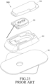
- a conventional sensing device 900 disclosed in U.S. Patent No. 7899511 includes a base 92, an adhesive base 91 that is adapted for adhering the base 92 onto a host's skin (not shown), a biosensor 93 that is mounted in the base 92, and a transducer 94 that is mounted to the base 92 and that is connected to the biosensor 93.
- the biosensor 93 is inserted beneath the host's skin for measuring a physiological signal corresponding to the blood glucose concentration level, and the transducer 94 receives the physiological signal from the biosensor 93 and forwards the physiological signal to an external device (not shown).
- the biosensor 93 includes a fixed seat 931, an elongated sensing member 932 that is fixedly mounted to the fixed seat 931, and two contactor heads 933 that are fixedly mounted to the fixed seat 931 and that are in contact with the sensing member 932.
- contact points (not shown) at a bottom end of the transducer 94 are to be in direct contact with the contactor heads 933 for enabling electric connection between the transducer 94 and the sensing member 932.
- the thickness of each of the contactor heads 933 (length in the coupling direction) cannot be smaller than the distance between the transducer 94 and the sensing member 932. As such, minimum thickness restriction to the contactor heads 933 made it difficult to reduce the overall thickness of sensing device 900.
- the contactor heads 933 may not be able to properly enable electric connection between the biosensor 93 and the transducer 94 due to manufacturing errors, such as misalignment of the contactor heads 933, or the contactor heads 933 having the thickness different from the distance between the transducer 94 and the sensing member 932.
- an object of the disclosure is to provide a physiological signal monitoring device that can alleviate the drawbacks of the prior art.
- the physiological signal monitoring device is for sensing a physiological signal in an analyte of a host, and includes a sensing member and a transmitter.
- the sensing member includes a signal sensing end adapted to be inserted underneath a skin of the host to sense the physiological signal, and a signal output end for outputting the physiological signal.
- the transmitter is connected to the sensing member for receiving, processing and transmitting the physiological signal, and includes a circuit board and a connecting port.
- the circuit board has a plurality of electrical contacts.
- the connecting port is connected to the circuit board and has a socket which is communicated to the circuit board, and a plurality of conducting springs which are received within the connecting port.
- the conducting springs are disposed at two opposite sides of the socket.
- the sensing member is removably inserted into the socket.
- Each of the conducting springs has one side electrically connected to a respective one of the electrical contacts of the circuit board and another side electrically connected to the signal output end of the sensing member for electric connection between the respective one of the electrical contacts and the signal output end.
- Each of the conducting springs is frictionally rotated by the sensing member during insertion of the sensing member into the socket and removal of the sensing member from the socket.
- a first embodiment of the physiological signal monitoring device is adapted to be mounted to a skin surface of a host (not shown), and is adapted for measuring at least one analyte of the host and for sending a corresponding type of physiological signal.
- the physiological signal monitoring device is for measuring the blood glucose concentration in the interstitial fluid (ISF) of the host, and is meant to be mounted to the skin surface for two weeks, but is not restricted to such.
- ISF interstitial fluid
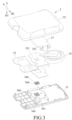
- the physiological signal monitoring device includes a base 1 that is adapted to be mounted to the skin surface of the host, a biosensor 2 that is mounted to the base 1 and that is adapted to be partially inserted underneath the skin surface of the host, and a transmitter 3 that covers and is removably coupled to the base 1 in a direction of a first axis (D1) and that is connected to the biosensor 2.
- the biosensor 2 is adapted for measuring at least one analyte of the host and for sending a corresponding physiological signal to the transmitter 3, while the transmitter 3 receives, processes, and outputs the physiological signal to an external device (not shown) for monitoring purposes.
- the transmitter 3 is permitted to be separated from the biosensor 2 and the base 1 to be reused with a new set of the base 1 and biosensor 2.
- the base 1 includes a base body 11, and an adhesive pad 16 that is mounted to a bottom surface 116 (see FIG. 6 ) of the base body 11 and that is permitted for attaching the base body 11 to the skin surface of the host.
- the biosensor 2 includes a fixed seat 21 that is mounted to the base body 11, and a sensing member 22 that is mounted to the fixed seat 21 and that extends through the base body 11. The fixed seat 21 is mounted between the transmitter 3 and the base 1 when the transmitter 3 is coupled to the base 1.
- the fixed seat 21 has a bottom surface 211 and a top surface 212.
- the sensing member 22 has a signal sensing end 222 that is adapted to be inserted underneath the skin surface of the host for measuring the physiological signal of the host, and a signal output end 221 that is adapted to output the physiological signal received from the signal sensing end 222.
- the signal sensing end 222 protrudes from the bottom surface 211 of the fixed seat 21, and the signal output end 221 protrudes from the top surface 212 of the fixed seat 21.
- the sensing member 22 includes a base board 225, a plurality of electrodes 226 mounted to a surface of the base board 225, and an analyte sensing layer (not shown) that covers the electrodes 226 and the surface of the base board 225.
- the analyte sensing layer is provided for reacting with the at least one analyte of the host, and the electrodes 226 includes signal receiving electrodes that detect outcome of the reaction, and signal sending electrodes that generate an electric signal indicating the outcome of the reaction.
- the electric signal is the physiological signal that indicates glucose levels in the interstitial fluid. Specific roles of the electrodes 226 will be elaborated later.
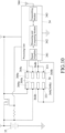
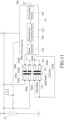
- the transmitter 3 includes a bottom casing 31 that is proximate to the base body 11, a top casing 32 that is mounted to the bottom casing 31 to define an inner space 30, a circuit board 33 that is disposed in the inner space 30, a processing unit 34 (see FIGS. 10 and 11 ) that is mounted to the circuit board 33, a battery 35 that is disposed in the inner space 30, and a connecting port 36 that is connected to a bottom surface of the circuit board 33 and that extends outwardly from the inner space 30 toward the base body 11.
- the circuit board 33 is permitted to be printed circuit board (PCB) or flexible print circuit (FPC), and is fixedly positioned to the bottom casing 31 via a supporting member 37, which may be made of a metal plate.
- the circuit board 33 has a plurality of electrical contacts 331 that correspond in position to the connecting port 36. In this embodiment, the number of the electrical contacts 331 is eight.
- the processing unit 34 is provided for receiving, processing, and sending the physiological signal, and is connected to the electrical contacts 331.
- the battery 35 is connected to the electrical contacts 331 of the circuit board 33.
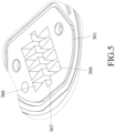
- the connecting port 36 includes a port casing 361 that is mounted to a bottom surface of the circuit board 33 and that extends downwardly toward a bottom surface 311 of the bottom casing 31 in the direction of the first axis (D1), and a plurality of spaced-apart conducting members 364 that are received within the port casing 361.
- the number of the conducting members 364 is eight.
- the port casing 361 is formed with a plurality of grooves 366 open toward the circuit board 33 and respectively receiving the conducting members 364 therein, and a socket 367 that extends toward the base body 11 in the direction of the first axis (D1) and that is communicated to the grooves 366.
- the conducting members 364 are respectively and rotatably received within the grooves 366.
- the socket 367 is provided to hold the signal output end 221 of the sensing member 22.
- a cross section of an outer periphery of the grooves 336 perpendicular to the first axis (D1) is substantially dovetail-shaped, and each of the grooves 336 tapers toward the socket 367 for preventing each of the conducting members 364 from escaping the respective one of the grooves 336.
- the conducting members 364 are elastic, and are disposed at two opposite sides of the socket 367.
- the conducting members 364 are conducting coil springs.
- Each of the conducting members 364 contacts with the circuit board 33 at one side along with a first direction, and contacts with the sensing member 22 at another side along a second direction wherein the first direction is nonparallel to the second direction. Therefore, the electric connection between the electrical contacts 331 of the circuit board 33 and the signal output end 221 of the sensing member 22 is provide when the sensing member 22 is inserted into the socket 367.
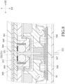
- each of the conducting members 364 has one side that is in contact with (and electrically connected to) a respective one of the electrical contacts 331 of the circuit board 33 in the direction of the first axis (D1) (i.e., the first direction) and another side that is in contact with (and electrically connected to) the electrodes 226 on the signal output end 221 of the sensing member 22 in a direction of a second axis (D2) (i.e., the second direction) for positioning the sensing member 22 when it is inserted into the socket 367 and for enabling electric connection between the electrical contacts 331 of the circuit board 33 and the signal output end 221 of the sensing member 22.
- D1 first axis
- D2 second axis
- the first and second axes (D1, D2) are substantially perpendicular to each other, but may not be restricted as such in other embodiments.
- the conducting coil springs have high degrees of freedom such that each of the conducting members 364 is rotated relative to the grooves 366 during insertion of the sensing member 22 into the socket 367 and removal of the sensing member 22 from the socket 367 along the first axis (D1), thereby reducing friction between the socket 367 and the sensing member 22 and facilitating the reuse of the transmitter 3.
- each of the conducting members 364 has one end welded to the port casing 361 so that one end of each of the conducting members 364 is fixed on the respective one of the grooves 366.
- the conducting members 364 are conducting coil springs
- each of the conducting members 364 has the following properties: the wire diameter thereof is smaller than 1 millimeter (mm), preferably 0.1 mm; the outer diameter thereof ranges from 0.5 mm to 1.8 mm, preferably 1.1 mm; the free length thereof ranges from 0.2 mm to 0.8 mm, preferably 0.44 mm to 0.56 mm.
- Each of the conducting members 364 has a helical portion 365a with two to six turns (three turns in this embodiment), thereby providing multi-point contacts with the respective one of the electrical contacts 331 of the circuit board 33 and the signal output end 221 of the sensing member 22.
- parameters such as the wire diameter and the number of turns of each of the conducting members 364 are designed in consideration to the elasticity of the conducting members 364, and the outer diameter and the free length of each of the conducting members 364 are designed in such a way that each of the conducting members 364 is slightly larger than a space of the respective one of the grooves 366, so that the conducting members 364 are in stable contact with the electrical contacts 331 of the circuit board 33 and the electrodes 226 on the signal output end 221 of the sensing member 22(see FIGS. 2 and 11 ).
- the conducting members 364 of the connecting port 36 which were originally conductive coil springs in the first embodiment, are steel balls or steel rings (i.e., rigid components) instead.
- the connecting port 36 further includes a plurality of elastic members 369, each of which is mounted in the respective one of the grooves 366 and is mounted between the port casing 361 and a respective one of the conducting members 364.
- the elastic members 369 are made of elastic materials such as rubber, and each of the conducting members 364 has one side contacted with the respective elastic member 369 and another side contacted with the electrodes 226 of the the signal output end 221 along an axis parallel to the second axis (D2).
- the conducting members 364 in this modification functions similarly to that of the first embodiment: enabling electric connection between the electrical contacts 331 and the signal output end 221, and being frictionally moved by the sensing member 22 to rotate in the grooves 366.
- the elastic members 369 ensure that the conducting members 364 are in stable contact with the sensing member 22 and the circuit board 33 along the directions parallel to the first axis (D1) and the second axis (D2) respectively.
- the conducting members 364 are conducting coil strings, each of which has an extended section 365b that extends along an inner surface of the port casing 361 toward the circuit board 33, and that is connected to the respective one of the electrical contacts 331 in the direction of the first axis (D1).
- the processing unit 34 receives the electric signal from the sensing member 22 and sends a corresponding physiological signal.
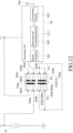
- the processing unit 34 includes a signal amplifier 341 receiving and amplifying the electric signal, a measuring and computing module 342 that converts the amplified electric signal sequentially into a physiological signal corresponding to the glucose level, and a transmitting module 343 that sends the physiological digital signal to an external device (not shown) via an antenna 344.
- the abovementioned physiological signal corresponding to the glucose level is electric current.
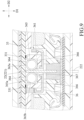
- the conducting members 364 are conducting coil springs and include two power-supplying conducting members 364a, four sensing conducting members 364b, and two transmitting conducting members 364c.
- the electrodes 226 of the sensing member 22 are in contact with the conducting members 364 to be respectively and electrically connected to the electrical contacts 331 of the circuit board 33 for the purposes of supplying power, sensing and transmitting data.
- the power-supplying conducting members 364a and the electrodes 226 cooperatively form a switch.
- the sensing conducting members 364b are connected to the processing unit 34.
- the transmitting conducting members 364c are connected to the processing unit 34 as well, and transmit data to the external device via the transmitting module 343 and the antenna 344.
- type of data transmission may be wireless transmission (Bluetooth, Wifi, NFC), but may be wired transmission (USB cable) in other embodiments.
- the number of the electrodes 226 of the sensing member 22 is five.
- the electrodes 226 include a working electrode 226a, a reference electrode 226b, a power-supplying electrode 226e, and two electrical contact sections 226d.
- the switch formed by the conducting members 364a is in an open circuit state, so that the battery 35 is in a non-power supplying state.
- the power-supplying electrode 226e of the sensing member 22 is in contact with the power-supplying conducting members 364a to be electrically connected with the electrical contacts 331 of the circuit board 33, such that the switch is in a closed circuit state and the battery 35 is switched to a power supplying state for supplying power to the sensing member 22 and the processing unit 34 for performing measurement of the analyte.
- each of the working and reference electrode 226a, 226b is in contact with corresponding two of the sensing conducting members 364b to be electrically connected to the electrical contacts 331 of the circuit board 33, such that the processing unit 34 receives, processes, and sends the physiological signal to the external device.
- the electrical contact sections 226d are permitted to be respectively and electrically connected to the transmitting conducting members 364c. In this embodiment, the electrical contact sections 226d has signal receiving and signal sending electrodes.
- a circuit layout of the transmitter 3 can be modified according to the various requirement of the product.
- the sensing member 22 begins measurement of the physiological signal of the host without power control by the processing unit 34 when the sensing member 22 is inserted into the socket 367.
- the circuit concerning to the power supply can be rearranged in other embodiments, so there is no more detailed description herein.
- the socket 367 of the connecting port 36 is further adapted for additional transmission device (not shown) or charging device (not shown) to be inserted thereinto.
- additional transmission device not shown
- charging device not shown
- the socket 367 of the connecting port 36 is further adapted for additional transmission device (not shown) or charging device (not shown) to be inserted thereinto.
- a connector (or an electrode) of the additional transmission device may be inserted into the socket 367 to provide electric connection and data transmission between the processing unit 34 and the additional transmission device through the transmitting conducting members 364c.
- the transmitting conducting members 364c are permitted to be electrically connected to the additional transmission device for exchanging data (default data or calibration data) before the transmitter 3 is connected to the biosensor 2 and the base 1.
- the charging device may be inserted into the socket 367 to recharge the transmitter 3 through the power-supplying conducting members 364a, which electrically interconnect the electrical contacts 331 of the circuit board 33 and the charging device.
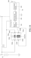
- the electrodes 226 of the sensing member 22 include a working electrode 226a, a counter electrode 226f, a power-supplying electrode 226e, and two electrical contact sections 226d, and the number of the conducting members 364 of the transmitter 3 is six.
- the conducting members 364 are conducting coil springs and include two power-supplying conducting members 364a, two sensing conducting members 364b, and two transmitting conducting members 364c.
- the power-supplying electrode 226e of the sensing member 22 is in contact with the power-supplying conducting members 364a to be electrically connected with the electrical contacts 331 of the circuit board 33.
- each of the working and counter electrode 226a, 226f is in contact with a respective one of the sensing conducting members 364b to be electrically connected to the electrical contacts 331 of the circuit board 33, such that the processing unit 34 receives, processes, and sends the physiological signal to the external device.
- the electrical contact sections 226d are permitted to be respectively and electrically connected to the transmitting conducting members 364c.
- the electrodes 226 of the sensing member 22 include a working electrode 226a, a counter electrode 226f, and two power-supplying electrodes 226e, and the number of the conducting members 364 of the transmitter 3 is four.
- the conducting members 364 are conducting coil springs and include two power-supplying conducting members 364a and two sensing conducting members 364b.
- each of the working and counter electrode 226a, 226f is in contact with a respective one of the sensing conducting members 364b to be electrically connected to the electrical contacts 331 of the circuit board 33, such that the processing unit 34 receives, processes, and sends the physiological signal to the external device.
- the electrical contacts 331 of the circuit board 33 and the electrodes 226 of the sensing member 22 are able to be electrically connected to activate the processing unit 34.
- the conducting coil springs in the abovementioned modifications may be conducting components of other forms.
- the transmitter 3 is coupled to the biosensor 2 assembled on the base 1 wherein the base 1 is attached on the host skin. Accordingly, the sensing member 22 of the biosensor 2 is inserted into the socket 367 of the transmitter 3 for the measurement of the analyte.
- the first embodiment of the physiological signal monitoring device provides the following benefits:
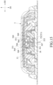
- FIGS. 15 and 16 illustrate a second embodiment of the physiological signal monitoring device wherein the difference between the first embodiment and the second embodiment is described as follows.
- the port casing 361 of the connecting port 36 has a plurality of slanted surfaces 368 respectively disposed in the grooves 366 and facing the circuit board 33 and the sensing member 22. Therefore, the conducting members 364 are forced against the circuit board 33 and the sensing member 22 with force vector provided by the slanted surfaces 368 to ensure the contact therebetween and enhance the mobility of the conducting members 364. Moreover, the conducting members 364 could return to the predetermined position after the removal of the sensing member 22 from the socket 367 because of the slanted surfaces 368 such that the contact problem resulting in electric disconnection between the conducting member 364 and the sensing member 22 could be solved. In other embodiments, the conducting members 364 could be modified as hard components(ex. steel ball or steel ring) with the elastic members 369 configured between the conducting members 364 and the slanted surfaces 368.
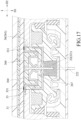
- FIG. 17 illustrates a third embodiment of the physiological signal monitoring device wherein the difference between the first embodiment and the third embodiment is described as follows.
- each of the conducting members 364 of the connecting port 36 is a leaf spring with one end contacted with the corresponding electrical contact 331 of the circuit board 33 along the first axis (D1) and another end contacted with the electrodes 226 of the sensing member 22 along the second axis (D2). Accordingly, the sensing member 22 is stably held within the socket 367 by the leaf springs 364 to provide reliable electric connection and signal transmission between the circuit board 33 and the sensing member 22.
- FIG. 18 illustrates a fourth embodiment of the physiological signal monitoring device wherein the difference between the first embodiment and the fourth embodiment is described as follows.
- the conducting members 364 are conducting coil springs.
- the connecting port 36 further includes a plurality of metal plates 370 respectively connected to the electrical contacts 331.
- the metal plates 370 are welded to the electrical contacts 331 via surface mount technology (SMT), and extended toward the grooves 366 to be disposed between the port casing 361 and the conducting members 364. Therefore, each of the conducting members 364 coaxially contacted with a respective one of the metal plates 370 and the electrodes 226 of the sensing member 22 along an axis parallel to the second axis (D2) to provide reliable electric connection between the circuit board 33 and the sensing member 22.
- SMT surface mount technology
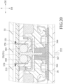
- FIGS. 19 and 20 illustrate other modifications of the fourth embodiment, in which the conducting members 364 are steel balls or steel rings instead wherein the metal plates 370 are welded to the electrical contacts 331 via surface mount technology (SMT) shown as FIG. 19 or dual in-line package (DIP) shown as FIG. 20 .
- SMT surface mount technology
- DIP dual in-line package
- the conducting members 364 of the connecting port 36 are disposed at two opposite sides of the socket 367.
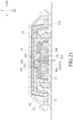
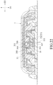
- the conducting members 364 of the connecting port 36 can be disposed at single side of the socket 367 instead, such that only single side of the sensing member 22 is abutted against the conducting members 364. Referring to FIGS. 21 and 22 , the sensing member 22 is stably held within the socket 367 by the elastic conducting members 364 and the port casing 361 to provide reliable electric connection between the circuit board 33 and the sensing member 22.
- the conducting members 364 are lateraly configured at the socket 367 to contact with the electrodes 226 of the sensing member 22 and the electrical contacts 331 of the circuit board 33 after the transmitter 3 is coupled to the biosensor 2, thereby providing the reliable electric connection therebetween and holding of the sensing member 22. Moreover, the conducting members 364 are rotated relative to the grooves 366 during insertion or removal of the sensing member 22 from the socket 367 to reduce friction resistance between conducting members 364 and the sensing member 22 and facilitate the reuse of the transmitter 3.
- the conducting members 364 can be conducting coil springs, steel balls/rings with the elastic members 369 or metal plates 370 to provide bidirectional or coaxial connection between the sensing member 22 and the circuir board 33. Therefore, the electrodes 226 of various functions are electrically connected with the electrical contacts 331 of single connecting port 36 to activate the power supply, signal sensing and date transmission.
Landscapes
- Health & Medical Sciences (AREA)
- Life Sciences & Earth Sciences (AREA)
- Physics & Mathematics (AREA)
- Engineering & Computer Science (AREA)
- Medical Informatics (AREA)
- Animal Behavior & Ethology (AREA)
- Veterinary Medicine (AREA)
- Biophysics (AREA)
- Pathology (AREA)
- Public Health (AREA)
- Biomedical Technology (AREA)
- Heart & Thoracic Surgery (AREA)
- General Health & Medical Sciences (AREA)
- Molecular Biology (AREA)
- Surgery (AREA)
- Optics & Photonics (AREA)
- Computer Networks & Wireless Communication (AREA)
- Hematology (AREA)
- Emergency Medicine (AREA)
- Chemical & Material Sciences (AREA)
- Chemical Kinetics & Catalysis (AREA)
- General Chemical & Material Sciences (AREA)
- Microelectronics & Electronic Packaging (AREA)
- Measuring And Recording Apparatus For Diagnosis (AREA)
- Measurement Of The Respiration, Hearing Ability, Form, And Blood Characteristics Of Living Organisms (AREA)
Claims (20)
- Eine Physiologisches-Signal-Überwachungsvorrichtung zum Erfassen eines physiologischen Signals in einem Analyten eines Wirts, die folgende Merkmale aufweist:
ein Erfassungselement (22), das Folgendes aufweist:ein Signalerfassungsende (222), das dazu angepasst ist, unter eine Haut des Wirts eingeführt zu werden, um das physiologische Signal zu erfassen, undein Signalausgabeende (221) zum Ausgeben des physiologischen Signals; undeinen Sender (3), der mit dem Erfassungselement (22) verbunden ist, um das physiologische Signal zu empfangen, zu verarbeiten und zu senden, wobei die Physiologisches-Signal-Überwachungsvorrichtung dadurch gekennzeichnet ist, dass der Sender (3) Folgendes umfasst:eine Leiterplatte (33), die eine Vielzahl von elektrischen Kontakten (331) aufweist, undeinen Verbindungsanschluss (36), der mit der Leiterplatte (33) verbunden ist und eine Buchse (367) , die mit der Leiterplatte (33) in Verbindung steht, und eine Vielzahl von leitenden Federn (364)aufweist, die in dem Verbindungsanschluss (36) aufgenommen sind;wobei das Erfassungselement (22) entfernbar in die Buchse (367) eingeführt ist;wobei jede der leitenden Federn (364) eine Seite, die elektrisch mit einem jeweiligen der elektrischen Kontakte (331) der Leiterplatte (33) verbunden ist, und eine andere Seite, die elektrisch mit dem Signalausgabeende (221) des Erfassungselements (22) verbunden ist, zur elektrischen Verbindung zwischen dem jeweiligen der elektrischen Kontakte (331) und dem Signalausgabeende (221) aufweist; und wobei jede der leitenden Federn (364) während des Einführens des Erfassungselements (22) in die Buchse (367) und des Entfernens des Erfassungselements (22) aus der Buchse (367) durch das Erfassungselement (22) reibschlüssig gedreht wird. - Die Physiologisches-Signal-Überwachungsvorrichtung gemäß Anspruch 1, die dadurch gekennzeichnet ist, dass der Verbindungsanschluss (36) ferner ein Anschlussgehäuse (361) umfasst, das auf der Leiterplatte (33) montiert ist und mit der Buchse (367) ausgebildet ist, wobei das Anschlussgehäuse (361) eine Vielzahl von schrägen Oberflächen (368) aufweist, die der Leiterplatte (33) und dem Erfassungselement (22) zugewandt sind, wodurch die leitenden Federn (364) gegen die Leiterplatte (33) und die Erfassungselemente (22) gedrückt werden.
- Die Physiologisches-Signal-Überwachungsvorrichtung gemäß Anspruch 1, die dadurch gekennzeichnet ist, dass der Verbindungsanschluss (36) ferner ein Anschlussgehäuse (361), das auf der Leiterplatte (33) montiert ist und mit der Buchse (367) ausgebildet ist, und eine Vielzahl von Nuten (366) umfasst, die mit der Buchse (367) in Verbindung stehen, um die leitenden Federn (364) darin aufzunehmen.
- Die Physiologisches-Signal-Überwachungsvorrichtung gemäß Anspruch 3, die dadurch gekennzeichnet ist, dass sich jede der Nuten (366) des Verbindungsanschlusses (36) zu der Buchse (367) hin verjüngt.
- Die Physiologisches-Signal-Überwachungsvorrichtung gemäß Anspruch 3, die dadurch gekennzeichnet ist, dass die leitenden Federn (364) des Verbindungsanschlusses (36) an einer Seite der Buchse (367) angeordnet sind.
- Die Physiologisches-Signal-Überwachungsvorrichtung gemäß Anspruch 3, die dadurch gekennzeichnet ist, dass die leitenden Federn (364) des Verbindungsanschlusses (36) an zwei gegenüberliegenden Seiten der Buchse (367) angeordnet sind.
- Die Physiologisches-Signal-Überwachungsvorrichtung gemäß Anspruch 3, die dadurch gekennzeichnet ist, dass jede der leitenden Federn (364) einen verlängerten Abschnitt (365b) aufweist, der sich entlang einer inneren Oberfläche des Anschlussgehäuses (361) zu der Leiterplatte (33) hin erstreckt und mit dem jeweiligen der elektrischen Kontakte (331) verbunden ist.
- Die Physiologisches-Signal-Überwachungsvorrichtung gemäß Anspruch 3, die dadurch gekennzeichnet ist, dass jede der leitenden Federn (364) ein Ende aufweist, das an einer jeweiligen der Nuten (366) befestigt ist.
- Die Physiologisches-Signal-Überwachungsvorrichtung gemäß Anspruch 1, die dadurch gekennzeichnet ist, dass jede der leitenden Federn (364) die eine Seite, die mit dem jeweiligen der elektrischen Kontakte (331) entlang einer Richtung einer ersten Achse (D1) in Kontakt ist, und die andere Seite, die mit dem Signalausgabeende (221) entlang einer Richtung einer zweiten Achse (D2) in Kontakt ist, aufweist.
- Die Physiologisches-Signal-Überwachungsvorrichtung gemäß Anspruch 1, die dadurch gekennzeichnet ist, dass der Verbindungsanschluss (36) ferner eine Vielzahl von Metallplatten (370) umfasst, die jeweils mit den elektrischen Kontakten (331) verbunden sind, um die leitenden Federn (364) gegen das Erfassungselement (22) zu drücken, wobei jede der leitenden Federn (364) koaxial mit einer jeweiligen der Metallplatten (370) und dem Signalausgabeende (221) des Erfassungselements (22) in Kontakt ist.
- Die Physiologisches-Signal-Überwachungsvorrichtung gemäß Anspruch 1, die dadurch gekennzeichnet ist, dass:das Erfassungselement (22) eine Vielzahl von Elektroden (226) in Kontakt mit den leitenden Federn (364) aufweist, die eine Stromversorgungselektrode (226e) und eine Elektrode umfassen, die aus der Gruppe ausgewählt ist, die aus einer Arbeitselektrode (226a), einer Referenzelektrode (226b) und einer Gegenelektrode (226f) und Kombinationen davon besteht; unddie leitenden Federn (364) leitende Erfassungsfedern (364b) und leitende Stromversorgungsfedern (364a) umfassen.
- Die Physiologisches-Signal-Überwachungsvorrichtung gemäß Anspruch 11, die dadurch gekennzeichnet ist, dass die leitenden Federn (364) ferner eine Vielzahl von leitenden Übertragungsfedern (364c) umfassen.
- Die Physiologisches-Signal-Überwachungsvorrichtung gemäß Anspruch 11, die dadurch gekennzeichnet ist, dass:der Sender (3) ferner eine Batterie (35) umfasst, die mit den elektrischen Kontakten (331) durch die leitenden Stromversorgungsfedern (364a) verbunden ist, wobei die Elektroden (226) und die leitenden Stromversorgungsfedern (364a) einen Schalter bilden;der Schalter in einem Zustand mit offenem Stromkreis ist und die Batterie (35) in einem Zustand ohne Stromversorgung ist, wenn das Erfassungselement (22) nicht in die Buchse (367) des Verbindungsanschlusses (36) eingeführt ist; undder Schalter in einem Zustand mit geschlossenem Stromkreis ist und die Batterie (35) in einem Stromversorgungszustand ist, wenn das Erfassungselement (22) in die Buchse (367) des Verbindungsanschlusses (36) eingeführt ist, um eine elektrische Verbindung zwischen der Stromversorgungselektrode (226e) des Erfassungselements (22) und den leitenden Stromversorgungsfedern (364a) bereitzustellen.
- Die Physiologisches-Signal-Überwachungsvorrichtung gemäß Anspruch 11, die dadurch gekennzeichnet ist, dass:der Sender (3) ferner eine Verarbeitungseinheit (34) umfasst, die mit den elektrischen Kontakten (331) verbunden ist; undmindestens eine der Arbeits-, Referenz- und Gegenelektroden (226a, 226b, 226f) in Kontakt mit den leitenden Erfassungsfedern (364b) ist, um das physiologische Signal an die Verarbeitungseinheit (34) zu übertragen, wenn das Erfassungselement (22) in die Buchse (367) des Verbindungsanschlusses (36) eingeführt ist.
- Die Physiologisches-Signal-Überwachungsvorrichtung gemäß Anspruch 12, die dadurch gekennzeichnet ist, dass:der Sender (3) ferner eine Verarbeitungseinheit (34) umfasst, die mit den elektrischen Kontakten (331) verbunden ist; unddie Buchse (367) des Verbindungsanschlusses (36) ferner dazu angepasst ist, dass eine zusätzliche Übertragungsvorrichtung darin eingeführt wird, um eine elektrische Verbindung und Datenübertragung zwischen der Verarbeitungseinheit (34) und der zusätzlichen Übertragungsvorrichtung durch die leitenden Übertragungsfedern (364c) bereitzustellen.
- Die Physiologisches-Signal-Überwachungsvorrichtung gemäß Anspruch 1, die dadurch gekennzeichnet ist, dass jede der leitenden Federn (364) einen schraubenförmigen Abschnitt (365a) mit einer Vielzahl von Windungen umfasst, wodurch Mehrpunktkontakte mit dem jeweiligen der elektrischen Kontakte (331) der Leiterplatte (33) und dem Signalausgabeende (221) des Erfassungselements (22) bereitgestellt werden.
- Die Physiologisches-Signal-Überwachungsvorrichtung gemäß Anspruch 1, die dadurch gekennzeichnet ist, dass die leitenden Federn (364) Blattfedern sind.
- Die Physiologisches-Signal-Überwachungsvorrichtung gemäß Anspruch 1, die dadurch gekennzeichnet ist, dass das Erfassungselement (22) in die Buchse (367) entlang einer ersten Achse (D1) eingeführt ist und das Signalausgabeende (221) des Erfassungselements (22) elektrisch mit jedem der leitenden Elemente (364) entlang einer zweiten Achse (D2) verbunden ist.
- Die Physiologisches-Signal-Überwachungsvorrichtung gemäß Anspruch 1, die dadurch gekennzeichnet ist, dass die Physiologisches-Signal-Überwachungsvorrichtung ferner einen festen Sitz (21) aufweist, wobei das Erfassungselement (22) innerhalb des festen Sitzes (21) gehalten wird.
- Die Physiologisches-Signal-Überwachungsvorrichtung gemäß Anspruch 19, die dadurch gekennzeichnet ist, dass die Physiologisches-Signal-Überwachungsvorrichtung ferner eine Basis (1) aufweist, die lösbar mit dem Sender (3) gekoppelt ist, wobei der feste Sitz (21) zwischen dem Sender (3) und der Basis (1) montiert ist und das Signalerfassungsende (222) des Erfassungselements (22) von einer unteren Oberfläche (211) des festen Sitzes (21) vorsteht.
Applications Claiming Priority (4)
| Application Number | Priority Date | Filing Date | Title |
|---|---|---|---|
| US201962882140P | 2019-08-02 | 2019-08-02 | |
| TW109100852A TWI731545B (zh) | 2019-08-02 | 2020-01-10 | 生理訊號傳感裝置 |
| TW109100968A TWI735138B (zh) | 2019-08-02 | 2020-01-10 | 生理訊號傳感裝置 |
| TW109109245A TWI737224B (zh) | 2019-08-02 | 2020-03-19 | 生理訊號傳感裝置 |
Publications (3)
| Publication Number | Publication Date |
|---|---|
| EP3771407A1 EP3771407A1 (de) | 2021-02-03 |
| EP3771407B1 true EP3771407B1 (de) | 2024-10-23 |
| EP3771407C0 EP3771407C0 (de) | 2024-10-23 |
Family
ID=71899620
Family Applications (1)
| Application Number | Title | Priority Date | Filing Date |
|---|---|---|---|
| EP20188961.5A Active EP3771407B1 (de) | 2019-08-02 | 2020-07-31 | Vorrichtung zur überwachung physiologischer signale |
Country Status (7)
| Country | Link |
|---|---|
| US (1) | US11717198B2 (de) |
| EP (1) | EP3771407B1 (de) |
| JP (1) | JP7014865B2 (de) |
| KR (1) | KR102443001B1 (de) |
| AU (1) | AU2020213273B2 (de) |
| CA (1) | CA3088595C (de) |
| WO (1) | WO2021024128A1 (de) |
Families Citing this family (4)
| Publication number | Priority date | Publication date | Assignee | Title |
|---|---|---|---|---|
| CN115251910B (zh) * | 2021-04-29 | 2026-01-16 | 杭州微策生物技术股份有限公司 | 一种安全自锁助针器 |
| TWD226583S (zh) * | 2022-08-31 | 2023-07-21 | 華廣生技股份有限公司 | 生理訊號監測貼片 |
| TWD226582S (zh) * | 2022-08-31 | 2023-07-21 | 華廣生技股份有限公司 | 生理訊號監測貼片 |
| TWD226584S (zh) * | 2022-08-31 | 2023-07-21 | 華廣生技股份有限公司 | 生理訊號監測貼片 |
Family Cites Families (36)
| Publication number | Priority date | Publication date | Assignee | Title |
|---|---|---|---|---|
| US7899511B2 (en) | 2004-07-13 | 2011-03-01 | Dexcom, Inc. | Low oxygen in vivo analyte sensor |
| US8465425B2 (en) | 1998-04-30 | 2013-06-18 | Abbott Diabetes Care Inc. | Analyte monitoring device and methods of use |
| CA2360513C (en) | 1999-02-25 | 2004-11-16 | Minimed Inc. | Test plug and cable for a glucose monitor |
| US6749587B2 (en) * | 2001-02-22 | 2004-06-15 | Insulet Corporation | Modular infusion device and method |
| US7920906B2 (en) | 2005-03-10 | 2011-04-05 | Dexcom, Inc. | System and methods for processing analyte sensor data for sensor calibration |
| US8792955B2 (en) | 2004-05-03 | 2014-07-29 | Dexcom, Inc. | Transcutaneous analyte sensor |
| US8886272B2 (en) | 2004-07-13 | 2014-11-11 | Dexcom, Inc. | Analyte sensor |
| US8989833B2 (en) | 2004-07-13 | 2015-03-24 | Dexcom, Inc. | Transcutaneous analyte sensor |
| WO2008105768A1 (en) | 2007-03-01 | 2008-09-04 | Dexcom, Inc. | Analyte sensor |
| BRPI0909361A2 (pt) | 2008-03-17 | 2015-09-29 | Isense Corp | subconjunto sensor de analito e métodos e aparelhos para inserir um sensor de analito associado com o mesmo |
| TWI424832B (zh) | 2008-12-15 | 2014-02-01 | 波提亞斯數位康健公司 | 與身體有關的接收器及其方法 |
| JP5795584B2 (ja) | 2009-08-31 | 2015-10-14 | アボット ダイアベティス ケア インコーポレイテッドAbbott Diabetes Care Inc. | 医療用装置 |
| EP2513953B1 (de) | 2009-12-16 | 2017-10-18 | The Board of Trustees of the University of Illionis | Elektrophysiologie unter verwendung konformer elektronischer vorrichtungen |
| TWI439689B (zh) | 2010-09-23 | 2014-06-01 | 華廣生技股份有限公司 | Electrochemical test specimen |
| WO2012097879A1 (en) | 2011-01-21 | 2012-07-26 | St. Jude Medical Ab | Implantable device with improved surface characteristics |
| TWI569773B (zh) | 2011-05-26 | 2017-02-11 | 華廣生技股份有限公司 | 量測一生理參數的系統及方法 |
| TWI452997B (zh) | 2011-10-05 | 2014-09-21 | Univ Kun Shan | 具有奈米結構之射頻生醫感測晶片 |
| AU2012352560B2 (en) | 2011-12-11 | 2017-01-19 | Abbott Diabetes Care Inc. | Analyte sensor devices, connections, and methods |
| US20130267812A1 (en) | 2012-04-04 | 2013-10-10 | Dexcom, Inc. | Transcutaneous analyte sensors, applicators therefor, and associated methods |
| US20160045158A1 (en) | 2013-03-15 | 2016-02-18 | Prometheon Pharma, Llc | Devices, systems, and methods for transdermal delivery of compounds |
| CN104887242B (zh) | 2014-03-07 | 2018-08-28 | 上海移宇科技股份有限公司 | 分析物传感系统 |
| EP3171768B1 (de) | 2014-08-01 | 2020-09-16 | LifeLens Technologies, LLC | Modulare physiologische überwachungssysteme |
| CN105873514B (zh) * | 2014-10-27 | 2018-10-26 | 深圳市光聚通讯技术开发有限公司 | 动态血糖采集装置及主机 |
| WO2017004531A1 (en) | 2015-07-02 | 2017-01-05 | The Board Of Trustees Of The University Of Illinois | Fully implantable soft medical devices for interfacing with biological tissue |
| EP3364870B1 (de) | 2015-10-21 | 2022-09-07 | Neuspera Medical Inc. | Vorrichtungen und systeme zur stimulationstherapie |
| DE202016009211U1 (de) * | 2015-12-30 | 2024-04-08 | Dexcom, Inc. | Systeme für transkutane Analytsensoren |
| ES2961001T3 (es) | 2016-01-19 | 2024-03-07 | Hoffmann La Roche | Conjunto de sensor y procedimiento para detectar al menos un analito en un líquido corporal |
| SMT202400475T1 (it) | 2016-02-05 | 2025-01-14 | Hoffmann La Roche | Dispositivo medico per rilevare almeno un analita in un fluido corporeo |
| SG11201807715UA (en) | 2016-03-09 | 2018-10-30 | Peerbridge Health Inc | System and method for monitoring conditions of a subject based on wireless sensor data |
| US10765369B2 (en) | 2016-04-08 | 2020-09-08 | Medtronic Minimed, Inc. | Analyte sensor |
| US10420508B2 (en) * | 2016-04-08 | 2019-09-24 | Medtronic Minimed, Inc. | Sensor connections |
| WO2018222012A1 (ko) | 2017-06-02 | 2018-12-06 | 주식회사 아이센스 | 연속 혈당 측정기용 센서 어플리케이터 조립체 |
| JP6866508B2 (ja) * | 2017-06-02 | 2021-04-28 | アイセンス,インコーポレーテッド | 連続血糖測定器用センサーアプリケーター組立体 |
| WO2019081734A1 (en) | 2017-10-27 | 2019-05-02 | Roche Diabetes Care Gmbh | DEVICE AND METHOD FOR DETECTING AT LEAST ONE ANALYTE IN A BODY FLUID OF A USER |
| US11026751B2 (en) | 2017-12-28 | 2021-06-08 | Cilag Gmbh International | Display of alignment of staple cartridge to prior linear staple line |
| CN208926382U (zh) | 2018-03-29 | 2019-06-04 | 全康科技股份有限公司 | 经皮微针阵列贴布 |
-
2020
- 2020-07-31 US US16/944,830 patent/US11717198B2/en active Active
- 2020-07-31 EP EP20188961.5A patent/EP3771407B1/de active Active
- 2020-07-31 CA CA3088595A patent/CA3088595C/en active Active
- 2020-07-31 WO PCT/IB2020/057252 patent/WO2021024128A1/en not_active Ceased
- 2020-08-03 AU AU2020213273A patent/AU2020213273B2/en active Active
- 2020-08-03 KR KR1020200096692A patent/KR102443001B1/ko active Active
- 2020-08-03 JP JP2020131796A patent/JP7014865B2/ja active Active
Also Published As
| Publication number | Publication date |
|---|---|
| KR20210016304A (ko) | 2021-02-15 |
| JP7014865B2 (ja) | 2022-02-01 |
| EP3771407A1 (de) | 2021-02-03 |
| US20210030315A1 (en) | 2021-02-04 |
| CA3088595A1 (en) | 2021-02-02 |
| EP3771407C0 (de) | 2024-10-23 |
| AU2020213273A1 (en) | 2021-02-18 |
| US11717198B2 (en) | 2023-08-08 |
| AU2020213273B2 (en) | 2021-04-08 |
| JP2021023820A (ja) | 2021-02-22 |
| WO2021024128A1 (en) | 2021-02-11 |
| KR102443001B1 (ko) | 2022-09-13 |
| CA3088595C (en) | 2023-04-04 |
Similar Documents
| Publication | Publication Date | Title |
|---|---|---|
| EP3771417B1 (de) | Vorrichtung zur überwachung physiologischer signale | |
| EP3771428B1 (de) | Vorrichtung zur überwachung physiologischer signale | |
| EP3771407B1 (de) | Vorrichtung zur überwachung physiologischer signale | |
| TWI737223B (zh) | 生理訊號傳感裝置 | |
| US20230329603A1 (en) | Physiological signal monitoring device | |
| KR20050121472A (ko) | 생체신호 검출모듈, 다채널 커넥터 모듈 및 이를 포함한생체신호 검출장치 | |
| CN112294305B (zh) | 生理信号传感装置 | |
| JP7829918B2 (ja) | ウェアラブルデバイス | |
| JP5370069B2 (ja) | 充電装置用アタッチメントおよび充電装置 | |
| JP2016012246A (ja) | 電子機器 | |
| US20180151971A1 (en) | Internal and External Connector and Receptacle | |
| CA2676753A1 (en) | Measurement connector |
Legal Events
| Date | Code | Title | Description |
|---|---|---|---|
| PUAI | Public reference made under article 153(3) epc to a published international application that has entered the european phase |
Free format text: ORIGINAL CODE: 0009012 |
|
| STAA | Information on the status of an ep patent application or granted ep patent |
Free format text: STATUS: THE APPLICATION HAS BEEN PUBLISHED |
|
| AK | Designated contracting states |
Kind code of ref document: A1 Designated state(s): AL AT BE BG CH CY CZ DE DK EE ES FI FR GB GR HR HU IE IS IT LI LT LU LV MC MK MT NL NO PL PT RO RS SE SI SK SM TR |
|
| AX | Request for extension of the european patent |
Extension state: BA ME |
|
| STAA | Information on the status of an ep patent application or granted ep patent |
Free format text: STATUS: REQUEST FOR EXAMINATION WAS MADE |
|
| 17P | Request for examination filed |
Effective date: 20210803 |
|
| RBV | Designated contracting states (corrected) |
Designated state(s): AL AT BE BG CH CY CZ DE DK EE ES FI FR GB GR HR HU IE IS IT LI LT LU LV MC MK MT NL NO PL PT RO RS SE SI SK SM TR |
|
| GRAP | Despatch of communication of intention to grant a patent |
Free format text: ORIGINAL CODE: EPIDOSNIGR1 |
|
| STAA | Information on the status of an ep patent application or granted ep patent |
Free format text: STATUS: GRANT OF PATENT IS INTENDED |
|
| INTG | Intention to grant announced |
Effective date: 20240604 |
|
| GRAS | Grant fee paid |
Free format text: ORIGINAL CODE: EPIDOSNIGR3 |
|
| GRAA | (expected) grant |
Free format text: ORIGINAL CODE: 0009210 |
|
| STAA | Information on the status of an ep patent application or granted ep patent |
Free format text: STATUS: THE PATENT HAS BEEN GRANTED |
|
| AK | Designated contracting states |
Kind code of ref document: B1 Designated state(s): AL AT BE BG CH CY CZ DE DK EE ES FI FR GB GR HR HU IE IS IT LI LT LU LV MC MK MT NL NO PL PT RO RS SE SI SK SM TR |
|
| REG | Reference to a national code |
Ref country code: GB Ref legal event code: FG4D |
|
| REG | Reference to a national code |
Ref country code: CH Ref legal event code: EP |
|
| REG | Reference to a national code |
Ref country code: DE Ref legal event code: R096 Ref document number: 602020039797 Country of ref document: DE |
|
| REG | Reference to a national code |
Ref country code: IE Ref legal event code: FG4D |
|
| U01 | Request for unitary effect filed |
Effective date: 20241115 |
|
| U07 | Unitary effect registered |
Designated state(s): AT BE BG DE DK EE FI FR IT LT LU LV MT NL PT RO SE SI Effective date: 20241122 |
|
| PG25 | Lapsed in a contracting state [announced via postgrant information from national office to epo] |
Ref country code: IS Free format text: LAPSE BECAUSE OF FAILURE TO SUBMIT A TRANSLATION OF THE DESCRIPTION OR TO PAY THE FEE WITHIN THE PRESCRIBED TIME-LIMIT Effective date: 20250223 Ref country code: HR Free format text: LAPSE BECAUSE OF FAILURE TO SUBMIT A TRANSLATION OF THE DESCRIPTION OR TO PAY THE FEE WITHIN THE PRESCRIBED TIME-LIMIT Effective date: 20241023 |
|
| PG25 | Lapsed in a contracting state [announced via postgrant information from national office to epo] |
Ref country code: ES Free format text: LAPSE BECAUSE OF FAILURE TO SUBMIT A TRANSLATION OF THE DESCRIPTION OR TO PAY THE FEE WITHIN THE PRESCRIBED TIME-LIMIT Effective date: 20241023 |
|
| PG25 | Lapsed in a contracting state [announced via postgrant information from national office to epo] |
Ref country code: NO Free format text: LAPSE BECAUSE OF FAILURE TO SUBMIT A TRANSLATION OF THE DESCRIPTION OR TO PAY THE FEE WITHIN THE PRESCRIBED TIME-LIMIT Effective date: 20250123 |
|
| PG25 | Lapsed in a contracting state [announced via postgrant information from national office to epo] |
Ref country code: GR Free format text: LAPSE BECAUSE OF FAILURE TO SUBMIT A TRANSLATION OF THE DESCRIPTION OR TO PAY THE FEE WITHIN THE PRESCRIBED TIME-LIMIT Effective date: 20250124 |
|
| PG25 | Lapsed in a contracting state [announced via postgrant information from national office to epo] |
Ref country code: PL Free format text: LAPSE BECAUSE OF FAILURE TO SUBMIT A TRANSLATION OF THE DESCRIPTION OR TO PAY THE FEE WITHIN THE PRESCRIBED TIME-LIMIT Effective date: 20241023 |
|
| PG25 | Lapsed in a contracting state [announced via postgrant information from national office to epo] |
Ref country code: RS Free format text: LAPSE BECAUSE OF FAILURE TO SUBMIT A TRANSLATION OF THE DESCRIPTION OR TO PAY THE FEE WITHIN THE PRESCRIBED TIME-LIMIT Effective date: 20250123 |
|
| PG25 | Lapsed in a contracting state [announced via postgrant information from national office to epo] |
Ref country code: SM Free format text: LAPSE BECAUSE OF FAILURE TO SUBMIT A TRANSLATION OF THE DESCRIPTION OR TO PAY THE FEE WITHIN THE PRESCRIBED TIME-LIMIT Effective date: 20241023 |
|
| PG25 | Lapsed in a contracting state [announced via postgrant information from national office to epo] |
Ref country code: SK Free format text: LAPSE BECAUSE OF FAILURE TO SUBMIT A TRANSLATION OF THE DESCRIPTION OR TO PAY THE FEE WITHIN THE PRESCRIBED TIME-LIMIT Effective date: 20241023 |
|
| PG25 | Lapsed in a contracting state [announced via postgrant information from national office to epo] |
Ref country code: CZ Free format text: LAPSE BECAUSE OF FAILURE TO SUBMIT A TRANSLATION OF THE DESCRIPTION OR TO PAY THE FEE WITHIN THE PRESCRIBED TIME-LIMIT Effective date: 20241023 |
|
| U20 | Renewal fee for the european patent with unitary effect paid |
Year of fee payment: 6 Effective date: 20250707 |
|
| PLBE | No opposition filed within time limit |
Free format text: ORIGINAL CODE: 0009261 |
|
| STAA | Information on the status of an ep patent application or granted ep patent |
Free format text: STATUS: NO OPPOSITION FILED WITHIN TIME LIMIT |
|
| 26N | No opposition filed |
Effective date: 20250724 |
|
| PGFP | Annual fee paid to national office [announced via postgrant information from national office to epo] |
Ref country code: GB Payment date: 20250725 Year of fee payment: 6 |
|
| PGFP | Annual fee paid to national office [announced via postgrant information from national office to epo] |
Ref country code: CH Payment date: 20250801 Year of fee payment: 6 |
|
| PGFP | Annual fee paid to national office [announced via postgrant information from national office to epo] |
Ref country code: IE Payment date: 20250722 Year of fee payment: 6 |