EP3771428B1 - Dispositif de surveillance de signal physiologique - Google Patents
Dispositif de surveillance de signal physiologique Download PDFInfo
- Publication number
- EP3771428B1 EP3771428B1 EP20189221.3A EP20189221A EP3771428B1 EP 3771428 B1 EP3771428 B1 EP 3771428B1 EP 20189221 A EP20189221 A EP 20189221A EP 3771428 B1 EP3771428 B1 EP 3771428B1
- Authority
- EP
- European Patent Office
- Prior art keywords
- sensing member
- socket
- physiological signal
- monitoring device
- circuit board
- Prior art date
- Legal status (The legal status is an assumption and is not a legal conclusion. Google has not performed a legal analysis and makes no representation as to the accuracy of the status listed.)
- Active
Links
Images









Classifications
-
- A—HUMAN NECESSITIES
- A61—MEDICAL OR VETERINARY SCIENCE; HYGIENE
- A61B—DIAGNOSIS; SURGERY; IDENTIFICATION
- A61B5/00—Measuring for diagnostic purposes; Identification of persons
- A61B5/145—Measuring characteristics of blood in vivo, e.g. gas concentration or pH-value ; Measuring characteristics of body fluids or tissues, e.g. interstitial fluid or cerebral tissue
- A61B5/14532—Measuring characteristics of blood in vivo, e.g. gas concentration or pH-value ; Measuring characteristics of body fluids or tissues, e.g. interstitial fluid or cerebral tissue for measuring glucose, e.g. by tissue impedance measurement
-
- A—HUMAN NECESSITIES
- A61—MEDICAL OR VETERINARY SCIENCE; HYGIENE
- A61B—DIAGNOSIS; SURGERY; IDENTIFICATION
- A61B5/00—Measuring for diagnostic purposes; Identification of persons
- A61B5/0002—Remote monitoring of patients using telemetry, e.g. transmission of vital signals via a communication network
- A61B5/0004—Remote monitoring of patients using telemetry, e.g. transmission of vital signals via a communication network characterised by the type of physiological signal transmitted
-
- A—HUMAN NECESSITIES
- A61—MEDICAL OR VETERINARY SCIENCE; HYGIENE
- A61B—DIAGNOSIS; SURGERY; IDENTIFICATION
- A61B5/00—Measuring for diagnostic purposes; Identification of persons
- A61B5/145—Measuring characteristics of blood in vivo, e.g. gas concentration or pH-value ; Measuring characteristics of body fluids or tissues, e.g. interstitial fluid or cerebral tissue
- A61B5/14503—Measuring characteristics of blood in vivo, e.g. gas concentration or pH-value ; Measuring characteristics of body fluids or tissues, e.g. interstitial fluid or cerebral tissue invasive, e.g. introduced into the body by a catheter or needle or using implanted sensors
-
- A—HUMAN NECESSITIES
- A61—MEDICAL OR VETERINARY SCIENCE; HYGIENE
- A61B—DIAGNOSIS; SURGERY; IDENTIFICATION
- A61B5/00—Measuring for diagnostic purposes; Identification of persons
- A61B5/68—Arrangements of detecting, measuring or recording means, e.g. sensors, in relation to patient
- A61B5/6846—Arrangements of detecting, measuring or recording means, e.g. sensors, in relation to patient specially adapted to be brought in contact with an internal body part, i.e. invasive
- A61B5/6879—Means for maintaining contact with the body
- A61B5/688—Means for maintaining contact with the body using adhesives
-
- A—HUMAN NECESSITIES
- A61—MEDICAL OR VETERINARY SCIENCE; HYGIENE
- A61B—DIAGNOSIS; SURGERY; IDENTIFICATION
- A61B2560/00—Constructional details of operational features of apparatus; Accessories for medical measuring apparatus
- A61B2560/04—Constructional details of apparatus
- A61B2560/0443—Modular apparatus
- A61B2560/045—Modular apparatus with a separable interface unit, e.g. for communication
-
- A—HUMAN NECESSITIES
- A61—MEDICAL OR VETERINARY SCIENCE; HYGIENE
- A61B—DIAGNOSIS; SURGERY; IDENTIFICATION
- A61B2562/00—Details of sensors; Constructional details of sensor housings or probes; Accessories for sensors
- A61B2562/16—Details of sensor housings or probes; Details of structural supports for sensors
- A61B2562/166—Details of sensor housings or probes; Details of structural supports for sensors the sensor is mounted on a specially adapted printed circuit board
-
- A—HUMAN NECESSITIES
- A61—MEDICAL OR VETERINARY SCIENCE; HYGIENE
- A61B—DIAGNOSIS; SURGERY; IDENTIFICATION
- A61B2562/00—Details of sensors; Constructional details of sensor housings or probes; Accessories for sensors
- A61B2562/22—Arrangements of medical sensors with cables or leads; Connectors or couplings specifically adapted for medical sensors
- A61B2562/225—Connectors or couplings
- A61B2562/226—Connectors or couplings comprising means for identifying the connector, e.g. to prevent incorrect connection to socket
-
- A—HUMAN NECESSITIES
- A61—MEDICAL OR VETERINARY SCIENCE; HYGIENE
- A61B—DIAGNOSIS; SURGERY; IDENTIFICATION
- A61B2562/00—Details of sensors; Constructional details of sensor housings or probes; Accessories for sensors
- A61B2562/22—Arrangements of medical sensors with cables or leads; Connectors or couplings specifically adapted for medical sensors
- A61B2562/225—Connectors or couplings
- A61B2562/227—Sensors with electrical connectors
-
- A—HUMAN NECESSITIES
- A61—MEDICAL OR VETERINARY SCIENCE; HYGIENE
- A61B—DIAGNOSIS; SURGERY; IDENTIFICATION
- A61B5/00—Measuring for diagnostic purposes; Identification of persons
- A61B5/145—Measuring characteristics of blood in vivo, e.g. gas concentration or pH-value ; Measuring characteristics of body fluids or tissues, e.g. interstitial fluid or cerebral tissue
- A61B5/1468—Measuring characteristics of blood in vivo, e.g. gas concentration or pH-value ; Measuring characteristics of body fluids or tissues, e.g. interstitial fluid or cerebral tissue using chemical or electrochemical methods, e.g. by polarographic means
- A61B5/1473—Measuring characteristics of blood in vivo, e.g. gas concentration or pH-value ; Measuring characteristics of body fluids or tissues, e.g. interstitial fluid or cerebral tissue using chemical or electrochemical methods, e.g. by polarographic means invasive, e.g. introduced into the body by a catheter
-
- A—HUMAN NECESSITIES
- A61—MEDICAL OR VETERINARY SCIENCE; HYGIENE
- A61B—DIAGNOSIS; SURGERY; IDENTIFICATION
- A61B5/00—Measuring for diagnostic purposes; Identification of persons
- A61B5/145—Measuring characteristics of blood in vivo, e.g. gas concentration or pH-value ; Measuring characteristics of body fluids or tissues, e.g. interstitial fluid or cerebral tissue
- A61B5/1468—Measuring characteristics of blood in vivo, e.g. gas concentration or pH-value ; Measuring characteristics of body fluids or tissues, e.g. interstitial fluid or cerebral tissue using chemical or electrochemical methods, e.g. by polarographic means
- A61B5/1486—Measuring characteristics of blood in vivo, e.g. gas concentration or pH-value ; Measuring characteristics of body fluids or tissues, e.g. interstitial fluid or cerebral tissue using chemical or electrochemical methods, e.g. by polarographic means using enzyme electrodes, e.g. with immobilised oxidase
- A61B5/14865—Measuring characteristics of blood in vivo, e.g. gas concentration or pH-value ; Measuring characteristics of body fluids or tissues, e.g. interstitial fluid or cerebral tissue using chemical or electrochemical methods, e.g. by polarographic means using enzyme electrodes, e.g. with immobilised oxidase invasive, e.g. introduced into the body by a catheter or needle or using implanted sensors
-
- A—HUMAN NECESSITIES
- A61—MEDICAL OR VETERINARY SCIENCE; HYGIENE
- A61B—DIAGNOSIS; SURGERY; IDENTIFICATION
- A61B5/00—Measuring for diagnostic purposes; Identification of persons
- A61B5/68—Arrangements of detecting, measuring or recording means, e.g. sensors, in relation to patient
- A61B5/6846—Arrangements of detecting, measuring or recording means, e.g. sensors, in relation to patient specially adapted to be brought in contact with an internal body part, i.e. invasive
- A61B5/6847—Arrangements of detecting, measuring or recording means, e.g. sensors, in relation to patient specially adapted to be brought in contact with an internal body part, i.e. invasive mounted on an invasive device
- A61B5/6848—Needles
Definitions
- the disclosure relates to a sensor, and more particularly to a physiological signal monitoring device.
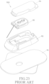
- a conventional sensing device 900 disclosed in U.S. Patent No. 7899511 includes a base 92, an adhesive base 91 that is adapted for adhering the base 92 onto a host's skin (not shown), a biosensor 93 that is mounted in the base 92, and a transducer 94 that is mounted to the base 92 and that is connected to the biosensor 93.
- the biosensor 93 is inserted beneath the host's skin for measuring a physiological signal corresponding to the blood glucose concentration level, and the transducer 94 receives the physiological signal from the biosensor 93 and forwards the physiological signal to an external device (not shown).
- the biosensor 93 includes a fixed seat 931, an elongated sensing member 932 that is fixedly mounted to the fixed seat 931, and two contactor heads 933 that are fixedly mounted to the fixed seat 931 and that are in contact with the sensing member 932.
- contact points (not shown) at a bottom end of the transducer 94 are to be in direct contact with the contactor heads 933 for enabling electric connection between the transducer 94 and the sensing member 932.
- the thickness of each of the contactor heads 933 cannot be smaller than the distance between the transducer 94 and the sensing member 932.
- the contactor heads 933 may not be able to properly enable electric connection between the biosensor 93 and the transducer 94 due to manufacturing errors, such as misalignment of the contactor heads 933, or the contactor heads 933 having the thickness different from the distance between the transducer 94 and the sensing member 932.
- WO 2017/116915 A1 discloses a device for measuring an analyte in a person wherein springs are implemented as providing a low-resistance and mechanically stable electrical connection between a sensor module and an associated electronics unit such as a transmitter. Coupling the electronics unit to the sensor module can compress the springs to create an electrical connection between the sensor module and the electronics unit.
- an object of the disclosure is to provide a physiological signal monitoring device that can alleviate the drawbacks of the prior art.
- the invention is defined by the appended claims.
- the physiological signal monitoring device is for sensing a physiological signal in an analyte of a host, and includes a sensing member and a transmitter.
- the sensing member includes a signal sensing end adapted to be inserted underneath a skin of the host to sense the physiological signal, and a signal output end for outputting the physiological signal.
- the transmitter is connected to the sensing member for receiving, processing and transmitting the physiological signal, and includes a circuit board and a connecting port.
- the circuit board has a plurality of electrical contacts.
- the connecting port is connected to the circuit board and has a socket which is communicated to the circuit board, and a plurality of conducting balls which are received within the connecting port.
- the sensing member is removably inserted into the socket.
- Each of the steel balls has one side electrically connected to a respective one of the electrical contacts of the circuit board and another side electrically connected to the signal output end of the sensing member for electric connection between the respective one of the electrical contacts and the signal output end.
- Each of the steel balls is frictionally rotated by the sensing member during insertion of the sensing member into the socket and removal of the sensing member from the socket.
- the physiological signal monitoring device is for sensing a physiological signal in an analyte of a host, and includes a sensing member and a transmitter.
- the sensing member includes a signal sensing end adapted to be inserted underneath a skin of the host to sense the physiological signal, and a signal output end for outputting the physiological signal.
- the transmitter is connected to the sensing member for receiving, processing and transmitting the physiological signal, and includes a circuit board and a connecting port.
- the circuit board has a plurality of electrical contacts.
- the connecting port is connected to the circuit board and has a socket which is communicated to the circuit board, and a plurality of conducting balls which are received within the connecting port.
- the sensing member is removably inserted into the socket.
- Each of the steel rings has one side electrically connected to a respective one of the electrical contacts of the circuit board and another side electrically connected to the signal output end of the sensing member for electric connection between the respective one of the electrical contacts and the signal output end.
- Each of the steel rings is frictionally rotated by the sensing member during insertion of the sensing member into the socket and removal of the sensing member from the socket.
- a first embodiment of the physiological signal monitoring device is adapted to be mounted to a skin surface of a host (not shown), and is adapted for measuring at least one analyte of the host and for sending a corresponding type of physiological signal.
- the physiological signal monitoring device is for measuring the blood glucose concentration in the interstitial fluid (ISF) of the host, and is meant to be mounted to the skin surface for two weeks, but is not restricted to such.
- ISF interstitial fluid
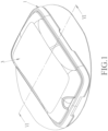
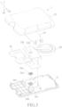
- the physiological signal monitoring device includes a base 1 that is adapted to be mounted to the skin surface of the host, a biosensor 2 that is mounted to the base 1 and that is adapted to be partially inserted underneath the skin surface of the host, and a transmitter 3 that covers and is removably coupled to the base 1 in a direction of a first axis (D1) and that is connected to the biosensor 2.
- the biosensor 2 is adapted for measuring at least one analyte of the host and for sending a corresponding physiological signal to the transmitter 3, while the transmitter 3 receives, processes, and outputs the physiological signal to an external device (not shown) for monitoring purposes.
- the transmitter 3 is permitted to be separated from the biosensor 2 and the base 1 to be reused with a new set of the base 1 and biosensor 2.
- the base 1 includes a base body 11, and an adhesive pad 16 that is mounted to a bottom surface 116 (see FIG. 6 ) of the base body 11 and that is permitted for attaching the base body 11 to the skin surface of the host.
- the biosensor 2 includes a fixed seat 21 that is mounted to the base body 11, and a sensing member 22 that is mounted to the fixed seat 21 and that extends through the base body 11. The fixed seat 21 is mounted between the transmitter 3 and the base 1 when the transmitter 3 is coupled to the base 1.
- the fixed seat 21 has a bottom surface 211 and a top surface 212.
- the sensing member 22 has a signal sensing end 222 that is adapted to be inserted underneath the skin surface of the host for measuring the physiological signal of the host, and a signal output end 221 that is adapted to output the physiological signal received from the signal sensing end 222.
- the signal sensing end 222 protrudes from the bottom surface 211 of the fixed seat 21, and the signal output end 221 protrudes from the top surface 212 of the fixed seat 21.
- the sensing member 22 includes a base board 225, a plurality of electrodes 226 mounted to a surface of the base board 225, and an analyte sensing layer (not shown) that covers the electrodes 226 and the surface of the base board 225.
- the analyte sensing layer is provided for reacting with the at least one analyte of the host, and the electrodes 226 includes signal receiving electrodes that detect outcome of the reaction, and signal sending electrodes that generate an electric signal indicating the outcome of the reaction.
- the electric signal is the physiological signal that indicates glucose levels in the interstitial fluid. Specific roles of the electrodes 226 will be elaborated later.
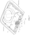
- the transmitter 3 includes a bottom casing 31 that is proximate to the base body 11, a top casing 32 that is mounted to the bottom casing 31 to define an inner space 30, a circuit board 33 that is disposed in the inner space 30, a processing unit 34 (see FIGS. 10 and 11 ) that is mounted to the circuit board 33, a battery 35 that is disposed in the inner space 30, and a connecting port 36 that is connected to a bottom surface of the circuit board 33 and that extends outwardly from the inner space 30 toward the base body 11.
- the circuit board 33 is permitted to be printed circuit board (PCB) or flexible print circuit (FPC), and is fixedly positioned to the bottom casing 31 via a supporting member 37, which may be made of a metal plate.
- the circuit board 33 has a plurality of electrical contacts 331 that correspond in position to the connecting port 36. In this embodiment, the number of the electrical contacts 331 is eight.
- the processing unit 34 is provided for receiving, processing, and sending the physiological signal, and is connected to the electrical contacts 331.
- the battery 35 is connected to the electrical contacts 331 of the circuit board 33.
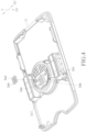
- the connecting port 36 includes a port casing 361 that is mounted to a bottom surface of the circuit board 33 and that extends downwardly toward a bottom surface 311 of the bottom casing 31 in the direction of the first axis (D1), and a plurality of spaced-apart conducting members 364 that are received within the port casing 361.
- the number of the conducting members 364 is eight.
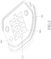
- the port casing 361 is formed with a plurality of grooves 366 open toward the circuit board 33 and respectively receiving the conducting members 364 therein, and a socket 367 that extends toward the base body 11 in the direction of the first axis (D1) and that is communicated to the grooves 366.
- the conducting members 364 are respectively and rotatably received within the grooves 366.
- the socket 367 is provided to hold the signal output end 221 of the sensing member 22.
- a cross section of an outer periphery of the grooves 336 perpendicular to the first axis (D1) is substantially dovetail-shaped, and each of the grooves 336 tapers toward the socket 367 for preventing each of the conducting members 364 from escaping the respective one of the grooves 336.
- the conducting members 364 are elastic, and are disposed at two opposite sides of the socket 367.
- the conducting members 364 are conducting coil springs.
- Each of the conducting members 364 contacts with the circuit board 33 at one side along with a first direction, and contacts with the sensing member 22 at another side along a second direction wherein the first direction is nonparallel to the second direction. Therefore, the electric connection between the electrical contacts 331 of the circuit board 33 and the signal output end 221 of the sensing member 22 is provide when the sensing member 22 is inserted into the socket 367.
- each of the conducting members 364 has one side that is in contact with (and electrically connected to) a respective one of the electrical contacts 331 of the circuit board 33 in the direction of the first axis (D1) (i.e., the first direction) and another side that is in contact with (and electrically connected to) the electrodes 226 on the signal output end 221 of the sensing member 22 in a direction of a second axis (D2) (i.e., the second direction) for positioning the sensing member 22 when it is inserted into the socket 367 and for enabling electric connection between the electrical contacts 331 of the circuit board 33 and the signal output end 221 of the sensing member 22.
- D1 first axis
- D2 second axis
- the first and second axes (D1, D2) are substantially perpendicular to each other, but may not be restricted as such in other embodiments.
- the conducting coil springs have high degrees of freedom such that each of the conducting members 364 is rotated relative to the grooves 366 during insertion of the sensing member 22 into the socket 367 and removal of the sensing member 22 from the socket 367 along the first axis (D1), thereby reducing friction between the socket 367 and the sensing member 22 and facilitating the reuse of the transmitter 3.
- each of the conducting members 364 has one end welded to the port casing 361 so that one end of each of the conducting members 364 is fixed on the respective one of the grooves 366.
- the conducting members 364 are conducting coil springs
- each of the conducting members 364 has the following properties: the wire diameter thereof is smaller than 1 millimeter (mm), preferably 0.1 mm; the outer diameter thereof ranges from 0.5 mm to 1.8 mm, preferably 1.1 mm; the free length thereof ranges from 0.2 mm to 0.8 mm, preferably 0.44 mm to 0.56 mm.
- Each of the conducting members 364 has a helical portion 365a with two to six turns (three turns in this embodiment), thereby providing multi-point contacts with the respective one of the electrical contacts 331 of the circuit board 33 and the signal output end 221 of the sensing member 22.
- parameters such as the wire diameter and the number of turns of each of the conducting members 364 are designed in consideration to the elasticity of the conducting members 364, and the outer diameter and the free length of each of the conducting members 364 are designed in such a way that each of the conducting members 364 is slightly larger than a space of the respective one of the grooves 366, so that the conducting members 364 are in stable contact with the electrical contacts 331 of the circuit board 33 and the electrodes 226 on the signal output end 221 of the sensing member 22(see FIGS. 2 and 11 ).
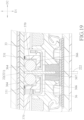
- the conducting members 364 of the connecting port 36 which were originally conductive coil springs in the first embodiment, are steel balls or steel rings (i.e., rigid components) instead.
- the connecting port 36 further includes a plurality of elastic members 369, each of which is mounted in the respective one of the grooves 366 and is mounted between the port casing 361 and a respective one of the conducting members 364.
- the elastic members 369 are made of elastic materials such as rubber, and each of the conducting members 364 has one side contacted with the respective elastic member 369 and another side contacted with the electrodes 226 of the the signal output end 221 along an axis parallel to the second axis (D2).
- the conducting members 364 in this modification functions similarly to that of the first embodiment: enabling electric connection between the electrical contacts 331 and the signal output end 221, and being frictionally moved by the sensing member 22 to rotate in the grooves 366.
- the elastic members 369 ensure that the conducting members 364 are in stable contact with the sensing member 22 and the circuit board 33 along the directions parallel to the first axis (D1) and the second axis (D2) respectively.
- the conducting members 364 are conducting coil strings, each of which has an extended section 365b that extends along an inner surface of the port casing 361 toward the circuit board 33, and that is connected to the respective one of the electrical contacts 331 in the direction of the first axis (D1).
- the processing unit 34 receives the electric signal from the sensing member 22 and sends a corresponding physiological signal.
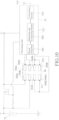
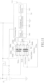
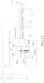
- the processing unit 34 includes a signal amplifier 341 receiving and amplifying the electric signal, a measuring and computing module 342 that converts the amplified electric signal sequentially into a physiological signal corresponding to the glucose level, and a transmitting module 343 that sends the physiological digital signal to an external device (not shown) via an antenna 344.
- the abovementioned physiological signal corresponding to the glucose level is electric current.
- the conducting members 364 are conducting coil springs and include two power-supplying conducting members 364a, four sensing conducting members 364b, and two transmitting conducting members 364c.
- the electrodes 226 of the sensing member 22 are in contact with the conducting members 364 to be respectively and electrically connected to the electrical contacts 331 of the circuit board 33 for the purposes of supplying power, sensing and transmitting data.
- the power-supplying conducting members 364a and the electrodes 226 cooperatively form a switch.
- the sensing conducting members 364b are connected to the processing unit 34.
- the transmitting conducting members 364c are connected to the processing unit 34 as well, and transmit data to the external device via the transmitting module 343 and the antenna 344.
- type of data transmission may be wireless transmission (Bluetooth, Wifi, NFC), but may be wired transmission (USB cable) in other embodiments.
- the number of the electrodes 226 of the sensing member 22 is five.
- the electrodes 226 include a working electrode 226a, a reference electrode 226b, a power-supplying electrode 226e, and two electrical contact sections 226d.
- the switch formed by the conducting members 364a is in an open circuit state, so that the battery 35 is in a non-power supplying state.
- the power-supplying electrode 226e of the sensing member 22 is in contact with the power-supplying conducting members 364a to be electrically connected with the electrical contacts 331 of the circuit board 33, such that the switch is in a closed circuit state and the battery 35 is switched to a power supplying state for supplying power to the sensing member 22 and the processing unit 34 for performing measurement of the analyte.
- each of the working and reference electrode 226a, 226b is in contact with corresponding two of the sensing conducting members 364b to be electrically connected to the electrical contacts 331 of the circuit board 33, such that the processing unit 34 receives, processes, and sends the physiological signal to the external device.
- the electrical contact sections 226d are permitted to be respectively and electrically connected to the transmitting conducting members 364c. In this embodiment, the electrical contact sections 226d has signal receiving and signal sending electrodes.
- a circuit layout of the transmitter 3 can be modified according to the various requirement of the product.
- the sensing member 22 begins measurement of the physiological signal of the host without power control by the processing unit 34 when the sensing member 22 is inserted into the socket 367.
- the circuit concerning to the power supply can be rearranged in other embodiments, so there is no more detailed description herein.
- the socket 367 of the connecting port 36 is further adapted for additional transmission device (not shown) or charging device (not shown) to be inserted thereinto.
- additional transmission device not shown
- charging device not shown
- the socket 367 of the connecting port 36 is further adapted for additional transmission device (not shown) or charging device (not shown) to be inserted thereinto.
- a connector (or an electrode) of the additional transmission device may be inserted into the socket 367 to provide electric connection and data transmission between the processing unit 34 and the additional transmission device through the transmitting conducting members 364c.
- the transmitting conducting members 364c are permitted to be electrically connected to the additional transmission device for exchanging data (default data or calibration data) before the transmitter 3 is connected to the biosensor 2 and the base 1.
- the charging device may be inserted into the socket 367 to recharge the transmitter 3 through the power-supplying conducting members 364a, which electrically interconnect the electrical contacts 331 of the circuit board 33 and the charging device.
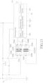
- the electrodes 226 of the sensing member 22 include a working electrode 226a, a counter electrode 226f, a power-supplying electrode 226e, and two electrical contact sections 226d, and the number of the conducting members 364 of the transmitter 3 is six.
- the conducting members 364 are conducting coil springs and include two power-supplying conducting members 364a, two sensing conducting members 364b, and two transmitting conducting members 364c.
- the power-supplying electrode 226e of the sensing member 22 is in contact with the power-supplying conducting members 364a to be electrically connected with the electrical contacts 331 of the circuit board 33.
- each of the working and counter electrode 226a, 226f is in contact with a respective one of the sensing conducting members 364b to be electrically connected to the electrical contacts 331 of the circuit board 33, such that the processing unit 34 receives, processes, and sends the physiological signal to the external device.
- the electrical contact sections 226d are permitted to be respectively and electrically connected to the transmitting conducting members 364c.
- the electrodes 226 of the sensing member 22 include a working electrode 226a, a counter electrode 226f, and two power-supplying electrodes 226e, and the number of the conducting members 364 of the transmitter 3 is four.
- the conducting members 364 are conducting coil springs and include two power-supplying conducting members 364a and two sensing conducting members 364b.
- each of the working and counter electrode 226a, 226f is in contact with a respective one of the sensing conducting members 364b to be electrically connected to the electrical contacts 331 of the circuit board 33, such that the processing unit 34 receives, processes, and sends the physiological signal to the external device.
- the electrical contacts 331 of the circuit board 33 and the electrodes 226 of the sensing member 22 are able to be electrically connected to activate the processing unit 34.
- the conducting coil springs in the abovementioned modifications may be conducting components of other forms.
- the transmitter 3 is coupled to the biosensor 2 assembled on the base 1 wherein the base 1 is attached on the host skin. Accordingly, the sensing member 22 of the biosensor 2 is inserted into the socket 367 of the transmitter 3 for the measurement of the analyte.
- the first embodiment of the physiological signal monitoring device provides the following benefits:
- FIGS. 15 and 16 illustrate a second embodiment of the physiological signal monitoring device wherein the difference between the first embodiment and the second embodiment is described as follows.
- the port casing 361 of the connecting port 36 has a plurality of slanted surfaces 368 respectively disposed in the grooves 366 and facing the circuit board 33 and the sensing member 22. Therefore, the conducting members 364 are forced against the circuit board 33 and the sensing member 22 with force vector provided by the slanted surfaces 368 to ensure the contact therebetween and enhance the mobility of the conducting members 364. Moreover, the conducting members 364 could return to the predetermined position after the removal of the sensing member 22 from the socket 367 because of the slanted surfaces 368 such that the contact problem resulting in electric disconnection between the conducting member 364 and the sensing member 22 could be solved. In other embodiments, the conducting members 364 could be modified as hard components(ex. steel ball or steel ring) with the elastic members 369 configured between the conducting members 364 and the slanted surfaces 368.
- FIG. 17 illustrates a third embodiment of the physiological signal monitoring device wherein the difference between the first embodiment and the third embodiment is described as follows.
- each of the conducting members 364 of the connecting port 36 is a leaf spring with one end contacted with the corresponding electrical contact 331 of the circuit board 33 along the first axis (D1) and another end contacted with the electrodes 226 of the sensing member 22 along the second axis (D2). Accordingly, the sensing member 22 is stably held within the socket 367 by the leaf springs 364 to provide reliable electric connection and signal transmission between the circuit board 33 and the sensing member 22.
- FIG. 18 illustrates a fourth embodiment of the physiological signal monitoring device wherein the difference between the first embodiment and the fourth embodiment is described as follows.
- the conducting members 364 are conducting coil springs.
- the connecting port 36 further includes a plurality of metal plates 370 respectively connected to the electrical contacts 331.
- the metal plates 370 are welded to the electrical contacts 331 via surface mount technology (SMT), and extended toward the grooves 366 to be disposed between the port casing 361 and the conducting members 364. Therefore, each of the conducting members 364 coaxially contacted with a respective one of the metal plates 370 and the electrodes 226 of the sensing member 22 along an axis parallel to the second axis (D2) to provide reliable electric connection between the circuit board 33 and the sensing member 22.
- SMT surface mount technology
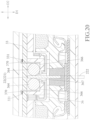
- FIGS. 19 and 20 illustrate other modifications of the fourth embodiment, in which the conducting members 364 are steel balls or steel rings instead wherein the metal plates 370 are welded to the electrical contacts 331 via surface mount technology (SMT) shown as FIG. 19 or dual in-line package (DIP) shown as FIG. 20 .
- SMT surface mount technology
- DIP dual in-line package
- the conducting members 364 of the connecting port 36 are disposed at two opposite sides of the socket 367.
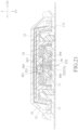
- the conducting members 364 of the connecting port 36 can be disposed at single side of the socket 367 instead, such that only single side of the sensing member 22 is abutted against the conducting members 364. Referring to FIGS. 21 and 22 , the sensing member 22 is stably held within the socket 367 by the elastic conducting members 364 and the port casing 361 to provide reliable electric connection between the circuit board 33 and the sensing member 22.
- the conducting members 364 are lateraly configured at the socket 367 to contact with the electrodes 226 of the sensing member 22 and the electrical contacts 33 1 of the circuit board 33 after the transmitter 3 is coupled to the biosensor 2, thereby providing the reliable electric connection therebetween and holding of the sensing member 22. Moreover, the conducting members 364 are rotated relative to the grooves 366 during insertion or removal of the sensing member 22 from the socket 367 to reduce friction resistance between conducting members 364 and the sensing member 22 and facilitate the reuse of the transmitter 3.
- the conducting members 364 can be conducting coil springs, steel balls/rings with the elastic members 369 or metal plates 370 to provide bidirectional or coaxial connection between the sensing member 22 and the circuit- board 33. Therefore, the electrodes 226 of various functions are electrically connected with the electrical contacts 331 of single connecting port 36 to activate the power supply, signal sensing and date transmission.
- this disclosure further discloses a plurality of embodiments as defined by the claims, with each embodiment comprising the claim element(s) of the respective claim and the claim element(s) of any claim upon which the respective claim depends.
Landscapes
- Health & Medical Sciences (AREA)
- Life Sciences & Earth Sciences (AREA)
- Physics & Mathematics (AREA)
- Engineering & Computer Science (AREA)
- Surgery (AREA)
- Animal Behavior & Ethology (AREA)
- Biomedical Technology (AREA)
- Heart & Thoracic Surgery (AREA)
- Medical Informatics (AREA)
- Molecular Biology (AREA)
- Biophysics (AREA)
- Pathology (AREA)
- General Health & Medical Sciences (AREA)
- Public Health (AREA)
- Veterinary Medicine (AREA)
- Optics & Photonics (AREA)
- Emergency Medicine (AREA)
- Physiology (AREA)
- Computer Networks & Wireless Communication (AREA)
- Measuring And Recording Apparatus For Diagnosis (AREA)
Claims (16)
- Dispositif de surveillance de signal physiologique pour détecter un signal physiologique dans un analyte d'un hôte, comprenant:un élément de détection (22), comportantune extrémité de détection de signal (222) adaptée pour être insérée sous la peau de l'hôte pour détecter le signal physiologique, etune extrémité de sortie de signal (221) destinée à sortir le signal physiologique; etun moyen de transmission (3) connecté audit élément de détection (22) pour recevoir, traiter et transmettre le signal physiologique,dans lequel ledit moyen de transmission (3) comporte par ailleursune carte de circuit imprimé (33) présentant une pluralité de contacts électriques (331), etun orifice de connexion (36) connecté à ladite carte de circuit imprimé (33) et présentant une douille (367) qui est en communication avec ladite carte de circuit imprimé (33), et une pluralité d'éléments conducteurs (364) qui sont reçus dans ledit orifice de connexion (36);dans lequel ledit élément de détection (22) est inséré dans ladite douille (367);dans lequel chacun desdits éléments conducteurs (364) présente un côté connecté électriquement à l'un respectif desdits contacts électriques (331) de ladite carte de circuit imprimé (33) et un autre côté connecté électriquement à ladite extrémité de sortie de signal (221) dudit élément de détection (22) pour une connexion électrique entre l'un respectif parmi lesdits contacts électriques (331) et ladite extrémité de sortie de signal (221); etcaractérisé par le fait quel'élément de détection (22) est inséré de manière amovible dans la douille (367), etles éléments conducteurs sont des billes en acier (364),dans lequel chacune desdites billes en acier (364) est entraînée en rotation par friction par ledit élément de détection (22) pendant l'insertion dudit élément de détection (22) dans ladite douille (367) et le retrait dudit élément de détection (22) de ladite douille (367).
- Dispositif de surveillance de signal physiologique selon la revendication 1, caractérisé par le fait que ledit orifice de connexion (36) comporte par ailleurs un boîtier d'orifice (361) monté sur ladite carte de circuit imprimé (33) et formé par ladite douille (367), et une pluralité de rainures (366) en communication avec ladite douille pour recevoir lesdites billes en acier (364) à l'intérieur de cette dernière.
- Dispositif de surveillance de signal physiologique selon la revendication 2, caractérisé par le fait que ledit orifice de connexion (36) comporte par ailleurs une pluralité d'éléments élastiques (369), chacun desdits éléments élastiques (369) étant monté entre ledit boîtier d'orifice (361) et l'une respective desdites billes en acier (364).
- Dispositif de surveillance de signal physiologique selon la revendication 2, caractérisé par le fait que lesdites billes en acier (364) dudit orifice de connexion (36) sont disposées d'un côté de ladite douille (367).
- Dispositif de surveillance de signal physiologique selon la revendication 2, caractérisé par le fait que lesdites billes en acier (364) dudit orifice de connexion (36) sont disposées de deux côtés opposés de ladite douille (367).
- Dispositif de surveillance de signal physiologique selon la revendication 1, caractérisé par le fait que chacune desdites billes en acier (364) présente ledit un côté en contact avec un desdits contacts électriques (331) le long d'une direction d'un premier axe (D1) et ledit autre côté en contact avec ladite extrémité de sortie de signal (221) le long d'une direction d'un deuxième axe (D2).
- Dispositif de surveillance de signal physiologique selon la revendication 1, caractérisé par le fait que ledit orifice de connexion (36) comporte par ailleurs une pluralité de plaques métalliques (370) connectées respectivement auxdits contacts électriques (331) pour forcer lesdites billes en acier (364) contre ledit élément de détection (22), chacune desdites billes en acier (364) étant de manière coaxiale en contact avec une respective desdites plaques métalliques (370) et ladite extrémité de sortie de signal (221) dudit élément de détection (22).
- Dispositif de surveillance de signal physiologique selon la revendication 1, caractérisé par le fait que ledit élément de détection (22) est inséré dans ladite douille (367) le long d'une direction d'un premier axe (D1), et ladite extrémité de sortie de signal (221) dudit élément de détection (22) est connectée électriquement à chacune desdites billes en acier (364) le long d'une direction d'un deuxième axe (D2).
- Dispositif de surveillance de signal physiologique pour détecter un signal physiologique dans un analyte d'un hôte, comprenant:un élément de détection (22), comportantune extrémité de détection de signal (222) adaptée pour être insérée sous la peau de l'hôte pour détecter le signal physiologique, etune extrémité de sortie de signal (221) destinée à sortir le signal physiologique; etun moyen de transmission (3) connecté audit élément de détection (22) pour recevoir, traiter et transmettre le signal physiologique,dans lequel ledit moyen de transmission (3) comporteune carte de circuit imprimé (33) présentant une pluralité de contacts électriques (331), etun orifice de connexion (36) connecté à ladite carte de circuit imprimé (33) et présentant une douille (367) qui est en communication avec ladite carte de circuit imprimé (33), et une pluralité d'éléments conducteurs (364) qui sont reçus dans l'orifice de connexion (36):dans lequel ledit élément de détection (22) est inséré dans ladite douille (367);dans lequel chacun desdits éléments conducteurs (364) présente un côté connecté électriquement à l'un respectif desdits contacts électriques (331) de ladite carte de circuit imprimé (33) et un autre côté connecté électriquement à ladite extrémité de sortie de signal (221) dudit élément de détection (22) pour une connexion électrique entre l'un respectif desdits contacts électriques (331) et ladite extrémité de sortie de signal (221); etcaractérisé par le fait quel'élément de détection (22) est inséré de manière amovible dans la douille (367), etles éléments conducteurs sont des anneaux en acier (364),dans lequel chacun desdits anneaux en acier (364) est entraîné en rotation par friction par ledit élément de détection (22) pendant l'insertion dudit élément de détection (22) dans ladite douille (367) et le retrait dudit élément de détection (22) de ladite douille (367).
- Dispositif de surveillance de signal physiologique selon la revendication 9, caractérisé par le fait que ledit orifice de connexion (36) comporte par ailleurs un boîtier d'orifice (361) monté sur ladite carte de circuit imprimé (33) et formé par ladite douille (367), et une pluralité de rainures (366) en communication avec ladite douille (367) pour recevoir lesdits anneaux en acier (364) à l'intérieur de cette dernière.
- Dispositif de surveillance de signal physiologique selon la revendication 10, caractérisé par le fait que ledit orifice de connexion (36) comporte par ailleurs une pluralité d'éléments élastiques (369), chacun desdits éléments élastiques (369) étant monté entre ledit boîtier d'orifice (361) et l'un respectif desdits anneaux en acier (364).
- Dispositif de surveillance de signal physiologique selon la revendication 10, caractérisé par le fait que lesdits anneaux en acier (364) dudit orifice de connexion (36) sont disposés d'un côté de ladite douille (367).
- Dispositif de surveillance de signal physiologique selon la revendication 10, caractérisé par le fait que lesdits anneaux en acier (364) dudit orifice de connexion (36) sont disposés sur deux côtés opposés de ladite douille (367).
- Dispositif de surveillance de signal physiologique selon la revendication 9, caractérisé par le fait que chacun desdits anneaux en acier (364) présente ledit un côté en contact avec l'un respectif desdits contacts électriques (331) le long d'une direction d'un premier axe (D1) et ledit autre côté en contact avec ladite extrémité de sortie de signal (221) le long d'une direction d'un deuxième axe (D2).
- Dispositif de surveillance de signal physiologique selon la revendication 9, caractérisé par le fait que ledit orifice de connexion (36) comporte par ailleurs une pluralité de plaques métalliques (370) connectées respectivement auxdits contacts électriques (331) pour forcer lesdits anneaux en acier (364) contre ledit élément de détection (22), chacun desdits anneaux en acier (364) étant de manière coaxiale en contact avec l'une respective desdites plaques métalliques (370) et ladite extrémité de sortie de signal (221) dudit élément de détection (22).
- Dispositif de surveillance de signal physiologique selon la revendication 9, caractérisé par le fait que ledit élément de détection (22) est inséré dans ladite douille (367) le long d'une direction d'un premier axe (D1), et ladite extrémité de sortie de signal (221) dudit élément de détection (22) est connectée électriquement à chacun desdits anneaux en acier (364) le long d'une direction d'un deuxième axe (D2).
Applications Claiming Priority (4)
| Application Number | Priority Date | Filing Date | Title |
|---|---|---|---|
| US201962882140P | 2019-08-02 | 2019-08-02 | |
| TW109100852A TWI731545B (zh) | 2019-08-02 | 2020-01-10 | 生理訊號傳感裝置 |
| TW109100968A TWI735138B (zh) | 2019-08-02 | 2020-01-10 | 生理訊號傳感裝置 |
| TW109109241A TWI737223B (zh) | 2019-08-02 | 2020-03-19 | 生理訊號傳感裝置 |
Publications (3)
| Publication Number | Publication Date |
|---|---|
| EP3771428A1 EP3771428A1 (fr) | 2021-02-03 |
| EP3771428C0 EP3771428C0 (fr) | 2024-11-13 |
| EP3771428B1 true EP3771428B1 (fr) | 2024-11-13 |
Family
ID=71899685
Family Applications (1)
| Application Number | Title | Priority Date | Filing Date |
|---|---|---|---|
| EP20189221.3A Active EP3771428B1 (fr) | 2019-08-02 | 2020-08-03 | Dispositif de surveillance de signal physiologique |
Country Status (2)
| Country | Link |
|---|---|
| US (2) | US11737689B2 (fr) |
| EP (1) | EP3771428B1 (fr) |
Families Citing this family (5)
| Publication number | Priority date | Publication date | Assignee | Title |
|---|---|---|---|---|
| CN113827231B (zh) * | 2021-11-26 | 2022-03-18 | 上海微创生命科技有限公司 | 用于经皮植入传感器的助针器及医疗装置 |
| TWD226583S (zh) * | 2022-08-31 | 2023-07-21 | 華廣生技股份有限公司 | 生理訊號監測貼片 |
| TWD226582S (zh) * | 2022-08-31 | 2023-07-21 | 華廣生技股份有限公司 | 生理訊號監測貼片 |
| TWD226584S (zh) * | 2022-08-31 | 2023-07-21 | 華廣生技股份有限公司 | 生理訊號監測貼片 |
| WO2024249941A1 (fr) * | 2023-06-02 | 2024-12-05 | Laxmi Therapeutic Devices, Inc. | Applicateurs pour dispositifs de surveillance de glucose et procédés d'application de dispositifs de surveillance de glucose |
Citations (1)
| Publication number | Priority date | Publication date | Assignee | Title |
|---|---|---|---|---|
| US20190074644A1 (en) * | 2017-06-30 | 2019-03-07 | Benchmark Electronics, Inc. | Medical Lead Connectors with Contact Electrodes |
Family Cites Families (72)
| Publication number | Priority date | Publication date | Assignee | Title |
|---|---|---|---|---|
| US7899511B2 (en) | 2004-07-13 | 2011-03-01 | Dexcom, Inc. | Low oxygen in vivo analyte sensor |
| US8465425B2 (en) | 1998-04-30 | 2013-06-18 | Abbott Diabetes Care Inc. | Analyte monitoring device and methods of use |
| US6338790B1 (en) | 1998-10-08 | 2002-01-15 | Therasense, Inc. | Small volume in vitro analyte sensor with diffusible or non-leachable redox mediator |
| US9795334B2 (en) | 2002-04-19 | 2017-10-24 | Sanofi-Aventis Deutschland Gmbh | Method and apparatus for penetrating tissue |
| US6964871B2 (en) | 2002-04-25 | 2005-11-15 | Home Diagnostics, Inc. | Systems and methods for blood glucose sensing |
| US9763609B2 (en) | 2003-07-25 | 2017-09-19 | Dexcom, Inc. | Analyte sensors having a signal-to-noise ratio substantially unaffected by non-constant noise |
| US7920906B2 (en) | 2005-03-10 | 2011-04-05 | Dexcom, Inc. | System and methods for processing analyte sensor data for sensor calibration |
| US6878013B1 (en) * | 2003-12-02 | 2005-04-12 | Edgar G. Behan | Connector apparatus for a medical device |
| US8792955B2 (en) | 2004-05-03 | 2014-07-29 | Dexcom, Inc. | Transcutaneous analyte sensor |
| US8989833B2 (en) | 2004-07-13 | 2015-03-24 | Dexcom, Inc. | Transcutaneous analyte sensor |
| US7783333B2 (en) | 2004-07-13 | 2010-08-24 | Dexcom, Inc. | Transcutaneous medical device with variable stiffness |
| US8886272B2 (en) | 2004-07-13 | 2014-11-11 | Dexcom, Inc. | Analyte sensor |
| US7285846B1 (en) | 2005-02-22 | 2007-10-23 | Littelfuse, Inc. | Integrated circuit package with ESD protection |
| US20090076360A1 (en) | 2007-09-13 | 2009-03-19 | Dexcom, Inc. | Transcutaneous analyte sensor |
| US9615851B2 (en) * | 2005-11-11 | 2017-04-11 | Waveform Technologies, Inc. | Method and apparatus for insertion of a sensor |
| US7887682B2 (en) | 2006-03-29 | 2011-02-15 | Abbott Diabetes Care Inc. | Analyte sensors and methods of use |
| WO2008105768A1 (fr) | 2007-03-01 | 2008-09-04 | Dexcom, Inc. | Détecteur d'analyte |
| US20200037875A1 (en) | 2007-05-18 | 2020-02-06 | Dexcom, Inc. | Analyte sensors having a signal-to-noise ratio substantially unaffected by non-constant noise |
| US8583204B2 (en) | 2008-03-28 | 2013-11-12 | Dexcom, Inc. | Polymer membranes for continuous analyte sensors |
| US8280474B2 (en) | 2008-06-02 | 2012-10-02 | Abbott Diabetes Care Inc. | Reference electrodes having an extended lifetime for use in long term amperometric sensors |
| US8155722B2 (en) | 2008-06-02 | 2012-04-10 | Abbott Diabetes Care Inc. | Reference electrodes having an extended lifetime for use in long term amperometric sensors |
| US8700114B2 (en) | 2008-07-31 | 2014-04-15 | Medtronic Minmed, Inc. | Analyte sensor apparatuses comprising multiple implantable sensor elements and methods for making and using them |
| TWI424832B (zh) | 2008-12-15 | 2014-02-01 | 波提亞斯數位康健公司 | 與身體有關的接收器及其方法 |
| US9402544B2 (en) | 2009-02-03 | 2016-08-02 | Abbott Diabetes Care Inc. | Analyte sensor and apparatus for insertion of the sensor |
| US8096838B2 (en) * | 2009-03-11 | 2012-01-17 | Bal Seal Engineering, Inc. | Header assembly for implantable medical devices |
| US20100279558A1 (en) * | 2009-04-29 | 2010-11-04 | Gordon Leon | Electrical contact assemblies with canted coil springs |
| EP2266458A1 (fr) | 2009-06-23 | 2010-12-29 | Roche Diagnostics GmbH | Capteur pour mesures in-vivo |
| US9351677B2 (en) | 2009-07-02 | 2016-05-31 | Dexcom, Inc. | Analyte sensor with increased reference capacity |
| EP3689237B1 (fr) | 2009-07-23 | 2021-05-19 | Abbott Diabetes Care, Inc. | Procédé de fabrication et système de mesure d'analytes continue |
| US9125603B2 (en) | 2009-08-11 | 2015-09-08 | Abbott Diabetes Care Inc. | Analyte sensor ports |
| JP5795584B2 (ja) | 2009-08-31 | 2015-10-14 | アボット ダイアベティス ケア インコーポレイテッドAbbott Diabetes Care Inc. | 医療用装置 |
| EP2482724A2 (fr) | 2009-09-30 | 2012-08-08 | Dexcom, Inc. | Capteur d'analyte transcutané |
| US8500979B2 (en) | 2009-12-31 | 2013-08-06 | Intel Corporation | Nanogap chemical and biochemical sensors |
| ES2881798T3 (es) | 2010-03-24 | 2021-11-30 | Abbott Diabetes Care Inc | Insertadores de dispositivos médicos y procedimientos de inserción y uso de dispositivos médicos |
| TWI439689B (zh) | 2010-09-23 | 2014-06-01 | 華廣生技股份有限公司 | Electrochemical test specimen |
| WO2012097879A1 (fr) | 2011-01-21 | 2012-07-26 | St. Jude Medical Ab | Dispositif implantable avec caractéristiques de surface améliorées |
| TWI569773B (zh) | 2011-05-26 | 2017-02-11 | 華廣生技股份有限公司 | 量測一生理參數的系統及方法 |
| TWI452997B (zh) | 2011-10-05 | 2014-09-21 | Univ Kun Shan | 具有奈米結構之射頻生醫感測晶片 |
| AU2012352560B2 (en) | 2011-12-11 | 2017-01-19 | Abbott Diabetes Care Inc. | Analyte sensor devices, connections, and methods |
| US20130267812A1 (en) | 2012-04-04 | 2013-10-10 | Dexcom, Inc. | Transcutaneous analyte sensors, applicators therefor, and associated methods |
| US10598627B2 (en) | 2012-06-29 | 2020-03-24 | Dexcom, Inc. | Devices, systems, and methods to compensate for effects of temperature on implantable sensors |
| DE102012107835A1 (de) | 2012-08-24 | 2014-02-27 | Albert-Ludwigs-Universität Freiburg | Medizinisches Implantat sowie Verfahren zu dessen Herstellung |
| EP4736749A2 (fr) | 2013-04-30 | 2026-05-06 | Abbott Diabetes Care Inc. | Systèmes, dispositifs et procédés d'activation de dispositif électrique éco-énergétique |
| EP3862041B1 (fr) * | 2013-06-25 | 2023-10-25 | ResMed Pty Ltd | Ensemble de connexion de sortie |
| US10667711B1 (en) | 2013-09-25 | 2020-06-02 | Bardy Diagnostics, Inc. | Contact-activated extended wear electrocardiography and physiological sensor monitor recorder |
| CN104887242B (zh) | 2014-03-07 | 2018-08-28 | 上海移宇科技股份有限公司 | 分析物传感系统 |
| EP2954929A1 (fr) * | 2014-06-10 | 2015-12-16 | BIOTRONIK SE & Co. KG | Ensemble connecteur de conducteur, dispositif médical et son procédé de fabrication |
| EP3171768B1 (fr) | 2014-08-01 | 2020-09-16 | LifeLens Technologies, LLC | Systèmes de surveillance physiologique modulaire |
| US9770598B2 (en) * | 2014-08-29 | 2017-09-26 | Boston Scientific Neuromodulation Corporation | Systems and methods for making and using improved connector contacts for electrical stimulation systems |
| US10456064B2 (en) | 2014-09-03 | 2019-10-29 | Nova Biomedical Corporation | Subcutaneous sensor inserter and method |
| US10722160B2 (en) | 2014-12-03 | 2020-07-28 | The Regents Of The University Of California | Non-invasive and wearable chemical sensors and biosensors |
| GB201510765D0 (en) | 2015-06-18 | 2015-08-05 | Inside Biometrics Ltd | Method, apparatus and electrochemical test device |
| WO2017004531A1 (fr) | 2015-07-02 | 2017-01-05 | The Board Of Trustees Of The University Of Illinois | Dispositifs médicaux souples entièrement implantables pour une interface avec un tissu biologique |
| EP3328270B1 (fr) * | 2015-07-31 | 2022-04-27 | Koninklijke Philips N.V. | Connecteurs à chargement latéral avec câblage en ligne pour utilisation avec des dispositifs intravasculaires et systèmes et procédés associés |
| WO2017062178A1 (fr) | 2015-10-05 | 2017-04-13 | Autonomix Medical, Inc. | Générateur de couple intelligent et ses procédés d'utilisation |
| CN108024716B (zh) | 2015-10-21 | 2022-04-29 | 德克斯康公司 | 经皮分析物传感器、其施加器以及相关联方法 |
| DE202016009211U1 (de) | 2015-12-30 | 2024-04-08 | Dexcom, Inc. | Systeme für transkutane Analytsensoren |
| ES2961001T3 (es) | 2016-01-19 | 2024-03-07 | Hoffmann La Roche | Conjunto de sensor y procedimiento para detectar al menos un analito en un líquido corporal |
| SMT202400475T1 (it) | 2016-02-05 | 2025-01-14 | Hoffmann La Roche | Dispositivo medico per rilevare almeno un analita in un fluido corporeo |
| SG11201807715UA (en) | 2016-03-09 | 2018-10-30 | Peerbridge Health Inc | System and method for monitoring conditions of a subject based on wireless sensor data |
| US10765369B2 (en) | 2016-04-08 | 2020-09-08 | Medtronic Minimed, Inc. | Analyte sensor |
| US10765348B2 (en) | 2016-04-08 | 2020-09-08 | Medtronic Minimed, Inc. | Sensor and transmitter product |
| US10420508B2 (en) | 2016-04-08 | 2019-09-24 | Medtronic Minimed, Inc. | Sensor connections |
| US11298059B2 (en) | 2016-05-13 | 2022-04-12 | PercuSense, Inc. | Analyte sensor |
| US11071478B2 (en) | 2017-01-23 | 2021-07-27 | Abbott Diabetes Care Inc. | Systems, devices and methods for analyte sensor insertion |
| WO2018222012A1 (fr) | 2017-06-02 | 2018-12-06 | 주식회사 아이센스 | Ensemble applicateur de capteur pour système de surveillance du glucose en continu |
| JP6866508B2 (ja) | 2017-06-02 | 2021-04-28 | アイセンス,インコーポレーテッド | 連続血糖測定器用センサーアプリケーター組立体 |
| US11445951B2 (en) | 2017-09-13 | 2022-09-20 | Medtronic Minimed, Inc. | Methods, systems, and devices for calibration and optimization of glucose sensors and sensor output |
| US11284816B2 (en) | 2018-02-13 | 2022-03-29 | PercuSense, Inc. | Multi-analyte continuous glucose monitoring |
| CN208926382U (zh) | 2018-03-29 | 2019-06-04 | 全康科技股份有限公司 | 经皮微针阵列贴布 |
| US11224361B2 (en) | 2019-04-23 | 2022-01-18 | Medtronic Minimed, Inc. | Flexible physiological characteristic sensor assembly |
| CN109998560B (zh) | 2019-04-30 | 2023-12-22 | 苏州百孝医疗科技有限公司 | 分离供电动态血糖监测发射器、系统及信号采样方法 |
-
2020
- 2020-07-31 US US16/944,582 patent/US11737689B2/en active Active
- 2020-08-03 EP EP20189221.3A patent/EP3771428B1/fr active Active
-
2023
- 2023-07-14 US US18/352,887 patent/US12490921B2/en active Active
Patent Citations (1)
| Publication number | Priority date | Publication date | Assignee | Title |
|---|---|---|---|---|
| US20190074644A1 (en) * | 2017-06-30 | 2019-03-07 | Benchmark Electronics, Inc. | Medical Lead Connectors with Contact Electrodes |
Also Published As
| Publication number | Publication date |
|---|---|
| US20240016420A1 (en) | 2024-01-18 |
| EP3771428C0 (fr) | 2024-11-13 |
| US11737689B2 (en) | 2023-08-29 |
| EP3771428A1 (fr) | 2021-02-03 |
| US20210030326A1 (en) | 2021-02-04 |
| US12490921B2 (en) | 2025-12-09 |
Similar Documents
| Publication | Publication Date | Title |
|---|---|---|
| EP3771417B1 (fr) | Dispositif de surveillance de signal physiologique | |
| EP3771428B1 (fr) | Dispositif de surveillance de signal physiologique | |
| EP3771407B1 (fr) | Dispositif de surveillance de signal physiologique | |
| TWI737223B (zh) | 生理訊號傳感裝置 | |
| US20230329603A1 (en) | Physiological signal monitoring device | |
| KR20050121472A (ko) | 생체신호 검출모듈, 다채널 커넥터 모듈 및 이를 포함한생체신호 검출장치 | |
| CN111973174B (zh) | 一种心电图检测装置 | |
| CN112294307B (zh) | 生理信号传感装置 | |
| JP7829918B2 (ja) | ウェアラブルデバイス | |
| JP5370069B2 (ja) | 充電装置用アタッチメントおよび充電装置 | |
| CN100447530C (zh) | 电子装置及其位置侦测器 |
Legal Events
| Date | Code | Title | Description |
|---|---|---|---|
| PUAI | Public reference made under article 153(3) epc to a published international application that has entered the european phase |
Free format text: ORIGINAL CODE: 0009012 |
|
| STAA | Information on the status of an ep patent application or granted ep patent |
Free format text: STATUS: THE APPLICATION HAS BEEN PUBLISHED |
|
| AK | Designated contracting states |
Kind code of ref document: A1 Designated state(s): AL AT BE BG CH CY CZ DE DK EE ES FI FR GB GR HR HU IE IS IT LI LT LU LV MC MK MT NL NO PL PT RO RS SE SI SK SM TR |
|
| AX | Request for extension of the european patent |
Extension state: BA ME |
|
| STAA | Information on the status of an ep patent application or granted ep patent |
Free format text: STATUS: REQUEST FOR EXAMINATION WAS MADE |
|
| 17P | Request for examination filed |
Effective date: 20210803 |
|
| RBV | Designated contracting states (corrected) |
Designated state(s): AL AT BE BG CH CY CZ DE DK EE ES FI FR GB GR HR HU IE IS IT LI LT LU LV MC MK MT NL NO PL PT RO RS SE SI SK SM TR |
|
| GRAP | Despatch of communication of intention to grant a patent |
Free format text: ORIGINAL CODE: EPIDOSNIGR1 |
|
| STAA | Information on the status of an ep patent application or granted ep patent |
Free format text: STATUS: GRANT OF PATENT IS INTENDED |
|
| RIC1 | Information provided on ipc code assigned before grant |
Ipc: A61B 5/1486 20060101ALN20240422BHEP Ipc: A61B 5/1473 20060101ALN20240422BHEP Ipc: A61B 5/00 20060101ALN20240422BHEP Ipc: A61B 5/145 20060101AFI20240422BHEP |
|
| RIC1 | Information provided on ipc code assigned before grant |
Ipc: A61B 5/1486 20060101ALN20240513BHEP Ipc: A61B 5/1473 20060101ALN20240513BHEP Ipc: A61B 5/00 20060101ALN20240513BHEP Ipc: A61B 5/145 20060101AFI20240513BHEP |
|
| INTG | Intention to grant announced |
Effective date: 20240528 |
|
| GRAJ | Information related to disapproval of communication of intention to grant by the applicant or resumption of examination proceedings by the epo deleted |
Free format text: ORIGINAL CODE: EPIDOSDIGR1 |
|
| STAA | Information on the status of an ep patent application or granted ep patent |
Free format text: STATUS: REQUEST FOR EXAMINATION WAS MADE |
|
| GRAP | Despatch of communication of intention to grant a patent |
Free format text: ORIGINAL CODE: EPIDOSNIGR1 |
|
| STAA | Information on the status of an ep patent application or granted ep patent |
Free format text: STATUS: GRANT OF PATENT IS INTENDED |
|
| GRAS | Grant fee paid |
Free format text: ORIGINAL CODE: EPIDOSNIGR3 |
|
| GRAA | (expected) grant |
Free format text: ORIGINAL CODE: 0009210 |
|
| STAA | Information on the status of an ep patent application or granted ep patent |
Free format text: STATUS: THE PATENT HAS BEEN GRANTED |
|
| INTC | Intention to grant announced (deleted) | ||
| INTG | Intention to grant announced |
Effective date: 20240930 |
|
| RIC1 | Information provided on ipc code assigned before grant |
Ipc: A61B 5/1486 20060101ALN20240920BHEP Ipc: A61B 5/1473 20060101ALN20240920BHEP Ipc: A61B 5/00 20060101ALN20240920BHEP Ipc: A61B 5/145 20060101AFI20240920BHEP |
|
| AK | Designated contracting states |
Kind code of ref document: B1 Designated state(s): AL AT BE BG CH CY CZ DE DK EE ES FI FR GB GR HR HU IE IS IT LI LT LU LV MC MK MT NL NO PL PT RO RS SE SI SK SM TR |
|
| REG | Reference to a national code |
Ref country code: GB Ref legal event code: FG4D |
|
| REG | Reference to a national code |
Ref country code: CH Ref legal event code: EP |
|
| REG | Reference to a national code |
Ref country code: IE Ref legal event code: FG4D |
|
| REG | Reference to a national code |
Ref country code: DE Ref legal event code: R096 Ref document number: 602020041196 Country of ref document: DE |
|
| U01 | Request for unitary effect filed |
Effective date: 20241206 |
|
| U07 | Unitary effect registered |
Designated state(s): AT BE BG DE DK EE FI FR IT LT LU LV MT NL PT RO SE SI Effective date: 20241217 |
|
| PG25 | Lapsed in a contracting state [announced via postgrant information from national office to epo] |
Ref country code: HR Free format text: LAPSE BECAUSE OF FAILURE TO SUBMIT A TRANSLATION OF THE DESCRIPTION OR TO PAY THE FEE WITHIN THE PRESCRIBED TIME-LIMIT Effective date: 20241113 Ref country code: IS Free format text: LAPSE BECAUSE OF FAILURE TO SUBMIT A TRANSLATION OF THE DESCRIPTION OR TO PAY THE FEE WITHIN THE PRESCRIBED TIME-LIMIT Effective date: 20250313 |
|
| PG25 | Lapsed in a contracting state [announced via postgrant information from national office to epo] |
Ref country code: ES Free format text: LAPSE BECAUSE OF FAILURE TO SUBMIT A TRANSLATION OF THE DESCRIPTION OR TO PAY THE FEE WITHIN THE PRESCRIBED TIME-LIMIT Effective date: 20241113 |
|
| PG25 | Lapsed in a contracting state [announced via postgrant information from national office to epo] |
Ref country code: NO Free format text: LAPSE BECAUSE OF FAILURE TO SUBMIT A TRANSLATION OF THE DESCRIPTION OR TO PAY THE FEE WITHIN THE PRESCRIBED TIME-LIMIT Effective date: 20250213 |
|
| PG25 | Lapsed in a contracting state [announced via postgrant information from national office to epo] |
Ref country code: GR Free format text: LAPSE BECAUSE OF FAILURE TO SUBMIT A TRANSLATION OF THE DESCRIPTION OR TO PAY THE FEE WITHIN THE PRESCRIBED TIME-LIMIT Effective date: 20250214 |
|
| PG25 | Lapsed in a contracting state [announced via postgrant information from national office to epo] |
Ref country code: PL Free format text: LAPSE BECAUSE OF FAILURE TO SUBMIT A TRANSLATION OF THE DESCRIPTION OR TO PAY THE FEE WITHIN THE PRESCRIBED TIME-LIMIT Effective date: 20241113 |
|
| PG25 | Lapsed in a contracting state [announced via postgrant information from national office to epo] |
Ref country code: RS Free format text: LAPSE BECAUSE OF FAILURE TO SUBMIT A TRANSLATION OF THE DESCRIPTION OR TO PAY THE FEE WITHIN THE PRESCRIBED TIME-LIMIT Effective date: 20250213 |
|
| PG25 | Lapsed in a contracting state [announced via postgrant information from national office to epo] |
Ref country code: SM Free format text: LAPSE BECAUSE OF FAILURE TO SUBMIT A TRANSLATION OF THE DESCRIPTION OR TO PAY THE FEE WITHIN THE PRESCRIBED TIME-LIMIT Effective date: 20241113 |
|
| PG25 | Lapsed in a contracting state [announced via postgrant information from national office to epo] |
Ref country code: SK Free format text: LAPSE BECAUSE OF FAILURE TO SUBMIT A TRANSLATION OF THE DESCRIPTION OR TO PAY THE FEE WITHIN THE PRESCRIBED TIME-LIMIT Effective date: 20241113 |
|
| PG25 | Lapsed in a contracting state [announced via postgrant information from national office to epo] |
Ref country code: CZ Free format text: LAPSE BECAUSE OF FAILURE TO SUBMIT A TRANSLATION OF THE DESCRIPTION OR TO PAY THE FEE WITHIN THE PRESCRIBED TIME-LIMIT Effective date: 20241113 |
|
| PLBE | No opposition filed within time limit |
Free format text: ORIGINAL CODE: 0009261 |
|
| STAA | Information on the status of an ep patent application or granted ep patent |
Free format text: STATUS: NO OPPOSITION FILED WITHIN TIME LIMIT |
|
| U20 | Renewal fee for the european patent with unitary effect paid |
Year of fee payment: 6 Effective date: 20250825 |
|
| 26N | No opposition filed |
Effective date: 20250814 |
|
| REG | Reference to a national code |
Ref country code: CH Ref legal event code: H13 Free format text: ST27 STATUS EVENT CODE: U-0-0-H10-H13 (AS PROVIDED BY THE NATIONAL OFFICE) Effective date: 20260324 |
|
| PG25 | Lapsed in a contracting state [announced via postgrant information from national office to epo] |
Ref country code: MC Free format text: LAPSE BECAUSE OF FAILURE TO SUBMIT A TRANSLATION OF THE DESCRIPTION OR TO PAY THE FEE WITHIN THE PRESCRIBED TIME-LIMIT Effective date: 20241113 |
|
| PG25 | Lapsed in a contracting state [announced via postgrant information from national office to epo] |
Ref country code: CH Free format text: LAPSE BECAUSE OF NON-PAYMENT OF DUE FEES Effective date: 20250831 |