EP3771823B1 - Systèmes et procédés de détection de dommages dans des machines rotatives - Google Patents
Systèmes et procédés de détection de dommages dans des machines rotatives Download PDFInfo
- Publication number
- EP3771823B1 EP3771823B1 EP20189001.9A EP20189001A EP3771823B1 EP 3771823 B1 EP3771823 B1 EP 3771823B1 EP 20189001 A EP20189001 A EP 20189001A EP 3771823 B1 EP3771823 B1 EP 3771823B1
- Authority
- EP
- European Patent Office
- Prior art keywords
- measurement signals
- sensors
- environmental
- operating conditions
- wind turbine
- Prior art date
- Legal status (The legal status is an assumption and is not a legal conclusion. Google has not performed a legal analysis and makes no representation as to the accuracy of the status listed.)
- Active
Links
Images


Classifications
-
- F—MECHANICAL ENGINEERING; LIGHTING; HEATING; WEAPONS; BLASTING
- F03—MACHINES OR ENGINES FOR LIQUIDS; WIND, SPRING, OR WEIGHT MOTORS; PRODUCING MECHANICAL POWER OR A REACTIVE PROPULSIVE THRUST, NOT OTHERWISE PROVIDED FOR
- F03D—WIND MOTORS
- F03D17/00—Monitoring or testing of wind motors, e.g. diagnostics
-
- F—MECHANICAL ENGINEERING; LIGHTING; HEATING; WEAPONS; BLASTING
- F03—MACHINES OR ENGINES FOR LIQUIDS; WIND, SPRING, OR WEIGHT MOTORS; PRODUCING MECHANICAL POWER OR A REACTIVE PROPULSIVE THRUST, NOT OTHERWISE PROVIDED FOR
- F03D—WIND MOTORS
- F03D80/00—Details, components or accessories not provided for in groups F03D1/00 - F03D17/00
- F03D80/70—Bearing or lubricating arrangements
-
- F—MECHANICAL ENGINEERING; LIGHTING; HEATING; WEAPONS; BLASTING
- F03—MACHINES OR ENGINES FOR LIQUIDS; WIND, SPRING, OR WEIGHT MOTORS; PRODUCING MECHANICAL POWER OR A REACTIVE PROPULSIVE THRUST, NOT OTHERWISE PROVIDED FOR
- F03D—WIND MOTORS
- F03D80/00—Details, components or accessories not provided for in groups F03D1/00 - F03D17/00
- F03D80/50—Maintenance or repair
-
- F—MECHANICAL ENGINEERING; LIGHTING; HEATING; WEAPONS; BLASTING
- F16—ENGINEERING ELEMENTS AND UNITS; GENERAL MEASURES FOR PRODUCING AND MAINTAINING EFFECTIVE FUNCTIONING OF MACHINES OR INSTALLATIONS; THERMAL INSULATION IN GENERAL
- F16C—SHAFTS; FLEXIBLE SHAFTS; ELEMENTS OR CRANKSHAFT MECHANISMS; ROTARY BODIES OTHER THAN GEARING ELEMENTS; BEARINGS
- F16C17/00—Sliding-contact bearings for exclusively rotary movement
- F16C17/12—Sliding-contact bearings for exclusively rotary movement characterised by features not related to the direction of the load
- F16C17/24—Sliding-contact bearings for exclusively rotary movement characterised by features not related to the direction of the load with devices affected by abnormal or undesired positions, e.g. for preventing overheating, for safety
-
- F—MECHANICAL ENGINEERING; LIGHTING; HEATING; WEAPONS; BLASTING
- F16—ENGINEERING ELEMENTS AND UNITS; GENERAL MEASURES FOR PRODUCING AND MAINTAINING EFFECTIVE FUNCTIONING OF MACHINES OR INSTALLATIONS; THERMAL INSULATION IN GENERAL
- F16C—SHAFTS; FLEXIBLE SHAFTS; ELEMENTS OR CRANKSHAFT MECHANISMS; ROTARY BODIES OTHER THAN GEARING ELEMENTS; BEARINGS
- F16C19/00—Bearings with rolling contact, for exclusively rotary movement
- F16C19/52—Bearings with rolling contact, for exclusively rotary movement with devices affected by abnormal or undesired conditions
-
- F—MECHANICAL ENGINEERING; LIGHTING; HEATING; WEAPONS; BLASTING
- F16—ENGINEERING ELEMENTS AND UNITS; GENERAL MEASURES FOR PRODUCING AND MAINTAINING EFFECTIVE FUNCTIONING OF MACHINES OR INSTALLATIONS; THERMAL INSULATION IN GENERAL
- F16C—SHAFTS; FLEXIBLE SHAFTS; ELEMENTS OR CRANKSHAFT MECHANISMS; ROTARY BODIES OTHER THAN GEARING ELEMENTS; BEARINGS
- F16C19/00—Bearings with rolling contact, for exclusively rotary movement
- F16C19/52—Bearings with rolling contact, for exclusively rotary movement with devices affected by abnormal or undesired conditions
- F16C19/527—Bearings with rolling contact, for exclusively rotary movement with devices affected by abnormal or undesired conditions related to vibration and noise
-
- F—MECHANICAL ENGINEERING; LIGHTING; HEATING; WEAPONS; BLASTING
- F16—ENGINEERING ELEMENTS AND UNITS; GENERAL MEASURES FOR PRODUCING AND MAINTAINING EFFECTIVE FUNCTIONING OF MACHINES OR INSTALLATIONS; THERMAL INSULATION IN GENERAL
- F16C—SHAFTS; FLEXIBLE SHAFTS; ELEMENTS OR CRANKSHAFT MECHANISMS; ROTARY BODIES OTHER THAN GEARING ELEMENTS; BEARINGS
- F16C41/00—Other accessories, e.g. devices integrated in the bearing not relating to the bearing function as such
-
- G—PHYSICS
- G01—MEASURING; TESTING
- G01M—TESTING STATIC OR DYNAMIC BALANCE OF MACHINES OR STRUCTURES; TESTING OF STRUCTURES OR APPARATUS, NOT OTHERWISE PROVIDED FOR
- G01M13/00—Testing of machine parts
- G01M13/04—Bearings
-
- F—MECHANICAL ENGINEERING; LIGHTING; HEATING; WEAPONS; BLASTING
- F05—INDEXING SCHEMES RELATING TO ENGINES OR PUMPS IN VARIOUS SUBCLASSES OF CLASSES F01-F04
- F05B—INDEXING SCHEME RELATING TO WIND, SPRING, WEIGHT, INERTIA OR LIKE MOTORS, TO MACHINES OR ENGINES FOR LIQUIDS COVERED BY SUBCLASSES F03B, F03D AND F03G
- F05B2240/00—Components
- F05B2240/50—Bearings
-
- F—MECHANICAL ENGINEERING; LIGHTING; HEATING; WEAPONS; BLASTING
- F05—INDEXING SCHEMES RELATING TO ENGINES OR PUMPS IN VARIOUS SUBCLASSES OF CLASSES F01-F04
- F05B—INDEXING SCHEME RELATING TO WIND, SPRING, WEIGHT, INERTIA OR LIKE MOTORS, TO MACHINES OR ENGINES FOR LIQUIDS COVERED BY SUBCLASSES F03B, F03D AND F03G
- F05B2260/00—Function
- F05B2260/80—Diagnostics
-
- F—MECHANICAL ENGINEERING; LIGHTING; HEATING; WEAPONS; BLASTING
- F05—INDEXING SCHEMES RELATING TO ENGINES OR PUMPS IN VARIOUS SUBCLASSES OF CLASSES F01-F04
- F05B—INDEXING SCHEME RELATING TO WIND, SPRING, WEIGHT, INERTIA OR LIKE MOTORS, TO MACHINES OR ENGINES FOR LIQUIDS COVERED BY SUBCLASSES F03B, F03D AND F03G
- F05B2270/00—Control
- F05B2270/30—Control parameters, e.g. input parameters
- F05B2270/32—Wind speeds
-
- F—MECHANICAL ENGINEERING; LIGHTING; HEATING; WEAPONS; BLASTING
- F05—INDEXING SCHEMES RELATING TO ENGINES OR PUMPS IN VARIOUS SUBCLASSES OF CLASSES F01-F04
- F05B—INDEXING SCHEME RELATING TO WIND, SPRING, WEIGHT, INERTIA OR LIKE MOTORS, TO MACHINES OR ENGINES FOR LIQUIDS COVERED BY SUBCLASSES F03B, F03D AND F03G
- F05B2270/00—Control
- F05B2270/30—Control parameters, e.g. input parameters
- F05B2270/321—Wind directions
-
- F—MECHANICAL ENGINEERING; LIGHTING; HEATING; WEAPONS; BLASTING
- F05—INDEXING SCHEMES RELATING TO ENGINES OR PUMPS IN VARIOUS SUBCLASSES OF CLASSES F01-F04
- F05B—INDEXING SCHEME RELATING TO WIND, SPRING, WEIGHT, INERTIA OR LIKE MOTORS, TO MACHINES OR ENGINES FOR LIQUIDS COVERED BY SUBCLASSES F03B, F03D AND F03G
- F05B2270/00—Control
- F05B2270/30—Control parameters, e.g. input parameters
- F05B2270/327—Rotor or generator speeds
-
- F—MECHANICAL ENGINEERING; LIGHTING; HEATING; WEAPONS; BLASTING
- F05—INDEXING SCHEMES RELATING TO ENGINES OR PUMPS IN VARIOUS SUBCLASSES OF CLASSES F01-F04
- F05B—INDEXING SCHEME RELATING TO WIND, SPRING, WEIGHT, INERTIA OR LIKE MOTORS, TO MACHINES OR ENGINES FOR LIQUIDS COVERED BY SUBCLASSES F03B, F03D AND F03G
- F05B2270/00—Control
- F05B2270/30—Control parameters, e.g. input parameters
- F05B2270/335—Output power or torque
-
- F—MECHANICAL ENGINEERING; LIGHTING; HEATING; WEAPONS; BLASTING
- F16—ENGINEERING ELEMENTS AND UNITS; GENERAL MEASURES FOR PRODUCING AND MAINTAINING EFFECTIVE FUNCTIONING OF MACHINES OR INSTALLATIONS; THERMAL INSULATION IN GENERAL
- F16C—SHAFTS; FLEXIBLE SHAFTS; ELEMENTS OR CRANKSHAFT MECHANISMS; ROTARY BODIES OTHER THAN GEARING ELEMENTS; BEARINGS
- F16C2233/00—Monitoring condition, e.g. temperature, load, vibration
-
- F—MECHANICAL ENGINEERING; LIGHTING; HEATING; WEAPONS; BLASTING
- F16—ENGINEERING ELEMENTS AND UNITS; GENERAL MEASURES FOR PRODUCING AND MAINTAINING EFFECTIVE FUNCTIONING OF MACHINES OR INSTALLATIONS; THERMAL INSULATION IN GENERAL
- F16C—SHAFTS; FLEXIBLE SHAFTS; ELEMENTS OR CRANKSHAFT MECHANISMS; ROTARY BODIES OTHER THAN GEARING ELEMENTS; BEARINGS
- F16C2360/00—Engines or pumps
- F16C2360/31—Wind motors
-
- Y—GENERAL TAGGING OF NEW TECHNOLOGICAL DEVELOPMENTS; GENERAL TAGGING OF CROSS-SECTIONAL TECHNOLOGIES SPANNING OVER SEVERAL SECTIONS OF THE IPC; TECHNICAL SUBJECTS COVERED BY FORMER USPC CROSS-REFERENCE ART COLLECTIONS [XRACs] AND DIGESTS
- Y02—TECHNOLOGIES OR APPLICATIONS FOR MITIGATION OR ADAPTATION AGAINST CLIMATE CHANGE
- Y02E—REDUCTION OF GREENHOUSE GAS [GHG] EMISSIONS, RELATED TO ENERGY GENERATION, TRANSMISSION OR DISTRIBUTION
- Y02E10/00—Energy generation through renewable energy sources
- Y02E10/70—Wind energy
- Y02E10/72—Wind turbines with rotation axis in wind direction
Definitions
- the present disclosure relates in general to rotary machines, and more particularly to systems and methods for detecting damage in such rotary machines.
- Wind power is considered one of the cleanest, most environmentally friendly energy sources presently available, and wind turbines have gained increased attention in this regard.
- a modern wind turbine typically includes a tower, a generator, a gearbox, a nacelle, and one or more rotor blades.
- the rotor blades capture kinetic energy of wind using known foil principles.
- the rotor blades transmit the kinetic energy in the form of rotational energy so as to turn a low-speed main shaft coupling the rotor blades to a gearbox, or if a gearbox is not used, directly to the generator.
- the generator may be coupled to the low-speed main shaft such that rotation of the shaft drives the generator.
- the generator may include a high-speed generator shaft rotatably coupled to the main shaft through the gearbox. The generator then converts the mechanical energy from the rotor to electrical energy that may be deployed to a utility grid.
- the low-speed main shaft typically includes one or more main bearings mounted at a forward and rearward end thereof to allow the low-speed main shaft to rotate about an axis.
- main bearings are large components which are in the nacelle and are a very expensive component to replace.
- the quicker a preventative or corrective action can be taken on a damaged main bearing that is allowing a main shaft to move laterally towards the gearbox the longer the main bearing life can be prolonged.
- this main shaft movement can damage many other components on the wind turbine adding to the cost.
- Some environmental and/or operating conditions can also cause the main shaft to move laterally. This motion is confounded with lateral motion due to degradation or wear of the main bearing.
- WO 2018 / 222 341 A1 describes a method for determining a fault condition for a component of a drivetrain in a wind turbine can include receiving an acoustic signal from an acoustic signal measuring device. The method can further include receiving a vibration signal from a vibration signal measuring device. The method can further include analyzing the acoustic signal to determine an analyzed acoustic signal. The method can further include analyzing the vibration signal to determine an analyzed vibration signal. The method can further include determining a fault condition for the component based at least in part on the analyzed acoustic signal and analyzed vibration signal. The fault condition can further be determined based at least in part on an analyzed electrical signal.
- EP 3 431 952 A1 is about a condition monitoring system that includes a vibration sensor for measuring a vibration waveform of a bearing in a wind turbine generation apparatus and a data processor for diagnosing abnormality of the bearing.
- an evaluation value computing unit time-sequentially computes an evaluation value that characterizes an effective value of vibration waveform data output from the vibration sensor within a certain time.
- a diagnosis unit diagnoses abnormality of the bearing based on transition of temporal change of the evaluation value.
- the evaluation value computing unit computes the minimum value of the effective values of vibration waveform data within a certain time, as the evaluation value.
- a wind turbine generator fault detection method includes obtaining a first signal from a generator of a wind turbine and a second signal from a vibration sensor coupled to the wind turbine, the first signal representing an output current of the generator, and the second signal being a time-sampled signal representing vibrations of a bearing in the wind turbine. Determining a shaft rotation frequency signal from the first signal, the shaft rotation frequency signal representing a time-varying rotational speed of a shaft of the wind turbine. Resampling an envelope of the second signal based on the shaft rotation frequency signal to provide a third signal, the third signal being an angular sampled signal. Detecting, by the at least one processor, a fault in the bearing of the wind turbine by identifying a characteristic signature of a bearing fault in the third signal.
- a sensor unit is supported on a stationary ring which does not rotate even when it is in use, and the rotation of the rotary ring can be detected by a rotation detecting sensor held within the sensor unit.
- a rotation detecting sensor held within the sensor unit.
- other sensors such as a temperature sensor and a vibration sensor, thereby being able to detect the rotation speed and the rotation number of the wheel supported on the rotary ring, and the other car driving conditions.
- the present disclosure is directed to a method for detecting damage in a bearing coupled to a rotating shaft of a rotary machine.
- the method includes receiving one or more measurement signals from one or more first sensors for monitoring movement of the rotating shaft in one or more directions over a time period.
- the method also includes removing an effect of one or more environmental and/or operating conditions of the rotary machine from the one or more measurement signals over the time period.
- the method includes analyzing changes in the one or more measurement signals from the one or more first sensors, wherein changes in the one or more measurement signals above a predetermined threshold or of a certain magnitude are indicative of a damaged bearing.
- the method includes implementing a corrective action when the changes in the one or more measurement signals are above the predetermined threshold.
- the changes in the one or more measurement signals may be decreases in the one or more measurement signals.
- the method includes automatically and adaptively learning the effect of the one or more environmental and/or operating conditions.
- removing the effect of one or more environmental and/or operating conditions of the rotary machine from the one or more measurement signals over the time period may include automatically and adaptively eliminating the effect of one or more environmental and/or operating conditions on the movement of the rotating shaft from the one or more measurement signals.
- the environmental and/or operating conditions may include, for example, wind speed, wind direction, wind gust, wind shear, temperature, time of day, air density, generator speed, rotor speed, power output, thrust, and/or torque.
- the method may include automatically and adaptively learning and eliminating the effect of the environmental and/or operating conditions of movement of the rotating shaft via a machine learning regression model.
- the machine learning regression model may utilize at least one of linear regression, non-linear regression, support vector regression, gradient boosting regression, decision tree regression, random forest regression, generalized linear models, kernel regression, or a neural network.
- Removing the effect of one or more environmental and/or operating conditions of the rotary machine from the one or more measurement signals over the time period includes determining a predicted measurement signal of the one or more first sensors via the regression model and subtracting the predicted measurement signal from an original measurement signal of the one or more measurement signals to obtain a corrected measurement signal.
- the corrected measurement signal isolates the lateral motion effect due to main bearing degradation or wear. If the corrected measurement signal exceeds a threshold or trends upward or downward, main bearing wear can be indicated.
- analyzing the changes in the one or more measurement signals may include comparing the corrected measurement signal to the predetermined threshold or determining whether variations in the corrected measurement signal are of the certain magnitude.
- the rotary machine may be wind turbine.
- the rotating shaft may be a main shaft of the wind turbine and the bearing may be a main bearing of the wind turbine.
- the one or more first sensors may be one or more proximity sensors.
- implementing the corrective action may include generating an alarm, scheduling a maintenance and/or repair procedure, and/or a corrective action short of shutting down the wind turbine.
- the present disclosure is directed to a system for detecting damage in a main bearing coupled to a main shaft of a wind turbine.
- the system includes one or more first sensors for monitoring movement of the main shaft in one or more directions and one or more second sensors for monitoring one or more environmental and/or operating conditions of the wind turbine. Further, the system includes a controller communicatively coupled to the one or more first and second sensors.
- the controller is configured to perform a plurality of operations, including but not limited to receiving one or more measurement signals from the one or more first sensors over a time period, removing an effect of one or more environmental and/or operating conditions of the rotary machine from the one or more measurement signals over the time period, analyzing decreases in the one or more measurement signals from the one or more first sensors, wherein decreases in the one or more measurement signals above a predetermined threshold or of a certain magnitude are indicative of a damaged main bearing, and implementing a corrective action when the decreases in the one or more measurement signals are above the predetermined threshold.
- the system may further include any of the additional features described herein.
- the present disclosure is directed to a method for detecting damage in a bearing coupled to a rotating shaft of a rotary machine.
- the method includes receiving one or more measurement signals from one or more first sensors for monitoring movement of the rotating shaft.
- the method also includes during a training period, automatically and adaptively learning an effect of one or more environmental and/or operating conditions on the movement of the rotating shaft via a machine learning regression model. Further, during a correction period, the method includes automatically and adaptively eliminating the effect of the one or more environmental and/or operating conditions on the movement of the rotating shaft.
- the method includes analyzing decreases in the one or more measurement signals after eliminating the effect of the one or more environmental and/or operating conditions.
- the method includes implementing a corrective action when the decreases in the one or more measurement signals from the one or more sensors are above a predetermined threshold or are of a certain magnitude. It should also be understood that the method may further include any of the additional features and/or steps described herein.
- the present disclosure is directed to systems and methods for detecting damaged components in rotary machines, such as wind turbines. More specifically, the present disclosure provides early detection of a wind turbine main bearing failure using a main shaft proximity sensor. A slow drift in the measurement signals from a main shaft proximity sensor can indicate a problem in the main bearing. A slightly worn main bearing allows the main shaft to move laterally, decreasing the proximity sensor measurement signals. However, variations in a proximity sensor measurement signals can also be affected by multiple additional factors, such as wind speed and temperature. As such, the systems and methods of the present disclosure extract and monitor only the component of the proximity the proximity sensor measurement signals that is due to an approaching main bearing failure. More specifically, the systems and methods of the present disclosure automatically and adaptively learn and eliminate the effect of known and systematic causes from the original measurement signals. The method can then detect the drift much earlier than existing methods and provide an earlier warning of a main bearing fault.
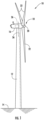
- FIG. 1 illustrates a perspective view of one embodiment of a wind turbine 10 according to the present disclosure.
- the wind turbine 10 includes a tower 12 extending from a support surface 14, a nacelle 16 mounted on the tower 12, and a rotor 18 coupled to the nacelle 16.
- the rotor 18 includes a rotatable hub 20 and at least one rotor blade 22 coupled to and extending outwardly from the hub 20.
- the rotor 18 includes three rotor blades 22.
- the rotor 18 may include more or less than three rotor blades 22.
- Each rotor blade 22 may be spaced about the hub 20 to facilitate rotating the rotor 18 to enable kinetic energy to be transferred from the wind into usable mechanical energy, and subsequently, electrical energy.
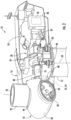
- the hub 20 may be rotatably coupled to drivetrain system 28 ( FIG. 2 ) positioned within the nacelle 16 to permit electrical energy to be produced.
- the drivetrain system 28 includes, at least, a generator 24 disposed within the nacelle 16.
- the generator 24 may be coupled to the rotor 18 of the wind turbine 10 for generating electrical power from the rotational energy generated by the rotor 18.
- the rotor 18 may include a main shaft 30 coupled to the hub 20 for rotation therewith.
- the generator 24 may then be coupled to the main shaft 30 such that rotation of the main shaft 30 drives the generator 24.
- the generator 24 includes a generator shaft 29 rotatably coupled to the main shaft 30 through a gearbox 34.
- the generator shaft 29 may be rotatably coupled directly to the main shaft 30.
- the generator 24 may be directly rotatably coupled to the main shaft 30.
- the main shaft 30 may generally be supported within the nacelle 16 by a support frame or bedplate 36 positioned atop the wind turbine tower 12.
- the wind turbine 10 may also include a turbine control system or a turbine controller 26 within the nacelle 16.
- the turbine controller 26 is disposed within a control cabinet 38 mounted to a portion of the nacelle 16.
- the turbine controller 26 may be disposed at any location on or in the wind turbine 10, at any location on the support surface 14 or generally at any other location.
- the turbine controller 26 may generally be configured to control the various operating modes (e.g., start-up or shut-down sequences) and/or components of the wind turbine 10.
- Each rotor blade 22 may also include a pitch adjustment mechanism 40 configured to rotate each rotor blade 22 about its pitch axis 42 via pitch bearing 44.
- the wind turbine 10 may include one or more yaw drive mechanisms 46 communicatively coupled to the controller 26, with each yaw drive mechanism(s) 46 being configured to change the angle of the nacelle 16 relative to the wind (e.g., by engaging a yaw bearing 48 of the wind turbine 10 to rotate the nacelle 16 about yaw axis 50).
- the wind turbine 10 may further include one or more sensors 52, 53, 54, 55.
- one or more first sensors 52, 54 may be used for monitoring movement of the main shaft 30 in one or more directions.
- Such first sensors may be, for example, proximity sensors positioned near the main shaft 30 for monitoring movement of the shaft 30 in one or more directions so as to detect damage of the main bearing 39 described herein.
- one or more second sensors 53, 55 may be configured for monitoring or measuring any suitable environmental and/or operating conditions that may affect lateral motion of the shaft 30, such as for example, a wind sensor 53 and/or an additional sensor 55 positioned within the nacelle 16 for monitoring various operating conditions of the drivetrain system 28.
- first and second sensors described herein 52, 53, 54, 55 may be any suitable sensor capable of monitoring movement of the main shaft 30 as well as any other shaft in the wind turbine 10.
- the wind turbine 10 may include any suitable number of sensors for monitoring such movement.
- the drivetrain system 28 includes, at least, the generator 24 and the gearbox 34.
- the generator 24 includes a generator rotor 25 and a generator stator 27.
- the generator rotor 25 is the rotating component of the generator 24, while the stator 27 is the stationary component of the generator 24.
- the generator 24 may be a doubly-fed induction generator (DFIG).
- DFIG doubly-fed induction generator
- the generator 24 according to the present disclosure is not limited to DFIG generators, and may include any generator suitable for powering the wind turbine 10 of the present disclosure.
- the rotor blades 16 rotate the generator rotor 25 of the generator 24.
- the generator rotor 25 may be operably connected to the hub 18. Accordingly, operation of the rotor blades 16 rotates the rotor hub 18, which rotates the generator rotor 25 and thus operates the generator 24.
- the low-speed main shaft 30 is configured to provide an input rotational speed to the gearbox 34.
- the hub 18 may be mounted to the main shaft 30.
- the main shaft 30 may include a main flange 41 configured to engage a mating flange (not shown) on the hub 18 to mount the hub 18 to the main shaft 30.
- the rotational speed of the rotor blades 16 may be directly transmitted through the hub 18 to the main shaft 30 as an input rotational speed.
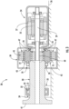
- the main shaft 30 may extend through and be supported by at least one support housing 35 or a plurality of support housings 35.
- a first housing 35 and, in some embodiments, a second housing (not shown), may be provided to support the main shaft 30.
- the housing(s) 35 may include one or more main bearings 39 configured to interact with the main shaft 30.
- the housing(s) 35 may include a locating bearing 39 (also referred to herein as a main shaft bearing 39) configured therein, while the second housing may include a floating bearing (not shown) configured therein.
- the main shaft bearing(s) 39 may include an inner race 31, an outer race 32, and a plurality roller elements 33 configured therebetween.
- the gearbox 34 as described herein may be a planetary gearbox 34.
- the gearbox 34 may be configured to convert the input rotational speed from the main shaft 30 to an output rotational speed.
- the output rotational speed may be faster than the input rotational speed.
- the output rotational speed may be slower than the input rotational speed.
- the gearbox 34 may be a single stage gearbox.
- the input rotational speed may be converted to the output rotational speed through a single stage of various mating gears, as discussed below.
- the gearbox 34 may be a multiple stage gearbox, and the input rotational speed may be converted to the output rotational speed through multiple stages of various mating gears.
- the illustrated embodiment of the planetary gearbox 34 includes a stationary ring gear 45 and a plurality of rotatable gears.
- the stationary ring gear 45 supports the various rotatable gears configured therein.
- the stationary ring gear 45 includes various axes for the rotatable gears to rotate about.
- the planetary gearbox 34 may also include a stationary ring gear 45, one or more rotatable planetary gears 47, and a rotatable sun gear 49.
- the planetary gearbox 34 may include four planetary gears 47. However, it should be understood that more or less than four planetary gears 47 are within the scope and spirit of the present disclosure.
- each of the rotatable gears in the planetary gearbox 34 includes a plurality of gear teeth (not shown). As such, the teeth may mesh together such that the various gears 45, 47, 49 engage each other.
- the carrier 43 may drive the planetary gearbox 34.
- the carrier 43 and the main shaft 30 may be coupled such that the input rotational speed of the main shaft 30 is provided to the carrier 43.
- a gearbox disk may connect the carrier 43 and main shaft 30, or the carrier 43 and main shaft 30 may be otherwise suitably connected.
- the ring gear 45 or the sun gear 49 may drive the planetary gearbox 34.
- the drivetrain system 28 of the present disclosure may further include an output or generator shaft 29. More specifically, as shown, the generator shaft 29 may be coupled with the gearbox 34, and configured to rotate at the output rotational speed.
- the generator shaft 29 may be the sun gear 49.
- the sun gear 49 may engage the planetary gears 47 and may further extend from the planetary gearbox 34 towards the generator 24.
- the generator shaft 29 may be coupled to the sun gear 49 or other output gear of the planetary gearbox 34 or other suitable gearbox such that the generator shaft 29 may rotate at the output rotational speed.
- various bearings 39, 70, 72 may surround the various rotatable components of the drivetrain system 28 to facilitate relatively efficient rotation of such rotatable components.
- a plurality of carrier bearings 70 may surround the planetary carrier 43 and a plurality of planet bearings 72 may surround the planetary gears 47 and/or additional bearings which support the sun gear or sun gear shaft (not shown).
- Such bearings 70, 72 may be roller bearings, and include various roller elements arranged in generally annular arrays, or may be journal bearings or any other suitable bearings.
- the bearings 39, 70, 72 as described herein may also be referred to as low-speed bearings.
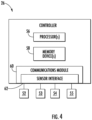
- the controller 26 may include one or more processor(s) 56 and associated memory device(s) 58 configured to perform a variety of computer-implemented functions (e.g., performing the methods, steps, calculations and the like and storing relevant data as disclosed herein). Additionally, the controller 26 may also include a communications module 60 to facilitate communications between the controller 26 and the various components of the wind turbine 10.
- the communications module 60 may include a sensor interface 62 (e.g., one or more analog-to-digital converters) to permit signals transmitted from the sensors 52, 53, 54, 55 to be converted into signals that can be understood and processed by the processors 56.
- the sensors 52, 53, 54, 55 may be communicatively coupled to the communications module 64 using any suitable means.
- the sensors 52, 53, 54, 55 are coupled to the sensor interface 62 via a wired connection.
- the sensors 52, 53, 54, 55 may be coupled to the sensor interface 62 via a wireless connection, such as by using any suitable wireless communications protocol known in the art.
- the sensors 52, 53, 54, 55 may also be coupled to a separate controller that may or may not be located in the control cabinet 38. As such, the sensors 52, 53, 54, 55 may provide related information to the turbine controller 26 and/or the separate controller. It should also be appreciated that, as used herein, the term "monitor" and variations thereof indicates that the various sensors of the wind turbine 10 may be configured to provide a direct measurement of the parameters being monitored and/or an indirect measurement of such parameters. Thus, the sensors 52, 53, 54, 55 described herein may, for example, be used to generate signals relating to the parameter being monitored, which can then be utilized by the controller 26 to determine the condition.
- the term "processor” refers not only to integrated circuits referred to in the art as being included in a computer, but also refers to a controller, a microcontroller, a microcomputer, a programmable logic controller (PLC), an application specific integrated circuit, and other programmable circuits.
- the memory device(s) 58 may generally comprise memory element(s) including, but not limited to, computer readable medium (e.g., random access memory (RAM)), computer readable non-volatile medium (e.g., a flash memory), a floppy disk, a compact disc-read only memory (CD-ROM), a magneto-optical disk (MOD), a digital versatile disc (DVD) and/or other suitable memory elements.
- RAM random access memory
- CD-ROM compact disc-read only memory
- MOD magneto-optical disk
- DVD digital versatile disc
- Such memory device(s) 58 may generally be configured to store suitable computer-readable instructions that, when implemented by the processor(s) 56, configure the controller 26 to perform various functions including, but not limited to, transmitting suitable control signals to implement corrective action(s) in response to a distance signal exceeding a predetermined threshold as described herein, as well as various other suitable computer-implemented functions.
- the turbine controller 26 (or any separate controller or computing system integral with or remote from the turbine controller 26) is further configured to implement an algorithm for detecting damage in a bearing coupled to a rotating shaft of a rotary machine, such as the wind turbine 10.
- the method 100 described herein generally applies to the wind turbine 10 described above.
- the disclosed method 100 may be implemented using any other suitable rotary machine having a rotating shaft and associated bearing.
- FIG. 5 depicts steps performed in a particular order for purposes of illustration and discussion. Those of ordinary skill in the art, using the disclosures provided herein, will understand that various steps of any of the methods disclosed herein can be adapted, omitted, rearranged, or expanded in various ways without deviating from the scope of the present disclosure.
- the method 100 includes receiving one or more measurement signals from the first sensor(s) 52, 54 for monitoring movement of the main shaft 30 in one or more directions over a time period.
- the direction may include lateral direction with respect to a longitudinal direction of the main shaft 30.
- the method 100 may also include monitoring various environmental and/or operating conditions of the wind turbine 10 via the second sensor(s) 53, 55.
- the method 100 includes removing an effect of one or more environmental and/or operating conditions of the wind turbine 10 from the one or more measurement signals over the time period.
- a controller may automatically and adaptively learn the effect of one or more environmental and/or operating conditions on the movement of the main shaft 30, e.g. by monitoring the environmental and/or operating conditions via second sensors 53, 55.
- the training period can include any suitable time period, for example, range from 1 day to 50 days, such as 28, 29, 30, or 31 days as shown.
- the environmental and/or operating conditions may include, for example, wind speed, wind direction, wind gust, wind shear, temperature, time of day, air density, generator speed, rotor speed, power output, thrust, and/or torque.
- the controller is configured to remove the effect of the environmental and/or operating condition(s) of the wind turbine 10 from the one or more measurement signals by automatically and adaptively eliminating the effect of one or more environmental and/or operating conditions on the movement of the rotating shaft 30 from the measurement signal(s) (i.e. data from sensors 53, 55).
- the controller can automatically and adaptively eliminate the effect of one or more environmental and/or operating conditions on the movement of the rotating shaft 30 from the measurement signal(s), i.e. by computing a corrected measurement signal.
- the method 100 may include automatically and adaptively learning and eliminating the effect of the environmental and/or operating conditions (e.g. input variables 150) on the movement of the main shaft 30 via a machine learning regression model 160.
- the machine learning regression model 160 may utilize at least one of linear regression, non-linear regression, support vector regression, gradient boosting regression, decision tree regression, random forest regression, generalized linear models, kernel regression, or a neural network.
- the controller is configured to removing the effect of the environmental and/or operating condition(s) of the wind turbine 10 from the one or more measurement signals over the time period by determining a predicted measurement signal 154 of the sensor(s) via the regression model 160. Further, as shown at 158, the controller is configured to subtract the predicted measurement signal 154 from an original measurement signal 152 of the measurement signal(s) to obtain a corrected measurement signal 156 using e.g. via Equation (2).
- the method 100 includes analyzing changes in the measurement signal(s), wherein changes in the measurement signal(s) above a predetermined threshold or of a certain magnitude are indicative of a damaged bearing (e.g. a damaged main bearing 39).
- the changes or variations in the measurement signal(s) may be decreases in the measurement signal(s).
- the controller is configured to analyze the changes/variations in the measurement signal(s) by comparing the corrected measurement signal to the predetermined threshold or by determining whether variations in the corrected measurement signal are of the certain magnitude. In the latter example, a high-degree of variation in the corrected measurement signal can be indicative that the measurement signal is no longer accurately predicted by the operation and environmental signals.
- the method 100 includes implementing a corrective action when the changes/variations in the measurement signal(s) are above the predetermined threshold or are of the certain magnitude.
- the corrective action may include any suitable action short of shutting down the wind turbine 10, such as for example generating an alarm, scheduling a maintenance and/or repair procedure.
- FIG. 8A illustrates a graph 200 of raw proximity sensor measurement data (y-axis) versus time (x-axis)
- FIG. 8B illustrates a graph 300 of corrected proximity sensor measurement data (y-axis) versus time (x-axis).
- circled areas 202 and 302 there is a significant reduction in the root square mean deviation of the after elimination of the system variations.
- circled areas 204 and 304 the data provides clearer and earlier detection of bearing faults.
Landscapes
- Engineering & Computer Science (AREA)
- General Engineering & Computer Science (AREA)
- Mechanical Engineering (AREA)
- Life Sciences & Earth Sciences (AREA)
- Sustainable Development (AREA)
- Sustainable Energy (AREA)
- Chemical & Material Sciences (AREA)
- Combustion & Propulsion (AREA)
- Physics & Mathematics (AREA)
- General Physics & Mathematics (AREA)
- Wind Motors (AREA)
Claims (14)
- Procédé (100) de détection de dommages dans un palier accouplé à un arbre rotatif (30) d'une machine rotative, le procédé (100) comprenant :la réception d'un ou plusieurs signaux de mesure à partir d'un ou plusieurs premiers capteurs (52, 54) pour surveiller le mouvement de l'arbre rotatif dans une ou plusieurs directions sur une période de temps (102) ;l'élimination d'un effet d'une ou plusieurs conditions environnementales et/ou de fonctionnement de la machine rotative à partir du ou des signaux de mesure sur la période de temps (104), l'élimination d'un effet d'une ou plusieurs conditions environnementales et/ou de fonctionnement de la machine rotative à partir du ou des signaux de mesure sur la période de temps (104) comprenant la détermination d'un signal de mesure prédit (154) du ou des premiers capteurs (52, 54) par l'intermédiaire du modèle de régression (160) ; et, la soustraction du signal de mesure prédit (154) d'un signal de mesure d'origine (152) du ou des signaux de mesure pour obtenir un signal de mesure corrigé (156) ;après élimination, l'analyse des changements dans le ou les signaux de mesure provenant du ou des premiers capteurs (52, 54), dans lequel des changements dans le ou les signaux de mesure au-dessus d'un seuil prédéterminé ou d'une certaine amplitude indiquent un palier endommagé (106) ; etla mise en oeuvre d'une action corrective lorsque les changements dans le ou les signaux de mesure sont supérieurs au seuil prédéterminé (108).
- Procédé (100) selon la revendication 1, dans lequel les changements dans le ou les signaux de mesure comprennent des diminutions dans le ou les signaux de mesure.
- Procédé (100) selon l'une quelconque des revendications précédentes, comprenant en outre la surveillance, par l'intermédiaire d'un ou plusieurs seconds capteurs (53, 55), de la ou des conditions environnementales et/ou de fonctionnement de la machine rotative ; et
l'apprentissage automatique et adaptatif de l'effet de la ou des conditions environnementales et/ou de fonctionnement sur le mouvement de l'arbre rotatif (30) à partir du ou des signaux de mesure. - Procédé (100) selon l'une quelconque des revendications précédentes, dans lequel l'élimination de l'effet de la ou des conditions environnementales et/ou de fonctionnement de la machine rotative à partir du ou des signaux de mesure sur la période de temps comprend en outre :
l'élimination automatique et adaptative de l'effet de la ou des conditions environnementales et/ou de fonctionnement sur le mouvement de l'arbre rotatif (30) à partir du ou des signaux de mesure. - Procédé (100) selon l'une quelconque des revendications précédentes, comprenant en outre l'apprentissage automatique et adaptatif et l'élimination automatique et adaptative de l'effet des conditions environnementales et/ou de fonctionnement de mouvement de l'arbre rotatif (30) par l'intermédiaire d'un modèle de régression d'apprentissage automatique.
- Procédé (100) selon l'une quelconque des revendications précédentes, dans lequel le modèle de régression d'apprentissage automatique (160) utilise au moins l'un parmi une régression linéaire, une régression non linéaire, une régression vectorielle de support, une régression d'amplification de gradient, une régression d'arbre de décision, une régression de forêt aléatoire, des modèles linéaires généralisés, une régression de noyau, ou un réseau neuronal.
- Procédé (100) selon l'une quelconque des revendications précédentes, dans lequel l'analyse des changements dans le ou les signaux de mesure comprend en outre la comparaison du signal de mesure corrigé (156) au seuil prédéterminé ou la détermination du fait de savoir si des variations dans le signal de mesure corrigé (156) sont de la certaine amplitude.
- Procédé (100) selon l'une quelconque des revendications précédentes, dans lequel la machine rotative comprend une éolienne (10), l'arbre rotatif comprend un arbre principal (30) de l'éolienne (10), et le palier comprend un palier principal (39) de l'éolienne (10).
- Procédé (100) selon l'une quelconque des revendications précédentes, dans lequel les conditions environnementales et/ou de fonctionnement comprennent au moins l'un parmi la vitesse du vent, la direction du vent, la rafale de vent, le cisaillement du vent, la température, l'heure de la journée, la densité d'air, la vitesse du générateur, la vitesse du rotor, la sortie de puissance, la poussée ou le couple.
- Procédé (100) selon l'une quelconque des revendications précédentes, dans lequel le ou les premiers capteurs (52, 54) comprennent un ou plusieurs capteurs de proximité.
- Procédé (100) selon l'une quelconque des revendications précédentes, dans lequel la ou les directions comprennent, au moins, une direction latérale par rapport à une direction longitudinale de l'arbre rotatif (30).
- Procédé (100) selon l'une quelconque des revendications précédentes, dans lequel la mise en oeuvre de l'action corrective comprend en outre au moins l'une parmi la génération d'une alarme ou la planification d'une procédure de maintenance et/ou de réparation.
- Système de détection de dommages dans un palier principal (39) accouplé à un arbre principal (30) d'une éolienne (10), le système comprenant :un ou plusieurs premiers capteurs (52, 54) pour surveiller le mouvement de l'arbre principal (30) dans une ou plusieurs directions ;un ou plusieurs seconds capteurs (53, 55) pour surveiller une ou plusieurs conditions environnementales et/ou de fonctionnement de l'éolienne (10) ; etun dispositif de commande (26) couplé en communication au ou aux premier (52, 54) et second capteurs (53, 55), le dispositif de commande (26) étant configuré pour effectuer une pluralité d'opérations, la pluralité d'opérations comprenant :la réception d'un ou plusieurs signaux de mesure provenant du ou des premiers capteurs (52, 54) sur une période de temps (102) ;l'élimination d'un effet d'une ou plusieurs conditions environnementales et/ou de fonctionnement de l'éolienne (10) du ou des signaux de mesure sur la période de temps (104), l'élimination d'un effet d'une ou plusieurs conditions environnementales et/ou de fonctionnement de la machine rotative à partir du ou des signaux de mesure sur la période de temps (104) comprenant en outre la détermination d'un signal de mesure prédit (154) du ou des premiers capteurs (52, 54) par l'intermédiaire du modèle de régression (160) ; et, la soustraction du signal de mesure prédit (154) d'un signal de mesure d'origine (152) du ou des signaux de mesure pour obtenir un signal de mesure corrigé (156) ;l'analyse de la diminution dans le ou les signaux de mesure provenant du ou des premiers capteurs (52, 54), dans lequel la diminution du ou des signaux de mesure au-dessus d'un seuil prédéterminé ou d'une certaine amplitude indique un palier principal endommagé (39) (106) ; et,la mise en oeuvre d'une action corrective lorsque les diminutions dans le ou les signaux de mesure sont supérieures au seuil prédéterminé (108).
- Système selon la revendication 13, dans lequel la pluralité d'opérations comprend en outre l'apprentissage automatique et adaptatif de l'effet de la ou des conditions environnementales et/ou de fonctionnement sur le mouvement de l'arbre principal (30) à partir du ou des signaux de mesure.
Applications Claiming Priority (1)
| Application Number | Priority Date | Filing Date | Title |
|---|---|---|---|
| IN201911030887 | 2019-07-31 |
Publications (3)
| Publication Number | Publication Date |
|---|---|
| EP3771823A1 EP3771823A1 (fr) | 2021-02-03 |
| EP3771823B1 true EP3771823B1 (fr) | 2023-11-08 |
| EP3771823B8 EP3771823B8 (fr) | 2023-12-20 |
Family
ID=71899642
Family Applications (1)
| Application Number | Title | Priority Date | Filing Date |
|---|---|---|---|
| EP20189001.9A Active EP3771823B8 (fr) | 2019-07-31 | 2020-07-31 | Systèmes et procédés de détection de dommages dans des machines rotatives |
Country Status (5)
| Country | Link |
|---|---|
| US (1) | US11460006B2 (fr) |
| EP (1) | EP3771823B8 (fr) |
| CN (1) | CN112302885B (fr) |
| DK (1) | DK3771823T3 (fr) |
| ES (1) | ES2972401T3 (fr) |
Families Citing this family (5)
| Publication number | Priority date | Publication date | Assignee | Title |
|---|---|---|---|---|
| EP3951167B1 (fr) * | 2019-03-28 | 2024-01-31 | NTN Corporation | Système de surveillance d'état |
| CN113503232A (zh) * | 2021-08-20 | 2021-10-15 | 西安热工研究院有限公司 | 一种风机运行健康状态预警方法及系统 |
| CN115717992B (zh) * | 2022-11-18 | 2026-01-02 | 盐城工学院 | 一种基于多粒度扫描和catboost模型的轴承故障诊断方法 |
| EP4481359B1 (fr) * | 2023-05-09 | 2026-02-11 | Shandong Golden Empire Precision Machinery Technology Co., Ltd | Procédé et dispositif de surveillance de fonctionnement pour porte-palier d'éolienne |
| EP4679052A1 (fr) * | 2024-07-12 | 2026-01-14 | Siemens Gamesa Renewable Energy A/S | Dispositif de surveillance d'état |
Family Cites Families (34)
| Publication number | Priority date | Publication date | Assignee | Title |
|---|---|---|---|---|
| JP2002340922A (ja) * | 2001-01-25 | 2002-11-27 | Nsk Ltd | 車輪用回転検出装置 |
| EP1548419B1 (fr) | 2002-08-30 | 2013-07-24 | NSK Ltd. | Procede et dispositif de controle d'etat de materiel mecanique et dispositif de diagnostic d'anomalies |
| WO2006030786A1 (fr) | 2004-09-13 | 2006-03-23 | Nsk Ltd. | Dispositif de diagnostic d’anomalie et procede de diagnostic d’anomalie |
| DE602007001981D1 (de) | 2007-10-12 | 2009-09-24 | Siemens Ag | Verfahren und Vorrichtung zur Bereitstellung mindestens eines Eingangssensorsignals für eine Steuerungs- und/oder Überwachungsanwendung sowie Steuerungsvorrichtung |
| EP2373971B1 (fr) | 2008-12-22 | 2022-01-26 | S.P.M. Instrument AB | Système d'analyse |
| US8812265B2 (en) | 2008-12-22 | 2014-08-19 | S.P.M. Instrument Ab | Analysis system |
| JP5725833B2 (ja) | 2010-01-04 | 2015-05-27 | Ntn株式会社 | 転がり軸受の異常診断装置、風力発電装置および異常診断システム |
| JP5562274B2 (ja) | 2010-03-12 | 2014-07-30 | Ntn株式会社 | 摩耗検知装置およびそれを備える風力発電装置ならびに摩耗検知方法 |
| JP5534875B2 (ja) | 2010-03-12 | 2014-07-02 | Ntn株式会社 | 軸受のスミアリング損傷防止装置および軸受のスミアリング損傷防止方法 |
| SE534531C2 (sv) | 2010-03-30 | 2011-09-20 | Rubico Ab | Metod för feldetektion av rullningslager genom förhöjning av statistisk asymmetri |
| US9574570B2 (en) * | 2010-11-03 | 2017-02-21 | Hamilton Sundstard Corporation | Shaft speed and vibration sensor apparatus |
| US8099255B2 (en) * | 2010-12-16 | 2012-01-17 | General Electric Company | System and method for measuring shaft deflection in a wind turbine |
| PT2710438T (pt) | 2011-05-20 | 2022-04-20 | Insight Analytics Solutions Holdings Ltd | Determinação de danos e de vida útil restante de mecanismos rotativos, incluindo unidades de tracção, caixas de engrenagens e geradores |
| DK2626683T3 (da) | 2012-02-07 | 2014-09-08 | Siemens Ag | Vindmølle, omfattende et antal af lejer |
| JP6196093B2 (ja) | 2012-12-25 | 2017-09-13 | Ntn株式会社 | 軸受装置の振動解析方法、軸受装置の振動解析装置、および転がり軸受の状態監視装置 |
| CN103176128A (zh) | 2013-03-28 | 2013-06-26 | 华南理工大学 | 一种风力发电机组状态预报及智能故障诊断方法及系统 |
| US10677685B2 (en) | 2013-04-05 | 2020-06-09 | Aktiebolaget Skf | Method, computer program product and system |
| CN103411774B (zh) | 2013-07-17 | 2016-12-28 | 华北电力大学 | 波动工况下的风电机组在线预警方法 |
| CN103940608B (zh) | 2014-04-29 | 2016-10-19 | 中能电力科技开发有限公司 | 一种提高风电机组齿轮箱故障等级判断精度的方法 |
| US10047726B2 (en) * | 2014-07-29 | 2018-08-14 | Ntn Corporation | Condition monitoring system and wind power generation system comprising the same |
| JP5943357B2 (ja) | 2014-09-17 | 2016-07-05 | インターナショナル・ビジネス・マシーンズ・コーポレーションInternational Business Machines Corporation | 検出装置、検出方法、およびプログラム |
| JP6308922B2 (ja) * | 2014-09-17 | 2018-04-11 | Ntn株式会社 | 転がり軸受の異常診断装置、風力発電装置、及び転がり軸受の異常診断方法 |
| US10883475B2 (en) * | 2015-11-26 | 2021-01-05 | Vestas Wind Systems A/S | Method for monitoring and assessing power performance changes of a wind turbine |
| CN108603491B (zh) | 2016-02-12 | 2021-02-09 | 维斯塔斯风力系统集团公司 | 一种控制风力涡轮机轴承磨损的方法、风力涡轮机以及计算机程序产品 |
| CN108780025B (zh) | 2016-03-17 | 2021-07-23 | Ntn株式会社 | 状态监视系统和风力发电装置 |
| EP3452530B1 (fr) | 2016-05-04 | 2020-09-30 | Covestro Intellectual Property GmbH & Co. KG | Copolycarbonate en tant que materiau support pour l'impression en 3d |
| US10852214B2 (en) | 2017-05-19 | 2020-12-01 | Nutech Ventures | Detecting faults in wind turbines |
| US10495693B2 (en) | 2017-06-01 | 2019-12-03 | General Electric Company | Wind turbine fault detection using acoustic, vibration, and electrical signals |
| JP7013787B2 (ja) | 2017-10-19 | 2022-02-01 | 日本精工株式会社 | 風力発電用風車の状態監視装置、状態監視方法、及び状態監視システム |
| CN208021323U (zh) | 2018-03-26 | 2018-10-30 | 苏州车萝卜汽车电子科技有限公司 | 用于汽车a柱的显示装置、汽车 |
| CN108331718B (zh) * | 2018-04-10 | 2024-03-12 | 国电联合动力技术有限公司 | 风电机组偏航系统在线监测机构及故障诊断系统和方法 |
| CN109187021B (zh) | 2018-07-26 | 2019-10-01 | 河海大学 | 基于熵的多源风电机组轴承故障诊断方法 |
| CN108896312A (zh) | 2018-08-08 | 2018-11-27 | 国电联合动力技术有限公司 | 一种风电主轴承故障预测和寿命评估系统及方法 |
| CN109239598A (zh) | 2018-09-30 | 2019-01-18 | 中船重工电机科技股份有限公司 | 轴承电蚀风力发电机结构缺陷检测机构及检测方法 |
-
2020
- 2020-07-28 US US16/940,753 patent/US11460006B2/en active Active
- 2020-07-31 ES ES20189001T patent/ES2972401T3/es active Active
- 2020-07-31 EP EP20189001.9A patent/EP3771823B8/fr active Active
- 2020-07-31 DK DK20189001.9T patent/DK3771823T3/da active
- 2020-07-31 CN CN202010757663.3A patent/CN112302885B/zh active Active
Also Published As
| Publication number | Publication date |
|---|---|
| EP3771823B8 (fr) | 2023-12-20 |
| ES2972401T3 (es) | 2024-06-12 |
| US20210033074A1 (en) | 2021-02-04 |
| CN112302885A (zh) | 2021-02-02 |
| EP3771823A1 (fr) | 2021-02-03 |
| US11460006B2 (en) | 2022-10-04 |
| CN112302885B (zh) | 2025-10-21 |
| DK3771823T3 (da) | 2024-02-05 |
Similar Documents
| Publication | Publication Date | Title |
|---|---|---|
| EP3771823B1 (fr) | Systèmes et procédés de détection de dommages dans des machines rotatives | |
| EP3421786B1 (fr) | Systèmes et procédé de détection de dommages dans des paliers d'éoliennes | |
| EP3581795B1 (fr) | Système et procédé de commande d'éolienne pour minimiser les dommages de pales de rotor | |
| CN114787505B (zh) | 用于监测风力涡轮的转子叶片健康的系统和方法 | |
| EP4051898B1 (fr) | Système et procédé de prévention des défaillances d'articulations de pas dans une éolienne à l'aide de signaux de moteur de pas | |
| EP3702613B1 (fr) | Système et procédé de prédiction d'arrêts d'éolienne en raison de vibrations excessives | |
| CN114945750A (zh) | 用于控制风力涡轮的系统和方法 | |
| EP3444576B1 (fr) | Systèmes et procédés de détection de dommages dans des machines rotatives | |
| CN111810357B (zh) | 用于减轻风力涡轮的转子叶片的损坏的系统及方法 | |
| EP3722597B1 (fr) | Système et procédé pour prévenir les dommages catastrophiques dans une transmission d'une éolienne | |
| US12078148B2 (en) | System and method for detecting anomalies in wind turbine control signals | |
| US12234808B2 (en) | System and method for scheduling preventative maintenance actions based on operational usage | |
| US12607163B2 (en) | System and method for detecting and responding to rotor blade damage in a wind turbine |
Legal Events
| Date | Code | Title | Description |
|---|---|---|---|
| PUAI | Public reference made under article 153(3) epc to a published international application that has entered the european phase |
Free format text: ORIGINAL CODE: 0009012 |
|
| STAA | Information on the status of an ep patent application or granted ep patent |
Free format text: STATUS: THE APPLICATION HAS BEEN PUBLISHED |
|
| AK | Designated contracting states |
Kind code of ref document: A1 Designated state(s): AL AT BE BG CH CY CZ DE DK EE ES FI FR GB GR HR HU IE IS IT LI LT LU LV MC MK MT NL NO PL PT RO RS SE SI SK SM TR |
|
| AX | Request for extension of the european patent |
Extension state: BA ME |
|
| STAA | Information on the status of an ep patent application or granted ep patent |
Free format text: STATUS: REQUEST FOR EXAMINATION WAS MADE |
|
| 17P | Request for examination filed |
Effective date: 20210729 |
|
| RBV | Designated contracting states (corrected) |
Designated state(s): AL AT BE BG CH CY CZ DE DK EE ES FI FR GB GR HR HU IE IS IT LI LT LU LV MC MK MT NL NO PL PT RO RS SE SI SK SM TR |
|
| STAA | Information on the status of an ep patent application or granted ep patent |
Free format text: STATUS: EXAMINATION IS IN PROGRESS |
|
| 17Q | First examination report despatched |
Effective date: 20220421 |
|
| GRAP | Despatch of communication of intention to grant a patent |
Free format text: ORIGINAL CODE: EPIDOSNIGR1 |
|
| STAA | Information on the status of an ep patent application or granted ep patent |
Free format text: STATUS: GRANT OF PATENT IS INTENDED |
|
| INTG | Intention to grant announced |
Effective date: 20230519 |
|
| P01 | Opt-out of the competence of the unified patent court (upc) registered |
Effective date: 20230530 |
|
| GRAS | Grant fee paid |
Free format text: ORIGINAL CODE: EPIDOSNIGR3 |
|
| GRAA | (expected) grant |
Free format text: ORIGINAL CODE: 0009210 |
|
| STAA | Information on the status of an ep patent application or granted ep patent |
Free format text: STATUS: THE PATENT HAS BEEN GRANTED |
|
| AK | Designated contracting states |
Kind code of ref document: B1 Designated state(s): AL AT BE BG CH CY CZ DE DK EE ES FI FR GB GR HR HU IE IS IT LI LT LU LV MC MK MT NL NO PL PT RO RS SE SI SK SM TR |
|
| REG | Reference to a national code |
Ref country code: GB Ref legal event code: FG4D |
|
| REG | Reference to a national code |
Ref country code: CH Ref legal event code: EP |
|
| REG | Reference to a national code |
Ref country code: DE Ref legal event code: R081 Ref document number: 602020020595 Country of ref document: DE Owner name: GENERAL ELECTRIC RENOVABLES ESPANA S.L., ES Free format text: FORMER OWNER: GENERAL ELECTRIC COMPANY, SCHENECTADY, NY, US Ref country code: DE Ref legal event code: R081 Ref document number: 602020020595 Country of ref document: DE Owner name: GENERAL ELECTRIC RENOVABLES ESPAIIA, S.L., ES Free format text: FORMER OWNER: GENERAL ELECTRIC COMPANY, SCHENECTADY, NY, US |
|
| REG | Reference to a national code |
Ref country code: CH Ref legal event code: PK Free format text: BERICHTIGUNG B8 Ref country code: DE Ref legal event code: R096 Ref document number: 602020020595 Country of ref document: DE |
|
| REG | Reference to a national code |
Ref country code: IE Ref legal event code: FG4D |
|
| REG | Reference to a national code |
Ref country code: DE Ref legal event code: R081 Ref document number: 602020020595 Country of ref document: DE Owner name: GENERAL ELECTRIC RENOVABLES ESPANA S.L., ES Free format text: FORMER OWNER: GENERAL ELECTRIC RENOVABLES ESPAIIA, S.L., BARCELONA, ES |
|
| RAP2 | Party data changed (patent owner data changed or rights of a patent transferred) |
Owner name: GENERAL ELECTRIC RENOVABLES ESPANA, S.L. |
|
| REG | Reference to a national code |
Ref country code: DK Ref legal event code: T3 Effective date: 20240202 |
|
| REG | Reference to a national code |
Ref country code: LT Ref legal event code: MG9D |
|
| REG | Reference to a national code |
Ref country code: NL Ref legal event code: MP Effective date: 20231108 |
|
| PG25 | Lapsed in a contracting state [announced via postgrant information from national office to epo] |
Ref country code: GR Free format text: LAPSE BECAUSE OF FAILURE TO SUBMIT A TRANSLATION OF THE DESCRIPTION OR TO PAY THE FEE WITHIN THE PRESCRIBED TIME-LIMIT Effective date: 20240209 |
|
| PG25 | Lapsed in a contracting state [announced via postgrant information from national office to epo] |
Ref country code: IS Free format text: LAPSE BECAUSE OF FAILURE TO SUBMIT A TRANSLATION OF THE DESCRIPTION OR TO PAY THE FEE WITHIN THE PRESCRIBED TIME-LIMIT Effective date: 20240308 |
|
| PG25 | Lapsed in a contracting state [announced via postgrant information from national office to epo] |
Ref country code: LT Free format text: LAPSE BECAUSE OF FAILURE TO SUBMIT A TRANSLATION OF THE DESCRIPTION OR TO PAY THE FEE WITHIN THE PRESCRIBED TIME-LIMIT Effective date: 20231108 |
|
| REG | Reference to a national code |
Ref country code: AT Ref legal event code: MK05 Ref document number: 1629819 Country of ref document: AT Kind code of ref document: T Effective date: 20231108 |
|
| PG25 | Lapsed in a contracting state [announced via postgrant information from national office to epo] |
Ref country code: NL Free format text: LAPSE BECAUSE OF FAILURE TO SUBMIT A TRANSLATION OF THE DESCRIPTION OR TO PAY THE FEE WITHIN THE PRESCRIBED TIME-LIMIT Effective date: 20231108 |
|
| PG25 | Lapsed in a contracting state [announced via postgrant information from national office to epo] |
Ref country code: AT Free format text: LAPSE BECAUSE OF FAILURE TO SUBMIT A TRANSLATION OF THE DESCRIPTION OR TO PAY THE FEE WITHIN THE PRESCRIBED TIME-LIMIT Effective date: 20231108 |
|
| PG25 | Lapsed in a contracting state [announced via postgrant information from national office to epo] |
Ref country code: NL Free format text: LAPSE BECAUSE OF FAILURE TO SUBMIT A TRANSLATION OF THE DESCRIPTION OR TO PAY THE FEE WITHIN THE PRESCRIBED TIME-LIMIT Effective date: 20231108 Ref country code: LT Free format text: LAPSE BECAUSE OF FAILURE TO SUBMIT A TRANSLATION OF THE DESCRIPTION OR TO PAY THE FEE WITHIN THE PRESCRIBED TIME-LIMIT Effective date: 20231108 Ref country code: IS Free format text: LAPSE BECAUSE OF FAILURE TO SUBMIT A TRANSLATION OF THE DESCRIPTION OR TO PAY THE FEE WITHIN THE PRESCRIBED TIME-LIMIT Effective date: 20240308 Ref country code: GR Free format text: LAPSE BECAUSE OF FAILURE TO SUBMIT A TRANSLATION OF THE DESCRIPTION OR TO PAY THE FEE WITHIN THE PRESCRIBED TIME-LIMIT Effective date: 20240209 Ref country code: BG Free format text: LAPSE BECAUSE OF FAILURE TO SUBMIT A TRANSLATION OF THE DESCRIPTION OR TO PAY THE FEE WITHIN THE PRESCRIBED TIME-LIMIT Effective date: 20240208 Ref country code: AT Free format text: LAPSE BECAUSE OF FAILURE TO SUBMIT A TRANSLATION OF THE DESCRIPTION OR TO PAY THE FEE WITHIN THE PRESCRIBED TIME-LIMIT Effective date: 20231108 Ref country code: PT Free format text: LAPSE BECAUSE OF FAILURE TO SUBMIT A TRANSLATION OF THE DESCRIPTION OR TO PAY THE FEE WITHIN THE PRESCRIBED TIME-LIMIT Effective date: 20240308 |
|
| PG25 | Lapsed in a contracting state [announced via postgrant information from national office to epo] |
Ref country code: SE Free format text: LAPSE BECAUSE OF FAILURE TO SUBMIT A TRANSLATION OF THE DESCRIPTION OR TO PAY THE FEE WITHIN THE PRESCRIBED TIME-LIMIT Effective date: 20231108 Ref country code: RS Free format text: LAPSE BECAUSE OF FAILURE TO SUBMIT A TRANSLATION OF THE DESCRIPTION OR TO PAY THE FEE WITHIN THE PRESCRIBED TIME-LIMIT Effective date: 20231108 Ref country code: PL Free format text: LAPSE BECAUSE OF FAILURE TO SUBMIT A TRANSLATION OF THE DESCRIPTION OR TO PAY THE FEE WITHIN THE PRESCRIBED TIME-LIMIT Effective date: 20231108 Ref country code: NO Free format text: LAPSE BECAUSE OF FAILURE TO SUBMIT A TRANSLATION OF THE DESCRIPTION OR TO PAY THE FEE WITHIN THE PRESCRIBED TIME-LIMIT Effective date: 20240208 Ref country code: LV Free format text: LAPSE BECAUSE OF FAILURE TO SUBMIT A TRANSLATION OF THE DESCRIPTION OR TO PAY THE FEE WITHIN THE PRESCRIBED TIME-LIMIT Effective date: 20231108 Ref country code: HR Free format text: LAPSE BECAUSE OF FAILURE TO SUBMIT A TRANSLATION OF THE DESCRIPTION OR TO PAY THE FEE WITHIN THE PRESCRIBED TIME-LIMIT Effective date: 20231108 |
|
| REG | Reference to a national code |
Ref country code: ES Ref legal event code: FG2A Ref document number: 2972401 Country of ref document: ES Kind code of ref document: T3 Effective date: 20240612 |
|
| PG25 | Lapsed in a contracting state [announced via postgrant information from national office to epo] |
Ref country code: CZ Free format text: LAPSE BECAUSE OF FAILURE TO SUBMIT A TRANSLATION OF THE DESCRIPTION OR TO PAY THE FEE WITHIN THE PRESCRIBED TIME-LIMIT Effective date: 20231108 |
|
| PG25 | Lapsed in a contracting state [announced via postgrant information from national office to epo] |
Ref country code: SK Free format text: LAPSE BECAUSE OF FAILURE TO SUBMIT A TRANSLATION OF THE DESCRIPTION OR TO PAY THE FEE WITHIN THE PRESCRIBED TIME-LIMIT Effective date: 20231108 |
|
| PG25 | Lapsed in a contracting state [announced via postgrant information from national office to epo] |
Ref country code: SM Free format text: LAPSE BECAUSE OF FAILURE TO SUBMIT A TRANSLATION OF THE DESCRIPTION OR TO PAY THE FEE WITHIN THE PRESCRIBED TIME-LIMIT Effective date: 20231108 Ref country code: SK Free format text: LAPSE BECAUSE OF FAILURE TO SUBMIT A TRANSLATION OF THE DESCRIPTION OR TO PAY THE FEE WITHIN THE PRESCRIBED TIME-LIMIT Effective date: 20231108 Ref country code: RO Free format text: LAPSE BECAUSE OF FAILURE TO SUBMIT A TRANSLATION OF THE DESCRIPTION OR TO PAY THE FEE WITHIN THE PRESCRIBED TIME-LIMIT Effective date: 20231108 Ref country code: IT Free format text: LAPSE BECAUSE OF FAILURE TO SUBMIT A TRANSLATION OF THE DESCRIPTION OR TO PAY THE FEE WITHIN THE PRESCRIBED TIME-LIMIT Effective date: 20231108 Ref country code: EE Free format text: LAPSE BECAUSE OF FAILURE TO SUBMIT A TRANSLATION OF THE DESCRIPTION OR TO PAY THE FEE WITHIN THE PRESCRIBED TIME-LIMIT Effective date: 20231108 Ref country code: CZ Free format text: LAPSE BECAUSE OF FAILURE TO SUBMIT A TRANSLATION OF THE DESCRIPTION OR TO PAY THE FEE WITHIN THE PRESCRIBED TIME-LIMIT Effective date: 20231108 |
|
| REG | Reference to a national code |
Ref country code: DE Ref legal event code: R097 Ref document number: 602020020595 Country of ref document: DE |
|
| PLBE | No opposition filed within time limit |
Free format text: ORIGINAL CODE: 0009261 |
|
| STAA | Information on the status of an ep patent application or granted ep patent |
Free format text: STATUS: NO OPPOSITION FILED WITHIN TIME LIMIT |
|
| 26N | No opposition filed |
Effective date: 20240809 |
|
| PG25 | Lapsed in a contracting state [announced via postgrant information from national office to epo] |
Ref country code: SI Free format text: LAPSE BECAUSE OF FAILURE TO SUBMIT A TRANSLATION OF THE DESCRIPTION OR TO PAY THE FEE WITHIN THE PRESCRIBED TIME-LIMIT Effective date: 20231108 |
|
| PG25 | Lapsed in a contracting state [announced via postgrant information from national office to epo] |
Ref country code: SI Free format text: LAPSE BECAUSE OF FAILURE TO SUBMIT A TRANSLATION OF THE DESCRIPTION OR TO PAY THE FEE WITHIN THE PRESCRIBED TIME-LIMIT Effective date: 20231108 |
|
| PG25 | Lapsed in a contracting state [announced via postgrant information from national office to epo] |
Ref country code: MC Free format text: LAPSE BECAUSE OF FAILURE TO SUBMIT A TRANSLATION OF THE DESCRIPTION OR TO PAY THE FEE WITHIN THE PRESCRIBED TIME-LIMIT Effective date: 20231108 |
|
| REG | Reference to a national code |
Ref country code: CH Ref legal event code: PL |
|
| PG25 | Lapsed in a contracting state [announced via postgrant information from national office to epo] |
Ref country code: LU Free format text: LAPSE BECAUSE OF NON-PAYMENT OF DUE FEES Effective date: 20240731 |
|
| GBPC | Gb: european patent ceased through non-payment of renewal fee |
Effective date: 20240731 |
|
| PG25 | Lapsed in a contracting state [announced via postgrant information from national office to epo] |
Ref country code: LU Free format text: LAPSE BECAUSE OF NON-PAYMENT OF DUE FEES Effective date: 20240731 |
|
| PG25 | Lapsed in a contracting state [announced via postgrant information from national office to epo] |
Ref country code: CH Free format text: LAPSE BECAUSE OF NON-PAYMENT OF DUE FEES Effective date: 20240731 Ref country code: BE Free format text: LAPSE BECAUSE OF NON-PAYMENT OF DUE FEES Effective date: 20240731 |
|
| PG25 | Lapsed in a contracting state [announced via postgrant information from national office to epo] |
Ref country code: FR Free format text: LAPSE BECAUSE OF NON-PAYMENT OF DUE FEES Effective date: 20240731 |
|
| PG25 | Lapsed in a contracting state [announced via postgrant information from national office to epo] |
Ref country code: GB Free format text: LAPSE BECAUSE OF NON-PAYMENT OF DUE FEES Effective date: 20240731 |
|
| REG | Reference to a national code |
Ref country code: BE Ref legal event code: MM Effective date: 20240731 |
|
| PGFP | Annual fee paid to national office [announced via postgrant information from national office to epo] |
Ref country code: DK Payment date: 20250619 Year of fee payment: 6 |
|
| PG25 | Lapsed in a contracting state [announced via postgrant information from national office to epo] |
Ref country code: IE Free format text: LAPSE BECAUSE OF NON-PAYMENT OF DUE FEES Effective date: 20240731 |
|
| PG25 | Lapsed in a contracting state [announced via postgrant information from national office to epo] |
Ref country code: FI Free format text: LAPSE BECAUSE OF FAILURE TO SUBMIT A TRANSLATION OF THE DESCRIPTION OR TO PAY THE FEE WITHIN THE PRESCRIBED TIME-LIMIT Effective date: 20231108 |
|
| PGFP | Annual fee paid to national office [announced via postgrant information from national office to epo] |
Ref country code: ES Payment date: 20250801 Year of fee payment: 6 |
|
| PGFP | Annual fee paid to national office [announced via postgrant information from national office to epo] |
Ref country code: DE Payment date: 20250620 Year of fee payment: 6 |
|
| PG25 | Lapsed in a contracting state [announced via postgrant information from national office to epo] |
Ref country code: CY Free format text: LAPSE BECAUSE OF FAILURE TO SUBMIT A TRANSLATION OF THE DESCRIPTION OR TO PAY THE FEE WITHIN THE PRESCRIBED TIME-LIMIT; INVALID AB INITIO Effective date: 20200731 |
|
| PG25 | Lapsed in a contracting state [announced via postgrant information from national office to epo] |
Ref country code: HU Free format text: LAPSE BECAUSE OF FAILURE TO SUBMIT A TRANSLATION OF THE DESCRIPTION OR TO PAY THE FEE WITHIN THE PRESCRIBED TIME-LIMIT; INVALID AB INITIO Effective date: 20200731 |