EP3771952B1 - Procédé de déplacement automatique d'un appareil de travail ainsi qu'appareil de travail - Google Patents
Procédé de déplacement automatique d'un appareil de travail ainsi qu'appareil de travail Download PDFInfo
- Publication number
- EP3771952B1 EP3771952B1 EP20180656.9A EP20180656A EP3771952B1 EP 3771952 B1 EP3771952 B1 EP 3771952B1 EP 20180656 A EP20180656 A EP 20180656A EP 3771952 B1 EP3771952 B1 EP 3771952B1
- Authority
- EP
- European Patent Office
- Prior art keywords
- actuator
- actuators
- movement
- controller
- trajectories
- Prior art date
- Legal status (The legal status is an assumption and is not a legal conclusion. Google has not performed a legal analysis and makes no representation as to the accuracy of the status listed.)
- Active
Links
Images


Classifications
-
- E—FIXED CONSTRUCTIONS
- E02—HYDRAULIC ENGINEERING; FOUNDATIONS; SOIL SHIFTING
- E02F—DREDGING; SOIL-SHIFTING
- E02F9/00—Component parts of dredgers or soil-shifting machines, not restricted to one of the kinds covered by groups E02F3/00 - E02F7/00
- E02F9/20—Drives; Control devices
- E02F9/2025—Particular purposes of control systems not otherwise provided for
- E02F9/2041—Automatic repositioning of implements, i.e. memorising determined positions of the implement
-
- G—PHYSICS
- G05—CONTROLLING; REGULATING
- G05B—CONTROL OR REGULATING SYSTEMS IN GENERAL; FUNCTIONAL ELEMENTS OF SUCH SYSTEMS; MONITORING OR TESTING ARRANGEMENTS FOR SUCH SYSTEMS OR ELEMENTS
- G05B19/00—Program-control systems
- G05B19/02—Program-control systems electric
- G05B19/42—Recording and playback systems, i.e. in which the program is recorded from a cycle of operations, e.g. the cycle of operations being manually controlled, after which this record is played back on the same machine
- G05B19/427—Teaching successive positions by tracking the position of a joystick or handle to control the positioning servo of the tool head, leader-follower control
-
- B—PERFORMING OPERATIONS; TRANSPORTING
- B66—HOISTING; LIFTING; HAULING
- B66C—CRANES; LOAD-ENGAGING ELEMENTS OR DEVICES FOR CRANES, CAPSTANS, WINCHES, OR TACKLES
- B66C13/00—Other constructional features or details
- B66C13/18—Control systems or devices
- B66C13/48—Automatic control of crane drives for producing a single or repeated working cycle; Program control
-
- E—FIXED CONSTRUCTIONS
- E02—HYDRAULIC ENGINEERING; FOUNDATIONS; SOIL SHIFTING
- E02F—DREDGING; SOIL-SHIFTING
- E02F3/00—Dredgers; Soil-shifting machines
- E02F3/04—Dredgers; Soil-shifting machines mechanically-driven
- E02F3/76—Graders, bulldozers, or the like with scraper plates or ploughshare-like elements; Levelling scarifying devices
- E02F3/80—Component parts
- E02F3/84—Drives or control devices therefor, e.g. hydraulic drive systems
-
- G—PHYSICS
- G05—CONTROLLING; REGULATING
- G05D—SYSTEMS FOR CONTROLLING OR REGULATING NON-ELECTRIC VARIABLES
- G05D3/00—Control of position or direction
- G05D3/12—Control of position or direction using feedback
-
- E—FIXED CONSTRUCTIONS
- E02—HYDRAULIC ENGINEERING; FOUNDATIONS; SOIL SHIFTING
- E02F—DREDGING; SOIL-SHIFTING
- E02F3/00—Dredgers; Soil-shifting machines
- E02F3/04—Dredgers; Soil-shifting machines mechanically-driven
- E02F3/28—Dredgers; Soil-shifting machines mechanically-driven with digging tools mounted on a dipper- or bucket-arm, i.e. there is either one arm or a pair of arms, e.g. dippers, buckets
- E02F3/30—Dredgers; Soil-shifting machines mechanically-driven with digging tools mounted on a dipper- or bucket-arm, i.e. there is either one arm or a pair of arms, e.g. dippers, buckets with a dipper-arm pivoted on a cantilever beam, i.e. boom
- E02F3/32—Dredgers; Soil-shifting machines mechanically-driven with digging tools mounted on a dipper- or bucket-arm, i.e. there is either one arm or a pair of arms, e.g. dippers, buckets with a dipper-arm pivoted on a cantilever beam, i.e. boom working downwardly and towards the machine, e.g. with backhoes
-
- E—FIXED CONSTRUCTIONS
- E02—HYDRAULIC ENGINEERING; FOUNDATIONS; SOIL SHIFTING
- E02F—DREDGING; SOIL-SHIFTING
- E02F3/00—Dredgers; Soil-shifting machines
- E02F3/04—Dredgers; Soil-shifting machines mechanically-driven
- E02F3/28—Dredgers; Soil-shifting machines mechanically-driven with digging tools mounted on a dipper- or bucket-arm, i.e. there is either one arm or a pair of arms, e.g. dippers, buckets
- E02F3/36—Component parts
- E02F3/42—Drives for dippers, buckets, dipper-arms or bucket-arms
- E02F3/43—Control of dipper or bucket position; Control of sequence of drive operations
- E02F3/435—Control of dipper or bucket position; Control of sequence of drive operations for dipper-arms, backhoes or the like
- E02F3/439—Automatic repositioning of the implement, e.g. automatic dumping, auto-return
-
- G—PHYSICS
- G05—CONTROLLING; REGULATING
- G05B—CONTROL OR REGULATING SYSTEMS IN GENERAL; FUNCTIONAL ELEMENTS OF SUCH SYSTEMS; MONITORING OR TESTING ARRANGEMENTS FOR SUCH SYSTEMS OR ELEMENTS
- G05B2219/00—Program-control systems
- G05B2219/30—Nc systems
- G05B2219/36—Nc in input of data, input key till input tape
- G05B2219/36482—Recording of position and of command instructions
-
- G—PHYSICS
- G05—CONTROLLING; REGULATING
- G05B—CONTROL OR REGULATING SYSTEMS IN GENERAL; FUNCTIONAL ELEMENTS OF SUCH SYSTEMS; MONITORING OR TESTING ARRANGEMENTS FOR SUCH SYSTEMS OR ELEMENTS
- G05B2219/00—Program-control systems
- G05B2219/30—Nc systems
- G05B2219/45—Nc applications
- G05B2219/45012—Excavator
-
- G—PHYSICS
- G05—CONTROLLING; REGULATING
- G05B—CONTROL OR REGULATING SYSTEMS IN GENERAL; FUNCTIONAL ELEMENTS OF SUCH SYSTEMS; MONITORING OR TESTING ARRANGEMENTS FOR SUCH SYSTEMS OR ELEMENTS
- G05B2219/00—Program-control systems
- G05B2219/30—Nc systems
- G05B2219/45—Nc applications
- G05B2219/45017—Agriculture machine, tractor
-
- G—PHYSICS
- G05—CONTROLLING; REGULATING
- G05B—CONTROL OR REGULATING SYSTEMS IN GENERAL; FUNCTIONAL ELEMENTS OF SUCH SYSTEMS; MONITORING OR TESTING ARRANGEMENTS FOR SUCH SYSTEMS OR ELEMENTS
- G05B2219/00—Program-control systems
- G05B2219/30—Nc systems
- G05B2219/45—Nc applications
- G05B2219/45106—Used in agriculture, tree trimmer, pruner
Definitions
- the present invention relates to a method for the automatic movement of a working device, in particular a material handling or earthmoving device, according to the preamble of claim 1 and to a working device with a control for carrying out the method according to the invention.
- Such repetitive work processes can typically be roughly divided into four sub-steps. First, material or a load is picked up by the working device at a first position. The material picked up is then moved to a second position by appropriately moving the implement. In the next step, the material is unloaded at the second position. Finally, the working device is moved back to the first position so that it is ready to pick up material again.
- the first position at which the material or load is picked up can remain the same for each work step, or it can change - e.g. if new material has to be picked up at a different point.
- a method for automatically moving a working device according to the preamble of claim 1 is already from DE 4 143 140 A1 known. Similar procedures result from the DE 10 2018 004 330 A1 , the EP 1 316 868 A1 , the US2016/031447A1 and the DE 698 18 936 T2 .
- the present invention is based on the object of providing a method which enables automation of such work processes of a working device and at the same time allows the operator to influence the automatically executed movement sequence.
- the method according to the invention is a method for the automatic movement of a working device, in particular a material handling or earthmoving device, wherein the working device comprises a controller and at least two components.
- the components can each be moved independently of one another by means of an actuator that can be controlled or actuated by the controller.
- the control has a learning mode and a shutdown mode, whereby in the shutdown mode the implement is automatically moved from a first position to a second position by appropriate control of the actuators.
- the operator of the implement can in particular switch between the learning mode and the shutdown mode.
- control records data regarding the individual movements of the components while the implement is executing a movement and saves them under certain criteria.
- the control of the actuators during the automatic movement of the implement in the shutdown mode is then carried out on the basis of this data, whereby at least one parameter of the automatic movement of the implement can be changed or set by the operator of the implement in order to influence it.
- the detection of the movement to be “learned” in the learning mode can take place during a movement of the implement carried out manually by the operator. It can also be provided that while carrying out work with the implement, certain operating patterns of the operator are detected and recorded and evaluated by the control, with repetitive work cycles being recognized and corresponding movement trajectories of the actuators moving the components being generated, which are then automatically moved in the shutdown mode become.
- the operator switches to departure mode.
- the actuators are then controlled on the basis of the data stored by the controller, in particular based on the movement trajectories of the actuators recorded in the learning mode. It is possible that the automatically carried out movement relates to a movement from a start to an end position, or that the implement is moved back and forth between a start and end position. Furthermore, it can be provided that the operator can intervene manually at any time during the automatic movement process and stop or override the automatic movement.
- the operator can change or adjust at least one parameter of the automatic movement of the implement, such as the speed of the actuators, preferably by means of an input means connected to the control.
- the movement automatically carried out in the departure mode can be adapted to different working and/or environmental conditions, the material to be picked up or other factors.
- the operator can manually carry out corrections to the automatically executed movement in the departure mode, so that he can, for example, influence or change the start and/or end position while the movement between these positions continues to be carried out automatically.
- the input means can be an independent device or an existing input means intended for manual operation of the implement (e.g. one or more master switches).
- the term actuator refers to any form of drive unit that is used in the implement to move a component.
- This can be a hydraulic, pneumatic, electrical or other actuator.
- the moving components can be, for example, a rotatably mounted superstructure, a boom, a stick, a tool or any other movable component.
- the control in the learning mode records the movement paths of the actuators at discrete time intervals, the recorded data including the current positions and preferably the current speeds of the actuators.
- the step size of the temporal discretization determines the accuracy of the recording of the movement trajectories as well as the amount of data generated.
- the trajectories are evaluated and the current position and speed of the actuators are recorded.
- a movement path is created, which represents the course of the actuator position or position as a function of time.
- an appropriate sensor system is preferably provided to measure this data and make it available to the control.
- the controller stores current actuator positions as characteristic points for each movement path detected in the learning mode, the controller preferably classifying a current actuator position at a specific point in time as a characteristic point if at least one condition regarding the current actuator speed is fulfilled.
- Characteristic points are actuator positions that are distinguished from other actuator positions (“points”). The characteristic points include the actuator positions at the beginning and/or end of an actuator movement, i.e. those actuator positions of a movement path that characterize the movement sequences of the associated actuator.
- the movements of the actuators recorded in the learning mode can be executed in the execution mode on the basis of the stored characteristic points. This reduces the amount of data to be saved, since, for example, points of a trajectory do not need to be saved during a constant movement or when the actuator is at a standstill.
- the condition is fulfilled when the instantaneous speed of the actuator exceeds a first threshold value at the start of an actuator movement or falls below it at the end of an actuator movement and/or when the sign of the instantaneous speed of the actuator changes.
- the first threshold value can be composed of several parameters which take into account various aspects such as a hysteresis value.
- the threshold value or one or more of the parameters included in the threshold value can be adjustable by the operator. This means that the recording of the movement trajectories can be adapted to the current conditions or requirements.
- the adjustable parameter is a maximum or minimum speed of one or more actuators, a minimum energy input, a shortest, fastest or optimized route based on other criteria or a position, in particular the start or end position, of the working device.
- the control only stores those characteristic points whose distance from a directly preceding and/or following characteristic point exceeds a second threshold value.
- the distance under consideration is in particular: a position distance.
- the start and end points of the actuator movements remain, which are sufficient to complete the recorded movements in travel mode.
- the calculation of the movement trajectories between the stored characteristic points can be carried out using a special calculation method, for example trajectory planning.
- a planning tool can be provided for this purpose.
- control in the learning mode additionally stores for each movement path the actuator positions that are not classified as a characteristic point at the times that correspond to the times of the detected characteristic points of the other movement paths.
- this actuator position is also saved for each point in time at which a characteristic point was recognized for one of the other movement paths, even though it is not a characteristic point for the movement path under consideration. This ensures that the times of the overall stored actuator positions of a movement path correspond to the times of the overall stored characteristic actuator positions of the remaining movement paths.
- the additionally saved points can also be referred to as synchronization points.
- the characteristic points and synchronization points are approached one after the other for each trajectory.
- the Synchronization points ensure an overall synchronized movement sequence.
- control controls the actuators in such a way that all actuators reach the corresponding actuator positions at the same time within a preferably adjustable time window, the speeds of all actuators being adapted to the slowest actuator, the adaptation being made in particular by means of an iterative procedure takes place.
- any other method for example an optimization method, can also be used. This achieves a smooth overall movement of the implement.
- the control in the departure mode controls the various actuators based on the actuator positions stored for each movement path (these can be the characteristic points alone or together with the synchronization points), the control comprising a planning means which the trajectories to be followed automatically are calculated based on the stored actuator positions, whereby the actuators are controlled so that they follow the calculated trajectories.
- the planning means can be a trajectory planner, which plans or calculates the movement path sections between the actuator positions recorded and stored in the learning mode. Any trajectory planner can be used here.
- the trajectories of the actuators are then recalculated by the planning means based on the points stored by the controller.
- the planning means recalculates the trajectories of the actuators to be traveled in sections between two adjacent stored actuator positions, the planning means as soon as the current position of an actuator falls below a distance threshold to the currently approached stored actuator position, calculates the next trajectory section up to the subsequent stored actuator positions.
- the distance threshold value is preferably definable or adjustable.
- the next trajectories are planned or recalculated to the next stored actuator positions to be approached.
- the current reference values of each movement path are used as starting values for the trajectories, so that the process is as fluid as possible.
- the distance threshold values can preferably be set separately for each point and for each actuator.
- the calculation of the overall movement of the work machine and/or the individual movements of the actuators is carried out by the planning means under defined boundary conditions, with at least one boundary condition being able to be set by the operator, in particular via an input unit connected to the controller.
- the re-planning of the movement trajectories using the planning means can therefore be adapted under various criteria. Restrictions resulting from the environment and/or the characteristics of the implement can be taken into account. Restrictions resulting from the existing infrastructure can also ideally be taken into account.
- the adjustable boundary condition is a maximum or minimum speed of one or more actuators, a minimum energy input, a shortest, fastest or optimized route based on other criteria or a position, in particular an initial or final position, or . is an offset value of the start or end position of the implement.
- no characteristic and synchronized points are determined, but rather the current actuator positions and speeds are recorded and saved in the learning mode for each time or scanning step and, based on this data, a time-optimal trajectory is generated, which is automatically traveled in the travel mode.
- the position paths recorded in the learning mode for each actuator are retained, i.e. not adjusted or changed, but the speed curves are optimized.
- the speed of each actuator is scaled at each sampling step.
- only a single scaling factor is used for each sampling step.
- the time-optimal trajectory can be calculated by a planning means.
- the general optimization problem for determining the time-optimal trajectory is now to minimize the end time of the trajectory.
- physical limitations such as the maximum speed of the actuators, the maximum acceleration of the actuators and/or the maximum delivery rate of a pump are preferably taken into account. Since the pre-control of the speed controller requires acceleration, the jerk is also advantageously limited.
- the constraints may be formulated as linear and nonlinear inequality constraints and may further be operator adjustable.
- the optimization variables are the scaling factors mentioned previously.
- a first component is a superstructure rotatably mounted on an undercarriage of the implement and a second component is a first boom element pivotably mounted on the superstructure about a horizontal axis, wherein preferably a third component is a second one pivotally mounted on the boom Boom element, for example a handle.
- the present invention further relates to a working device, in particular a material handling or earthmoving device, with a control for carrying out the method according to the invention.
- a working device in particular a material handling or earthmoving device
- a control for carrying out the method according to the invention is why a repeat description is omitted here.
- FIG. 1 To illustrate the kinematics underlying the method according to the invention, an exemplary embodiment of a working device 1 is shown in a schematic side view.
- the working device 1 comprises an uppercarriage 3 which is rotatably mounted on an undercarriage 2 and can be driven in rotation by means of a slewing gear (not shown).
- a boom comprising several movable components 4-7 is articulated to the uppercarriage 3, at the end of which is spaced from the uppercarriage 3 a tool (not shown) how, for example, an excavator bucket or gripper can be attached.
- the various components (which will also include the rotatable superstructure 3 below) can be moved independently of one another using different actuators (not shown).
- this is, for example, the slewing gear, and in the case of the boom components 4-7, it is the hydraulic cylinder.
- extending a hydraulic cylinder arranged between the superstructure 3 and the boom component 4 causes this boom component 4 to pivot, so that its end, which is spaced from the superstructure 3, moves upwards.
- the working device 1 includes a controller which controls the individual actuators and thus controls the movement of the working device 1.
- the overall movement of the working device 1 is made up of the individual movements of the components 2-7 moved by the various actuators.
- each component 2-7 has its own coordinate system with the x, y and z axes characterizing the respective component as well as - in accordance with the available rotational degrees of freedom - the angles ⁇ , ⁇ in relation to the respective upstream component drawn.
- a working device 1 with a superstructure that can be rotated by means of a slewing gear, a boom that is articulated thereon and can be moved by means of a hydraulic cylinder, and a stick that is articulated to the boom and can also be moved by means of a hydraulic cylinder.
- a working device 1 with a superstructure that can be rotated by means of a slewing gear, a boom that is articulated thereon and can be moved by means of a hydraulic cylinder, and a stick that is articulated to the boom and can also be moved by means of a hydraulic cylinder.
- Each of the three moving components (superstructure, boom, stick) is assigned an actuator (slewing gear, hydraulic cylinder).
- the positions of the actuators determine the positions of the respective components. For the method according to the invention, it is completely irrelevant in which coordinate system the movements are viewed. For the sake of simplicity, actuator coordinates are used here, so that, for example, the position of the superstructure is determined by the angle of the slewing gear and the positions of the boom and arm are determined by the extension positions or positions of the hydraulic cylinders are determined. In principle, however, it is also possible to record and follow trajectories of the tool center point (TCP).
- TCP tool center point
- the control of the working device 1 has two modes, a learning mode and a shutdown mode.
- the learning mode the operator moves the implement 1 from a starting point to a target point in a corresponding path, reporting this to the controller.
- So-called characteristic points 20 are stored for each actuator. In the following, points are generally understood to mean positions of the actuators. What characterizes a characteristic point 20 is specified in more detail below.
- synchronization points 40 for the remaining actuators are also saved for a characteristic point 20 of an actuator.
- the operator signals this by making a corresponding entry.
- the recorded characteristic points 20 are then inspected again and, if necessary, sorted out by the control using a corresponding algorithm. The exact functionality is also explained below.
- the stored points 30, 40 are automatically approached one after the other by appropriately controlling the actuators by the controller.
- the actuators that are faster at the next point 30, 40 are synchronized by the control to the slowest actuator. This is done using an iterative process. So that the implement 1 does not come to a standstill at every point 30, 40 to be approached, a radius or distance threshold is defined around each stored point 30, 40. If each of the actuators participating in the movement of the working device 1 is within this radius or distance threshold value, the planning continues directly to the next stored point 30, 40.
- the planning or recalculation of the movement path sections is carried out with the help of a planning tool.
- the detected characteristic points 20, 30 of the actuators are saved based on two algorithms.
- Algorithm 1 stores characteristic points 20 and corresponding synchronization points 40 depending on the current speed of the actuators while the operator manually moves the equipment.
- Algorithm 2 is executed according to the ancestor and sorts out characteristic points 20 that are very close to each other. These points 20 were saved, for example, by vibrations during braking. It should be noted again at this point that the algorithms work for any number of actuators.
- Algorithm 1 extracts characteristic points 20 for all actuators.
- a characteristic point 20 is a point at which the speed of the actuator v k differs from the zero speed by a first threshold value (here the sum or difference of a threshold value v TH and a hysteresis v Hy ).
- a point is classified as a characteristic point 20 if the sign of the speed v k changes (ie upon a reversal of direction) and the above condition is not met.
- Algorithm 1 is shown below using a pseudocode example.
- HyState parameter ensures that not every point that fulfills the condition abs(v k ) ⁇ (v TH + v Hy ) is classified as a characteristic point 20, but only that point is considered a characteristic point 20 again in which the current speed falls below the value (v TH - v Hy ).
- Algorithm 1 therefore classifies, among other things, the start and end points of an actuator movement as characteristic points 20.
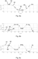
- Algorithm 1 is in the Figures 2a-c for the slewing gear ( Figure 2a ), the boom ( Figure 2b ) and the stem ( Figure 2c ) shown.
- Algorithm 2 which is downstream of algorithm 1, is intended to sort out characteristic points 20 that have a small spatial distance from one another. It is important that the first and last characteristic point 20 of a stop-start movement is retained. In algorithm 2, for each characteristic point 20, the spatial distance to the previous (“p k-1 ”) and to the following (“p k+1 ”) characteristic point 20 is considered. If both distances are smaller than a second threshold value p TH , this characteristic point p k under consideration is sorted out. Algorithm 2 is demonstrated using the following pseudocode example.
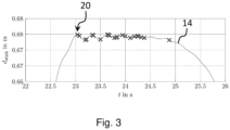
- FIGS 4a-c show for the three actuators ( Figure 4a : slewing gear, Figure 4b : boom, Figure 4c : stem) which is in the Figures 2a-c trajectories 10, 12, 14 shown with the characteristic points 20 found by algorithm 1, which are identified as before by the symbol “x”.
- the unique characteristic points 30 filtered out by algorithm 2 are represented by a circle symbol.
- Figure 5 is again the one indicated by the dotted box in Figure 4c marked area shown enlarged.
- the characteristic points 20 and the unique characteristic points 30 are shown superimposed.
- the algorithm 2 sorts out the characteristic points 20, which were caused by vibrations of the actuators, and no longer considers them. Only the start and stop points of the movements are identified as unique characteristic points 30. The use of algorithm 2 thus reduces the total number of characteristic points 20 and thus the number of points to be approached automatically in the departure mode. However, the filtering out occurs without any essential information for the movement to be automatically executed being lost in the departure mode.
- the points 30 must be synchronized in time for all actuators. So if a clear characteristic point 30 is determined for an actuator, the positions of the other actuators are also saved as points at this point in time, although these other movement trajectories 10, 12, 14 do not have to be characteristic points 20. These additionally stored points are called synchronization points 40. Overall, all of them are part of a movement path 10, 12, 14 of an actuator stored points 30, 40 are synchronized in time with the stored points 30, 40 of the other actuators.
- time-synchronized points 30, 40 are approached for all actuators and the entire movement sequence is based on the movement trajectories 10, 12, 14 recorded in the learning mode.
- other trajectories result (both in actuator coordinates and in joint or TCP coordinates), since the trajectories 10, 12, 14 of the individual components are re-planned or calculated by the planning means.
- points 30, 40 stored for the different movement trajectories 10, 12, 14 are automatically moved by appropriate control of the actuators using the controller.
- the set of points to be approached therefore includes the unique characteristic points 30 found by algorithms 1 and 2 as well as the additionally stored synchronization points 40. This means that each point vector of this point set or point matrix is approached one after the other.
- the re-planning of the trajectories 10, 12, 14 to be traveled from one point 30, 40 to the next point 30, 40 is carried out by a planning means in the form of a trajectory generation algorithm or trajectory planner.
- a planning means in the form of a trajectory generation algorithm or trajectory planner.
- This can be, for example, a C n -trajectory planner for the position.
- C n means “n-fold continuously differentiable with respect to position”. How often the position trajectory or the newly calculated movement path must be differentiable depends on the feedforward control used for the actuator speed.
- the trajectory planner is parameterized by specifying the restrictions on the n derivatives as well as the restriction on the input of the n+1th integrator, which optimally shows bang-bang behavior. All known trajectory planners can be used to re-plan the movement trajectories 10, 12, 14. For example, a C 2 trajectory can be planned based on the feedforward control used.
- the parameterization is carried out by specifying the positive and negative restrictions on speed, acceleration and
- this search does not synchronize to the exact same end time, but rather a freely selectable parameter is defined as a threshold value or time window. If the end time of the movement path 10, 12, 14 to be synchronized is within this time window around the end time of the slowest actuator, the synchronization has ended successfully.
- the time window can preferably be set or changed by the operator. It should be noted that the synchronization algorithm works for any number of actuators. In addition, different trajectory planners can be used using the corresponding parameters.
- the movement paths 10, 12, 14 are planned for all actuators to the next point 30, 40, these are made available as reference values to the lower-level controllers.
- the generated trajectories 10, 12, 14 are evaluated at each discrete time step.
- the step size of the discretization can be parameterized as desired. If all position trajectories or movement paths 10, 12, 14 are within a parameterizable radius or distance threshold value around the target points 30, 40 to be approached, the calculation of the next movement path sections of the actuators, including the temporal end point synchronization, takes place to the next points 30 to be approached , 40.
- the current reference values of each movement path 10, 12, 14 are used as starting values for the trajectories 10, 12, 14, so that the process is as fluid as possible.
- the distance threshold values can be parameterized separately for each point 30, 40 and for each actuator.
- At least one parameter of the automatic movement carried out in the departure mode can be varied.
- the operator of the working device 1 can specify the speed of all actuators via an input.
- an independent input means can be provided, or he can use the input means available for the manual control of the implement 1 (e.g. master switch).
- the parameters or boundary conditions of the trajectory planning are automatically adjusted in order to achieve optimal guidance behavior.
- the re-planning of the movement trajectories 10, 12, 14 using the planning means can be adapted under various criteria. Restrictions resulting from the environment and/or the characteristics of the implement are taken into account. Examples of variable parameters are the minimum energy input, a short processing time, a shortest route or a small deviation from the learned trajectories 10, 12, 14. Also restrictions that resulting from the existing infrastructure can ideally be taken into account. In addition, it is advantageously possible to suitably move the pick-up and/or unloading position if necessary. For this purpose, it can also be provided that an offset parameter can be defined, by which the start and/or end position of the movement is automatically shifted with each work step.
- the teaching of the movement paths 10, 12, 14 in the learning mode can be done as an alternative or in addition to a manual execution of the movement or manual operation by an algorithm that detects the driver's operating patterns.
- the control recognizes repeating work cycles and generates corresponding trajectories 10, 12, 14, which can be traversed in travel mode.
- An essential characteristic of the departure mode is that the movement trajectories 10, 12, 14 from the current point vector 30, 40 to the next point vector 30, 40 are re-planned or calculated by the planning means under temporal synchronization aspects.
- the speed of an actuator between two unique characteristic points 30 i.e. between two start and stop points of a movement
- a remedy for this can be a non-fixed synchronization of the movement path 10 of the slewing gear as well as a synchronization of only the movement paths 12, 14 of the moving components (boom and arm).
- the same detection of the unique characteristic points 30 takes place using algorithms 1 and 2 as described above.
- the start and end rotation angles 30 of the slewing gear are recorded.
- the boom and the arm are moved synchronously with one another to the respective point vector 30, 40.
- the movement path 10 of the slewing gear from the initial angle of rotation 30 to the end angle of rotation 30 is planned directly.
- the remaining actuators are then controlled according to the angle of rotation. This guarantees smooth movement of the slewing gear.
- a task requires the repeated approach to two positions, for example a first position for picking up material or a load and a second position for unloading material
- the movement taught in in learning mode only in one direction, for example from the pick-up - to the unloading position.
- the order of movement in departure mode can then be reversed by the operator or the control. This makes it possible for the pickup position or the unloading position to be approached depending on the current position of all actuators upon operator input.
- the slewing gear is not in the pick-up or unloading position at the start of a movement of the implement 1. It may therefore make sense not to first move the slewing gear to the start position, which depends on the desired movement (picking up or unloading), and only then to the desired end position, but rather from the current position of the slewing gear first other actuators (i.e. boom and stick). These movements 12, 14 take place until a change in the angle of rotation occurs or becomes necessary in the target points 30, 40 to be traveled. Only then is the movement path 10 of the slewing gear planned from the current position to the desired end position.
- An additional optional extension affects all actuators except the slewing gear.
- Material is usually picked up by the implement 1 from a low height.
- the tool center point (TCP) is then moved vertically upwards. If in learning mode the position of the TCP in the vertical direction is higher than the TCP position of the first point 30, 40 to be traveled in the vertical direction, it does not make sense to first move vertically downwards and then upwards again before the rotary movement starts . Therefore, all target point vectors 30, 40 that have a lower vertical TCP position than the current TCP position can be skipped. Skipping is carried out at most until the movement of the slewing gear starts.
Landscapes
- Engineering & Computer Science (AREA)
- Automation & Control Theory (AREA)
- Civil Engineering (AREA)
- Structural Engineering (AREA)
- General Engineering & Computer Science (AREA)
- Mining & Mineral Resources (AREA)
- Physics & Mathematics (AREA)
- General Physics & Mathematics (AREA)
- Mechanical Engineering (AREA)
- Manipulator (AREA)
- Operation Control Of Excavators (AREA)
- Numerical Control (AREA)
- Lifting Devices For Agricultural Implements (AREA)
Claims (12)
- Procédé pour le déplacement automatique d'un appareil de travail (1), notamment d'un appareil de manutention de matériaux ou de terrassement, l'appareil de travail (1) comprenant une commande et au moins deux composants qui peuvent chacun être déplacés indépendamment l'un de l'autre au moyen d'un actionneur pouvant être commandé par la commande, la commande présentant un mode d'apprentissage et un mode de parcours et, en mode de parcours, l'appareil de travail (1) étant déplacé automatiquement d'une première position dans une deuxième position par une commande correspondante des actionneurs,la commande en mode d'apprentissage détectant et enregistrant pendant un déplacement de l'appareil de travail (1) des données concernant les déplacements individuels des composants, la commande des actionneurs pendant le déplacement automatique de l'appareil de travail (1) en mode de parcours s'effectuant sur la base de ces données et au moins un paramètre du déplacement automatique de l'appareil de travail (1) pouvant être réglé par l'opérateur,la commande en mode d'apprentissage détectant les trajectoires de déplacement (10, 12, 14) des actionneurs à des intervalles de temps discrets, les données détectées comprenant les positions momentanées,caractérisé en ce quela commande en mode d'apprentissage détecte en outre, lors de la détection des trajectoires de déplacement (10, 12, 14) des actionneurs à des intervalles de temps discrets, les vitesses momentanées des actionneurs, et enregistre pour chaque trajectoire de déplacement (10, 12, 14) les positions d'actionneur momentanées en tant que points caractéristiques (20), les points caractéristiques (20) comprenant les positions d'actionneur au début et/ou à la fin d'un déplacement d'actionneur, la commande classant une position d'actionneur momentanée à un instant déterminé comme point caractéristique (20) si au moins une condition concernant la vitesse d'actionneur momentanée est remplie,la condition étant remplie lorsque la vitesse d'actionneur momentanée est supérieure à une première valeur seuil au début d'un déplacement d'actionneur ou inférieure à la fin d'un déplacement d'actionneur et/ou lorsque le signe de la vitesse d'actionneur momentanée change.
- Procédé selon la revendication 1, caractérisé en ce que le paramètre réglable est une vitesse maximale ou minimale d'un ou plusieurs actionneurs, un apport minimal d'énergie, un trajet le plus court, le plus rapide ou optimisé à l'aide d'autres critères ou une position, notamment la position initiale ou finale, de l'appareil de travail (1).
- Procédé selon la revendication 1 ou 2, caractérisé en ce que la commande n'enregistre que les points caractéristiques (30) dont la distance à un point caractéristique (20) directement précédent et/ou suivant est supérieure à une deuxième valeur seuil.
- Procédé selon l'une quelconque des revendications 1 à 3, caractérisé en ce que la commande en mode d'apprentissage pour chaque trajectoire de déplacement (10, 12, 14) enregistre en outre les positions d'actionneur (40) non classées comme point caractéristique (20) aux instants qui correspondent aux instants des points caractéristiques détectés (20, 30) des autres trajectoires de déplacement (10, 12, 14), de telle sorte que les instants de l'ensemble des positions d'actionneur enregistrées (20, 30, 40) d'une trajectoire de déplacement (10, 12, 14) correspondent aux instants de l'ensemble des positions d'actionneur caractéristiques enregistrées (20, 30, 40) des autres trajectoires de déplacement (10, 12, 14).
- Procédé selon la revendication 4, caractérisé en ce que la commande commande les actionneurs de telle sorte que tous les actionneurs atteignent simultanément les positions d'actionneur (20, 30, 40) qui se correspondent dans le temps à l'intérieur d'une fenêtre de temps de préférence réglable, les vitesses de tous les actionneurs étant adaptées à l'actionneur le plus lent, l'adaptation s'effectuant notamment au moyen d'un procédé itératif.
- Procédé selon l'une quelconque des revendications 4 à 5, caractérisé en ce que la commande en mode de parcours commande les différents actionneurs sur la base des positions d'actionneur enregistrées (20, 30, 40) pour chaque trajectoire de déplacement (10, 12, 14), la commande comprenant un moyen de planification qui calcule les trajectoires de déplacement (10, 12, 14) à parcourir automatiquement sur la base des positions d'actionneur enregistrées (20, 30, 40), les actionneurs étant commandés de telle sorte qu'ils suivent les trajectoires de déplacement (10, 12, 14) calculées.
- Procédé selon la revendication 6, caractérisé en ce que le moyen de planification recalcule les trajectoires de déplacement (10, 12, 14) à parcourir des actionneurs respectivement par sections entre deux positions d'actionneur enregistrées (20, 30, 40) voisines, le moyen de planification calculant la section de trajectoire de déplacement suivante jusqu'à la position d'actionneur enregistrée (20, 30, 40) suivante dès que la position momentanée d'un actionneur est inférieure à une valeur seuil de distance de préférence réglable par rapport à la position d'actionneur enregistrée (20, 30, 40) actuellement atteinte.
- Procédé selon la revendication 6 ou 7, caractérisé en ce que le calcul des trajectoires de déplacement (10, 12, 14) par le moyen de planification s'effectue sous des conditions limites définies, au moins une condition limite pouvant être réglée par l'opérateur, notamment par le biais d'une unité de saisie reliée à la commande, et l'au moins une condition limite réglable consistant de préférence en une vitesse maximale ou minimale d'un ou plusieurs actionneurs, un apport minimal d'énergie, un trajet le plus court, le plus rapide ou optimisé sur la base d'autres critères et/ou une position, notamment la position initiale ou finale, de l'appareil de travail (1).
- Procédé selon la revendication 1, caractérisé en ce que, sur la base des positions et des vitesses d'actionneur détectées, une trajectoire optimale en termes de temps est calculée, laquelle est parcourue automatiquement en mode de parcours, les chemins de position détectés en mode d'apprentissage pour chaque actionneur n'étant pas adaptées, la vitesse de chaque actionneur étant mise à l'échelle à chaque pas de balayage, un seul facteur de mise à l'échelle étant utilisé pour la mise à l'échelle à chaque pas de balayage, et le calcul de la trajectoire optimale en termes de temps tenant de préférence compte de contraintes physiques des actionneurs et/ou des composants, telles que les vitesses maximales des actionneurs, les accélérations maximales des actionneurs, une secousse maximale d'un ou plusieurs actionneurs et/ou un débit maximal d'une pompe.
- Procédé selon l'une quelconque des revendications précédentes, caractérisé en ce que le déplacement de l'appareil de travail (1) détecté en mode d'apprentissage est effectué sur la base d'une commande manuelle.
- Procédé selon l'une quelconque des revendications précédentes, caractérisé en ce qu'un premier composant est un chariot supérieur (3) monté à rotation sur un chariot inférieur (2) de l'appareil de travail (1) et un deuxième composant est un premier élément de flèche monté sur le chariot supérieur (3) de manière à pouvoir pivoter autour d'un axe horizontal, un troisième composant étant de préférence un deuxième élément de flèche monté de manière à pouvoir pivoter sur la flèche.
- Appareil de travail (1), notamment appareil de manutention de matériaux ou de terrassement, avec une commande pour la mise en oeuvre du procédé selon l'une quelconque des revendications précédentes.
Applications Claiming Priority (1)
| Application Number | Priority Date | Filing Date | Title |
|---|---|---|---|
| DE102019120633.2A DE102019120633B4 (de) | 2019-07-31 | 2019-07-31 | Verfahren zur automatischen Bewegung eines Arbeitsgeräts sowie Arbeitsgerät |
Publications (2)
| Publication Number | Publication Date |
|---|---|
| EP3771952A1 EP3771952A1 (fr) | 2021-02-03 |
| EP3771952B1 true EP3771952B1 (fr) | 2023-11-15 |
Family
ID=71108393
Family Applications (1)
| Application Number | Title | Priority Date | Filing Date |
|---|---|---|---|
| EP20180656.9A Active EP3771952B1 (fr) | 2019-07-31 | 2020-06-18 | Procédé de déplacement automatique d'un appareil de travail ainsi qu'appareil de travail |
Country Status (6)
| Country | Link |
|---|---|
| US (1) | US20210032848A1 (fr) |
| EP (1) | EP3771952B1 (fr) |
| CN (1) | CN112299254A (fr) |
| DE (1) | DE102019120633B4 (fr) |
| FI (1) | FI3771952T3 (fr) |
| RU (1) | RU2020125257A (fr) |
Families Citing this family (6)
| Publication number | Priority date | Publication date | Assignee | Title |
|---|---|---|---|---|
| DE102021103126B4 (de) | 2021-02-10 | 2023-10-12 | Gerhard Schubert Gesellschaft mit beschränkter Haftung | Verfahren zum Beschleunigen einer Handhabungs-Maschine |
| CN113459103B (zh) * | 2021-07-09 | 2022-07-12 | 深圳市朗宇芯科技有限公司 | 一种机械手自动运行时的转角轨迹控制方法及装置 |
| CN113684885B (zh) * | 2021-08-19 | 2022-09-02 | 上海三一重机股份有限公司 | 作业机械控制方法、装置及作业机械 |
| JP2023074041A (ja) * | 2021-11-17 | 2023-05-29 | コベルコ建機株式会社 | 作業機械 |
| EP4186847B1 (fr) | 2021-11-30 | 2024-05-08 | B&R Industrial Automation GmbH | Planification de trajectoire avec fonctionnalité de replanification flexible - point d'extrémité modifié |
| JP2023163273A (ja) * | 2022-04-28 | 2023-11-10 | 大成建設株式会社 | 施工支援装置及び施工支援方法 |
Family Cites Families (23)
| Publication number | Priority date | Publication date | Assignee | Title |
|---|---|---|---|---|
| GB2252642B (en) * | 1990-12-31 | 1995-05-24 | Samsung Heavy Ind | System for automatically controlling operation of construction vehicle |
| FR2764401B1 (fr) * | 1997-06-04 | 1999-09-10 | Renault Agriculture | Procede d'automatisation des taches repetitives sur un engin et dispositif correspondant |
| JPH11315556A (ja) | 1997-12-19 | 1999-11-16 | Carnegie Mellon Univ | 土工機械の自律制御を最適化する学習システムおよび方法 |
| GB0128803D0 (en) * | 2001-12-03 | 2002-01-23 | New Holland Uk Ltd | Agricultural vehicle |
| DE102004056861A1 (de) | 2004-11-25 | 2006-06-08 | Kuka Roboter Gmbh | Verfahren und Vorrichtung zum Regeln, Steuern von Manipulatoren |
| US9108316B2 (en) | 2008-12-10 | 2015-08-18 | Abb Research Ltd. | Method and system for in-production optimization of the parameters of a robot used for assembly |
| DE102009049172B4 (de) | 2009-10-13 | 2019-07-25 | Kuka Roboter Gmbh | Verfahren und Vorrichtung zur Steuerung eines Manipulators |
| DE102011011542B4 (de) | 2011-02-17 | 2016-05-25 | Convergent Information Technologies Gmbh | Verfahren zur automatisierten Programmierung und Optimierung von robotischen Arbeitsabläufen |
| ITTO20110834A1 (it) * | 2011-09-20 | 2013-03-21 | Soilmec Spa | Sistema di controllo per una macchina di scavo e/o perforazione di terreni e macchina di scavo e/o perforazione comprendente tale sistema. |
| JP6347595B2 (ja) * | 2013-11-25 | 2018-06-27 | キヤノン株式会社 | ロボット制御方法、及びロボット制御装置 |
| JP6247174B2 (ja) * | 2014-08-01 | 2017-12-13 | 株式会社クボタ | 運転支援システム |
| WO2017088888A1 (fr) * | 2015-11-24 | 2017-06-01 | Science Ventures Denmark A/S | Apprentissage de trajectoire ou chemin de robot par démonstration |
| JP7265473B2 (ja) * | 2016-09-26 | 2023-04-26 | ファナック アメリカ コーポレイション | プレス機とロボットとを同期させる方法 |
| US10571902B2 (en) * | 2016-10-12 | 2020-02-25 | Sisu Devices Llc | Robotic programming and motion control |
| DE102016220577A1 (de) | 2016-10-20 | 2018-05-09 | Robert Bosch Gmbh | Verfahren zum Optimieren von Bewegungskonturen eines Manipulators |
| JP6438450B2 (ja) * | 2016-11-29 | 2018-12-12 | ファナック株式会社 | レーザ加工ロボットの加工順序を学習する機械学習装置、ロボットシステムおよび機械学習方法 |
| JP6457473B2 (ja) * | 2016-12-16 | 2019-01-23 | ファナック株式会社 | ロボットおよびレーザスキャナの動作を学習する機械学習装置,ロボットシステムおよび機械学習方法 |
| WO2018124610A1 (fr) | 2016-12-28 | 2018-07-05 | 한국기계연구원 | Appareil d'enseignement de robot |
| JP6577522B2 (ja) * | 2017-06-07 | 2019-09-18 | ファナック株式会社 | 制御装置及び機械学習装置 |
| JP6506348B2 (ja) | 2017-06-14 | 2019-04-24 | ファナック株式会社 | ロボットの軌道を修正するロボットの教示装置 |
| JP6838017B2 (ja) * | 2018-08-31 | 2021-03-03 | ファナック株式会社 | レーザ加工のための教示装置、教示方法、及び教示プログラム |
| JP6773098B2 (ja) * | 2018-10-17 | 2020-10-21 | 株式会社安川電機 | ロボットシステム及びロボット制御方法 |
| JP7339776B2 (ja) * | 2019-05-28 | 2023-09-06 | 川崎重工業株式会社 | 制御システム、機械装置システム及び制御方法 |
-
2019
- 2019-07-31 DE DE102019120633.2A patent/DE102019120633B4/de not_active Expired - Fee Related
-
2020
- 2020-06-18 EP EP20180656.9A patent/EP3771952B1/fr active Active
- 2020-06-18 FI FIEP20180656.9T patent/FI3771952T3/fi active
- 2020-07-29 US US16/942,689 patent/US20210032848A1/en not_active Abandoned
- 2020-07-29 CN CN202010745893.8A patent/CN112299254A/zh active Pending
- 2020-07-30 RU RU2020125257A patent/RU2020125257A/ru unknown
Also Published As
| Publication number | Publication date |
|---|---|
| FI3771952T3 (fi) | 2023-12-18 |
| CN112299254A (zh) | 2021-02-02 |
| DE102019120633A1 (de) | 2021-02-04 |
| US20210032848A1 (en) | 2021-02-04 |
| RU2020125257A (ru) | 2022-01-31 |
| EP3771952A1 (fr) | 2021-02-03 |
| DE102019120633B4 (de) | 2022-05-05 |
Similar Documents
| Publication | Publication Date | Title |
|---|---|---|
| EP3771952B1 (fr) | Procédé de déplacement automatique d'un appareil de travail ainsi qu'appareil de travail | |
| EP3523168B1 (fr) | Procédé et dispositif de régulation de la dynamique de conduite pour un véhicule automobile | |
| DE112018005832B4 (de) | Bewegungseinstellungsvorrichtung für roboter, bewegungssteuerungssystem und robotersystem | |
| DE69417323T2 (de) | Verfahren zur Optimierung der Bewegung eines Mehr-Achsen-Roboters | |
| DE102014224193B9 (de) | Verfahren und Vorrichtung zur Fehlerhandhabung eines Roboters | |
| EP3115856A1 (fr) | Procédé de détermination de trajectoire pour mouvements de temps mort | |
| DE102019205971A1 (de) | Steuersystem für ein arbeitsfahrzeug mit koordinierter steuerung der stellglieder | |
| AT525225A1 (de) | Verfahren und Vorrichtung zur Bestimmung einer zeitoptimalen Trajektorie | |
| EP2208584B1 (fr) | Procédé destiné à la commande de robots industriels | |
| EP4731393A1 (fr) | Procédé et système d'actionnement d'un robot | |
| EP1675709A2 (fr) | Procede pour imprimer un mouvement a un appareil de manutention et dispositif de traitement d'image | |
| DE102017116788B4 (de) | Roboter-Steuerungsvorrichtung und Verfahren zur Steuerung derselben | |
| DE112019007889T5 (de) | Bearbeitungsprogramm-umwandlungseinrichtung, numerische-steuereinrichtung und bearbeitungsprogramm-umwandlungsverfahren | |
| DE102021117448A1 (de) | Steuerverfahren für ein teleoperiertes kraftfahrzeug | |
| EP4435184A1 (fr) | Dispositif pour machine de travail à articulation offset, procédé et dispositif de commande d'une excavatrice offset | |
| DE102022104586B3 (de) | Vorrichtung für das Steuern einer Rückführung eines Roboters zu seinem Ursprung und Verfahren zum Suchen eines Rückführungspfads des Roboters zu seinem Ursprung | |
| DE102020103852B4 (de) | Erzeugen und Optimieren eines Steuerprogramms für einen Robotermanipulator | |
| EP3969673B1 (fr) | Procédé de calcul d'un volume d'excavation | |
| DE102017103144A1 (de) | Verfahren und Vorrichtung zur Klassifizierung von Begrenzungsabschnitten einer landwirtschaftlichen Fläche | |
| DE19809382C2 (de) | Steuerungssystem für Handlingmaschinen | |
| EP4429926B1 (fr) | Procédé et dispositif de commande longitudinale d'un véhicule | |
| DE102024205985B3 (de) | Verfahren zur Anpassung einer Geschwindigkeit eines Endeffektors eines Roboters und Roboter | |
| EP3887911A1 (fr) | Procédé de commande d'un processus d'automatisation en temps réel | |
| DE102019207161A1 (de) | Verfahren zur Ermittlung des Platzbedarfs einer Baumaschine, eines Arbeitsarms und eines Werkzeugs | |
| DE102019207151A1 (de) | Verfahren zur Analyse der Bodenbeschaffenheit und/oder des Härtegrads des Bodens |
Legal Events
| Date | Code | Title | Description |
|---|---|---|---|
| PUAI | Public reference made under article 153(3) epc to a published international application that has entered the european phase |
Free format text: ORIGINAL CODE: 0009012 |
|
| STAA | Information on the status of an ep patent application or granted ep patent |
Free format text: STATUS: THE APPLICATION HAS BEEN PUBLISHED |
|
| AK | Designated contracting states |
Kind code of ref document: A1 Designated state(s): AL AT BE BG CH CY CZ DE DK EE ES FI FR GB GR HR HU IE IS IT LI LT LU LV MC MK MT NL NO PL PT RO RS SE SI SK SM TR |
|
| AX | Request for extension of the european patent |
Extension state: BA ME |
|
| STAA | Information on the status of an ep patent application or granted ep patent |
Free format text: STATUS: REQUEST FOR EXAMINATION WAS MADE |
|
| 17P | Request for examination filed |
Effective date: 20210712 |
|
| STAA | Information on the status of an ep patent application or granted ep patent |
Free format text: STATUS: EXAMINATION IS IN PROGRESS |
|
| 17Q | First examination report despatched |
Effective date: 20220413 |
|
| GRAP | Despatch of communication of intention to grant a patent |
Free format text: ORIGINAL CODE: EPIDOSNIGR1 |
|
| STAA | Information on the status of an ep patent application or granted ep patent |
Free format text: STATUS: GRANT OF PATENT IS INTENDED |
|
| INTG | Intention to grant announced |
Effective date: 20230601 |
|
| GRAS | Grant fee paid |
Free format text: ORIGINAL CODE: EPIDOSNIGR3 |
|
| RAP3 | Party data changed (applicant data changed or rights of an application transferred) |
Owner name: LIEBHERR-HYDRAULIKBAGGER GMBH |
|
| GRAA | (expected) grant |
Free format text: ORIGINAL CODE: 0009210 |
|
| STAA | Information on the status of an ep patent application or granted ep patent |
Free format text: STATUS: THE PATENT HAS BEEN GRANTED |
|
| AK | Designated contracting states |
Kind code of ref document: B1 Designated state(s): AL AT BE BG CH CY CZ DE DK EE ES FI FR GB GR HR HU IE IS IT LI LT LU LV MC MK MT NL NO PL PT RO RS SE SI SK SM TR |
|
| REG | Reference to a national code |
Ref country code: CH Ref legal event code: EP Ref country code: GB Ref legal event code: FG4D Free format text: NOT ENGLISH |
|
| REG | Reference to a national code |
Ref country code: DE Ref legal event code: R096 Ref document number: 502020006005 Country of ref document: DE |
|
| REG | Reference to a national code |
Ref country code: IE Ref legal event code: FG4D Free format text: LANGUAGE OF EP DOCUMENT: GERMAN |
|
| REG | Reference to a national code |
Ref country code: FI Ref legal event code: FGE |
|
| REG | Reference to a national code |
Ref country code: NL Ref legal event code: FP |
|
| REG | Reference to a national code |
Ref country code: SE Ref legal event code: TRGR |
|
| REG | Reference to a national code |
Ref country code: LT Ref legal event code: MG9D |
|
| PG25 | Lapsed in a contracting state [announced via postgrant information from national office to epo] |
Ref country code: GR Free format text: LAPSE BECAUSE OF FAILURE TO SUBMIT A TRANSLATION OF THE DESCRIPTION OR TO PAY THE FEE WITHIN THE PRESCRIBED TIME-LIMIT Effective date: 20240216 |
|
| PG25 | Lapsed in a contracting state [announced via postgrant information from national office to epo] |
Ref country code: IS Free format text: LAPSE BECAUSE OF FAILURE TO SUBMIT A TRANSLATION OF THE DESCRIPTION OR TO PAY THE FEE WITHIN THE PRESCRIBED TIME-LIMIT Effective date: 20240315 |
|
| PG25 | Lapsed in a contracting state [announced via postgrant information from national office to epo] |
Ref country code: LT Free format text: LAPSE BECAUSE OF FAILURE TO SUBMIT A TRANSLATION OF THE DESCRIPTION OR TO PAY THE FEE WITHIN THE PRESCRIBED TIME-LIMIT Effective date: 20231115 |
|
| PG25 | Lapsed in a contracting state [announced via postgrant information from national office to epo] |
Ref country code: ES Free format text: LAPSE BECAUSE OF FAILURE TO SUBMIT A TRANSLATION OF THE DESCRIPTION OR TO PAY THE FEE WITHIN THE PRESCRIBED TIME-LIMIT Effective date: 20231115 |
|
| PG25 | Lapsed in a contracting state [announced via postgrant information from national office to epo] |
Ref country code: LT Free format text: LAPSE BECAUSE OF FAILURE TO SUBMIT A TRANSLATION OF THE DESCRIPTION OR TO PAY THE FEE WITHIN THE PRESCRIBED TIME-LIMIT Effective date: 20231115 Ref country code: IS Free format text: LAPSE BECAUSE OF FAILURE TO SUBMIT A TRANSLATION OF THE DESCRIPTION OR TO PAY THE FEE WITHIN THE PRESCRIBED TIME-LIMIT Effective date: 20240315 Ref country code: GR Free format text: LAPSE BECAUSE OF FAILURE TO SUBMIT A TRANSLATION OF THE DESCRIPTION OR TO PAY THE FEE WITHIN THE PRESCRIBED TIME-LIMIT Effective date: 20240216 Ref country code: ES Free format text: LAPSE BECAUSE OF FAILURE TO SUBMIT A TRANSLATION OF THE DESCRIPTION OR TO PAY THE FEE WITHIN THE PRESCRIBED TIME-LIMIT Effective date: 20231115 Ref country code: BG Free format text: LAPSE BECAUSE OF FAILURE TO SUBMIT A TRANSLATION OF THE DESCRIPTION OR TO PAY THE FEE WITHIN THE PRESCRIBED TIME-LIMIT Effective date: 20240215 Ref country code: PT Free format text: LAPSE BECAUSE OF FAILURE TO SUBMIT A TRANSLATION OF THE DESCRIPTION OR TO PAY THE FEE WITHIN THE PRESCRIBED TIME-LIMIT Effective date: 20240315 |
|
| PG25 | Lapsed in a contracting state [announced via postgrant information from national office to epo] |
Ref country code: RS Free format text: LAPSE BECAUSE OF FAILURE TO SUBMIT A TRANSLATION OF THE DESCRIPTION OR TO PAY THE FEE WITHIN THE PRESCRIBED TIME-LIMIT Effective date: 20231115 Ref country code: PL Free format text: LAPSE BECAUSE OF FAILURE TO SUBMIT A TRANSLATION OF THE DESCRIPTION OR TO PAY THE FEE WITHIN THE PRESCRIBED TIME-LIMIT Effective date: 20231115 Ref country code: NO Free format text: LAPSE BECAUSE OF FAILURE TO SUBMIT A TRANSLATION OF THE DESCRIPTION OR TO PAY THE FEE WITHIN THE PRESCRIBED TIME-LIMIT Effective date: 20240215 Ref country code: LV Free format text: LAPSE BECAUSE OF FAILURE TO SUBMIT A TRANSLATION OF THE DESCRIPTION OR TO PAY THE FEE WITHIN THE PRESCRIBED TIME-LIMIT Effective date: 20231115 Ref country code: HR Free format text: LAPSE BECAUSE OF FAILURE TO SUBMIT A TRANSLATION OF THE DESCRIPTION OR TO PAY THE FEE WITHIN THE PRESCRIBED TIME-LIMIT Effective date: 20231115 |
|
| PG25 | Lapsed in a contracting state [announced via postgrant information from national office to epo] |
Ref country code: DK Free format text: LAPSE BECAUSE OF FAILURE TO SUBMIT A TRANSLATION OF THE DESCRIPTION OR TO PAY THE FEE WITHIN THE PRESCRIBED TIME-LIMIT Effective date: 20231115 |
|
| PG25 | Lapsed in a contracting state [announced via postgrant information from national office to epo] |
Ref country code: CZ Free format text: LAPSE BECAUSE OF FAILURE TO SUBMIT A TRANSLATION OF THE DESCRIPTION OR TO PAY THE FEE WITHIN THE PRESCRIBED TIME-LIMIT Effective date: 20231115 |
|
| PG25 | Lapsed in a contracting state [announced via postgrant information from national office to epo] |
Ref country code: SK Free format text: LAPSE BECAUSE OF FAILURE TO SUBMIT A TRANSLATION OF THE DESCRIPTION OR TO PAY THE FEE WITHIN THE PRESCRIBED TIME-LIMIT Effective date: 20231115 |
|
| PG25 | Lapsed in a contracting state [announced via postgrant information from national office to epo] |
Ref country code: SM Free format text: LAPSE BECAUSE OF FAILURE TO SUBMIT A TRANSLATION OF THE DESCRIPTION OR TO PAY THE FEE WITHIN THE PRESCRIBED TIME-LIMIT Effective date: 20231115 Ref country code: SK Free format text: LAPSE BECAUSE OF FAILURE TO SUBMIT A TRANSLATION OF THE DESCRIPTION OR TO PAY THE FEE WITHIN THE PRESCRIBED TIME-LIMIT Effective date: 20231115 Ref country code: RO Free format text: LAPSE BECAUSE OF FAILURE TO SUBMIT A TRANSLATION OF THE DESCRIPTION OR TO PAY THE FEE WITHIN THE PRESCRIBED TIME-LIMIT Effective date: 20231115 Ref country code: EE Free format text: LAPSE BECAUSE OF FAILURE TO SUBMIT A TRANSLATION OF THE DESCRIPTION OR TO PAY THE FEE WITHIN THE PRESCRIBED TIME-LIMIT Effective date: 20231115 Ref country code: DK Free format text: LAPSE BECAUSE OF FAILURE TO SUBMIT A TRANSLATION OF THE DESCRIPTION OR TO PAY THE FEE WITHIN THE PRESCRIBED TIME-LIMIT Effective date: 20231115 Ref country code: CZ Free format text: LAPSE BECAUSE OF FAILURE TO SUBMIT A TRANSLATION OF THE DESCRIPTION OR TO PAY THE FEE WITHIN THE PRESCRIBED TIME-LIMIT Effective date: 20231115 |
|
| REG | Reference to a national code |
Ref country code: DE Ref legal event code: R097 Ref document number: 502020006005 Country of ref document: DE |
|
| PLBE | No opposition filed within time limit |
Free format text: ORIGINAL CODE: 0009261 |
|
| STAA | Information on the status of an ep patent application or granted ep patent |
Free format text: STATUS: NO OPPOSITION FILED WITHIN TIME LIMIT |
|
| 26N | No opposition filed |
Effective date: 20240819 |
|
| PG25 | Lapsed in a contracting state [announced via postgrant information from national office to epo] |
Ref country code: SI Free format text: LAPSE BECAUSE OF FAILURE TO SUBMIT A TRANSLATION OF THE DESCRIPTION OR TO PAY THE FEE WITHIN THE PRESCRIBED TIME-LIMIT Effective date: 20231115 |
|
| PG25 | Lapsed in a contracting state [announced via postgrant information from national office to epo] |
Ref country code: SI Free format text: LAPSE BECAUSE OF FAILURE TO SUBMIT A TRANSLATION OF THE DESCRIPTION OR TO PAY THE FEE WITHIN THE PRESCRIBED TIME-LIMIT Effective date: 20231115 |
|
| PG25 | Lapsed in a contracting state [announced via postgrant information from national office to epo] |
Ref country code: MC Free format text: LAPSE BECAUSE OF FAILURE TO SUBMIT A TRANSLATION OF THE DESCRIPTION OR TO PAY THE FEE WITHIN THE PRESCRIBED TIME-LIMIT Effective date: 20231115 |
|
| REG | Reference to a national code |
Ref country code: CH Ref legal event code: PL |
|
| PG25 | Lapsed in a contracting state [announced via postgrant information from national office to epo] |
Ref country code: LU Free format text: LAPSE BECAUSE OF NON-PAYMENT OF DUE FEES Effective date: 20240618 |
|
| PG25 | Lapsed in a contracting state [announced via postgrant information from national office to epo] |
Ref country code: IE Free format text: LAPSE BECAUSE OF NON-PAYMENT OF DUE FEES Effective date: 20240618 |
|
| PG25 | Lapsed in a contracting state [announced via postgrant information from national office to epo] |
Ref country code: CH Free format text: LAPSE BECAUSE OF NON-PAYMENT OF DUE FEES Effective date: 20240630 |
|
| PGFP | Annual fee paid to national office [announced via postgrant information from national office to epo] |
Ref country code: FI Payment date: 20250624 Year of fee payment: 6 |
|
| PGFP | Annual fee paid to national office [announced via postgrant information from national office to epo] |
Ref country code: GB Payment date: 20250621 Year of fee payment: 6 |
|
| PGFP | Annual fee paid to national office [announced via postgrant information from national office to epo] |
Ref country code: NL Payment date: 20250621 Year of fee payment: 6 Ref country code: BE Payment date: 20250621 Year of fee payment: 6 |
|
| PGFP | Annual fee paid to national office [announced via postgrant information from national office to epo] |
Ref country code: FR Payment date: 20250617 Year of fee payment: 6 |
|
| PGFP | Annual fee paid to national office [announced via postgrant information from national office to epo] |
Ref country code: AT Payment date: 20250721 Year of fee payment: 5 |
|
| PGFP | Annual fee paid to national office [announced via postgrant information from national office to epo] |
Ref country code: SE Payment date: 20250621 Year of fee payment: 6 |
|
| PGFP | Annual fee paid to national office [announced via postgrant information from national office to epo] |
Ref country code: DE Payment date: 20250630 Year of fee payment: 6 |
|
| PGFP | Annual fee paid to national office [announced via postgrant information from national office to epo] |
Ref country code: IT Payment date: 20250627 Year of fee payment: 6 |
|
| PG25 | Lapsed in a contracting state [announced via postgrant information from national office to epo] |
Ref country code: CY Free format text: LAPSE BECAUSE OF FAILURE TO SUBMIT A TRANSLATION OF THE DESCRIPTION OR TO PAY THE FEE WITHIN THE PRESCRIBED TIME-LIMIT; INVALID AB INITIO Effective date: 20200618 |
|
| PG25 | Lapsed in a contracting state [announced via postgrant information from national office to epo] |
Ref country code: HU Free format text: LAPSE BECAUSE OF FAILURE TO SUBMIT A TRANSLATION OF THE DESCRIPTION OR TO PAY THE FEE WITHIN THE PRESCRIBED TIME-LIMIT; INVALID AB INITIO Effective date: 20200618 |