EP3772096B1 - Corps de refroidisseur - Google Patents
Corps de refroidisseur Download PDFInfo
- Publication number
- EP3772096B1 EP3772096B1 EP19189229.8A EP19189229A EP3772096B1 EP 3772096 B1 EP3772096 B1 EP 3772096B1 EP 19189229 A EP19189229 A EP 19189229A EP 3772096 B1 EP3772096 B1 EP 3772096B1
- Authority
- EP
- European Patent Office
- Prior art keywords
- piece
- cooler body
- contact
- contact piece
- cooler
- Prior art date
- Legal status (The legal status is an assumption and is not a legal conclusion. Google has not performed a legal analysis and makes no representation as to the accuracy of the status listed.)
- Active
Links
Images
Classifications
-
- H—ELECTRICITY
- H10—SEMICONDUCTOR DEVICES; ELECTRIC SOLID-STATE DEVICES NOT OTHERWISE PROVIDED FOR
- H10W—GENERIC PACKAGES, INTERCONNECTIONS, CONNECTORS OR OTHER CONSTRUCTIONAL DETAILS OF DEVICES COVERED BY CLASS H10
- H10W40/00—Arrangements for thermal protection or thermal control
- H10W40/20—Arrangements for cooling
- H10W40/22—Arrangements for cooling characterised by their shape, e.g. having conical or cylindrical projections
-
- H—ELECTRICITY
- H10—SEMICONDUCTOR DEVICES; ELECTRIC SOLID-STATE DEVICES NOT OTHERWISE PROVIDED FOR
- H10W—GENERIC PACKAGES, INTERCONNECTIONS, CONNECTORS OR OTHER CONSTRUCTIONAL DETAILS OF DEVICES COVERED BY CLASS H10
- H10W40/00—Arrangements for thermal protection or thermal control
- H10W40/20—Arrangements for cooling
- H10W40/25—Arrangements for cooling characterised by their materials
- H10W40/258—Metallic materials
-
- H—ELECTRICITY
- H10—SEMICONDUCTOR DEVICES; ELECTRIC SOLID-STATE DEVICES NOT OTHERWISE PROVIDED FOR
- H10W—GENERIC PACKAGES, INTERCONNECTIONS, CONNECTORS OR OTHER CONSTRUCTIONAL DETAILS OF DEVICES COVERED BY CLASS H10
- H10W40/00—Arrangements for thermal protection or thermal control
- H10W40/20—Arrangements for cooling
- H10W40/25—Arrangements for cooling characterised by their materials
- H10W40/259—Ceramics or glasses
-
- H—ELECTRICITY
- H10—SEMICONDUCTOR DEVICES; ELECTRIC SOLID-STATE DEVICES NOT OTHERWISE PROVIDED FOR
- H10W—GENERIC PACKAGES, INTERCONNECTIONS, CONNECTORS OR OTHER CONSTRUCTIONAL DETAILS OF DEVICES COVERED BY CLASS H10
- H10W40/00—Arrangements for thermal protection or thermal control
- H10W40/40—Arrangements for thermal protection or thermal control involving heat exchange by flowing fluids
- H10W40/47—Arrangements for thermal protection or thermal control involving heat exchange by flowing fluids by flowing liquids, e.g. forced water cooling
Definitions
- the present invention relates to a cooler body which in particular is adapted for cooling electronic structural units or assemblies.
- the new high-performance processors deliver about 70 to 100 W over an area of about 10 cm 2 and thus achieve a far higher heat flux density.
- the processor manufacturers predict that a further increase in the waste heat is to be expected in the years ahead.
- liquid cooling more effectively dissipates the heat from the electronic assemblies, with the result that a higher power density is possible.
- Liquid coolers also allow more compact switch cabinets with numerous electronic components and operate very quietly.
- An exemplary generic cooling apparatus is disclosed in EP 2 291 859 A1 , in which an insert is provided inside a cooling channel, the insert having a plurality of pins forming channels towards a cooler wall and being supplied with coolant via openings in an inclined surface of the inlet which is hit by a coolant flow from the coolant channel.
- US 2017/0092565 A1 discloses a micro heat transfer array for cooling of semiconductor devices, the array may comprise microjets, microchannels, fins or integrated microjets and fins.
- a further demanding requirement is that there has to be direct contact between the electronic component and the cooling system (under avoidance of any air gaps to ensure sufficient heat conductivity) while simultaneously ensuring sufficient electrical insulation and avoiding mechanical stresses acting on the electronic component (e.g. due to vibration or thermal expansion).
- cooling liquid has to transfer the received heat to the ambient air (via the vehicles radiator) which (in the worst case scenario for which the system has to be designed) can reach high temperatures (e.g. Dubai summer conditions).
- high temperatures e.g. Dubai summer conditions.
- an automotive cooling solution Due to increased security and maintenance demands (compared to stationary installations) an automotive cooling solution has an increased need for debris insensitivity. In addition, an automotive cooling system solution has to be designed appropriate to series production.
- the invention provides an improved cooler body, which, while being as compact as possible, permits a more effective cooling structure and a simpler design.
- a further object of the invention is to provide a cooler body, meeting the demands of cooling of electronic components in the automotive sector as described above.
- the invention relates to a cooler body, preferably designed for cooling of an electronic element, comprising a contact piece which comprises a contact surface for (thermal) contact to the part to be cooled and a base piece spaced apart from the contact piece by a middle piece in between the contact piece and the base piece.
- the middle piece comprises separate or individual holes forming multiple rows of parallelly arranged coolant pipes, whereby each pipe extends substantially from the contact piece to the base piece.
- At least two coolant channels - the channels enabling a flow of coolant (preferably water is to be used as coolant) from a coolant inlet to a coolant outlet- are formed by a sequence of parallel pipes connected by an enclosing surface of the contact piece and an enclosing surface of the base piece in such a way that each of the coolant channels run multiple times from the contact piece to the base piece and vice versa.
- the cooler body comprises five or more of such coolant channels, for example a number of five to ten coolant channels.
- the enclosing surface of the contact piece and the base piece each comprise multiple protrusions arranged successively and spaced apart from another on each enclosing surface, two successive protrusions together with part of the respective enclosing surface (and an end face of the middle piece) forming a cavity or chamber, the cavity connecting a pipe with the subsequent pipe.
- essentially an enveloping piece base piece or contact piece
- the protrusions are embodied as fin-like structures.
- Such fin-like structures can be have a straight form, or a waved form or a zig-zag-form and are preferably arranged transverse to an extension direction of the base / contact piece.
- subsequent pipe rows are offset to each other (with respect to a general or overall flow direction of each channel).
- each cavity connects the exits of all pipes of a row with all entries of the pipes of the subsequent row.
- the body is made from ceramic, preferably electrically insulating and thermally well conductive ceramic such as aluminium oxide or aluminium nitride.
- the body is made from metal such as aluminium or copper.
- the body optionally is a monolithic one, preferably manufactured by sintering green ceramic parts (raw material) of the base, middle and contact piece together in one step. Thus, additional assembly steps and thermal interfaces can be avoided.
- the base piece and the contact piece are embodied as parallel plates, whereby preferably an extension direction of the plates defines a general or overall direction of the channels.
- the base piece also serves as a contact piece for contacting the part to be cooled.
- the enclosing surface of the contact piece and the enclosing surface of the base piece are facing each other and/or the pipes are arranged at least roughly perpendicular to the enclosing surfaces.
- the base piece and the contact piece comprise stabilizing ribs and/or the contact surface is designed for direct attachment to the part to be cooled.
- the invention also relates to a cooler, in particular electronic element cooler, specifically automotive power electronic cooler, comprising a cooler body according to the invention.
- the invention also relates to use of a cooler body according to the invention in a power electronics system, in particular in an automotive power electronics system.
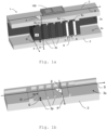
- Figure 1a-1c show a first embodiment of a cooler body 1 according to the invention, together with a part 100 to be cooled, e.g. a power electronic element such as a MOS-FET or IGBT, in particular as part of an automotive electronic circuit.
- a part 100 to be cooled e.g. a power electronic element such as a MOS-FET or IGBT, in particular as part of an automotive electronic circuit.
- the cooler body 1 comprises three main parts, a contact piece 2, a middle piece 4 and a base piece 3.
- the electronic component 100 to be cooled is preferably directly contacted by the contact piece 2, e.g. by a thermal adhesive, a thermal grease or some other interface material with high thermal conductivity.
- the body 1 can be made from metal such as aluminum or copper, whereby the three pieces 2, 3, 4 can be made from metal sheets joined together by soldering or brazing. Joining techniques such as sintering can be used as well wherefore an intermediate sinter layer between metal sheets is used. But preferably, the body 1 is made from thermally conductive but electrically insulating ceramic such as aluminium nitride or aluminium oxide, wherefore advantageously there is no need for an additional electric insulation layer.
- the body 1 preferably is a monolithic body 1.
- a monolithic ceramic body 1 is e.g. formed by manufacturing the three individual parts 2, 3, 4 first as "green” ceramic parts and then sintering all three parts 2, 3, 4 together in one step. Thus, additional assembly steps and thermal interfaces can be avoided.
- the base piece 3 and the contact piece 2 are manufactured from two layers of "green” ceramic instead of one. This would simplify the forming process of the unsintered ceramic. In this case preferably some additional ribs are added to stabilize the structure.
- the contact piece 2 and the base piece 3 are spaced apart by the middle piece 4 in between.
- the contact piece 2 and the base piece 3 embodied as long plates, arranged parallel to each other and extending in a direction S.
- the middle piece 4 is in the example embodied as a block, shorter than the plates 2, 3 in extension direction.
- the middle piece 4 is perforated, the holes 5u, 5d serving a coolant pipes.
- the middle piece 4 comprises a multitude of pipes 5u, 5d arranged parallel to each other.
- the pipes 5d, 5u run from the facing surface 2s of the contact piece 2 to the facing surface 3s of the base piece 3, thereby at least roughly perpendicular to the surface 2s and surface 3s or the angle between the extension direction H of each hole 5u, 5d and the extension direction S of the plates 2, 3 is a right angle (90°).
- the three pieces 2, 3, 4 are layered one above the other, forming in the example a sandwich-like structure.
- the surfaces 2s, 3s are arranged in an angle, e.g. orthogonal, to each other, or are "reversed” parallel to each other, the body 1 then forming a U-like structure.
- the pipes 5d, 5u then are not straight as shown in figure 1a but angled or formed like a "U".
- the base piece 4 is also embodied as a contact piece for thermal contact to the part to be cooled.
- the surfaces 2s, 3s facing the pipes 5d, 5u serve as enclosing surfaces.
- a small gap G is between the middle piece 4 and base piece 3 as well as between middle piece 4 and contact piece 2; or more precisely, there is a gap G between each end of pipes 5u, 5d and each enclosing surface 2s, 3s
- Each gap G is established by protrusions 2p, 3p distributed on each enclosing surface 2s, 3s. Said otherwise, there are protrusions 2p, 3p on the inner side 2s, 3s of contact plate 2 and base plate 3 which serve as distance holders to the pipe piece 4 in the middle.
- the gaps G allow for coolant to enter or exit in the pipes 5u, 5d between the outer pieces 2, 3 and the inner piece 4.
- the protrusions 2p, 3p are designed such that they serve as barriers in the longitudinal direction S. Preferably, they are designed as fin-like structures as shown.
- figure 1b shows only the base plate 3s with fin-like structures 3p on the enclosing surface 3s.
- the fin-like structures 3p are arranged perpendicular to the extension direction S or the angle ⁇ between the extension direction P of each fin 3p and the extension direction S is a right angle or at least roughly 90°.
- the fins 3p are embodied as straight fins. Alternatively, they are wave-like or zig-zag formed. The height of the protrusions 3p define the gap G between enclosing surface 3s and the pipes of the middle piece.
- the fins 3p are arranged successively and spaced (equally) apart from each other on the enclosing surface 3s.
- the distance D between two successive protrusions 3p of a respective piece 2 or 3 is matched to the diameter of the pipes such that is encompasses two successive pipes.
- the contact piece 2 is designed accordingly, however with an offset of (roughly) one pipe (diameter) with respect to the base piece 3, which is explained in more detail below.
- two successive protrusions 2p or 3p together with the part of the respective enclosing surface 2s and 3s in between (and an end face of the middle piece 4) form some sort of chamber or cavity 6, with the end 7 of one pipe 5d as a first opening and the end 8 of the following pipe 5u as a second opening.
- the cavity 6 connects (the end 7 of) one pipe 5u with (the end 8 of) the subsequent pipe 5d.
- the enclosing surfaces 2s, 3s or more particularly the cavities 6 connect the pipes 5u, 5d such that at least two coolant channels result, from a first pipe 5d, running multiple times from the contact piece 2 to the base piece 3 and vice versa through the pipes 5u, 5d and cavities 6 in between the pipes 5u, 5d.
- the protrusions 2p and hence the "upper" cavities 6 at the contact piece 2 are at least one pipe (diameter) offset -preferably offset more than one pipe diameter-with respect to the protrusions 3p and hence the "below” cavities 6 at the base piece 3 in extension direction S to achieve this result of directionally alternating channels.
- Such an alternating channel C is in more detail illustrated in figure 1c .
- Figure 1c illustrates schematically in a 3D-view such an alternating coolant channel C according to the invention, indicated by the bright arrows inside the cooler body 1 (for ease of illustration, only one of the two or more channels is explicitly depicted).
- a coolant enters the cooler body 1 respectively a channel C at an inlet IN (in the figure at the left side) in direction of the extension direction S of the cooler body 1.
- the coolant is first directed at the inner or enclosing surface 2s of the contact piece 2 (indicated by the first two left arrows), where the coolant takes heat from the contact piece 2 respectively the electronics 100.
- the channel C runs the first time “down” from the contact piece 2 to the base piece 3 through a first pipe 5d (indicated by the first dashed arrow from the left).
- first base piece cavity 6, formed by the enclosing surface 3s with two successive protrusions 3p of the base piece 3, the cavity connecting the end of said first pipe 5d with an end of the pipe 5u following in direction S.
- the exit of the first pipe 5d flows into cavity 6 and the base-side opening of the second pipe 5u is exit of cavity 6.
- the channel C thus is redirected about 180° or in other words makes a U-turn (indicated by the first bent arrow).
- the coolant exiting from the first pipe 5d forms an impinging flow on the enclosing surface 2s and enters the second pipe 5u.
- the channel C then runs back or "up” to the contact piece 2 according to the second pipe 5u ((indicated by the upwards continuous arrow).
- the "upwards” pipe 5u leads into contact piece cavity 6 at contact piece 2.
- the coolant again can take up heat from contact piece 2 respectively electronics 100.
- the channel C is redirected about 180° due to cavity 6, leading into a second "downwards" pipe. Said otherwise, the coolant now sinks second time from the contact piece 2 to the base piece 3 through the next pipe of holey middle piece 4. As can be seen, the fin-like structures 2p, 3p of the outer parts 2, 3 separate the coolant between the holes and thus forcing the fluid to return in the next hole.
- the structure of the coolant body 1 as suggest provides in a simple and compact way channels C or coolant flow which alternates multiple times between the contact piece 2 and the base piece 3 between inlet IN and outlet OUT of the cooler body 1.
- the design enables an impact or impingement coolant flow on the contact piece 2 (and base piece 3) and a relatively large contact area between coolant and contact piece 2 resp. surface 2s/3s for heat transfer.
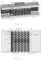
- Figure 2 shows a further embodiment according to the invention. Shown is in a bird's eye view the base piece 2 and a cross section of the middle piece 4.
- the difference between the total number of channels C dtotal ( ⁇ Cn @ 5d n ) at a given pipe row say 5d n and the total number of channels at the same pipe row C utotal ( ⁇ Cn @ 5u n+1 ) is one.
- the difference between the total number of channels C dtotal ( ⁇ Cn @ 5d n ) at a given pipe row say 5d n and the total number of channels of the neighbouring pipe row C utotal ( ⁇ Cn @ 5u n ) is one as well.
- the invention also works with equal number of channels.
- cavities 6a, 6b ... 6n are provided which connect subsequent pipe rows 5u1, 5d2 for redirection of each channel C1...Cn from “upwards” to “downwards”.
- the flow of coolant impinging on the enclosing surface 2s is turned round each time and for each channel C1 ...Cn.
- the holes are offset in direction S. Said otherwise, only each second pipes row 5d1 ...5dN is positioned equally in direction S. Coolant flowing for example into chamber 6a by a pipe of row 5u1 is distributed into the next two nearest pipes of the subsequent row 5d2 (indicated in the figure by continuous arrows Fc). This is equally effected at the base side (indicated in the figure by dashed arrows Fb), i.e. that same effect is observed on the base side.
- a pipe of for example row 5u1 is not part of only one channel (for example C1), but of two channels (C1 and C2). Due to the offset arrangement of pipe rows 5d1...5uN, each channel C1...Cn is allocated to more than one pipe of each row 5d1...5uN. Therefore, the flow F of a coolant liquid is not only alternating “up” and “down” as described with respect to figures 1a-1c , but in addition alternates (in a far more limited way) in "left” and "right” direction.
- This pipe or channel arrangement enables a low-turbulent flow F that allows for a high heat transfer at low pressure-drop which enhances heat absorption or release of the coolant.
Landscapes
- Cooling Or The Like Of Semiconductors Or Solid State Devices (AREA)
- Cooling Or The Like Of Electrical Apparatus (AREA)
Claims (15)
- Corps de refroidisseur (1), en particulier conçu pour refroidir un élément électronique (100), comprenanto une pièce de contact (2) comprenant une surface de contact destinée à venir en contact avec la pièce à refroidir (100),o une pièce de base (3) espacée de la pièce de contact (2) paro une pièce médiane (4) entre la pièce de contact (2) et la pièce de base (3),dans lequelo la pièce médiane (4) comprend des trous séparés formant de multiples rangées de tuyaux de refroidisseur disposés parallèlement (5d, 5u, 5d1, 5u1, 5d2, 5u2-5dN) ;o chaque tuyau s'étend sensiblement de la pièce de contact (2) à la pièce de base (3) eto au moins deux, en particulier au moins cinq, canaux à réfrigérant parallèles (C, C1-Cn) sont formés par des séquences de tuyaux parallèles (5d, 5u) connectés par une surface d'intégration (2s) de la pièce de contact (2) et une surface d'intégration (3s) de la pièce de base (3) de manière à ce que les au moins deux canaux à réfrigérant (C, C1-Cn) aillent de multiples fois de la pièce de contact (2) à la pièce de base (3) et vice versa.
- Corps de refroidisseur (1) selon la revendication 1,
caractérisé en ce que
la surface d'intégration (2s) de la pièce de contact (2) et la surface d'intégration (3s) de la pièce de base (3) comprennent chacune de multiples saillies (2p, 3p) disposées successivement et espacées les unes des autres sur chaque surface d'intégration (2s, 3s), deux saillies successives (2p, 3p) formant avec une partie de la surface d'intégration respective (2s, 3s) une cavité (6, 6a, 6b), la cavité (6, 6a, 6b) connectant un tuyau (5d, 5u) au tuyau suivant (5u, 5d) . - Corps de refroidisseur (1) selon la revendication 2,
caractérisé en ce que
les saillies (2p, 3p) sont des structures de type ailettes en particulier droites, ondulées et/ou en zigzag. - Corps de refroidisseur (1) selon l'une quelconque des revendications précédentes,
caractérisé en ce que
la pièce de base (3) est conçue sous forme d'une autre surface de contact destinée à être en contact avec la pièce à refroidir. - Corps de refroidisseur (1) selon la revendication 2,
caractérisé en ce que
chaque cavité (6a, 6b) connecte les sorties de tous les tuyaux d'une rangée (5u1, 5d2, 5u2-5dN) à toutes les entrées des tuyaux de la rangée consécutive (5d2, 5u2-5dN) . - Corps de refroidisseur (1) selon l'une quelconque des revendications précédentes,
caractérisé en ce que
les rangées de tuyaux consécutives (5d1, 5u1, 5d2, 5u2-5dN) sont décalées les unes des autres. - Corps de refroidisseur (1) selon l'une quelconque des revendications précédentes,
caractérisé en ce que
le corps (1) est composé de céramique, en particulier d'oxyde d'aluminium ou de nitrure d'aluminium. - Corps de refroidisseur (1) selon la revendication 7,
caractérisé en ce que
le corps (1) est un corps monolithique, en particulier formé en frittant des pièces en céramique verte de la pièce de base, de la pièce médiane et de la pièce de contact ensemble en une étape. - Corps de refroidisseur (1) selon l'une quelconque des revendications précédentes,
caractérisé en ce que
le corps (1) est composé de métal, en particulier d'aluminium ou de cuivre. - Corps de refroidisseur (1) selon l'une quelconque des revendications précédentes,
caractérisé en ce que
la pièce de base (3) et la pièce de contact (2) sont conformées sous forme de plaques parallèles, un sens d'extension (S) des plaques définissant en particulier un sens général des canaux (C, C1-Cn). - Corps de refroidisseur (1) selon l'une quelconque des revendications précédentes,
caractérisé en ce queo la surface d'intégration (2s) de la pièce de contact (2) et la surface d'intégration (3s) de la pièce de base (3) sont opposées l'une à l'autre et/ouo les tuyaux (5d, 5u) sont disposés au moins approximativement à la perpendiculaire des surfaces d'intégration (2s, 3s). - Corps de refroidisseur (1) selon l'une quelconque des revendications précédentes,
caractérisé en ce que
la pièce de base (3) et la pièce de contact (2) comprennent des nervures de stabilisation. - Corps de refroidisseur (1) selon l'une quelconque des revendications précédentes,
caractérisé en ce que
la surface de contact de la pièce de contact (2) est conçue pour diriger la fixation à la pièce à refroidir. - Refroidisseur, en particulier refroidisseur à élément électronique, spécialement refroidisseur électronique automobile, comprenant un corps de refroidisseur (1) selon la revendication 1.
- Utilisation d'un corps de refroidisseur (1) selon la revendication 1 dans un système électronique, en particulier dans un système électronique automobile.
Priority Applications (4)
| Application Number | Priority Date | Filing Date | Title |
|---|---|---|---|
| EP19189229.8A EP3772096B1 (fr) | 2019-07-30 | 2019-07-30 | Corps de refroidisseur |
| ES19189229T ES2964171T3 (es) | 2019-07-30 | 2019-07-30 | Cuerpo refrigerador |
| US16/937,387 US11644253B2 (en) | 2019-07-30 | 2020-07-23 | Cooler and cooler body |
| CN202010733899.3A CN112310014B (zh) | 2019-07-30 | 2020-07-24 | 冷却器主体 |
Applications Claiming Priority (1)
| Application Number | Priority Date | Filing Date | Title |
|---|---|---|---|
| EP19189229.8A EP3772096B1 (fr) | 2019-07-30 | 2019-07-30 | Corps de refroidisseur |
Publications (2)
| Publication Number | Publication Date |
|---|---|
| EP3772096A1 EP3772096A1 (fr) | 2021-02-03 |
| EP3772096B1 true EP3772096B1 (fr) | 2023-08-30 |
Family
ID=67544007
Family Applications (1)
| Application Number | Title | Priority Date | Filing Date |
|---|---|---|---|
| EP19189229.8A Active EP3772096B1 (fr) | 2019-07-30 | 2019-07-30 | Corps de refroidisseur |
Country Status (3)
| Country | Link |
|---|---|
| EP (1) | EP3772096B1 (fr) |
| CN (1) | CN112310014B (fr) |
| ES (1) | ES2964171T3 (fr) |
Families Citing this family (1)
| Publication number | Priority date | Publication date | Assignee | Title |
|---|---|---|---|---|
| CN121890261A (zh) | 2023-10-04 | 2026-04-17 | 赛米控丹佛斯有限责任公司 | 用于冷却电子部件的冷却设备及其用途 |
Family Cites Families (7)
| Publication number | Priority date | Publication date | Assignee | Title |
|---|---|---|---|---|
| DE102009004097B4 (de) * | 2008-01-10 | 2018-09-13 | Denso Corporation | Halbleiterkühlstruktur |
| WO2009153735A1 (fr) | 2008-06-18 | 2009-12-23 | Brusa Elektronik Ag | Système de refroidissement, en particulier pour des unités structurelles électroniques |
| KR20120018811A (ko) * | 2009-05-27 | 2012-03-05 | 쿠라미크 엘렉트로닉스 게엠베하 | 냉각 전기 회로 |
| EP3010321B1 (fr) * | 2014-10-14 | 2021-12-01 | Magneti Marelli S.p.A. | Système de refroidissement de liquide pour un composant électronique |
| WO2017059382A1 (fr) * | 2015-09-30 | 2017-04-06 | Microfabrica Inc. | Micro-réseaux de transfert de chaleur, micro-plaques froides, et systèmes de gestion thermique de refroidissement de dispositifs à semi-conducteur, et procédés d'utilisation et de fabrication de ces réseaux, plaques, et systèmes |
| DE102016114303A1 (de) * | 2016-08-02 | 2018-02-08 | Infineon Technologies Ag | Packung mit teilweise gekapseltem Kühlkanal zum Kühlen eines gekapselten Chips |
| CN207896078U (zh) * | 2017-12-15 | 2018-09-21 | 中国振华集团云科电子有限公司 | 一种水冷式散热器及散热系统 |
-
2019
- 2019-07-30 EP EP19189229.8A patent/EP3772096B1/fr active Active
- 2019-07-30 ES ES19189229T patent/ES2964171T3/es active Active
-
2020
- 2020-07-24 CN CN202010733899.3A patent/CN112310014B/zh active Active
Also Published As
| Publication number | Publication date |
|---|---|
| CN112310014B (zh) | 2025-09-16 |
| CN112310014A (zh) | 2021-02-02 |
| ES2964171T3 (es) | 2024-04-04 |
| EP3772096A1 (fr) | 2021-02-03 |
Similar Documents
| Publication | Publication Date | Title |
|---|---|---|
| US8441794B2 (en) | Liquid cooler and method of its manufacture | |
| US8472193B2 (en) | Semiconductor device | |
| JP7818684B2 (ja) | 熱変換装置 | |
| US8528628B2 (en) | Carbon-based apparatus for cooling of electronic devices | |
| US20170156240A1 (en) | Cooled power electronic assembly | |
| JP6094687B2 (ja) | 半導体モジュールおよび電気駆動車両 | |
| EP1790935A2 (fr) | Élément de distribution de flux pour plaque de refroidissement | |
| JP2016119450A (ja) | 熱電変換デバイス及びその応用システム | |
| US20240381567A1 (en) | Cooler for cooling power electronics | |
| US11644253B2 (en) | Cooler and cooler body | |
| JP5135225B2 (ja) | マイクロ熱伝達器ならびに電子素子のための流体冷却器として用いるマイクロ熱伝達器の使用 | |
| CN107084550A (zh) | 半导体制冷组件及冰淇淋机 | |
| JP2006310363A (ja) | パワー半導体装置 | |
| EP3772096B1 (fr) | Corps de refroidisseur | |
| WO2020031753A1 (fr) | Refroidisseur et module à semi-conducteur | |
| US20240414880A1 (en) | Cooling fin of a cooler, through which fluid can flow, for cooling power electronics | |
| CN121058358A (zh) | 用于冷却电子部件的冷却设备 | |
| JP2008235572A (ja) | 電子部品冷却装置 | |
| CN112399771B (zh) | 一种散热装置及基站 | |
| US20260082526A1 (en) | Cooling component for heat dissipation | |
| RU2803414C1 (ru) | Радиатор с эффективным и распределенным теплосъемом | |
| RU2809232C1 (ru) | Радиатор с группами тонких рёбер | |
| US20250151236A1 (en) | Heatsink design with variable effective heat transfer coefficient | |
| JP4293090B2 (ja) | 冷却装置 | |
| CN120957399A (zh) | 变频器功率单元散热装置、变频器功率单元及变频器 |
Legal Events
| Date | Code | Title | Description |
|---|---|---|---|
| PUAI | Public reference made under article 153(3) epc to a published international application that has entered the european phase |
Free format text: ORIGINAL CODE: 0009012 |
|
| STAA | Information on the status of an ep patent application or granted ep patent |
Free format text: STATUS: THE APPLICATION HAS BEEN PUBLISHED |
|
| AK | Designated contracting states |
Kind code of ref document: A1 Designated state(s): AL AT BE BG CH CY CZ DE DK EE ES FI FR GB GR HR HU IE IS IT LI LT LU LV MC MK MT NL NO PL PT RO RS SE SI SK SM TR |
|
| AX | Request for extension of the european patent |
Extension state: BA ME |
|
| STAA | Information on the status of an ep patent application or granted ep patent |
Free format text: STATUS: REQUEST FOR EXAMINATION WAS MADE |
|
| 17P | Request for examination filed |
Effective date: 20210723 |
|
| RBV | Designated contracting states (corrected) |
Designated state(s): AL AT BE BG CH CY CZ DE DK EE ES FI FR GB GR HR HU IE IS IT LI LT LU LV MC MK MT NL NO PL PT RO RS SE SI SK SM TR |
|
| GRAP | Despatch of communication of intention to grant a patent |
Free format text: ORIGINAL CODE: EPIDOSNIGR1 |
|
| STAA | Information on the status of an ep patent application or granted ep patent |
Free format text: STATUS: GRANT OF PATENT IS INTENDED |
|
| INTG | Intention to grant announced |
Effective date: 20230316 |
|
| GRAS | Grant fee paid |
Free format text: ORIGINAL CODE: EPIDOSNIGR3 |
|
| GRAA | (expected) grant |
Free format text: ORIGINAL CODE: 0009210 |
|
| STAA | Information on the status of an ep patent application or granted ep patent |
Free format text: STATUS: THE PATENT HAS BEEN GRANTED |
|
| AK | Designated contracting states |
Kind code of ref document: B1 Designated state(s): AL AT BE BG CH CY CZ DE DK EE ES FI FR GB GR HR HU IE IS IT LI LT LU LV MC MK MT NL NO PL PT RO RS SE SI SK SM TR |
|
| REG | Reference to a national code |
Ref country code: GB Ref legal event code: FG4D |
|
| REG | Reference to a national code |
Ref country code: CH Ref legal event code: EP |
|
| REG | Reference to a national code |
Ref country code: DE Ref legal event code: R096 Ref document number: 602019035995 Country of ref document: DE |
|
| REG | Reference to a national code |
Ref country code: IE Ref legal event code: FG4D |
|
| REG | Reference to a national code |
Ref country code: LT Ref legal event code: MG9D |
|
| REG | Reference to a national code |
Ref country code: NL Ref legal event code: MP Effective date: 20230830 |
|
| REG | Reference to a national code |
Ref country code: AT Ref legal event code: MK05 Ref document number: 1606549 Country of ref document: AT Kind code of ref document: T Effective date: 20230830 |
|
| PG25 | Lapsed in a contracting state [announced via postgrant information from national office to epo] |
Ref country code: GR Free format text: LAPSE BECAUSE OF FAILURE TO SUBMIT A TRANSLATION OF THE DESCRIPTION OR TO PAY THE FEE WITHIN THE PRESCRIBED TIME-LIMIT Effective date: 20231201 |
|
| PG25 | Lapsed in a contracting state [announced via postgrant information from national office to epo] |
Ref country code: IS Free format text: LAPSE BECAUSE OF FAILURE TO SUBMIT A TRANSLATION OF THE DESCRIPTION OR TO PAY THE FEE WITHIN THE PRESCRIBED TIME-LIMIT Effective date: 20231230 |
|
| PG25 | Lapsed in a contracting state [announced via postgrant information from national office to epo] |
Ref country code: SE Free format text: LAPSE BECAUSE OF FAILURE TO SUBMIT A TRANSLATION OF THE DESCRIPTION OR TO PAY THE FEE WITHIN THE PRESCRIBED TIME-LIMIT Effective date: 20230830 Ref country code: RS Free format text: LAPSE BECAUSE OF FAILURE TO SUBMIT A TRANSLATION OF THE DESCRIPTION OR TO PAY THE FEE WITHIN THE PRESCRIBED TIME-LIMIT Effective date: 20230830 Ref country code: NO Free format text: LAPSE BECAUSE OF FAILURE TO SUBMIT A TRANSLATION OF THE DESCRIPTION OR TO PAY THE FEE WITHIN THE PRESCRIBED TIME-LIMIT Effective date: 20231130 Ref country code: LV Free format text: LAPSE BECAUSE OF FAILURE TO SUBMIT A TRANSLATION OF THE DESCRIPTION OR TO PAY THE FEE WITHIN THE PRESCRIBED TIME-LIMIT Effective date: 20230830 Ref country code: LT Free format text: LAPSE BECAUSE OF FAILURE TO SUBMIT A TRANSLATION OF THE DESCRIPTION OR TO PAY THE FEE WITHIN THE PRESCRIBED TIME-LIMIT Effective date: 20230830 Ref country code: IS Free format text: LAPSE BECAUSE OF FAILURE TO SUBMIT A TRANSLATION OF THE DESCRIPTION OR TO PAY THE FEE WITHIN THE PRESCRIBED TIME-LIMIT Effective date: 20231230 Ref country code: HR Free format text: LAPSE BECAUSE OF FAILURE TO SUBMIT A TRANSLATION OF THE DESCRIPTION OR TO PAY THE FEE WITHIN THE PRESCRIBED TIME-LIMIT Effective date: 20230830 Ref country code: GR Free format text: LAPSE BECAUSE OF FAILURE TO SUBMIT A TRANSLATION OF THE DESCRIPTION OR TO PAY THE FEE WITHIN THE PRESCRIBED TIME-LIMIT Effective date: 20231201 Ref country code: FI Free format text: LAPSE BECAUSE OF FAILURE TO SUBMIT A TRANSLATION OF THE DESCRIPTION OR TO PAY THE FEE WITHIN THE PRESCRIBED TIME-LIMIT Effective date: 20230830 Ref country code: AT Free format text: LAPSE BECAUSE OF FAILURE TO SUBMIT A TRANSLATION OF THE DESCRIPTION OR TO PAY THE FEE WITHIN THE PRESCRIBED TIME-LIMIT Effective date: 20230830 |
|
| PG25 | Lapsed in a contracting state [announced via postgrant information from national office to epo] |
Ref country code: PL Free format text: LAPSE BECAUSE OF FAILURE TO SUBMIT A TRANSLATION OF THE DESCRIPTION OR TO PAY THE FEE WITHIN THE PRESCRIBED TIME-LIMIT Effective date: 20230830 Ref country code: NL Free format text: LAPSE BECAUSE OF FAILURE TO SUBMIT A TRANSLATION OF THE DESCRIPTION OR TO PAY THE FEE WITHIN THE PRESCRIBED TIME-LIMIT Effective date: 20230830 |
|
| REG | Reference to a national code |
Ref country code: ES Ref legal event code: FG2A Ref document number: 2964171 Country of ref document: ES Kind code of ref document: T3 Effective date: 20240404 |
|
| PG25 | Lapsed in a contracting state [announced via postgrant information from national office to epo] |
Ref country code: SM Free format text: LAPSE BECAUSE OF FAILURE TO SUBMIT A TRANSLATION OF THE DESCRIPTION OR TO PAY THE FEE WITHIN THE PRESCRIBED TIME-LIMIT Effective date: 20230830 Ref country code: RO Free format text: LAPSE BECAUSE OF FAILURE TO SUBMIT A TRANSLATION OF THE DESCRIPTION OR TO PAY THE FEE WITHIN THE PRESCRIBED TIME-LIMIT Effective date: 20230830 Ref country code: EE Free format text: LAPSE BECAUSE OF FAILURE TO SUBMIT A TRANSLATION OF THE DESCRIPTION OR TO PAY THE FEE WITHIN THE PRESCRIBED TIME-LIMIT Effective date: 20230830 Ref country code: DK Free format text: LAPSE BECAUSE OF FAILURE TO SUBMIT A TRANSLATION OF THE DESCRIPTION OR TO PAY THE FEE WITHIN THE PRESCRIBED TIME-LIMIT Effective date: 20230830 Ref country code: CZ Free format text: LAPSE BECAUSE OF FAILURE TO SUBMIT A TRANSLATION OF THE DESCRIPTION OR TO PAY THE FEE WITHIN THE PRESCRIBED TIME-LIMIT Effective date: 20230830 Ref country code: PT Free format text: LAPSE BECAUSE OF FAILURE TO SUBMIT A TRANSLATION OF THE DESCRIPTION OR TO PAY THE FEE WITHIN THE PRESCRIBED TIME-LIMIT Effective date: 20240102 Ref country code: SK Free format text: LAPSE BECAUSE OF FAILURE TO SUBMIT A TRANSLATION OF THE DESCRIPTION OR TO PAY THE FEE WITHIN THE PRESCRIBED TIME-LIMIT Effective date: 20230830 |
|
| REG | Reference to a national code |
Ref country code: DE Ref legal event code: R097 Ref document number: 602019035995 Country of ref document: DE |
|
| PLBE | No opposition filed within time limit |
Free format text: ORIGINAL CODE: 0009261 |
|
| STAA | Information on the status of an ep patent application or granted ep patent |
Free format text: STATUS: NO OPPOSITION FILED WITHIN TIME LIMIT |
|
| PG25 | Lapsed in a contracting state [announced via postgrant information from national office to epo] |
Ref country code: SI Free format text: LAPSE BECAUSE OF FAILURE TO SUBMIT A TRANSLATION OF THE DESCRIPTION OR TO PAY THE FEE WITHIN THE PRESCRIBED TIME-LIMIT Effective date: 20230830 |
|
| 26N | No opposition filed |
Effective date: 20240603 |
|
| PG25 | Lapsed in a contracting state [announced via postgrant information from national office to epo] |
Ref country code: BG Free format text: LAPSE BECAUSE OF FAILURE TO SUBMIT A TRANSLATION OF THE DESCRIPTION OR TO PAY THE FEE WITHIN THE PRESCRIBED TIME-LIMIT Effective date: 20230830 |
|
| PG25 | Lapsed in a contracting state [announced via postgrant information from national office to epo] |
Ref country code: BG Free format text: LAPSE BECAUSE OF FAILURE TO SUBMIT A TRANSLATION OF THE DESCRIPTION OR TO PAY THE FEE WITHIN THE PRESCRIBED TIME-LIMIT Effective date: 20230830 |
|
| PG25 | Lapsed in a contracting state [announced via postgrant information from national office to epo] |
Ref country code: MC Free format text: LAPSE BECAUSE OF FAILURE TO SUBMIT A TRANSLATION OF THE DESCRIPTION OR TO PAY THE FEE WITHIN THE PRESCRIBED TIME-LIMIT Effective date: 20230830 |
|
| REG | Reference to a national code |
Ref country code: CH Ref legal event code: PL |
|
| REG | Reference to a national code |
Ref country code: DE Ref legal event code: R081 Ref document number: 602019035995 Country of ref document: DE Owner name: BRUSA HYPOWER AG, CH Free format text: FORMER OWNER: BRUSA ELEKTRONIK AG, SENNWALD, CH |
|
| PG25 | Lapsed in a contracting state [announced via postgrant information from national office to epo] |
Ref country code: LU Free format text: LAPSE BECAUSE OF NON-PAYMENT OF DUE FEES Effective date: 20240730 |
|
| PG25 | Lapsed in a contracting state [announced via postgrant information from national office to epo] |
Ref country code: LU Free format text: LAPSE BECAUSE OF NON-PAYMENT OF DUE FEES Effective date: 20240730 |
|
| PG25 | Lapsed in a contracting state [announced via postgrant information from national office to epo] |
Ref country code: CH Free format text: LAPSE BECAUSE OF NON-PAYMENT OF DUE FEES Effective date: 20240731 Ref country code: BE Free format text: LAPSE BECAUSE OF NON-PAYMENT OF DUE FEES Effective date: 20240731 |
|
| REG | Reference to a national code |
Ref country code: BE Ref legal event code: MM Effective date: 20240731 |
|
| REG | Reference to a national code |
Ref country code: GB Ref legal event code: 732E Free format text: REGISTERED BETWEEN 20250626 AND 20250702 |
|
| PG25 | Lapsed in a contracting state [announced via postgrant information from national office to epo] |
Ref country code: IE Free format text: LAPSE BECAUSE OF NON-PAYMENT OF DUE FEES Effective date: 20240730 |
|
| PGFP | Annual fee paid to national office [announced via postgrant information from national office to epo] |
Ref country code: ES Payment date: 20250819 Year of fee payment: 7 |
|
| PGFP | Annual fee paid to national office [announced via postgrant information from national office to epo] |
Ref country code: DE Payment date: 20250723 Year of fee payment: 7 |
|
| PGFP | Annual fee paid to national office [announced via postgrant information from national office to epo] |
Ref country code: TR Payment date: 20250725 Year of fee payment: 7 Ref country code: IT Payment date: 20250731 Year of fee payment: 7 |
|
| PGFP | Annual fee paid to national office [announced via postgrant information from national office to epo] |
Ref country code: GB Payment date: 20250724 Year of fee payment: 7 |
|
| PGFP | Annual fee paid to national office [announced via postgrant information from national office to epo] |
Ref country code: FR Payment date: 20250723 Year of fee payment: 7 |
|
| REG | Reference to a national code |
Ref country code: DE Ref legal event code: R079 Ref document number: 602019035995 Country of ref document: DE Free format text: PREVIOUS MAIN CLASS: H01L0023473000 Ipc: H10W0040470000 |
|
| PG25 | Lapsed in a contracting state [announced via postgrant information from national office to epo] |
Ref country code: CY Free format text: LAPSE BECAUSE OF FAILURE TO SUBMIT A TRANSLATION OF THE DESCRIPTION OR TO PAY THE FEE WITHIN THE PRESCRIBED TIME-LIMIT; INVALID AB INITIO Effective date: 20190730 |
|
| PG25 | Lapsed in a contracting state [announced via postgrant information from national office to epo] |
Ref country code: HU Free format text: LAPSE BECAUSE OF FAILURE TO SUBMIT A TRANSLATION OF THE DESCRIPTION OR TO PAY THE FEE WITHIN THE PRESCRIBED TIME-LIMIT; INVALID AB INITIO Effective date: 20190730 |