EP3772127A1 - Bloc-batterie - Google Patents
Bloc-batterie Download PDFInfo
- Publication number
- EP3772127A1 EP3772127A1 EP20166062.8A EP20166062A EP3772127A1 EP 3772127 A1 EP3772127 A1 EP 3772127A1 EP 20166062 A EP20166062 A EP 20166062A EP 3772127 A1 EP3772127 A1 EP 3772127A1
- Authority
- EP
- European Patent Office
- Prior art keywords
- mounting part
- restraint
- battery pack
- battery
- mounting
- Prior art date
- Legal status (The legal status is an assumption and is not a legal conclusion. Google has not performed a legal analysis and makes no representation as to the accuracy of the status listed.)
- Granted
Links
Images


Classifications
-
- H—ELECTRICITY
- H01—ELECTRIC ELEMENTS
- H01M—PROCESSES OR MEANS, e.g. BATTERIES, FOR THE DIRECT CONVERSION OF CHEMICAL ENERGY INTO ELECTRICAL ENERGY
- H01M10/00—Secondary cells; Manufacture thereof
- H01M10/04—Construction or manufacture in general
- H01M10/0481—Compression means other than compression means for stacks of electrodes and separators
-
- H—ELECTRICITY
- H01—ELECTRIC ELEMENTS
- H01M—PROCESSES OR MEANS, e.g. BATTERIES, FOR THE DIRECT CONVERSION OF CHEMICAL ENERGY INTO ELECTRICAL ENERGY
- H01M50/00—Constructional details or processes of manufacture of the non-active parts of electrochemical cells other than fuel cells, e.g. hybrid cells
- H01M50/20—Mountings; Secondary casings or frames; Racks, modules or packs; Suspension devices; Shock absorbers; Transport or carrying devices; Holders
- H01M50/262—Mountings; Secondary casings or frames; Racks, modules or packs; Suspension devices; Shock absorbers; Transport or carrying devices; Holders with fastening means, e.g. locks
-
- H—ELECTRICITY
- H01—ELECTRIC ELEMENTS
- H01M—PROCESSES OR MEANS, e.g. BATTERIES, FOR THE DIRECT CONVERSION OF CHEMICAL ENERGY INTO ELECTRICAL ENERGY
- H01M50/00—Constructional details or processes of manufacture of the non-active parts of electrochemical cells other than fuel cells, e.g. hybrid cells
- H01M50/20—Mountings; Secondary casings or frames; Racks, modules or packs; Suspension devices; Shock absorbers; Transport or carrying devices; Holders
- H01M50/204—Racks, modules or packs for multiple batteries or multiple cells
-
- H—ELECTRICITY
- H01—ELECTRIC ELEMENTS
- H01M—PROCESSES OR MEANS, e.g. BATTERIES, FOR THE DIRECT CONVERSION OF CHEMICAL ENERGY INTO ELECTRICAL ENERGY
- H01M50/00—Constructional details or processes of manufacture of the non-active parts of electrochemical cells other than fuel cells, e.g. hybrid cells
- H01M50/20—Mountings; Secondary casings or frames; Racks, modules or packs; Suspension devices; Shock absorbers; Transport or carrying devices; Holders
- H01M50/271—Lids or covers for the racks or secondary casings
-
- H—ELECTRICITY
- H01—ELECTRIC ELEMENTS
- H01M—PROCESSES OR MEANS, e.g. BATTERIES, FOR THE DIRECT CONVERSION OF CHEMICAL ENERGY INTO ELECTRICAL ENERGY
- H01M2220/00—Batteries for particular applications
- H01M2220/20—Batteries in motive systems, e.g. vehicle, ship, plane
-
- Y—GENERAL TAGGING OF NEW TECHNOLOGICAL DEVELOPMENTS; GENERAL TAGGING OF CROSS-SECTIONAL TECHNOLOGIES SPANNING OVER SEVERAL SECTIONS OF THE IPC; TECHNICAL SUBJECTS COVERED BY FORMER USPC CROSS-REFERENCE ART COLLECTIONS [XRACs] AND DIGESTS
- Y02—TECHNOLOGIES OR APPLICATIONS FOR MITIGATION OR ADAPTATION AGAINST CLIMATE CHANGE
- Y02E—REDUCTION OF GREENHOUSE GAS [GHG] EMISSIONS, RELATED TO ENERGY GENERATION, TRANSMISSION OR DISTRIBUTION
- Y02E60/00—Enabling technologies; Technologies with a potential or indirect contribution to GHG emissions mitigation
- Y02E60/10—Energy storage using batteries
-
- Y—GENERAL TAGGING OF NEW TECHNOLOGICAL DEVELOPMENTS; GENERAL TAGGING OF CROSS-SECTIONAL TECHNOLOGIES SPANNING OVER SEVERAL SECTIONS OF THE IPC; TECHNICAL SUBJECTS COVERED BY FORMER USPC CROSS-REFERENCE ART COLLECTIONS [XRACs] AND DIGESTS
- Y02—TECHNOLOGIES OR APPLICATIONS FOR MITIGATION OR ADAPTATION AGAINST CLIMATE CHANGE
- Y02P—CLIMATE CHANGE MITIGATION TECHNOLOGIES IN THE PRODUCTION OR PROCESSING OF GOODS
- Y02P70/00—Climate change mitigation technologies in the production process for final industrial or consumer products
- Y02P70/50—Manufacturing or production processes characterised by the final manufactured product
Definitions
- the present disclosure relates to the field of battery technology, particularly to a battery pack.
- rechargeable batteries have been widely used to power vehicles.
- Multiple rechargeable batteries are connected in series, parallel or hybrid to achieve larger capacity or power.
- the embodiments of the disclosure provide a battery pack, the leak tightness of which can be improved.
- the disclosure provides a battery pack which comprises:
- the limit part protrudes from the first mounting part and the second mounting part in a direction away from the battery modules.
- a first restraint component, a second restraint component and a third restraint component constitute three adjacent restraint components and are arranged in sequence along the direction in which the plurality of fixing beams are arranged; wherein the first mounting part of the first restraint component is below the second mounting part of the second restraint component, and the first mounting part of the second restraint component is below the second mounting part of the third restraint component.
- the limit part protrudes from the first mounting part and the second mounting part in a direction away from the battery modules, and the two adjacent restraint components are a fourth restraint component and a fifth restraint component constitute; in the fourth restraint component, there is a first distance L1 between the bottom surface of the first mounting part and the top surface of the limit part, and between the bottom surface of the second mounting part and the top surface of the limit part; in the fifth restraint component, there is a second distance L2 between the bottom surface of the first mounting part and the top surface of the limit part, and between the bottom surface of the second mounting part and the top surface of the limit part; and wherein the fourth restraint component and the fifth restraint component are arranged alternately along the direction in which the plurality of fixing beams are arranged, and the first distance L1 is greater than the second distance L2.
- the thickness of the first mounting part is t, and L1-L2 ⁇ t.
- the battery pack further comprises a plurality of fasteners; wherein the first mounting part is provided with a plurality of first mounting holes spaced along the length direction of the fixing beams, and the second mounting part that is superposed on the first mounting part in the height direction is provided with a plurality of second mounting holes along the length direction of the fixing beams; and each fastener passes through the corresponding second mounting hole and the corresponding first mounting hole in turn and is fixed with the corresponding fixing beam.
- the first mounting part is located below the second mounting part which is overlapped on the first mounting part in the height direction, and the diameter of the second mounting holes is smaller than the diameter of the first mounting holes.
- a stiffener is provided on the limit part.
- the restraint components have a split structure and cover at least part of the surfaces of the corresponding battery modules.
- the battery pack further comprises an outer cover which is disposed on one side of the restraint components away from the battery modules and closes an open end of the box body.
- the battery pack comprises at least one of the following:
- the battery pack by providing restraint components and fixing the restraint components with fixing beams, a stable and effective pressure is provided for each battery module and the degree of expansion and deformation of the battery modules are reduced when the battery modules are expanding. Moreover, by fixing two adjacent restraint components on the same fixing beam, the number of fixing beams can be reduced, the structure of the box body assembly can be simplified, and the width occupied by the fixing beams in the horizontal plane can be reduced.
- the overlapping of the first mounting part and the second mounting part fixed on the same fixing beam in the height direction can further reduce the width occupied by the fixing beams in the horizontal plane, improve the energy density and space utilization of the battery pack and enhance the assembly efficiency of the restraint components and the fixing beams.
- the element when an element is said to be “on” another element, the element may be directly on the other element, or indirectly on the other element with one or more intermediate elements inserted between the two. Further, when an element is said to be “connected to” another element, the element may be directly connected to the other element, or indirectly connected to the other element with one or more intermediate elements inserted between the two. In the following paragraphs, the same reference number represents the same element.
- a plurality of means more than two (including two), similarly, “a plurality of groups” means more than two groups (including two groups), and “a plurality of pieces” means more than two pieces (including two pieces).
- x direction represents the length direction of the battery pack (hereinafter referred to as the length direction); y direction represents the width direction of the battery pack (hereinafter referred to as the width direction); Z direction is perpendicular to the plane formed by the x and y directions and indicates the height direction of the battery pack (hereinafter referred to as the height direction).
- the height direction of the battery pack is parallel to the vertical direction, and the vertical direction mentioned here allows for a certain angle deviation from the theoretical vertical direction. Based on this direction definition, “upper”, “lower”, “top”, and “bottom” are used, all relative to the height direction.
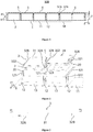
- FIGS. 1 to Figure 12 are schematic diagrams of an embodiment of the battery pack of the disclosure.
- the battery pack 100 comprises: a box body assembly 1, a plurality of battery modules 20 and a plurality of restraint components 3.
- the box body assembly 1 includes a box body 11 and a plurality of fixing beams 12; the box body 11 has an open end, and each of the fixing beams 12 is fixed to the box body 11 and divides the box body 11 into a plurality of containing cavities 13.
- the fixing beams 12 may be fixed on the inner bottom surface or on the side wall of the box body 11.
- the fixing beams 12 may have a solid or hollow structure.
- a weight reduction groove 122 may be provided inside each fixing beam 12.
- the section may be rectangular, trapezoidal or C-shaped, and the upper surface may be arranged as a plane, so as to fix the restraint components on the upper surface of fixing beams 12.
- the restraint components 3 may also be fixed on the side faces of the fixing beams 12.
- Each battery module 20 comprises a plurality of battery cells 2.
- each battery module 20 may have one layer of or a plurality of overlapped layers of battery cells 2 along the height direction.
- at least two or more battery cells 2 can be arranged along the length direction and/or width direction in the battery modules 20.
- Each battery module 20 is correspondingly arranged in each containing cavity 13, one battery module 20 in each containing cavity 13.
- the size of the containing cavity 13 is suitable for the overall size of the corresponding battery module 20.
- each restraint component 3 includes a limit part 31, a first mounting part 32A and a second mounting part 32B, and each limit part 31 covers each battery module 20 correspondingly and may contact or keep a gap with the top battery cell 2.
- the first mounting part 32A and the second mounting part 32B are respectively connected to both sides of the limit part 31 in the direction along which the plurality of fixing beams 12 are arranged, and are respectively fixed to the fixing beam 12 on both sides of the corresponding battery module 20.
- Restraint components 3 cover battery cells 2.
- the first mounting part 32A of one restraint component 3 and the second mounting part 32B of the other restraint component 3 are fixed on the same fixing beam 12 and are overlapped in the height direction.
- the present embodiment of the disclosure provides a stable and effective pressure for each battery module 20 and reduces the degree of expansion and deformation of the battery modules when the battery modules are expanding. Moreover, by fixing two adjacent restraint components 3 on the same fixing beam 12, the number of fixing beams 12 can be reduced; the structure of the box body assembly 1 can be simplified and the width occupied by fixing beams in the horizontal plane can be reduced.
- the overlapping of the first mounting part 32A and the second mounting part 32B fixed on the same fixing beam 12 in the height direction can further reduce the width occupied by the fixing beams 12 in the horizontal plane and allows to lock adjacent battery modules 20 by locking the fasteners required for a single battery module 20 only, which improves the energy density and space utilization of the battery pack, and enhances the assembly efficiency of the restraint components and the fixing beams.
- the separation of two adjacent battery modules by fixing beams 12 is capable of delaying the diffusion of heat to other battery modules 20 when some of the battery modules 20 generate such a large amount of heat in working that thermal runaway occurs, thereby improving the working safety of the battery pack.
- the extension widths of the first mounting part 32A and the second mounting part 32B from limit part 31 are the same, so that the first mounting part 32A and the second mounting part 32B are roughly overlapping, which can further reduce the width occupied by the fixing beams 12 in the horizontal plane, thereby improving the energy density and space utilization of the battery pack.
- the limit part 31 of each restraint component 3 protrudes from the first mounting part 32A and the second mounting part 32B in a direction away from the battery modules 20, and there is a first distance L1 between the bottom surface of the first mounting part 32A and the top surface of the limit part 31 and a second distance L2 between the bottom surface of the second mounting part 32B and the top surface of the limit part 31.
- the first distance L1 is greater than the second distance L2.
- two adjacent restraint components 3 can be installed on the same fixing beam 12, and the first mounting part 32A of one restraint component 3 and the second mounting part 32B of the other restraint component 3 can be overlapped in the height direction.
- all restraint components 3 in the battery pack have the same structure and adopt the same assembly direction, which can reduce the types of parts and reduce the difficulty of assembly.
- the thickness of the first mounting part 32A is t and L1-L2 ⁇ t.
- each fixing beam 12 spaced along the length (x direction) inside the box body 11, and a containing cavity 13 is formed between every two adjacent fixing beams 12; each containing cavity 13 is provided with one battery module 20 and there are a total of six battery modules 20 in the box body 11.
- Each battery module 20 has two layers of battery cells 2 along the height direction, and each layer of battery cell 2 comprises a plurality of battery cells 2 arranged along the width direction (y direction).
- the limit part 31 of each restraint component 3 covers the battery cells 2 of top layer in the corresponding battery module 20.
- fixing beams 12 can also be arranged along the width direction of the box body 11.
- each restraint component 3 As shown in Figure 6 , the installation of three adjacent restraint components 3 is taken as an example, and the installation form of the rest restraint components 3 may be deduced by analogy.
- Three adjacent restraint components 3 are a first restraint component 3A, a second restraint component 3B and a third restraint component 3C, all of which are arranged in sequence along the direction in which the plurality of fixing beams 12 are arranged.
- first mounting part 32A of the first restraint component 3A is below the second mounting part 32B of the second restraint component 3B
- first mounting part 32A of the second restraint component 3B is below the second mounting part 32B of the third restraint component 3C.
- the battery pack of the disclosure may further include a plurality of fasteners 5.
- the first mounting parts 32A are provided with a plurality of first mounting holes 321 at intervals along the length direction of the fixing beams 12.
- the second mounting parts 32B which are overlapped with the first mounting parts 32A in the height direction, are provided with a plurality of second mounting holes 322 at intervals along the length direction of fixing beams 12.
- a plurality of third mounting holes 121 are arranged at intervals along the length direction of the fixing beams 12.
- All fasteners 5 sequentially pass through the second mounting holes 322, the first mounting holes 321 and the third mounting holes 121 at corresponding positions to be fixed with the corresponding fixing beams 12.
- the fasteners 5 may be screws or bolts, etc.
- the first mounting holes 321 and the second mounting holes 322 are unthreaded holes
- the third mounting holes 121 are threaded holes.
- the diameter of the second mounting hole 322 on the second mounting part 32B is smaller than the diameter of the first mounting hole 321 on the first mounting part 32A.
- the first mounting hole 321 with a larger diameter is arranged on the first mounting part 32A, which makes the restraint components 3 and fixing beams 12 less affected by the machining tolerance during assembly and allows easy installation of fasteners 5.
- the second mounting hole 322 with a smaller diameter is arranged on the second mounting part 32B, which can increase the contact area between the fasteners 5 and the second mounting part 32B, so as to improve the connection strength between the fasteners 5 and the second mounting part 32B, and thus improve the fastness of the fixing between two adjacent restraint components 3 and the fixing beams 12.
- the third mounting hole 121 may be provided as an unthreaded hole, and rivet nuts may be embedded in the third mounting hole 121.
- Each rivet nut is of a cylindrical structure and has a rim at one end, and the rim is in contact with the top of the fixing beams 12.
- the opening diameter of the first mounting hole 321 may be made larger than the outer diameter of the rim of the rivet nuts to avoid the rim, so as to increase the contact area between the first mounting part 32A and the fixing beams 12, thereby ensuring uniform stress and avoiding local stress concentration.
- a stiffener 33 is arranged on the limit part 31 to increase the structural strength of the restraint components 3, therefore a more stable and effective pressure is provided for each battery module 20 and the degree of expansion and deformation of the battery module 20 is reduced.
- the stiffener 33 includes a plurality of convex ribs arranged at intervals.
- the convex ribs which may be made by stamping, are not difficult to manufacture and do not increase the weight of the restraint components 3.
- Each of the convex ribs protrudes away from the battery modules 20, which allows to maintain a large contact area between the restraint components 3 and the battery modules 20, and to provide a large pressure for the battery module 20.
- the convex ribs extend in the same direction as the extension direction of fixing beams 12, which can form an even pressure for each battery cell 2 on the top layer of the corresponding battery module 20.
- the extending direction of the convex ribs may also be perpendicular to the extension direction of the fixing beams 12, or the convex ribs may be arranged obliquely.
- each convex rib protrudes toward the direction close to the battery modules 20, which provides a pressure through the stiffener 33 to the battery module 20.
- the convex ribs shown in Figures 8 and 10 can also be combined.
- the stiffener 33 may include a protrusion and/or a recess provided on at least one side surface of the limit part 31, and the protrusion and/or the recess may be formed by machining. For example, when one of the side surfaces of the limit part 31 is provided with a protrusion or recess, the back surface can maintain flat. Further, the stiffener 33 may be a boss or a bump formed by stamping on the limit part 31.
- each restraint component 3 has a split structure and covers at least part of the surface of the corresponding battery module 20.
- restraint components 3 can be split along the length and/or width.
- Figure 12 differs from Figure 5 in that each restraint component 3 covering each single battery module 20 is divided into a first split restraint component 3F and a second split restraint component 3G, where the limit parts 31 of the first split restraint component 3F and the second split restraint component 3G may be spaced apart along the direction in which the plurality of fixing beams 12 are arranged to cover only a part of the surface of the battery modules 20.
- the first split restraint component 3F and the second split restraint component 3G extend continuously along the width direction.
- the advantage of the embodiment is that, affected by the dimensional tolerance of each battery cell 2 in the battery modules 20 and the accuracy of stacking arrangement, the top of each battery cell 2 in the same battery module 20 may also have a height difference, and the use of split-type restraint components 3 makes the processing requirement for the height dimension of the limit part 31 less demanding and allows an easy assembly. Moreover, the split-type restraint components 3 can save materials; In addition, partial coverage of the surface of the battery modules 20 is conducive to the heat dissipation of the battery modules 20.
- the battery pack of the disclosure may further include an outer cover 4 which is disposed on one side of the restraint components 3 away from the battery modules 20 and closes the open end of the box body 11.
- the closing here refers to the tight fitting between the outer cover 4 and the box body 11, which can prevent the external liquid and water vapor from entering the battery pack and improve the safety performance of the battery pack.
- a plurality of restraint components 3 of the battery pack of the above embodiment covers different battery modules 20, and is fixed with the corresponding fixing beam 12, which is equivalent to increasing the fixing points between the restraint components 3 and the box body 11, thereby reducing the span between the fixing points and improving the deformation resistance of the restraint components 3.
- restraint components 3 are not easy to deform and are capable of further providing stable pressure for the battery modules 20 and preventing the battery pack from increasing in the height direction; moreover, the outer cover 4 is not easy to be extruded due to the deformation of the restraint components 3, thereby improving the service life of the battery pack.
- the preset gap L there is a preset gap L between the inner surface of the outer cover 4 and the outer surface of the restraint components 3.
- the preservation of an expansion space for the battery modules 20 makes it possible to prevent the force generated by deformation of the restraint components 3 from being transmitted to the outer cover 4 to force the outer cover 4 to deform; Moreover, even when expansion of the battery modules 20 causes the restraint components 3 to deform so much that the restraint components reach the outer cover 4, the outer cover 4 is capable of also further limiting the deformation of the restraint components 3 and the expansion of the battery modules 20.
- the preset gap ranges from 2 mm to 100 mm.
- first adhesive layer between the bottom of each battery cell 20 and the inner bottom of box body 11; and/or a second adhesive layer is arranged between two adjacent battery cells 20 in the battery module; and/or a third adhesive layer is arranged between the top of each battery module 20 and the restraint components 3.
- the battery pack of the disclosure further comprises: a spacer bar 6; the first mounting part 32A and the second mounting part 32B are located between the spacer bar 6 and the fixing beams 12; the spacer bar 6 may be of a strip structure and is provided with holes to ensure that the fasteners 5 pass through.
- the battery pack of the disclosure may further include a sealing element 7 which is disposed between the outer cover 4 and the shell 11 and may have a strip structure or a rectangular ring structure.
- the sealing element 7 is provided with holes to ensure that fasteners pass through.
- the sealing element may be made of silicone rubber or the like. When the battery pack is used on vehicles, the sealing element is capable of absorbing the vibration transmitted to the battery pack during the operation of the vehicles.
- each of the battery cells 2 includes a shell 21 and an electrode assembly 22 disposed in the shell 21 which can exist in a hexahedral shape or other shapes and has an opening.
- the electrode assembly 22 is housed in the shell 21.
- the opening of the shell 21 is covered with a cover plate assembly 24.
- the cover plate assembly 24 comprises a cover plate 241 and two electrode terminals arranged on the cover plate.
- the two electrode terminals are respectively a first electrode terminal 242 and a second electrode terminal 243.
- the first electrode terminal 242 may be a positive electrode terminal
- the second electrode terminal 243 may be a negative electrode terminal.
- the first electrode terminal 242 may also be a negative electrode terminal
- the second electrode terminal 243 may be a positive electrode terminal.
- Switching sheets 23 are disposed between the cover plate assembly 24 and the electrode assembly 22, and the tabs of the electrode assembly 22 are electrically connected to the electrode terminals on the cover plate 241 through the switching sheets 23.
- two electrode assemblies 22 are disposed in the shell 21 and are stacked along the height direction (z direction) of the battery cells 2, where the height direction of battery cells 2 is consistent with the height direction of the battery pack.
- an electrode assembly 22 may also be provided in the shell 21, or three or more than three electrode assemblies 22 may be provided in the shell 21.
- a plurality of electrode assemblies 22 stack along the height (z direction) of the battery cells 2.
- the electrode assembly 22 comprises a first pole piece 221, a second pole piece 222, and a diaphragm 223 disposed between the first pole piece 221 and the second pole piece 222.
- the first pole piece 221 may be a positive pole piece
- the second pole piece 222 is a negative pole piece.
- the first pole piece 221 may also be a negative pole piece
- the second polar plate 222 may be a positive pole piece.
- the diaphragm 223 is an insulator between the first pole piece 221 and the second pole piece 222.
- the active material of the positive pole piece may be coated onto the coating area of the positive pole piece, and the active material of the negative pole piece may be coated onto the coating area of the negative pole piece.
- the part extending from the coating area of the positive pole piece acts as the positive pole tag.
- the part extending from the coating area of the negative pole piece acts as the negative pole tag.
- the positive pole tag is connected to the positive electrode terminal on cover plate assembly 24 by the positive pole switching sheet, and the negative pole tag is connected to the negative electrode terminal on the cover plate assembly 24 by the negative pole switching sheet.
- the electrode assembly 22 is a winding structure.
- the first pole piece 221, the diaphragm 223 and the second pole piece 222 are strip structures.
- the first pole piece 221, the diaphragm 223 and the second pole piece 222 are stacked and wound two or more turns in turn to form the electrode assembly 22, and the electrode assembly 22 is flat.
- the electrode assembly 22 can be directly wound into a flat shape, or can be wound into a hollow cylindrical structure first, and then flattened into a flat shape after winding.
- Figure 15 is a schematic view showing the outline of the electrode assembly 22, in which the outer surface of the electrode assembly 22 includes two flat surfaces 224 which are opposite to each other along the height direction (z direction) of the battery cells 2.
- the electrode assembly 22 is roughly hexahedral, and the flat surfaces 224 are roughly parallel to the winding axis and are the outer surfaces with the largest area.
- the flat face 224 may be a relatively flat surface and is not necessarily a theoretical flat surface.
- the electrode assembly 22 is of a laminated structure, that is, the electrode assembly 22 includes a plurality of first pole pieces 221 and a plurality of second pole pieces 222, and each diaphragm 223 is arranged between each first pole piece 221 and each second pole piece 222.
- the first pole pieces 221 and the second pole pieces 222 are stacked along the height direction (z direction) of the battery cells 2.
- the electrode assembly 22 will inevitably expand along the thickness direction of the pole pieces, in which case the expansion amount of each pole piece is accumulated, and the accumulated expansion amount in the height direction is larger than in other directions.
- the embodiments of the disclosure can restrain the expansion in the direction where maximum expansion of battery cells 2 occurs by adding fixing points between the restraint components 3 and the box body 11, so as to prevent deformation of the battery pack and improve the service life of battery pack.
- Figure 13 is a schematic structural view of another embodiment of the battery pack of the disclosure.
- the limit part 31 protrudes from the first mounting part 32A and the second mounting part 32B in a direction away from the battery modules 20, and a fourth restraint component 3D and a fifth restraint component 3E constitute two adjacent restraint components.
- the fourth restraint component 3D there is a first distance L1 between the bottom surface of the first mounting part 32A and the top surface of the limit part 31 and between the bottom surface of the second mounting part 32B and the top surface of the limit part 31.
- the fourth restraint component 3D and the fifth restraint component 3E are arranged alternately along the direction in which the plurality of fixing beams 12 are arranged, and the first distance L1 is greater than the second distance L2.
- the four adjacent restraint components 3 are the fourth restraint component 3D, the fifth restraint component 3E, the fourth restraint component 3D and the fifth restraint component 3E respectively, all of which are arranged in the direction in which the plurality of fixing beams 12 are arranged.
- the first mounting part 32A of the first fifth restraint component 3E is located above the second mounting part 32B of the fourth restraint component 3D on the left side.
- the second mounting part 32B of the first fifth restraint component 3E is located above the first mounting part 32A of the fourth restraint component 3D on the right side.
- the first mounting part 32A of the next fifth restraint component 3E is located above the second mounting part 32B of the fourth restraint component 3D on the right, and so on.
- first mounting part 32A and the second mounting part 32B of each fifth restraint component 3E are overlapped on the first mounting part 32A and the second mounting part 32B of the adjacent fourth restraint component 3D on both sides.
- the battery module 20 covered by the fifth restraint component 3E fails, the battery module 20 can be replaced or repaired by simply removing the corresponding fifth restraint component 3E.
- the battery module 20 covered by the fourth restraint component 3D fails, the battery module 20 can be replaced or repaired by removing the fifth restraint components 3E which are adjacent to both sides of the fourth restraint component 3D, thereby improving the convenience and efficiency of repairing the battery modules 20 in the battery pack.
Landscapes
- Chemical & Material Sciences (AREA)
- Chemical Kinetics & Catalysis (AREA)
- Electrochemistry (AREA)
- General Chemical & Material Sciences (AREA)
- Engineering & Computer Science (AREA)
- Manufacturing & Machinery (AREA)
- Battery Mounting, Suspending (AREA)
Applications Claiming Priority (1)
| Application Number | Priority Date | Filing Date | Title |
|---|---|---|---|
| CN201910710351.4A CN111106279B (zh) | 2019-08-02 | 2019-08-02 | 电池包 |
Publications (2)
| Publication Number | Publication Date |
|---|---|
| EP3772127A1 true EP3772127A1 (fr) | 2021-02-03 |
| EP3772127B1 EP3772127B1 (fr) | 2021-12-15 |
Family
ID=70049975
Family Applications (1)
| Application Number | Title | Priority Date | Filing Date |
|---|---|---|---|
| EP20166062.8A Active EP3772127B1 (fr) | 2019-08-02 | 2020-03-26 | Bloc-batterie |
Country Status (3)
| Country | Link |
|---|---|
| US (1) | US11239525B2 (fr) |
| EP (1) | EP3772127B1 (fr) |
| CN (1) | CN111106279B (fr) |
Cited By (3)
| Publication number | Priority date | Publication date | Assignee | Title |
|---|---|---|---|---|
| EP4239766A1 (fr) * | 2022-03-04 | 2023-09-06 | SK On Co., Ltd. | Bloc-batterie |
| EP4468484A1 (fr) * | 2023-05-24 | 2024-11-27 | Volvo Truck Corporation | Ensemble d'accouplement, système de stockage d'énergie, véhicule et procédé |
| EP4439797A3 (fr) * | 2023-03-26 | 2025-01-08 | Samsung SDI Co., Ltd. | Ensemble module de batterie |
Families Citing this family (23)
| Publication number | Priority date | Publication date | Assignee | Title |
|---|---|---|---|---|
| KR20220027160A (ko) * | 2019-06-27 | 2022-03-07 | 컨템포러리 엠퍼렉스 테크놀로지 씨오., 리미티드 | 배터리 팩 및 차량 |
| CN111106282B (zh) | 2019-08-27 | 2021-06-11 | 宁德时代新能源科技股份有限公司 | 电池包 |
| CN111106279B (zh) | 2019-08-02 | 2022-11-08 | 宁德时代新能源科技股份有限公司 | 电池包 |
| CN209963117U (zh) * | 2019-06-27 | 2020-01-17 | 宁德时代新能源科技股份有限公司 | 电池包及车辆 |
| CN112151709B (zh) * | 2019-06-27 | 2025-02-28 | 宁德时代新能源科技股份有限公司 | 电池包及车辆 |
| CN113782901B (zh) * | 2020-05-22 | 2023-12-12 | 比亚迪股份有限公司 | 电池包及电动车 |
| CN113782890B (zh) * | 2020-05-22 | 2024-05-07 | 比亚迪股份有限公司 | 一种电池包及电动车 |
| CN113782899B (zh) * | 2020-05-22 | 2024-05-07 | 比亚迪股份有限公司 | 一种电池包外壳、电池包及电动车 |
| KR20220041428A (ko) * | 2020-09-25 | 2022-04-01 | 주식회사 엘지에너지솔루션 | 전지 모듈, 전지팩 및 이를 포함하는 자동차 |
| KR20220051709A (ko) | 2020-10-19 | 2022-04-26 | 주식회사 엘지에너지솔루션 | 전지 모듈 및 이를 포함하는 전지팩 |
| CN113314790B (zh) * | 2021-05-26 | 2023-01-31 | 荣盛盟固利新能源科技有限公司 | 方舱式电池包 |
| CN113285161A (zh) * | 2021-06-11 | 2021-08-20 | 厦门海辰新能源科技有限公司 | 一种有利于散热可靠性的电池模组、电池包及电动车 |
| EP4145603A4 (fr) * | 2021-07-15 | 2024-01-24 | Contemporary Amperex Technology Co., Limited | Batterie et dispositif consommateur d'énergie |
| CN113571806A (zh) * | 2021-08-19 | 2021-10-29 | 厦门海辰新能源科技有限公司 | 储能系统 |
| WO2023123006A1 (fr) * | 2021-12-29 | 2023-07-06 | 宁德时代新能源科技股份有限公司 | Batterie, appareil électrique, et procédé et dispositif de fabrication de batterie |
| US20240088499A1 (en) * | 2022-09-13 | 2024-03-14 | Ford Global Technologies, Llc | Traction battery pack assembly having a barrier between cell stacks |
| EP4586381A4 (fr) * | 2022-09-15 | 2026-01-14 | Contemporary Amperex Technology Hong Kong Ltd | Batterie et dispositif électrique |
| CN116653879A (zh) * | 2022-12-01 | 2023-08-29 | 奥动新能源汽车科技有限公司 | 一种换电车辆位置调整装置 |
| CN220138575U (zh) * | 2023-06-26 | 2023-12-05 | 欣旺达动力科技股份有限公司 | 电池包 |
| CN116722293B (zh) * | 2023-08-07 | 2023-11-10 | 上海汽车集团股份有限公司 | 用于车辆的电池包组件 |
| KR20260021056A (ko) * | 2023-08-31 | 2026-02-12 | 컨템포러리 엠퍼렉스 테크놀로지 씨오., 리미티드 | 배터리 및 전기기기 |
| CN222562823U (zh) * | 2024-02-01 | 2025-03-04 | 宁德时代新能源科技股份有限公司 | 电池及用电装置 |
| CN120581794B (zh) * | 2025-08-04 | 2025-11-07 | 宁德时代新能源科技股份有限公司 | 电池装置及用电装置 |
Citations (4)
| Publication number | Priority date | Publication date | Assignee | Title |
|---|---|---|---|---|
| CN106601958A (zh) * | 2017-02-13 | 2017-04-26 | 深圳市沃特玛电池有限公司 | 一种电池模组的固定结构 |
| CN207558892U (zh) * | 2017-12-25 | 2018-06-29 | 宁德时代新能源科技股份有限公司 | 电池模组及电池包 |
| CN209000986U (zh) * | 2018-11-13 | 2019-06-18 | 宁德时代新能源科技股份有限公司 | 一种输出极底座、电池模组及电池包 |
| EP3506386A1 (fr) * | 2017-12-28 | 2019-07-03 | Contemporary Amperex Technology Co., Limited | Coque, module de batterie et block-batterie |
Family Cites Families (23)
| Publication number | Priority date | Publication date | Assignee | Title |
|---|---|---|---|---|
| JP5343048B2 (ja) * | 2010-07-29 | 2013-11-13 | 日立ビークルエナジー株式会社 | 蓄電モジュールおよび蓄電装置 |
| CN202178305U (zh) * | 2011-07-19 | 2012-03-28 | 惠州比亚迪电池有限公司 | 一种电动汽车电源模块 |
| CN202268412U (zh) * | 2011-09-28 | 2012-06-06 | 上海比亚迪有限公司 | 一种车用动力电池包 |
| CN202434596U (zh) * | 2011-11-25 | 2012-09-12 | 深圳市比亚迪锂电池有限公司 | 一种动力电池包 |
| JP6255970B2 (ja) * | 2013-12-16 | 2018-01-10 | 日産自動車株式会社 | 電池システム |
| JP6450966B2 (ja) | 2014-10-22 | 2019-01-16 | 三菱自動車工業株式会社 | 電池パック |
| KR20160091124A (ko) * | 2015-01-23 | 2016-08-02 | 삼성에스디아이 주식회사 | 이차전지 유닛을 수납하는 하우징을 구비하는 배터리 모듈 |
| JP6616103B2 (ja) * | 2015-05-21 | 2019-12-04 | 株式会社エンビジョンAescジャパン | 車両用バッテリパックにおけるバッテリモジュール支持構造 |
| CN204857805U (zh) * | 2015-07-16 | 2015-12-09 | 宁德时代新能源科技有限公司 | 一种电池箱结构 |
| CN205159401U (zh) * | 2015-11-27 | 2016-04-13 | 国联汽车动力电池研究院有限责任公司 | 一种搭接式动力电池模组 |
| CN205488244U (zh) * | 2016-01-05 | 2016-08-17 | 宁德时代新能源科技股份有限公司 | 电池模组及电池包 |
| CN206148486U (zh) * | 2016-08-31 | 2017-05-03 | 多氟多化工股份有限公司 | 一种电池箱 |
| KR102317506B1 (ko) * | 2017-04-10 | 2021-10-26 | 삼성에스디아이 주식회사 | 배터리 팩 |
| CN110959224A (zh) * | 2017-07-31 | 2020-04-03 | 松下知识产权经营株式会社 | 电池模块、电池组以及合并电池组 |
| CN107658401A (zh) * | 2017-09-27 | 2018-02-02 | 中聚(杭州)新能源科技有限公司 | 具有无端板电池模组的动力电池箱 |
| CN108832039B (zh) * | 2018-06-20 | 2023-11-14 | 北京联动天翼科技股份有限公司 | 铝壳电芯固定支架 |
| CN208336326U (zh) * | 2018-06-20 | 2019-01-04 | 宁德时代新能源科技股份有限公司 | 固定支架及电池包 |
| CN109256511A (zh) * | 2018-11-16 | 2019-01-22 | 爱驰汽车有限公司 | 电池包 |
| CN209104243U (zh) * | 2018-12-29 | 2019-07-12 | 蜂巢能源科技有限公司 | 电池包的电池模组以及电池包 |
| CN111106279B (zh) | 2019-08-02 | 2022-11-08 | 宁德时代新能源科技股份有限公司 | 电池包 |
| CN209963117U (zh) | 2019-06-27 | 2020-01-17 | 宁德时代新能源科技股份有限公司 | 电池包及车辆 |
| CN209963118U (zh) | 2019-06-27 | 2020-01-17 | 宁德时代新能源科技股份有限公司 | 电池包及车辆 |
| CN111106282B (zh) | 2019-08-27 | 2021-06-11 | 宁德时代新能源科技股份有限公司 | 电池包 |
-
2019
- 2019-08-02 CN CN201910710351.4A patent/CN111106279B/zh active Active
-
2020
- 2020-03-26 EP EP20166062.8A patent/EP3772127B1/fr active Active
- 2020-04-02 US US16/838,066 patent/US11239525B2/en active Active
Patent Citations (4)
| Publication number | Priority date | Publication date | Assignee | Title |
|---|---|---|---|---|
| CN106601958A (zh) * | 2017-02-13 | 2017-04-26 | 深圳市沃特玛电池有限公司 | 一种电池模组的固定结构 |
| CN207558892U (zh) * | 2017-12-25 | 2018-06-29 | 宁德时代新能源科技股份有限公司 | 电池模组及电池包 |
| EP3506386A1 (fr) * | 2017-12-28 | 2019-07-03 | Contemporary Amperex Technology Co., Limited | Coque, module de batterie et block-batterie |
| CN209000986U (zh) * | 2018-11-13 | 2019-06-18 | 宁德时代新能源科技股份有限公司 | 一种输出极底座、电池模组及电池包 |
Cited By (4)
| Publication number | Priority date | Publication date | Assignee | Title |
|---|---|---|---|---|
| EP4239766A1 (fr) * | 2022-03-04 | 2023-09-06 | SK On Co., Ltd. | Bloc-batterie |
| EP4439797A3 (fr) * | 2023-03-26 | 2025-01-08 | Samsung SDI Co., Ltd. | Ensemble module de batterie |
| EP4468484A1 (fr) * | 2023-05-24 | 2024-11-27 | Volvo Truck Corporation | Ensemble d'accouplement, système de stockage d'énergie, véhicule et procédé |
| EP4468483A1 (fr) * | 2023-05-24 | 2024-11-27 | Volvo Truck Corporation | Ensemble d'accouplement, système de stockage d'énergie, véhicule et procédé |
Also Published As
| Publication number | Publication date |
|---|---|
| CN111106279B (zh) | 2022-11-08 |
| CN111106279A (zh) | 2020-05-05 |
| EP3772127B1 (fr) | 2021-12-15 |
| US20210036278A1 (en) | 2021-02-04 |
| US11239525B2 (en) | 2022-02-01 |
Similar Documents
| Publication | Publication Date | Title |
|---|---|---|
| EP3772127B1 (fr) | Bloc-batterie | |
| US11894510B2 (en) | Battery pack and vehicle | |
| EP3151307B1 (fr) | Module de batterie et bloc-batterie le comprenant | |
| US12176559B2 (en) | Battery cell assembly, battery module, and battery pack | |
| US11251493B2 (en) | Battery pack | |
| KR100896133B1 (ko) | 향상된 안전성의 이차전지 | |
| EP3525255A1 (fr) | Module de batterie | |
| WO2020259434A1 (fr) | Bloc-batterie et véhicule | |
| US20210143505A1 (en) | Energy storage apparatus | |
| KR101530803B1 (ko) | 이차 전지 | |
| WO2020259139A1 (fr) | Bloc-batterie, procédé de fabrication de bloc-batterie et véhicule | |
| KR20130069476A (ko) | 신뢰성이 향상된 전지모듈 어셈블리 및 이를 포함하는 중대형 전지팩 | |
| KR20170062845A (ko) | 구성이 간소화된 단위모듈을 포함하고 있는 전지모듈 | |
| US20210151722A1 (en) | Battery pack | |
| KR20250103694A (ko) | 배터리의 장착 장치, 배터리 및 전기기기 | |
| JP6247486B2 (ja) | 組電池 | |
| KR102812545B1 (ko) | 전지, 전기 장치, 전지의 제조 방법 및 제조 설비 | |
| EP3399569B1 (fr) | Cellule de batterie comprenant un boîtier de batterie comprenant une partie de réception et une rainure de fil d'électrode | |
| JP6031388B2 (ja) | 組電池 | |
| US12620662B2 (en) | Battery pack, vehicle, and energy storage system | |
| EP4618286A1 (fr) | Bloc-batterie et dispositif le comprenant | |
| US20230299406A1 (en) | Battery pack, vehicle, and energy storage system | |
| JP2025519189A (ja) | 電池モジュールおよびこれを含む電池パック | |
| CN120810129A (zh) | 电池系统和包括其的电动车辆 | |
| KR20260055885A (ko) | 배터리 팩 |
Legal Events
| Date | Code | Title | Description |
|---|---|---|---|
| PUAI | Public reference made under article 153(3) epc to a published international application that has entered the european phase |
Free format text: ORIGINAL CODE: 0009012 |
|
| STAA | Information on the status of an ep patent application or granted ep patent |
Free format text: STATUS: THE APPLICATION HAS BEEN PUBLISHED |
|
| AK | Designated contracting states |
Kind code of ref document: A1 Designated state(s): AL AT BE BG CH CY CZ DE DK EE ES FI FR GB GR HR HU IE IS IT LI LT LU LV MC MK MT NL NO PL PT RO RS SE SI SK SM TR |
|
| AX | Request for extension of the european patent |
Extension state: BA ME |
|
| STAA | Information on the status of an ep patent application or granted ep patent |
Free format text: STATUS: REQUEST FOR EXAMINATION WAS MADE |
|
| 17P | Request for examination filed |
Effective date: 20210409 |
|
| RBV | Designated contracting states (corrected) |
Designated state(s): AL AT BE BG CH CY CZ DE DK EE ES FI FR GB GR HR HU IE IS IT LI LT LU LV MC MK MT NL NO PL PT RO RS SE SI SK SM TR |
|
| REG | Reference to a national code |
Ref country code: DE Ref legal event code: R079 Ref document number: 602020001264 Country of ref document: DE Free format text: PREVIOUS MAIN CLASS: H01M0010040000 Ipc: H01M0050200000 |
|
| GRAP | Despatch of communication of intention to grant a patent |
Free format text: ORIGINAL CODE: EPIDOSNIGR1 |
|
| STAA | Information on the status of an ep patent application or granted ep patent |
Free format text: STATUS: GRANT OF PATENT IS INTENDED |
|
| RIC1 | Information provided on ipc code assigned before grant |
Ipc: H01M 50/20 20210101AFI20210625BHEP Ipc: H01M 10/04 20060101ALI20210625BHEP |
|
| INTG | Intention to grant announced |
Effective date: 20210713 |
|
| GRAS | Grant fee paid |
Free format text: ORIGINAL CODE: EPIDOSNIGR3 |
|
| GRAA | (expected) grant |
Free format text: ORIGINAL CODE: 0009210 |
|
| STAA | Information on the status of an ep patent application or granted ep patent |
Free format text: STATUS: THE PATENT HAS BEEN GRANTED |
|
| AK | Designated contracting states |
Kind code of ref document: B1 Designated state(s): AL AT BE BG CH CY CZ DE DK EE ES FI FR GB GR HR HU IE IS IT LI LT LU LV MC MK MT NL NO PL PT RO RS SE SI SK SM TR |
|
| REG | Reference to a national code |
Ref country code: GB Ref legal event code: FG4D Ref country code: CH Ref legal event code: EP |
|
| REG | Reference to a national code |
Ref country code: IE Ref legal event code: FG4D Ref country code: DE Ref legal event code: R096 Ref document number: 602020001264 Country of ref document: DE |
|
| REG | Reference to a national code |
Ref country code: AT Ref legal event code: REF Ref document number: 1456168 Country of ref document: AT Kind code of ref document: T Effective date: 20220115 |
|
| REG | Reference to a national code |
Ref country code: LT Ref legal event code: MG9D |
|
| REG | Reference to a national code |
Ref country code: NL Ref legal event code: MP Effective date: 20211215 |
|
| PG25 | Lapsed in a contracting state [announced via postgrant information from national office to epo] |
Ref country code: RS Free format text: LAPSE BECAUSE OF FAILURE TO SUBMIT A TRANSLATION OF THE DESCRIPTION OR TO PAY THE FEE WITHIN THE PRESCRIBED TIME-LIMIT Effective date: 20211215 Ref country code: LT Free format text: LAPSE BECAUSE OF FAILURE TO SUBMIT A TRANSLATION OF THE DESCRIPTION OR TO PAY THE FEE WITHIN THE PRESCRIBED TIME-LIMIT Effective date: 20211215 Ref country code: FI Free format text: LAPSE BECAUSE OF FAILURE TO SUBMIT A TRANSLATION OF THE DESCRIPTION OR TO PAY THE FEE WITHIN THE PRESCRIBED TIME-LIMIT Effective date: 20211215 Ref country code: BG Free format text: LAPSE BECAUSE OF FAILURE TO SUBMIT A TRANSLATION OF THE DESCRIPTION OR TO PAY THE FEE WITHIN THE PRESCRIBED TIME-LIMIT Effective date: 20220315 |
|
| REG | Reference to a national code |
Ref country code: AT Ref legal event code: MK05 Ref document number: 1456168 Country of ref document: AT Kind code of ref document: T Effective date: 20211215 |
|
| PG25 | Lapsed in a contracting state [announced via postgrant information from national office to epo] |
Ref country code: SE Free format text: LAPSE BECAUSE OF FAILURE TO SUBMIT A TRANSLATION OF THE DESCRIPTION OR TO PAY THE FEE WITHIN THE PRESCRIBED TIME-LIMIT Effective date: 20211215 Ref country code: NO Free format text: LAPSE BECAUSE OF FAILURE TO SUBMIT A TRANSLATION OF THE DESCRIPTION OR TO PAY THE FEE WITHIN THE PRESCRIBED TIME-LIMIT Effective date: 20220315 Ref country code: LV Free format text: LAPSE BECAUSE OF FAILURE TO SUBMIT A TRANSLATION OF THE DESCRIPTION OR TO PAY THE FEE WITHIN THE PRESCRIBED TIME-LIMIT Effective date: 20211215 Ref country code: HR Free format text: LAPSE BECAUSE OF FAILURE TO SUBMIT A TRANSLATION OF THE DESCRIPTION OR TO PAY THE FEE WITHIN THE PRESCRIBED TIME-LIMIT Effective date: 20211215 Ref country code: GR Free format text: LAPSE BECAUSE OF FAILURE TO SUBMIT A TRANSLATION OF THE DESCRIPTION OR TO PAY THE FEE WITHIN THE PRESCRIBED TIME-LIMIT Effective date: 20220316 |
|
| PG25 | Lapsed in a contracting state [announced via postgrant information from national office to epo] |
Ref country code: NL Free format text: LAPSE BECAUSE OF FAILURE TO SUBMIT A TRANSLATION OF THE DESCRIPTION OR TO PAY THE FEE WITHIN THE PRESCRIBED TIME-LIMIT Effective date: 20211215 |
|
| PG25 | Lapsed in a contracting state [announced via postgrant information from national office to epo] |
Ref country code: SM Free format text: LAPSE BECAUSE OF FAILURE TO SUBMIT A TRANSLATION OF THE DESCRIPTION OR TO PAY THE FEE WITHIN THE PRESCRIBED TIME-LIMIT Effective date: 20211215 Ref country code: SK Free format text: LAPSE BECAUSE OF FAILURE TO SUBMIT A TRANSLATION OF THE DESCRIPTION OR TO PAY THE FEE WITHIN THE PRESCRIBED TIME-LIMIT Effective date: 20211215 Ref country code: RO Free format text: LAPSE BECAUSE OF FAILURE TO SUBMIT A TRANSLATION OF THE DESCRIPTION OR TO PAY THE FEE WITHIN THE PRESCRIBED TIME-LIMIT Effective date: 20211215 Ref country code: PT Free format text: LAPSE BECAUSE OF FAILURE TO SUBMIT A TRANSLATION OF THE DESCRIPTION OR TO PAY THE FEE WITHIN THE PRESCRIBED TIME-LIMIT Effective date: 20220418 Ref country code: ES Free format text: LAPSE BECAUSE OF FAILURE TO SUBMIT A TRANSLATION OF THE DESCRIPTION OR TO PAY THE FEE WITHIN THE PRESCRIBED TIME-LIMIT Effective date: 20211215 Ref country code: EE Free format text: LAPSE BECAUSE OF FAILURE TO SUBMIT A TRANSLATION OF THE DESCRIPTION OR TO PAY THE FEE WITHIN THE PRESCRIBED TIME-LIMIT Effective date: 20211215 Ref country code: CZ Free format text: LAPSE BECAUSE OF FAILURE TO SUBMIT A TRANSLATION OF THE DESCRIPTION OR TO PAY THE FEE WITHIN THE PRESCRIBED TIME-LIMIT Effective date: 20211215 |
|
| PG25 | Lapsed in a contracting state [announced via postgrant information from national office to epo] |
Ref country code: PL Free format text: LAPSE BECAUSE OF FAILURE TO SUBMIT A TRANSLATION OF THE DESCRIPTION OR TO PAY THE FEE WITHIN THE PRESCRIBED TIME-LIMIT Effective date: 20211215 Ref country code: AT Free format text: LAPSE BECAUSE OF FAILURE TO SUBMIT A TRANSLATION OF THE DESCRIPTION OR TO PAY THE FEE WITHIN THE PRESCRIBED TIME-LIMIT Effective date: 20211215 |
|
| REG | Reference to a national code |
Ref country code: DE Ref legal event code: R097 Ref document number: 602020001264 Country of ref document: DE |
|
| PG25 | Lapsed in a contracting state [announced via postgrant information from national office to epo] |
Ref country code: IS Free format text: LAPSE BECAUSE OF FAILURE TO SUBMIT A TRANSLATION OF THE DESCRIPTION OR TO PAY THE FEE WITHIN THE PRESCRIBED TIME-LIMIT Effective date: 20220415 |
|
| PLBE | No opposition filed within time limit |
Free format text: ORIGINAL CODE: 0009261 |
|
| STAA | Information on the status of an ep patent application or granted ep patent |
Free format text: STATUS: NO OPPOSITION FILED WITHIN TIME LIMIT |
|
| PG25 | Lapsed in a contracting state [announced via postgrant information from national office to epo] |
Ref country code: MC Free format text: LAPSE BECAUSE OF FAILURE TO SUBMIT A TRANSLATION OF THE DESCRIPTION OR TO PAY THE FEE WITHIN THE PRESCRIBED TIME-LIMIT Effective date: 20211215 Ref country code: DK Free format text: LAPSE BECAUSE OF FAILURE TO SUBMIT A TRANSLATION OF THE DESCRIPTION OR TO PAY THE FEE WITHIN THE PRESCRIBED TIME-LIMIT Effective date: 20211215 Ref country code: AL Free format text: LAPSE BECAUSE OF FAILURE TO SUBMIT A TRANSLATION OF THE DESCRIPTION OR TO PAY THE FEE WITHIN THE PRESCRIBED TIME-LIMIT Effective date: 20211215 |
|
| 26N | No opposition filed |
Effective date: 20220916 |
|
| REG | Reference to a national code |
Ref country code: BE Ref legal event code: MM Effective date: 20220331 |
|
| PG25 | Lapsed in a contracting state [announced via postgrant information from national office to epo] |
Ref country code: LU Free format text: LAPSE BECAUSE OF NON-PAYMENT OF DUE FEES Effective date: 20220326 Ref country code: IE Free format text: LAPSE BECAUSE OF NON-PAYMENT OF DUE FEES Effective date: 20220326 |
|
| PG25 | Lapsed in a contracting state [announced via postgrant information from national office to epo] |
Ref country code: BE Free format text: LAPSE BECAUSE OF NON-PAYMENT OF DUE FEES Effective date: 20220331 |
|
| PG25 | Lapsed in a contracting state [announced via postgrant information from national office to epo] |
Ref country code: IT Free format text: LAPSE BECAUSE OF FAILURE TO SUBMIT A TRANSLATION OF THE DESCRIPTION OR TO PAY THE FEE WITHIN THE PRESCRIBED TIME-LIMIT Effective date: 20211215 |
|
| P01 | Opt-out of the competence of the unified patent court (upc) registered |
Effective date: 20230516 |
|
| REG | Reference to a national code |
Ref country code: CH Ref legal event code: PL |
|
| PG25 | Lapsed in a contracting state [announced via postgrant information from national office to epo] |
Ref country code: LI Free format text: LAPSE BECAUSE OF NON-PAYMENT OF DUE FEES Effective date: 20230331 Ref country code: CH Free format text: LAPSE BECAUSE OF NON-PAYMENT OF DUE FEES Effective date: 20230331 |
|
| PG25 | Lapsed in a contracting state [announced via postgrant information from national office to epo] |
Ref country code: MK Free format text: LAPSE BECAUSE OF FAILURE TO SUBMIT A TRANSLATION OF THE DESCRIPTION OR TO PAY THE FEE WITHIN THE PRESCRIBED TIME-LIMIT Effective date: 20211215 Ref country code: CY Free format text: LAPSE BECAUSE OF FAILURE TO SUBMIT A TRANSLATION OF THE DESCRIPTION OR TO PAY THE FEE WITHIN THE PRESCRIBED TIME-LIMIT Effective date: 20211215 |
|
| PG25 | Lapsed in a contracting state [announced via postgrant information from national office to epo] |
Ref country code: HU Free format text: LAPSE BECAUSE OF FAILURE TO SUBMIT A TRANSLATION OF THE DESCRIPTION OR TO PAY THE FEE WITHIN THE PRESCRIBED TIME-LIMIT; INVALID AB INITIO Effective date: 20200326 |
|
| REG | Reference to a national code |
Ref country code: DE Ref legal event code: R081 Ref document number: 602020001264 Country of ref document: DE Owner name: CONTEMPORARY AMPEREX TECHNOLOGY (HONG KONG) LI, HK Free format text: FORMER OWNER: CONTEMPORARY AMPEREX TECHNOLOGY CO., LIMITED, NINGDE CITY, FUJIAN, CN |
|
| REG | Reference to a national code |
Ref country code: GB Ref legal event code: 732E Free format text: REGISTERED BETWEEN 20240822 AND 20240828 |
|
| PG25 | Lapsed in a contracting state [announced via postgrant information from national office to epo] |
Ref country code: MT Free format text: LAPSE BECAUSE OF FAILURE TO SUBMIT A TRANSLATION OF THE DESCRIPTION OR TO PAY THE FEE WITHIN THE PRESCRIBED TIME-LIMIT Effective date: 20211215 |
|
| PG25 | Lapsed in a contracting state [announced via postgrant information from national office to epo] |
Ref country code: TR Free format text: LAPSE BECAUSE OF FAILURE TO SUBMIT A TRANSLATION OF THE DESCRIPTION OR TO PAY THE FEE WITHIN THE PRESCRIBED TIME-LIMIT Effective date: 20211215 |
|
| PGFP | Annual fee paid to national office [announced via postgrant information from national office to epo] |
Ref country code: FR Payment date: 20251231 Year of fee payment: 7 |
|
| PG25 | Lapsed in a contracting state [announced via postgrant information from national office to epo] |
Ref country code: SI Free format text: LAPSE BECAUSE OF FAILURE TO SUBMIT A TRANSLATION OF THE DESCRIPTION OR TO PAY THE FEE WITHIN THE PRESCRIBED TIME-LIMIT Effective date: 20211215 |
|
| PGFP | Annual fee paid to national office [announced via postgrant information from national office to epo] |
Ref country code: GB Payment date: 20260106 Year of fee payment: 7 |
|
| PGFP | Annual fee paid to national office [announced via postgrant information from national office to epo] |
Ref country code: DE Payment date: 20260102 Year of fee payment: 7 |