EP3772190B1 - Kommunikationsvorrichtung und antenne - Google Patents
Kommunikationsvorrichtung und antenne Download PDFInfo
- Publication number
- EP3772190B1 EP3772190B1 EP20186215.8A EP20186215A EP3772190B1 EP 3772190 B1 EP3772190 B1 EP 3772190B1 EP 20186215 A EP20186215 A EP 20186215A EP 3772190 B1 EP3772190 B1 EP 3772190B1
- Authority
- EP
- European Patent Office
- Prior art keywords
- antenna
- communication apparatus
- base
- satellite
- antenna elements
- Prior art date
- Legal status (The legal status is an assumption and is not a legal conclusion. Google has not performed a legal analysis and makes no representation as to the accuracy of the status listed.)
- Active
Links
Images


Classifications
-
- H—ELECTRICITY
- H01—ELECTRIC ELEMENTS
- H01Q—ANTENNAS, i.e. RADIO AERIALS
- H01Q21/00—Antenna arrays or systems
- H01Q21/06—Arrays of individually energised antenna units similarly polarised and spaced apart
- H01Q21/20—Arrays of individually energised antenna units similarly polarised and spaced apart the units being spaced along or adjacent to a curvilinear path
-
- H—ELECTRICITY
- H04—ELECTRIC COMMUNICATION TECHNIQUE
- H04B—TRANSMISSION
- H04B7/00—Radio transmission systems, i.e. using radiation field
- H04B7/14—Relay systems
- H04B7/15—Active relay systems
- H04B7/185—Space-based or airborne stations; Stations for satellite systems
- H04B7/18502—Airborne stations
- H04B7/18506—Communications with or from aircraft, i.e. aeronautical mobile service
- H04B7/18508—Communications with or from aircraft, i.e. aeronautical mobile service with satellite system used as relay, i.e. aeronautical mobile satellite service
-
- H—ELECTRICITY
- H01—ELECTRIC ELEMENTS
- H01Q—ANTENNAS, i.e. RADIO AERIALS
- H01Q1/00—Details of, or arrangements associated with, antennas
- H01Q1/52—Means for reducing coupling between antennas; Means for reducing coupling between an antenna and another structure
- H01Q1/521—Means for reducing coupling between antennas; Means for reducing coupling between an antenna and another structure reducing the coupling between adjacent antennas
- H01Q1/523—Means for reducing coupling between antennas; Means for reducing coupling between an antenna and another structure reducing the coupling between adjacent antennas between antennas of an array
-
- H—ELECTRICITY
- H01—ELECTRIC ELEMENTS
- H01Q—ANTENNAS, i.e. RADIO AERIALS
- H01Q9/00—Electrically-short antennas having dimensions not more than twice the operating wavelength and consisting of conductive active radiating elements
- H01Q9/04—Resonant antennas
- H01Q9/0407—Substantially flat resonant element parallel to ground plane, e.g. patch antenna
-
- H—ELECTRICITY
- H04—ELECTRIC COMMUNICATION TECHNIQUE
- H04B—TRANSMISSION
- H04B7/00—Radio transmission systems, i.e. using radiation field
- H04B7/02—Diversity systems; Multi-antenna system, i.e. transmission or reception using multiple antennas
- H04B7/04—Diversity systems; Multi-antenna system, i.e. transmission or reception using multiple antennas using two or more spaced independent antennas
- H04B7/06—Diversity systems; Multi-antenna system, i.e. transmission or reception using multiple antennas using two or more spaced independent antennas at the transmitting station
- H04B7/0613—Diversity systems; Multi-antenna system, i.e. transmission or reception using multiple antennas using two or more spaced independent antennas at the transmitting station using simultaneous transmission
- H04B7/0615—Diversity systems; Multi-antenna system, i.e. transmission or reception using multiple antennas using two or more spaced independent antennas at the transmitting station using simultaneous transmission of weighted versions of same signal
- H04B7/0617—Diversity systems; Multi-antenna system, i.e. transmission or reception using multiple antennas using two or more spaced independent antennas at the transmitting station using simultaneous transmission of weighted versions of same signal for beam forming
-
- H—ELECTRICITY
- H04—ELECTRIC COMMUNICATION TECHNIQUE
- H04B—TRANSMISSION
- H04B7/00—Radio transmission systems, i.e. using radiation field
- H04B7/14—Relay systems
- H04B7/15—Active relay systems
- H04B7/185—Space-based or airborne stations; Stations for satellite systems
- H04B7/1851—Systems using a satellite or space-based relay
- H04B7/18517—Transmission equipment in earth stations
-
- H—ELECTRICITY
- H04—ELECTRIC COMMUNICATION TECHNIQUE
- H04B—TRANSMISSION
- H04B7/00—Radio transmission systems, i.e. using radiation field
- H04B7/14—Relay systems
- H04B7/15—Active relay systems
- H04B7/185—Space-based or airborne stations; Stations for satellite systems
- H04B7/19—Earth-synchronous stations
-
- H—ELECTRICITY
- H04—ELECTRIC COMMUNICATION TECHNIQUE
- H04B—TRANSMISSION
- H04B7/00—Radio transmission systems, i.e. using radiation field
- H04B7/14—Relay systems
- H04B7/15—Active relay systems
- H04B7/204—Multiple access
- H04B7/2041—Spot beam multiple access
Definitions
- the present disclosure relates to communication apparatuses and antennas.
- Patent document JP 2002-158525A discloses a satellite tracking antenna control device capable of accurately tracking a satellite for a long time by controlling an antenna. According to this document, the attitude of the satellite tracking antenna is mechanically moved to track the satellite.
- Patent document US 6,292,134 B1 discloses a geodesic sphere phased array antenna system capable of scanning the entire omni-directional communication space and comprising substantially equilateral triangular planar subarrays of antenna elements arranged in a geodesic sphere configuration.
- the entire communication space is considered as subdivided into a large number of smaller cells and corresponding to each such cellular communication space, a contiguous set of the subarrays is energized and electronically phased to scan the cellular space.
- One exemplary embodiment of the present disclosure enables appropriate communication with a plurality of satellites.
- a satellite tracking antenna control device of Unexamined Japanese Patent Publication No. 2002-158525 when communicating with a plurality of satellites, changes an attitude of a satellite tracking antenna with respect to each of the plurality of satellites, which may make appropriate communication difficult.
- an antenna device mounted on an aircraft and communicating with a geostationary satellite above the equator there is known an antenna device that mechanically moves an orientation of a high gain antenna by following positions of the aircraft and the satellite.
- FIG. 1 is a diagram showing one example of functional blocks of communication apparatus 1.
- FIG. 2 is a perspective view showing one example of antenna device 2 included in communication apparatus 1 of FIG. 1 .
- Communication apparatus 1 shown in FIG. 1 is mounted on, for example, an aircraft.
- communication apparatus 1 includes antenna device 2 and transmission and reception unit 3.
- Transmission and reception unit 3 communicates with a satellite via antenna device 2. Further, transmission and reception unit 3 is connected to an external network via interface 4 to acquire position information of the aircraft and the satellite.
- antenna device 2 has high gain antenna 2a and attitude controller 2b.
- High gain antenna 2a outputs a narrow-beam electromagnetic wave toward a satellite to communicate with. Further, high gain antenna 2a receives an electromagnetic wave output from the satellite to communicate with.
- Attitude controller 2b mechanically controls (changes) an attitude (orientation) of high gain antenna 2a. Attitude controller 2b, following the positions of the aircraft and the satellite, directs high gain antenna 2a in a direction of the satellite to communicate with.
- the position of the aircraft may include an attitude of the aircraft.
- Examples of satellites for relaying between an aircraft and an earth station include a satellite that orbits in a geostationary orbit (GEO), a satellite that orbits in a medium earth orbit (MEO), and a satellite that orbits in a low earth orbit (LEO). Further, examples of satellites for relaying between an aircraft and an earth station include satellites having different altitudes and/or moving speeds, such as a high-altitude pseudo satellite.
- Communication apparatus 1 can provide an appropriate network service by communicating with the earth station via a satellite suitable for the route and area of the aircraft.
- antenna device 2 mechanically controls an attitude of high gain antenna 2a at a speed that follows a moving speed of the aircraft (relatively lower speed than a moving speed in the LEO or the like in the sky).
- antenna device 2 is required to control the attitude at a higher satellite tracking speed.
- High gain antenna 2a of antenna device 2 has a large mass in order to obtain a high gain, and has difficulty in controlling the attitude at high speed.
- communication apparatus 1 including antenna device 2 may have difficulty in communicating with satellites having different altitudes.
- communication apparatus 1 including antenna device 2 may have difficulty in communicating with satellites having relative speeds different from a speed of the aircraft (communication apparatus 1).
- a communication apparatus described below can appropriately communicate with a plurality of satellites having different altitudes. Further, the communication apparatus can appropriately communicate with a plurality of satellites having different relative speeds.
- FIG. 3 is a diagram showing one example of functional blocks of communication apparatus 10 according to a first exemplary embodiment.
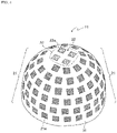
- FIG. 4 is a perspective view showing one example of antenna 11 of communication apparatus 10 of FIG. 3 .
- communication apparatus 10 includes antenna 11, transmission and reception unit 12, and beam forming unit (beam forming circuitry) 13.
- antenna 11 has conformal array antenna 21 and zenith array antenna 22.
- a part outside dotted frame A1 of antenna 11 shown in FIG. 4 indicates conformal array antenna 21.
- a part within dotted frame A1 indicates zenith array antenna 22.
- Conformal array antenna 21 has a plurality of antenna elements 21a.
- Zenith array antenna 22 has a plurality of antenna elements 22a.
- antenna 11 has base 31 having a dome shape.
- antenna 11 has base 31 having a hemispherical shape.
- Base 31 may be provided, for example, on a body surface in a plan view of the aircraft. In other words, base 31 may be provided on the body surface of the upper part of the aircraft. Base 31 may be a part of a body of the aircraft and antenna elements 21a, 22a may be disposed on the body surface of the aircraft.
- Conformal array antenna 21 is configured by arranging the plurality of antenna elements 21a in a region surrounding a region including a zenith of base 31.
- zenith array antenna 22 is configured by arranging the plurality of antenna elements 21a in a region outside dotted frame A1 in FIG. 4 .
- Conformal array antenna 21 may be regarded as an antenna including a plurality of antenna elements 21a arranged on a curved surface.
- Zenith array antenna 22 is configured by arranging a plurality of antenna elements 21a in the region including the zenith of base 31.
- zenith array antenna 22 is configured by arranging the plurality of antenna elements 21a in a region within dotted frame A1 in FIG. 4 .
- Zenith array antenna 22 may have the plurality of antenna elements 22a arranged on a curved surface or the plurality of antenna elements 21a arranged on a flat surface.
- the part within dotted frame A1 of base 31 may be a curved surface (part of a hemispherical surface) or a flat surface.
- Antenna elements 21a of conformal array antenna 21 are spirally arranged on a surface of base 31 having a hemispherical shape.
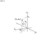
- antenna elements 21a are disposed at a position where a polar coordinate ( ⁇ k , ⁇ k ) of the k-th element is calculated by a generalized spiral series.
- antenna elements 21a are disposed on the curved surface of base 31 in accordance with the following generalized spiral series formula.
- FIG. 5 is a diagram showing an example of a polar coordinate ( ⁇ k , ⁇ k ) of the k-th element of conformal array antenna 21.
- Antenna elements 21a of conformal array antenna 21 are disposed such that element intervals are uniform on the curved surface in accordance with the above generalized spiral series formula.
- Antenna elements 22a of zenith array antenna 22 are disposed in the region including the zenith of antenna 11 (base 31), and are disposed at element intervals equivalent to element intervals of conformal array antenna 21.
- antenna elements 21a of conformal array antenna 21 are disposed in the region surrounding the region including zenith of base 31 having a hemispherical shape. That is, antenna elements 21a of conformal array antenna 21 are disposed over 360 degrees (0° ⁇ ⁇ k ⁇ 360°) around base 31 in a horizontal direction. This allows antenna 11 to emit a beam in any direction around base 31.
- antenna elements 22a of zenith array antenna 22 are disposed in the region including the zenith of base 31 having a hemispherical shape.
- the zenith of base 31 having a hemispherical shape has a better peripheral view than other parts of base 31.
- zenith array antenna 22 of antenna 11 is suitable for forming a broad beam.
- Transmission and reception unit 12 shown in FIG. 3 converts a digital signal output from beam forming unit 13 into an analog high frequency signal.
- Transmission and reception unit 12 amplifies the converted analog high frequency signal to a predetermined power level and outputs the signal to antenna elements 21a, 22a.
- transmission and reception unit 12 converts the digital signal output from beam forming unit 13 into a band-limited analog intermediate frequency (IF) signal with a digital-to-analog converter (DAC).
- Transmission and reception unit 12 converts the analog IF signal into a band-limited signal in a transmission frequency band with an up converter.
- Transmission and reception unit 12 amplifies the power of the frequency-converted signal with a power amplifier (PA).
- PA power amplifier
- Transmission and reception unit 12 outputs the power-amplified signal to antenna elements 21a, 22a via a duplexer (DPX).
- the duplexer is a device for sharing antenna elements 21a, 22a between transmission and reception.
- Transmission and reception unit 12 converts reception signals received by antenna elements 21a, 22a into low noise digital signals.
- transmission and reception unit 12 band-limits the reception signals received by antenna elements 21a, 22a with the duplexer, and then amplifies the signals with a low noise amplifier (LNA).
- LNA low noise amplifier
- Transmission and reception unit 12 frequency-converts the amplified reception signals into band-limited analog IF signals with a down converter.
- Transmission and reception unit 12 converts the analog IF signals into digital signals with an analog-to-digital converter (ADC).
- ADC analog-to-digital converter
- Beam forming unit 13 acquires position information such as coordinates of the aircraft and the satellite from an external network connected via interface 14.
- the position information of the aircraft may be acquired by using, for example, a global positioning system (GPS).
- GPS global positioning system
- the coordinate of the satellite and other information may be acquired in advance from, for example, a service company that provides the position information of the satellite.
- the position information of the aircraft may include an attitude of the aircraft.
- Beam forming unit 13 forms a beam for the satellite to communicate with. For example, beam forming unit 13, using the acquired position information, calculates a weight having a suitable tracking characteristics for the satellite to communicate with. Beam forming unit 13 gives (multiplies) the calculated weight to a transmission signal transmitted to the satellite and a reception signal received from the satellite.
- beam forming unit 13 generates a digital signal by giving a weight w_Txk for the k-th antenna element to a transmission baseband signal Tx. Further, beam forming unit 13 gives a weight w_Rxk to the digital signal of the signal received from the satellite, which is output from transmission and reception unit 12, and synthesizes the digital signal to generate a reception baseband signal Rx.
- Beam forming unit 13 forms a narrow beam using conformal array antenna 21 for a geostationary satellite, for example.
- beam forming unit 13 forms a narrow beam for the geostationary satellite, for example, using conformal array antenna 21 and zenith array antenna 22.
- Beam forming unit 13 forms a broad beam using zenith array antenna 22 for a satellite in the LEO or the like having a high relative speed. For example, beam forming unit 13 forms a beam having a wider beam width than a narrow beam for the geostationary satellite with respect to a satellite that orbits at a relative speed equal to or higher than a predetermined value. The relative speed may be calculated from the positions of the aircraft and satellite.
- Beam forming unit 13 forms a broad beam using zenith array antenna 22 for a satellite having a low altitude, for example.
- beam forming unit 13 forms a broad beam using zenith array antenna 22 for a satellite having a lower altitude than an altitude of the geostationary satellite.
- Beam forming unit 13 may calculate the weight of conformal array antenna 21 that spreads the beam of zenith array antenna 22. For example, beam forming unit 13 may form a broad beam by calculating the weight of conformal array antenna 21 that disperses transmission power of antenna element 22a.
- antenna 11 of communication apparatus 10 has base 31 having a dome shape, antenna elements 22a (first antenna elements) disposed in a first region including the zenith of base 31 (for example, the area within dotted frame A1 in FIG. 4 ), and the plurality of antenna elements 21a (second antenna elements) disposed in a second region surrounding the first region (for example, the region outside dotted frame A1 in FIG. 4 , a region excluding the first region).
- Beam forming unit 13 of communication apparatus 10 calculates a weight based on the position information of the satellite to communicate with, and multiplies the signals transmitted and received by the antenna elements 21a and 22a by the weight.
- the multiplication of the weight also includes setting one of the first antenna elements or the second antenna elements to 0.
- control may be done separately for more regions (regions of N).
- communication apparatus 10 forms a narrow beam corresponding to the position and attitude of the aircraft for the geostationary satellite and a wide beam for the satellite orbiting in the LEO or the like without moving the antenna to appropriately communicate with the satellites.
- communication apparatus 10 can flexibly cope with communication with satellites having different altitudes and relative speeds by controlling beams suitable for satellites to communicate with and adapting to different tracking characteristics for each satellite.
- communication apparatus 10 can flexibly cope with communication with geostationary satellites and communication with satellites in the LEO, MEO, GEO, and the like.
- communication apparatus 10 can simultaneously communicate with a plurality of satellites.
- communication apparatus 10 can simultaneously communicate with a plurality of satellites by using different beams.
- antenna elements 21a of conformal array antenna 21 are disposed in the polar coordinate of the generalized spiral series formula.
- an offset corresponding to, for example, a position where antenna 11 is installed may be added to the polar coordinate.
- Electromagnetic waves transmitted and received by antenna 11 may be either linearly polarized waves or circularly polarized waves. Antenna 11 sharing two orthogonal polarized waves can improve communication performance.
- the number of antenna elements 22a of zenith array antenna 22 is plural, but the number is not limited thereto.
- the number of antenna elements 22a of zenith array antenna 22 may be one.
- Communication apparatus 10 may be paraphrased as an antenna device.
- Base 31 may have a vertically long semi-elliptical shape.
- Base 31 may have a horizontally long semi-elliptical shape. That is, the dome shape of base 31 may include a shape having a zenith and a curved surface such as a hemispherical shape, a vertically long semi-elliptical shape, and a horizontally long semi-elliptical shape.
- the conformal array antenna may have antenna elements on a cylindrical side surface.
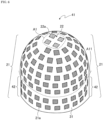
- FIG. 6 is a perspective view showing one example of antenna 41 according to a second exemplary embodiment.
- identical reference numerals designate identical components to components in FIG. 4 .
- a lower part of base 31 has a cylindrical shape.
- base 31 below dotted line A11 in FIG. 6 has a columnar shape. That is, base 31 has a cylindrical shape, and has a hemispherical shape at one end of the cylindrical shape.
- Antenna elements 21a of conformal array antenna 21 are also disposed in the cylindrical part of base 31.
- the cylindrical part of conformal array antenna 21 (part below dotted line A11 in FIG. 6 ) may be referred to as a cylinder array antenna.
- Antenna elements 21a in cylinder array antenna 42 shown in FIG. 6 are disposed so as to be continuous with antenna elements 21a disposed in the hemispherical part of base 31.
- antenna elements 21a on cylinder array antenna 42 are disposed based on the above generalized spiral series formula.
- Antenna elements 21a in cylinder array antenna 42 may be disposed at equal intervals in a cylindrical coordinate system.
- conformal array antenna 21 may partially include cylinder array antenna 42. This also allows communication apparatus 10 to properly communicate with a plurality of satellites.
- communication apparatus 10 compensates a decrease in an opening of antenna 41 even when the geostationary satellite is located in a direction at low elevation angle during a high-altitude travel of the aircraft because antenna 41 has cylinder array antenna 42.
- the antenna elements may be bullseye antenna elements having a concentric antenna structure.
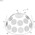
- FIG. 7 is a perspective view showing one example of antenna 51 according to a third exemplary embodiment.
- identical reference numerals designate identical components to components in FIG. 4 .
- conformal array antenna 21 of antenna 51 has a plurality of bullseye antenna elements 52.
- Bullseye antenna elements 52 may be disposed based on the above generalized spiral series formula.
- Zenith array antenna 22 of antenna 51 has bullseye antenna element 53.
- zenith array antenna 22 has one bullseye antenna element 53, but may have a plurality of bullseye antenna elements.
- conformal array antenna 21 may have bullseye antenna elements 52.
- Zenith array antenna 22 may include bullseye antenna element 53. Bullseye antenna elements 52, 53 have higher directivity gain than patch antenna elements, and therefore communication apparatus 10 can form a beam with a smaller number of elements.
- the bullseye antenna element may be applied to antenna 41 having cylinder array antenna 42 described in the second exemplary embodiment.
- the antenna may have soft boundaries.
- FIG. 8 is a perspective view showing one example of antenna 61 according to a fourth exemplary embodiment.
- identical reference numerals designate identical components to components in FIG. 7 .
- antenna 61 has soft boundaries 62.
- Soft boundaries 62 are formed between bullseye antenna elements 52, 53 formed on the surface of base 31.
- Soft boundaries 62 are configured by, for example, a corrugated structure including a plurality of grooves.
- a depth of the grooves of the corrugated structure is, for example, 1/4 of a wavelength of an electromagnetic wave of the transmission signal or the reception signal.
- antenna 61 may have the soft boundaries between bullseye antenna elements 52, 53. This suppresses interference between bullseye antenna elements 52, 53, and communication apparatus 10 can improve accuracy of beam formation.
- Soft boundaries 62 are not limited to the corrugated structure. Soft boundaries 62 may have a structure having a function of adjusting a boundary impedance of antenna 61 with respect to the surface wave, for example. For example, soft boundary 62 may be formed on the surface of base 31 by a structure having a function of adjusting the boundary impedance such as a frequency selective boundary or a metamaterial.
- Soft boundary 62 may be applied to antenna 11 described in the first exemplary embodiment and antenna 41 described in the second exemplary embodiment.
- the notation "unit” used for each component may be replaced with another notation such as “circuit (circuitry)", “device”, “unit”, or “module”.
- the present disclosure can be achieved by software, hardware, or software linked with hardware.
- the functional blocks used for describing the exemplary embodiments are partially or wholly achieved as a large-scale integration (LSI) as an integrated circuit. Each process described in the exemplary embodiments may be partially or wholly controlled by one LSI or a combination of LSIs.
- the LSI may be configured by individual chips, or may be configured by one chip so as to include some or all of the functional blocks.
- the LSI may include data input and output.
- the LSI may be referred to as an IC, a system LSI, a super LSI, or an ultra LSI depending on an integration degree.
- a method of circuit integration is not limited to the LSI, and may be achieved by a dedicated circuit, a general-purpose processor, or a dedicated processor.
- a field programmable gate array (FPGA) that can be programmed after the LSI is manufactured, or a reconfigurable processor that can reconfigure connection and setting of circuit cells inside the LSI may be used.
- FPGA field programmable gate array
- the present disclosure may be implemented as digital processing or analog processing.
- the communication apparatus is not limited to being mounted on an aircraft, but can be applied to any flying body such as an unmanned aerial vehicle or a drone. Further, as long as the communication apparatus communicates with a satellite, the communication apparatus can be applied to a mobile body on the ground.
- the communication apparatus has flexible tracking performance that corresponds to one or both of the altitude and the relative speed of a satellite, and is useful as a communication apparatus that provides, for example, an internet connection service in an aircraft. Further, the communication apparatus of the present disclosure can be applied to communication with a ground earth station.
Landscapes
- Engineering & Computer Science (AREA)
- Computer Networks & Wireless Communication (AREA)
- Signal Processing (AREA)
- Physics & Mathematics (AREA)
- Astronomy & Astrophysics (AREA)
- Aviation & Aerospace Engineering (AREA)
- General Physics & Mathematics (AREA)
- Variable-Direction Aerials And Aerial Arrays (AREA)
- Radio Relay Systems (AREA)
Claims (8)
- Kommunikationsvorrichtung (10), die umfasst:eine Antenne (11, 41, 51, 61), die einen Träger (31) mit einer Kuppelform, ein erstes Antennenelement (22a), das in einem ersten Bereich angeordnet ist, der einen Zenit des Trägers (31) einschließt, und eine Vielzahl zweiter Antennenelemente (21a) enthält, die in einem zweiten Bereich des Trägers (31) angeordnet sind; sowieeine Strahlformungs-Schaltung (13), die in Funktion auf Basis von Positionsinformationen eines Ziel-Satelliten, mit dem kommuniziert werden soll, eine Strahlformung des ersten Antennenelementes (22a) und der Vielzahl zweiter Antennenelemente (21a) steuert,dadurch gekennzeichnet, dassdie Vielzahl zweiter Antennenelemente (21a) auf einer gekrümmten Fläche des Trägers (31) auf Basis einer verallgemeinerten Spiralsequenz angeordnet sind.
- Kommunikationsvorrichtung (10) nach Anspruch 1, wobei die Strahlformungs-Schaltung (13) ein Gewicht auf Basis der Positions-Informationen des Ziel-Satelliten berechnet und ein Signal, das von jedem von dem ersten Antennenelement (22a) und dem einen oder den mehreren zweiten Antennenelement/en (21a) gesendet oder empfangen wird, mit dem Gewicht multipliziert.
- Kommunikationsvorrichtung (10) nach Anspruch 1 oder 2, wobeidie Strahlformungs-Schaltung(13) einen ersten Strahl formt, wenn der Satellit, mit dem kommuniziert werden soll, ein geostationärer Satellit ist, unddie Strahlformungs-Schaltung (13) einen zweiten Strahl formt, der eine Strahlbreite hat, die größer ist als die Strahlbreite des ersten Strahls, wenn der Ziel-Satellit auf einer niedrigeren Umlaufbahn als der Umlaufbahn des geostationären Satelliten umläuft, oder wenn der Ziel-Satellit mit einer relativen Geschwindigkeit umläuft, die höher ist als oder genauso hoch wie ein vorgegebener Wert in Bezug auf die Kommunikationsvorrichtung (10).
- Kommunikationsvorrichtung (10) nach einem der Ansprüche 1 bis 3, wobei jedes von dem ersten Antennenelement (22a) und dem einen oder den mehreren zweiten Antennenelement/en (21a) ein Bullseye-Antennenelement (52, 53) ist.
- Kommunikationsvorrichtung (10) nach einem der Ansprüche 1 bis 4, wobei die Antenne (61) eine weiche Begrenzung (62) aufweist.
- Kommunikationsvorrichtung (10) nach Anspruch 5, wobei die weiche Begrenzung (62) eine gewellte Struktur aufweist.
- Kommunikationsvorrichtung (10) nach Anspruch 6, wobei die weiche Begrenzung (62) von einem Metamaterial gebildet wird.
- Antenne (11, 41, 51, 61), die umfasst:einen Träger (31) mit einer Kuppelform;ein erstes Antennenelement (22a), das in einem ersten Bereich angeordnet ist, der einen Zenit des Trägers (31) einschließt; sowieeine Vielzahl zweiter Antennenelemente (21a), die in einem zweiten Bereich des Trägers (31) angeordnet sind,dadurch gekennzeichnet, dassdie Vielzahl zweiter Antennenelemente (21a) auf einer gekrümmten Fläche des Trägers (31) auf Basis einer verallgemeinerten Spiralsequenz angeordnet sind.
Applications Claiming Priority (2)
| Application Number | Priority Date | Filing Date | Title |
|---|---|---|---|
| US201962880393P | 2019-07-30 | 2019-07-30 | |
| JP2020072291A JP7486086B2 (ja) | 2019-07-30 | 2020-04-14 | 通信装置およびアンテナ |
Publications (2)
| Publication Number | Publication Date |
|---|---|
| EP3772190A1 EP3772190A1 (de) | 2021-02-03 |
| EP3772190B1 true EP3772190B1 (de) | 2023-03-08 |
Family
ID=71661722
Family Applications (1)
| Application Number | Title | Priority Date | Filing Date |
|---|---|---|---|
| EP20186215.8A Active EP3772190B1 (de) | 2019-07-30 | 2020-07-16 | Kommunikationsvorrichtung und antenne |
Country Status (2)
| Country | Link |
|---|---|
| US (1) | US11646505B2 (de) |
| EP (1) | EP3772190B1 (de) |
Families Citing this family (1)
| Publication number | Priority date | Publication date | Assignee | Title |
|---|---|---|---|---|
| WO2021240214A1 (en) * | 2020-05-26 | 2021-12-02 | Telefonaktiebolaget Lm Ericsson (Publ) | Antenna solution for mm-wave systems |
Family Cites Families (32)
| Publication number | Priority date | Publication date | Assignee | Title |
|---|---|---|---|---|
| US3034121A (en) * | 1959-12-23 | 1962-05-08 | Henry B Riblet | Broad band spherical antenna |
| US4792808A (en) * | 1982-12-14 | 1988-12-20 | Harris Corp. | Ellipsoid distribution of antenna array elements for obtaining hemispheric coverage |
| EP0611490B1 (de) * | 1991-11-08 | 1998-10-07 | Teledesic LLC | Bodenantennen für satellitenkommunikationssystem |
| US5451973A (en) * | 1993-11-02 | 1995-09-19 | Trw Inc. | Multi-mode dual circularly polarized spiral antenna |
| US6011524A (en) * | 1994-05-24 | 2000-01-04 | Trimble Navigation Limited | Integrated antenna system |
| EP0710055B1 (de) * | 1994-10-31 | 1999-06-23 | Applied Materials, Inc. | Plasmareaktoren zur Halbleiterscheibenbehandlung |
| US5919382A (en) * | 1994-10-31 | 1999-07-06 | Applied Materials, Inc. | Automatic frequency tuning of an RF power source of an inductively coupled plasma reactor |
| US5838284A (en) * | 1996-05-17 | 1998-11-17 | The Boeing Company | Spiral-shaped array for broadband imaging |
| US6373022B2 (en) * | 1997-06-30 | 2002-04-16 | Applied Materials, Inc. | Plasma reactor with antenna of coil conductors of concentric helices offset along the axis of symmetry |
| US6292134B1 (en) * | 1999-02-26 | 2001-09-18 | Probir K. Bondyopadhyay | Geodesic sphere phased array antenna system |
| US6401652B1 (en) * | 2000-05-04 | 2002-06-11 | Applied Materials, Inc. | Plasma reactor inductive coil antenna with flat surface facing the plasma |
| SE517649C2 (sv) * | 2000-11-06 | 2002-07-02 | Ericsson Telefon Ab L M | Gruppantenn med smala huvudlober i horisontalplanet |
| JP3767372B2 (ja) | 2000-11-22 | 2006-04-19 | 三菱電機株式会社 | 衛星追尾用アンテナ制御装置 |
| US6842157B2 (en) * | 2001-07-23 | 2005-01-11 | Harris Corporation | Antenna arrays formed of spiral sub-array lattices |
| US6646621B1 (en) * | 2002-04-25 | 2003-11-11 | Harris Corporation | Spiral wound, series fed, array antenna |
| US6961025B1 (en) * | 2003-08-18 | 2005-11-01 | Lockheed Martin Corporation | High-gain conformal array antenna |
| JP2005236393A (ja) * | 2004-02-17 | 2005-09-02 | Alps Electric Co Ltd | 異周波共用アンテナ |
| DE102004058862A1 (de) * | 2004-12-06 | 2006-06-14 | Endress + Hauser Gmbh + Co. Kg | Vorrichtung zum Aussenden und/oder Empfangen von Hochfrequenzsignalen in ein offenes oder ein geschlossenes Raumsystem |
| TWI381585B (zh) * | 2009-06-30 | 2013-01-01 | Wistron Neweb Corp | 雙頻天線裝置 |
| US8745853B2 (en) * | 2010-07-05 | 2014-06-10 | Universal Display Corporation | Antenna fabrication with three-dimensional contoured substrates |
| US8594735B2 (en) * | 2011-01-05 | 2013-11-26 | Alcatel Lucent | Conformal antenna array |
| US9000982B2 (en) * | 2012-03-09 | 2015-04-07 | Lockheed Martin Corporation | Conformal array antenna |
| WO2014099079A1 (en) * | 2012-09-27 | 2014-06-26 | Raytheon Company | Methods and apparatus for fragmented phased array radar |
| CA3013982A1 (en) * | 2016-02-12 | 2017-08-17 | Aeronet Global Communications Labs Dac | Antenna array for aeronautical communications |
| US10847879B2 (en) * | 2016-03-11 | 2020-11-24 | Huawei Technologies Canada Co., Ltd. | Antenna array structures for half-duplex and full-duplex multiple-input and multiple-output systems |
| US11245185B2 (en) * | 2016-06-14 | 2022-02-08 | Miles Space, Inc. | Portable phased aperture array antenna |
| US10454180B2 (en) * | 2016-12-14 | 2019-10-22 | Raytheon Company | Isolation barrier |
| JP2018121127A (ja) * | 2017-01-23 | 2018-08-02 | 株式会社東芝 | 無線装置 |
| US11050152B2 (en) * | 2018-02-09 | 2021-06-29 | Avx Corporation | AESA compound curred dome phased array antenna |
| GB201803922D0 (en) * | 2018-03-12 | 2018-04-25 | Ttp Plc | Phased antenna array device |
| US11133604B1 (en) * | 2018-05-07 | 2021-09-28 | Rockwell Collins, Inc. | Circularly symmetric tightly coupled dipole array |
| US10903567B2 (en) * | 2018-06-04 | 2021-01-26 | Infineon Technologies Ag | Calibrating a phased array system |
-
2020
- 2020-07-16 EP EP20186215.8A patent/EP3772190B1/de active Active
- 2020-07-28 US US16/940,969 patent/US11646505B2/en active Active
Also Published As
| Publication number | Publication date |
|---|---|
| US11646505B2 (en) | 2023-05-09 |
| US20210036435A1 (en) | 2021-02-04 |
| EP3772190A1 (de) | 2021-02-03 |
Similar Documents
| Publication | Publication Date | Title |
|---|---|---|
| US11956066B2 (en) | System and method for high throughput fractionated satellites (HTFS) for direct connectivity to and from end user devices and terminals using flight formations of small or very small satellites | |
| US10903565B2 (en) | Architectures and methods for novel antenna radiation optimization via feed repositioning | |
| US11870540B2 (en) | System and method for high throughput fractionated satellites (HTFS) for direct connectivity to and from end user devices and terminals using flight formations of small or very small satellites | |
| US7250905B2 (en) | Virtual antenna technology (VAT) and applications | |
| US12542355B2 (en) | System and method for a digitally beamformed phased array feed | |
| US20140327577A1 (en) | Low cost high performance aircraft antenna for advanced ground to air internet system | |
| EP4236085A2 (de) | Fraktionierte satelliten mit hohem durchsatz | |
| US12283758B2 (en) | System and methods for use with electronically steerable antennas for wireless communications | |
| EP3240204B1 (de) | System und verfahren zur aufrechterhaltung der kommunikation über einem abdeckungsgebiet | |
| EP3772190B1 (de) | Kommunikationsvorrichtung und antenne | |
| JP7486086B2 (ja) | 通信装置およびアンテナ | |
| US20230370153A1 (en) | Multi-beam multi-band protected communication system | |
| CN111740771A (zh) | 一种混合多波束形成方法及相关装置 | |
| DiCarlofelice et al. | Phased Antenna Array Concept for Flexible Satellite Communications in Ka-Band |
Legal Events
| Date | Code | Title | Description |
|---|---|---|---|
| PUAI | Public reference made under article 153(3) epc to a published international application that has entered the european phase |
Free format text: ORIGINAL CODE: 0009012 |
|
| STAA | Information on the status of an ep patent application or granted ep patent |
Free format text: STATUS: THE APPLICATION HAS BEEN PUBLISHED |
|
| AK | Designated contracting states |
Kind code of ref document: A1 Designated state(s): AL AT BE BG CH CY CZ DE DK EE ES FI FR GB GR HR HU IE IS IT LI LT LU LV MC MK MT NL NO PL PT RO RS SE SI SK SM TR |
|
| AX | Request for extension of the european patent |
Extension state: BA ME |
|
| STAA | Information on the status of an ep patent application or granted ep patent |
Free format text: STATUS: REQUEST FOR EXAMINATION WAS MADE |
|
| 17P | Request for examination filed |
Effective date: 20210727 |
|
| RBV | Designated contracting states (corrected) |
Designated state(s): AL AT BE BG CH CY CZ DE DK EE ES FI FR GB GR HR HU IE IS IT LI LT LU LV MC MK MT NL NO PL PT RO RS SE SI SK SM TR |
|
| RIC1 | Information provided on ipc code assigned before grant |
Ipc: H04B 7/204 20060101ALI20220906BHEP Ipc: H04B 7/185 20060101AFI20220906BHEP |
|
| GRAP | Despatch of communication of intention to grant a patent |
Free format text: ORIGINAL CODE: EPIDOSNIGR1 |
|
| STAA | Information on the status of an ep patent application or granted ep patent |
Free format text: STATUS: GRANT OF PATENT IS INTENDED |
|
| INTG | Intention to grant announced |
Effective date: 20221017 |
|
| GRAS | Grant fee paid |
Free format text: ORIGINAL CODE: EPIDOSNIGR3 |
|
| GRAA | (expected) grant |
Free format text: ORIGINAL CODE: 0009210 |
|
| STAA | Information on the status of an ep patent application or granted ep patent |
Free format text: STATUS: THE PATENT HAS BEEN GRANTED |
|
| AK | Designated contracting states |
Kind code of ref document: B1 Designated state(s): AL AT BE BG CH CY CZ DE DK EE ES FI FR GB GR HR HU IE IS IT LI LT LU LV MC MK MT NL NO PL PT RO RS SE SI SK SM TR |
|
| REG | Reference to a national code |
Ref country code: CH Ref legal event code: EP Ref country code: AT Ref legal event code: REF Ref document number: 1553294 Country of ref document: AT Kind code of ref document: T Effective date: 20230315 |
|
| REG | Reference to a national code |
Ref country code: IE Ref legal event code: FG4D |
|
| REG | Reference to a national code |
Ref country code: DE Ref legal event code: R096 Ref document number: 602020008659 Country of ref document: DE |
|
| REG | Reference to a national code |
Ref country code: LT Ref legal event code: MG9D |
|
| REG | Reference to a national code |
Ref country code: NL Ref legal event code: MP Effective date: 20230308 |
|
| PG25 | Lapsed in a contracting state [announced via postgrant information from national office to epo] |
Ref country code: RS Free format text: LAPSE BECAUSE OF FAILURE TO SUBMIT A TRANSLATION OF THE DESCRIPTION OR TO PAY THE FEE WITHIN THE PRESCRIBED TIME-LIMIT Effective date: 20230308 Ref country code: NO Free format text: LAPSE BECAUSE OF FAILURE TO SUBMIT A TRANSLATION OF THE DESCRIPTION OR TO PAY THE FEE WITHIN THE PRESCRIBED TIME-LIMIT Effective date: 20230608 Ref country code: LV Free format text: LAPSE BECAUSE OF FAILURE TO SUBMIT A TRANSLATION OF THE DESCRIPTION OR TO PAY THE FEE WITHIN THE PRESCRIBED TIME-LIMIT Effective date: 20230308 Ref country code: LT Free format text: LAPSE BECAUSE OF FAILURE TO SUBMIT A TRANSLATION OF THE DESCRIPTION OR TO PAY THE FEE WITHIN THE PRESCRIBED TIME-LIMIT Effective date: 20230308 Ref country code: HR Free format text: LAPSE BECAUSE OF FAILURE TO SUBMIT A TRANSLATION OF THE DESCRIPTION OR TO PAY THE FEE WITHIN THE PRESCRIBED TIME-LIMIT Effective date: 20230308 Ref country code: ES Free format text: LAPSE BECAUSE OF FAILURE TO SUBMIT A TRANSLATION OF THE DESCRIPTION OR TO PAY THE FEE WITHIN THE PRESCRIBED TIME-LIMIT Effective date: 20230308 |
|
| REG | Reference to a national code |
Ref country code: AT Ref legal event code: MK05 Ref document number: 1553294 Country of ref document: AT Kind code of ref document: T Effective date: 20230308 |
|
| PG25 | Lapsed in a contracting state [announced via postgrant information from national office to epo] |
Ref country code: SE Free format text: LAPSE BECAUSE OF FAILURE TO SUBMIT A TRANSLATION OF THE DESCRIPTION OR TO PAY THE FEE WITHIN THE PRESCRIBED TIME-LIMIT Effective date: 20230308 Ref country code: NL Free format text: LAPSE BECAUSE OF FAILURE TO SUBMIT A TRANSLATION OF THE DESCRIPTION OR TO PAY THE FEE WITHIN THE PRESCRIBED TIME-LIMIT Effective date: 20230308 Ref country code: GR Free format text: LAPSE BECAUSE OF FAILURE TO SUBMIT A TRANSLATION OF THE DESCRIPTION OR TO PAY THE FEE WITHIN THE PRESCRIBED TIME-LIMIT Effective date: 20230609 Ref country code: FI Free format text: LAPSE BECAUSE OF FAILURE TO SUBMIT A TRANSLATION OF THE DESCRIPTION OR TO PAY THE FEE WITHIN THE PRESCRIBED TIME-LIMIT Effective date: 20230308 |
|
| PG25 | Lapsed in a contracting state [announced via postgrant information from national office to epo] |
Ref country code: SM Free format text: LAPSE BECAUSE OF FAILURE TO SUBMIT A TRANSLATION OF THE DESCRIPTION OR TO PAY THE FEE WITHIN THE PRESCRIBED TIME-LIMIT Effective date: 20230308 Ref country code: RO Free format text: LAPSE BECAUSE OF FAILURE TO SUBMIT A TRANSLATION OF THE DESCRIPTION OR TO PAY THE FEE WITHIN THE PRESCRIBED TIME-LIMIT Effective date: 20230308 Ref country code: PT Free format text: LAPSE BECAUSE OF FAILURE TO SUBMIT A TRANSLATION OF THE DESCRIPTION OR TO PAY THE FEE WITHIN THE PRESCRIBED TIME-LIMIT Effective date: 20230710 Ref country code: EE Free format text: LAPSE BECAUSE OF FAILURE TO SUBMIT A TRANSLATION OF THE DESCRIPTION OR TO PAY THE FEE WITHIN THE PRESCRIBED TIME-LIMIT Effective date: 20230308 Ref country code: CZ Free format text: LAPSE BECAUSE OF FAILURE TO SUBMIT A TRANSLATION OF THE DESCRIPTION OR TO PAY THE FEE WITHIN THE PRESCRIBED TIME-LIMIT Effective date: 20230308 Ref country code: AT Free format text: LAPSE BECAUSE OF FAILURE TO SUBMIT A TRANSLATION OF THE DESCRIPTION OR TO PAY THE FEE WITHIN THE PRESCRIBED TIME-LIMIT Effective date: 20230308 |
|
| PG25 | Lapsed in a contracting state [announced via postgrant information from national office to epo] |
Ref country code: SK Free format text: LAPSE BECAUSE OF FAILURE TO SUBMIT A TRANSLATION OF THE DESCRIPTION OR TO PAY THE FEE WITHIN THE PRESCRIBED TIME-LIMIT Effective date: 20230308 Ref country code: PL Free format text: LAPSE BECAUSE OF FAILURE TO SUBMIT A TRANSLATION OF THE DESCRIPTION OR TO PAY THE FEE WITHIN THE PRESCRIBED TIME-LIMIT Effective date: 20230308 Ref country code: IS Free format text: LAPSE BECAUSE OF FAILURE TO SUBMIT A TRANSLATION OF THE DESCRIPTION OR TO PAY THE FEE WITHIN THE PRESCRIBED TIME-LIMIT Effective date: 20230708 |
|
| REG | Reference to a national code |
Ref country code: DE Ref legal event code: R097 Ref document number: 602020008659 Country of ref document: DE |
|
| PLBE | No opposition filed within time limit |
Free format text: ORIGINAL CODE: 0009261 |
|
| STAA | Information on the status of an ep patent application or granted ep patent |
Free format text: STATUS: NO OPPOSITION FILED WITHIN TIME LIMIT |
|
| PG25 | Lapsed in a contracting state [announced via postgrant information from national office to epo] |
Ref country code: SI Free format text: LAPSE BECAUSE OF FAILURE TO SUBMIT A TRANSLATION OF THE DESCRIPTION OR TO PAY THE FEE WITHIN THE PRESCRIBED TIME-LIMIT Effective date: 20230308 Ref country code: DK Free format text: LAPSE BECAUSE OF FAILURE TO SUBMIT A TRANSLATION OF THE DESCRIPTION OR TO PAY THE FEE WITHIN THE PRESCRIBED TIME-LIMIT Effective date: 20230308 |
|
| 26N | No opposition filed |
Effective date: 20231211 |
|
| PG25 | Lapsed in a contracting state [announced via postgrant information from national office to epo] |
Ref country code: MC Free format text: LAPSE BECAUSE OF FAILURE TO SUBMIT A TRANSLATION OF THE DESCRIPTION OR TO PAY THE FEE WITHIN THE PRESCRIBED TIME-LIMIT Effective date: 20230308 |
|
| PG25 | Lapsed in a contracting state [announced via postgrant information from national office to epo] |
Ref country code: MC Free format text: LAPSE BECAUSE OF FAILURE TO SUBMIT A TRANSLATION OF THE DESCRIPTION OR TO PAY THE FEE WITHIN THE PRESCRIBED TIME-LIMIT Effective date: 20230308 |
|
| REG | Reference to a national code |
Ref country code: CH Ref legal event code: PL |
|
| REG | Reference to a national code |
Ref country code: BE Ref legal event code: MM Effective date: 20230731 |
|
| PG25 | Lapsed in a contracting state [announced via postgrant information from national office to epo] |
Ref country code: LU Free format text: LAPSE BECAUSE OF NON-PAYMENT OF DUE FEES Effective date: 20230716 |
|
| PG25 | Lapsed in a contracting state [announced via postgrant information from national office to epo] |
Ref country code: LU Free format text: LAPSE BECAUSE OF NON-PAYMENT OF DUE FEES Effective date: 20230716 |
|
| REG | Reference to a national code |
Ref country code: IE Ref legal event code: MM4A |
|
| PG25 | Lapsed in a contracting state [announced via postgrant information from national office to epo] |
Ref country code: CH Free format text: LAPSE BECAUSE OF NON-PAYMENT OF DUE FEES Effective date: 20230731 |
|
| PG25 | Lapsed in a contracting state [announced via postgrant information from national office to epo] |
Ref country code: IT Free format text: LAPSE BECAUSE OF FAILURE TO SUBMIT A TRANSLATION OF THE DESCRIPTION OR TO PAY THE FEE WITHIN THE PRESCRIBED TIME-LIMIT Effective date: 20230308 Ref country code: FR Free format text: LAPSE BECAUSE OF NON-PAYMENT OF DUE FEES Effective date: 20230731 Ref country code: BE Free format text: LAPSE BECAUSE OF NON-PAYMENT OF DUE FEES Effective date: 20230731 |
|
| PG25 | Lapsed in a contracting state [announced via postgrant information from national office to epo] |
Ref country code: IE Free format text: LAPSE BECAUSE OF NON-PAYMENT OF DUE FEES Effective date: 20230716 |
|
| PG25 | Lapsed in a contracting state [announced via postgrant information from national office to epo] |
Ref country code: IE Free format text: LAPSE BECAUSE OF NON-PAYMENT OF DUE FEES Effective date: 20230716 |
|
| PGFP | Annual fee paid to national office [announced via postgrant information from national office to epo] |
Ref country code: DE Payment date: 20240719 Year of fee payment: 5 |
|
| PG25 | Lapsed in a contracting state [announced via postgrant information from national office to epo] |
Ref country code: BG Free format text: LAPSE BECAUSE OF FAILURE TO SUBMIT A TRANSLATION OF THE DESCRIPTION OR TO PAY THE FEE WITHIN THE PRESCRIBED TIME-LIMIT Effective date: 20230308 |
|
| PG25 | Lapsed in a contracting state [announced via postgrant information from national office to epo] |
Ref country code: BG Free format text: LAPSE BECAUSE OF FAILURE TO SUBMIT A TRANSLATION OF THE DESCRIPTION OR TO PAY THE FEE WITHIN THE PRESCRIBED TIME-LIMIT Effective date: 20230308 |
|
| GBPC | Gb: european patent ceased through non-payment of renewal fee |
Effective date: 20240716 |
|
| PG25 | Lapsed in a contracting state [announced via postgrant information from national office to epo] |
Ref country code: GB Free format text: LAPSE BECAUSE OF NON-PAYMENT OF DUE FEES Effective date: 20240716 |
|
| PG25 | Lapsed in a contracting state [announced via postgrant information from national office to epo] |
Ref country code: CY Free format text: LAPSE BECAUSE OF FAILURE TO SUBMIT A TRANSLATION OF THE DESCRIPTION OR TO PAY THE FEE WITHIN THE PRESCRIBED TIME-LIMIT; INVALID AB INITIO Effective date: 20200716 |
|
| PG25 | Lapsed in a contracting state [announced via postgrant information from national office to epo] |
Ref country code: HU Free format text: LAPSE BECAUSE OF FAILURE TO SUBMIT A TRANSLATION OF THE DESCRIPTION OR TO PAY THE FEE WITHIN THE PRESCRIBED TIME-LIMIT; INVALID AB INITIO Effective date: 20200716 |
|
| PG25 | Lapsed in a contracting state [announced via postgrant information from national office to epo] |
Ref country code: TR Free format text: LAPSE BECAUSE OF FAILURE TO SUBMIT A TRANSLATION OF THE DESCRIPTION OR TO PAY THE FEE WITHIN THE PRESCRIBED TIME-LIMIT Effective date: 20230308 |
|
| REG | Reference to a national code |
Ref country code: DE Ref legal event code: R119 Ref document number: 602020008659 Country of ref document: DE |
|
| PG25 | Lapsed in a contracting state [announced via postgrant information from national office to epo] |
Ref country code: DE Free format text: LAPSE BECAUSE OF NON-PAYMENT OF DUE FEES Effective date: 20260203 |