EP3772242B1 - Glissiere et son support - Google Patents
Glissiere et son support Download PDFInfo
- Publication number
- EP3772242B1 EP3772242B1 EP19207857.4A EP19207857A EP3772242B1 EP 3772242 B1 EP3772242 B1 EP 3772242B1 EP 19207857 A EP19207857 A EP 19207857A EP 3772242 B1 EP3772242 B1 EP 3772242B1
- Authority
- EP
- European Patent Office
- Prior art keywords
- rail
- wall
- section
- bracket
- supporting
- Prior art date
- Legal status (The legal status is an assumption and is not a legal conclusion. Google has not performed a legal analysis and makes no representation as to the accuracy of the status listed.)
- Active
Links
Images



Classifications
-
- H—ELECTRICITY
- H05—ELECTRIC TECHNIQUES NOT OTHERWISE PROVIDED FOR
- H05K—PRINTED CIRCUITS; CASINGS OR CONSTRUCTIONAL DETAILS OF ELECTRIC APPARATUS; MANUFACTURE OF ASSEMBLAGES OF ELECTRICAL COMPONENTS
- H05K7/00—Constructional details common to different types of electric apparatus
- H05K7/14—Mounting supporting structure in casing or on frame or rack
- H05K7/1485—Servers; Data center rooms, e.g. 19-inch computer racks
- H05K7/1488—Cabinets therefor, e.g. chassis or racks or mechanical interfaces between blades and support structures
- H05K7/1489—Cabinets therefor, e.g. chassis or racks or mechanical interfaces between blades and support structures characterized by the mounting of blades therein, e.g. brackets, rails, trays
-
- A—HUMAN NECESSITIES
- A47—FURNITURE; DOMESTIC ARTICLES OR APPLIANCES; COFFEE MILLS; SPICE MILLS; SUCTION CLEANERS IN GENERAL
- A47B—TABLES; DESKS; OFFICE FURNITURE; CABINETS; DRAWERS; GENERAL DETAILS OF FURNITURE
- A47B88/00—Drawers for tables, cabinets or like furniture; Guides for drawers
- A47B88/40—Sliding drawers; Slides or guides therefor
- A47B88/423—Fastening devices for slides or guides
- A47B88/427—Fastening devices for slides or guides at drawer side
-
- A—HUMAN NECESSITIES
- A47—FURNITURE; DOMESTIC ARTICLES OR APPLIANCES; COFFEE MILLS; SPICE MILLS; SUCTION CLEANERS IN GENERAL
- A47B—TABLES; DESKS; OFFICE FURNITURE; CABINETS; DRAWERS; GENERAL DETAILS OF FURNITURE
- A47B88/00—Drawers for tables, cabinets or like furniture; Guides for drawers
- A47B88/40—Sliding drawers; Slides or guides therefor
- A47B88/423—Fastening devices for slides or guides
- A47B88/43—Fastening devices for slides or guides at cabinet side
-
- A—HUMAN NECESSITIES
- A47—FURNITURE; DOMESTIC ARTICLES OR APPLIANCES; COFFEE MILLS; SPICE MILLS; SUCTION CLEANERS IN GENERAL
- A47B—TABLES; DESKS; OFFICE FURNITURE; CABINETS; DRAWERS; GENERAL DETAILS OF FURNITURE
- A47B88/00—Drawers for tables, cabinets or like furniture; Guides for drawers
- A47B88/40—Sliding drawers; Slides or guides therefor
- A47B88/49—Sliding drawers; Slides or guides therefor with double extensible guides or parts
-
- A—HUMAN NECESSITIES
- A47—FURNITURE; DOMESTIC ARTICLES OR APPLIANCES; COFFEE MILLS; SPICE MILLS; SUCTION CLEANERS IN GENERAL
- A47B—TABLES; DESKS; OFFICE FURNITURE; CABINETS; DRAWERS; GENERAL DETAILS OF FURNITURE
- A47B88/00—Drawers for tables, cabinets or like furniture; Guides for drawers
- A47B88/40—Sliding drawers; Slides or guides therefor
- A47B88/423—Fastening devices for slides or guides
Definitions
- the present invention is related to a slide rail assembly with improved structural strength and improved structural reliability.
- China patent with publication Number CN 101803832A discloses a slide rail applicable to a server rack.
- the slide rail includes a first rail, a second rail and a third rail.
- the patent does not disclose a bracket able to improve structural reliability of the slide rail assembly.
- a top portion and a bottom portion of the third rail of the patent are U-shaped folded (folded and piled structure) .
- a transverse width of a concave structure of the second rail has to be arranged greater than a transverse width of a passage of the first rail. Therefore, the U-shaped folded portions of the third rail are not able to correspond to a range of the transverse width of the passage of the first rail.
- an overall transverse width of the slide rail assembly is increased, which is a disadvantage for mounting a wide width server on the slide rail assembly.
- Document D1 US 2017/303426 A1 (CHEN YUNG-LIANG [TW]) 19 October 2017 (2017-10-19) disclose a slide rail assembly having a bracket with a supporting portion to support the rail. However, the bracket of document D1 does not disclose the supporting portion of the bracket cover a lateral side of the rail to improve the structure reliability.
- Document D2 US 9,328,769 B1 (CHEN KEN-CHING [TW] ET AL) 3 May 2016 (2016-05-03) disclose a slide rail assembly having a reduced overall width of the rail members. However, the bracket of document D2 does not disclose an extra supporting portion, and the rail members are wrapped by the bracket, such that the overall width of the slide rail assembly is becoming thicker.
- the present invention aims at providing a slide rail assembly with improved structural strength.
- the claimed slide rail assembly includes a first rail, a first bracket, a second bracket and a second rail.
- the first bracket is arranged adjacent to a first end portion of the first rail.
- the first bracket includes a side wall and at least one mounting member adjacent to the side wall.
- the second bracket is arranged adjacent to a second end portion of the first rail.
- the second bracket includes a side plate and at least one second mounting member adjacent to the side plate.
- the second rail is movable relative to the first rail.
- the second rail includes a first wall, a second wall and a longitudinal wall connected between the first wall and the second wall of the second rail.
- a first supporting portion is arranged on the first bracket.
- the first supporting portion includes two first supporting sections.
- one of the two first supporting sections is configured to support the first wall of the second rail in a transverse direction and another one of the two first supporting sections is configured to support the first wall of the second rail in a height direction.
- the first wall of the second rail is located between the first supporting section and the side wall of the first bracket, to prevent the second rail from being moved in the transverse direction.
- the transverse direction and the height direction are substantially perpendicular relative to each other.
- a second supporting portion is arranged on the first bracket.
- the second supporting portion includes two second supporting sections.
- one of the two second supporting sections is configured to support the second wall of the second rail in a transverse direction and another one of the two second supporting sections is configured to support the second wall of the second rail in a height direction.
- the second wall of the second rail is located between the second supporting section and the side wall of the first bracket, to prevent the second rail from being moved in the transverse direction.
- the first wall of the second rail is located between the first supporting section and the side wall of the first bracket and the second wall of the second rail is located between the second supporting section and the side wall of the first bracket, such that the first supporting portion and the first wall of the second rail support each other, the first supporting section supports a lateral side of the first wall of the second rail, the second supporting portion and the second wall of the second rail support each other, and the second supporting section supports a lateral side of the second wall of the second rail.
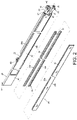
- a slide rail assembly 20 includes a first rail 22, a first bracket 24 and a second rail 26.
- the slide rail assembly 20 further includes a third rail 28 and a second bracket 29.
- the first rail 22 includes a first wall 30a, a second wall 30b and a longitudinal wall 32 connected between the first wall 30a and the second wall 30b of the first rail 22.
- a first passage 33 is defined by the first wall 30a, the second wall 30b and the longitudinal wall 32 of the first rail 22.
- the second rail 26 is movably mounted in the first passage 33.
- the first rail 22 has a first end portion E1 and a second end portion E2 far from the first end portion E1 of the first rail 22.
- the first end portion E1 and the second end portion E2 are respectively a front end portion and a rear end portion of the first rail 22, but the present invention is not limited thereto.
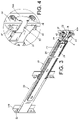
- the first bracket 24 is arranged on the first rail 22.
- the first bracket 24 is located adjacent to the first end portion E1 of the first rail 22.
- the second rail 26 is movable longitudinally relative to the first rail 22.
- the second rail 26 includes a first wall 34a, a second wall 34b and a longitudinal wall 36 connected between the first wall 34a and the second wall 34b of the second rail 26.
- a second passage 37 is defined by the first wall 34a, the second wall 34b and the longitudinal wall 36 of the second rail 26.
- the third rail 28 is movably mounted in the second passage 37.
- the third rail 28 is movable longitudinally relative to the second rail 26.
- the third rail 28 includes a first wall 38a, a second wall 38b and a longitudinal wall 40 connected between the first wall 38a and the second wall 38b of the third rail 28.
- the second bracket 29 is arranged adjacent to the second end portion E2 of the first rail 22.
- a first supporting portion 42 and a second supporting portion 44 are arranged on one of the first rail 22 and the first bracket 24.
- the first supporting portion 42 and the second supporting portion 44 are both arranged on the first bracket 24, and the first supporting portion 42 and the second supporting portion 44 are integrated on the first bracket 24, but the present invention is not limited thereto.
- the first bracket 24 includes a side wall 46 and at least one first mounting member 48 adjacent to the side wall 46.
- the second bracket 29 includes a side plate 50 and at least one second mounting member 52 adjacent to the side plate 50.
- the at least one first mounting member 48 of the first bracket 24 is configured to mount the first rail 22 to a first post 54a of a rack (or a cabinet body).
- the at least one second mounting member 52 of the second bracket 29 is configured to mount the first rail 22 to a second post 54b.
- a fastening member 55 is movably mounted on the first bracket 24, and configured to fasten the first post 54a.
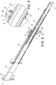
- the first supporting portion 42 and the first wall 34a of the second rail 26 do not support each other, and the second supporting portion 44 and the second wall 34b of the second rail 26 do not support each other.
- At least one of the first wall 30a and the second wall 30b of the first rail 22 includes a first wall section X1 and a second wall section X2 bent relative to the first wall section X1.
- both of the first wall 30a and the second wall 30b of the first rail 22 include the first wall section X1 and the second wall section X2.
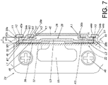
- a transverse width T is form between each one of the second wall sections X2 of the first rail 22 and the longitudinal wall 32 of the first rail 22 (as shown in FIG. 7 ).
- At least one of the first wall 38a and the second wall 38b of the third rail 28 includes a first wall section K1 laterally bent relative to the longitudinal wall 40 of the third rail 28 and a second wall section K2 substantially perpendicularly connected to the first wall section K1 of the third rail 28.
- both of the first wall 38a and the second wall 38b of the third rail 28 include the first wall section K1 and a second wall section K2.
- each one of the second wall sections K2 of the third rail 28 extends into the second passage 37 of the second rail 26, and each one of the second wall sections K2 of the third rail 28 is located correspondingly within the transverse width T of the first rail 22 (such as being located between each one of the second wall sections X2 and the longitudinal wall 32 of the first rail 22) .
- the longitudinal wall 40 of the third rail 28 is located on a plane H, and the plane H is slightly protruded relative to each one of the second wall sections X2 of the first rail 22 by a short distance. Therefore, the longitudinal wall 40 of the third rail 28 and each one of the second wall sections X2 of the first rail 22 can be regarded as on the same plane H substantially. According to above structural features, an overall width of the slide rail assembly is able to be reduced, such that the slide rail assembly can be narrower.
- At least one of the first wall 34a and the second wall 34b of the second rail 26 includes a first extension section M1 laterally bent relative to the longitudinal wall 36 of the second rail 26, a first bending section B1 bently connected to the first extension section M1, a second extension section M2 laterally bent relative to the first bending section B1 and a second bending section B2 bently connected to the second extension section M2.
- both of the first wall 34a and the second wall 34b of the second rail 26 includes the first extension section M1, the first bending section B1, the second extension section M2 and the second bending section B2 .
- structures of the first extension section M1, the first bending section B1, the second extension section M2 and the second bending section B2 are continually bent.
- the structural strength of the second rail 26 is improved, in order to further improve the overall structural strength of the slide rail assembly.
- the second bending section B2 of the second rail 26 and the first wall section K1 of the third rail 28 are able to support each other, to further improve the structural strength of the second rail 26 and the third rail 28.
- an end portion of the second wall section K2 of the third rail 28 is adjacent to the second extension section M2 of the second rail 26.
- the longitudinal wall 36 of the second rail 26 includes a first longitudinal section L1, a second longitudinal section L2 and an intermediate section L3.
- the first longitudinal section L1 and the second longitudinal section L2 are respectively bent from two opposite ends of the intermediate section L3, such that structural strength of the connection of the two opposite ends of the intermediate section L3 and the first longitudinal section L1 and the second longitudinal section L2 is also improved.
- the first supporting portion 42 includes a first supporting section 42a configured to support the first wall 34a of the second rail 26.
- the first supporting section 42a is configured to support the first wall 34a of the second rail 26 in a transverse direction (in other words, the first supporting section 42a supports a lateral side of the first wall 34a of the second rail 26).
- the first wall 34a of the second rail 26 is located between the first supporting section 42a and the side wall 46 of the first bracket 24, to prevent the second rail 26 from being moved in the transverse direction (such as to prevent the second rail 26 from being moved to left or to right in FIG. 7 , but the present invention is specifically not limited thereto) .
- the first supporting portion 42 further includes another first supporting section 42b configured to support the first wall 34a of the second rail 26 in a height direction (such as to prevent an upper portion of the second rail 26 from being moved).
- the transverse direction and the height direction are substantially perpendicular relative to each other.
- the second supporting portion 44 includes a second supporting section 44a configured to support the second wall 34b of the second rail 26.
- the second supporting section 44a is configured to support the second wall 34b of the second rail 26 in the transverse direction (in other words, the second supporting section 44a supports a lateral side of the second wall 34b of the second rail 26).
- the second wall 34b of the second rail 26 is located between the second supporting section 44a and the side wall 46 of the first bracket 24, to prevent the second rail 26 from being moved in the transverse direction (such as to prevent the second rail 26 from being moved to left or to right in FIG. 7 , but the present invention is specifically not limited thereto) .
- the second supporting portion 44 further includes another first supporting section 44b configured to support the second wall 34b of the second rail 26 in the height direction (such as to prevent a lower portion of the second rail 26 from being moved).
- FIG. 8 two sides of a carried object 56 (e.g. an electronic apparatus or a drawer) are mounted to the rack through two the slide rail assemblies 20.
- a carried object 56 e.g. an electronic apparatus or a drawer
- the structural arrangement of the slide rail assembly 20 is illustrated in FIG. 1 to FIG. 7 .
- each one of the slide rail assemblies 20 is mounted to a first post 54a through the first bracket 24.
- the slide rail assembly 20 has to be thinner or narrower.
- the slide rail assembly 20 has to be wider or thicker.
- the carried object 56 is able to be correspondingly mounted between the two first posts 54a of the rack through the slide rail assemblies 20.
- each one of the second wall sections K2 of the third rail 28 of the slide rail assembly 20 is correspondingly located within the transverse width T of the first rail 22, and/or the longitudinal wall 40 of the third rail 28 and each one of the second wall sections X2 of the first rail 22 are substantially on the same plane H (please refer to FIG. 7 ), such that an overall width W2 of the slide rail assembly 20 is reduced.
- the carried object 56 which has the greater carried object width W1 is able to be mounted on the slide rail assembly 20.
- FIG. 9 is a diagram illustrating a slide rail assembly according to a second embodiment of the present invention. Moreover, the first supporting portion 42 and the second supporting portion 44 of the slide rail assembly of the first embodiment are integrated on the first bracket 24. Difference between the second embodiment and the first embodiment is that: a first supporting portion 202 and a second supporting portion 204 are mounted on a first bracket 200. In other words, the first supporting portion 202, the second supporting portion 204 and the first bracket 200 are three independent components, and the first supporting portion 202 and the second supporting portion 204 are able to be integrated in the first bracket 200, i.e., by riveting.
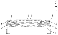
- FIG. 10 is a diagram illustrating a slide rail assembly according to an example not according to the present invention. Moreover, the first supporting portion 42 and the second supporting portion 44 of the slide rail assembly of the first embodiment are integrated on the first bracket 24. Difference between the example and the invention is that: a first supporting portion 302 and a second supporting portion 304 are arranged on the first rail 300.
- the first supporting portion 302 and the second supporting portion 304 are two extended arms laterally extended from the first wall 30a and the second wall 30b of the first rail 22. According to the above example not according to the invention, when the second rail 26 is located at the extended position P2 relative to the first rail 300, the first supporting portion 302 and the first wall 34a of the second rail 26 support each other, and the second supporting portion 304 and the second wall 34b of the second rail 26 support each other.
Landscapes
- Engineering & Computer Science (AREA)
- Computer Hardware Design (AREA)
- General Engineering & Computer Science (AREA)
- Microelectronics & Electronic Packaging (AREA)
- Drawers Of Furniture (AREA)
Claims (8)
- Ensemble de glissière (20), comprenant:un premier rail (22); ayant une première partie d'extrémité (E1) et une deuxième partie d'extrémité (E2) éloignée de la première partie d'extrémité;un premier support (24, 200) disposé de manière adjacente à la première partie d'extrémité (E1) du premier rail (22), le premier support (24, 200) comprenant une paroi latérale (46) et au moins un élément de montage (48) adjacent à la paroi latérale (46) et configuré pour monter le premier rail (22) sur un premier montant (54a), le deuxième ensemble de glissière comprend en outre un deuxième rail (26), un troisième rail (28) et un deuxième support (29);le deuxième support (29) est disposé de manière adjacente à la deuxième partie d'extrémité (E2) du premier rail (22), le deuxième support (29) comprenant une plaque latérale (50) et au moins un deuxième élément de montage (52) adjacent à la plaque latérale (50); et configuré pour monter le premier rail (22) sur un deuxième montant (54b); etle second rail (26) est mobile par rapport au premier rail (22), dans lequel le second rail (26) comprend une première paroi (34a), une deuxième paroi (34b) et une paroi longitudinale (36) reliée entre la première paroi (34a) et la deuxième paroi (34b) du second rail (26);dans lequel une première partie de support (42, 202) est agencée sur le premier support (24, 200), la première partie de support (42, 202) comprend deux premières sections de support (42a, 42b), dans lequel une des deux premières sections de support (42a) est configurée pour supporter la première paroi (34a) du second rail (26) dans une direction transversale et une autre des deux premières sections de support (42b) est configurée pour supporter la première paroi (34a) du second rail (26) dans une direction de hauteur, la première paroi (34a) du deuxième rail (26) est située entre la première section de support (42a) et la paroi latérale (46) du premier support (24), pour empêcher le deuxième rail (26) d'être déplacé dans la direction transversale, la direction transversale et la direction de la hauteur sont sensiblement perpendiculaires l'une par rapport à l'autre;dans lequel une deuxième partie de support (44, 204) est agencée sur le premier support (24, 200), la deuxième partie de support (44, 204) comprend deux deuxièmes sections de support (44a, 44b), dans lequel une des deux deuxièmes sections de support (44a) est configurée pour supporter la deuxième paroi (34b) du second rail (26) dans une direction transversale et une autre des deux deuxièmes sections de support (44b) est configurée pour supporter la deuxième paroi (34b) du second rail (26) dans une direction de hauteur, la deuxième paroi (34b) du deuxième rail (26) est située entre la deuxième section de support (44a) et la paroi latérale (46) du premier support (24), pour empêcher le deuxième rail (26) d'être déplacé dans la direction transversale;dans lequel, lorsque le second rail (26) est situé dans une position étendue par rapport au premier rail (22), la première paroi (34a) du second rail (26) est située entre la première section de support (42a) et la paroi latérale (46) du premier support (24) et la deuxième paroi (34b) du second rail (26) est située entre la deuxième section de support (44a) et la paroi latérale (46) du premier support (24), de sorte que la première partie de support (42, 202) et la première paroi (34a) du second rail (26) se supportent mutuellement, la première section de support (42a) supporte un côté latéral de la première paroi (34a) du second rail (26), la deuxième partie de support (44, 204) et la deuxième paroi (34b) du second rail (26) se supportent mutuellement, et la deuxième section de support (44a) supporte un côté latéral de la deuxième paroi (34b) du second rail (26);caractérisé en ce que:
lorsque le deuxième rail (26) est situé dans une position rétractée par rapport au premier rail (22), la première partie de support (42, 202) et la première paroi (34a) du deuxième rail (26) ne s'engagent pas l'une dans l'autre. - Ensemble de glissière (20) de la revendication 1, caractérisé en ce que lorsque le second rail (26) est situé à la position étendue par rapport au premier rail (22), la paroi latérale (46) du premier support (24, 200) et la paroi longitudinale (36) du second rail (26) se supportent mutuellement.
- Ensemble de glissière (20) de la revendication 1, caractérisé en ce que le premier rail (22) comprend une première paroi (30a), une deuxième paroi (30b) et une paroi longitudinale (32) reliée entre la première paroi (30a) et la deuxième paroi (30b) du premier rail (22), un premier passage (33) est défini par la première paroi (30a), la deuxième paroi (30b) et la paroi longitudinale (32) du premier rail (22), le premier passage (33) est configuré pour recevoir le second rail (26), le second rail (26) est monté de manière mobile dans le premier passage (33).
- Ensemble de glissière (20) de la revendication 3, caractérisé en outre par un deuxième passage (37) défini par la première paroi (34a), la deuxième paroi (34b) et la paroi longitudinale (36) du deuxième rail (26), le deuxième passage (37) est configuré pour recevoir le troisième rail (28), le troisième rail (28) est monté de manière mobile dans le deuxième passage (37).
- Ensemble de glissière (20) de la revendication 4, caractérisé en ce que le troisième rail (28) comprend une première paroi (38a), une deuxième paroi (38b) et une paroi longitudinale (40) reliée entre la première paroi (38a) et la deuxième paroi (38b) du troisième rail (28), au moins une de la première paroi (30a) et de la deuxième paroi (30b) du premier rail (22) comprend une première section de paroi (X1) et une deuxième section de paroi (X2) pliée par rapport à la première section de paroi (X1), une largeur transversale est formée entre la deuxième section de paroi (X2) du premier rail (22) et la paroi longitudinale (32) du premier rail (22), au moins une de la première paroi (38a) et de la deuxième paroi (38b) du troisième rail (28) comprend une première section de paroi (K1) pliée par rapport à la paroi longitudinale (40) du troisième rail (28) et une deuxième section de paroi (K2) pliée par rapport à la première section de paroi (K1) du troisième rail (28), la deuxième section de paroi (K2) du troisième rail (28) s'étend dans le deuxième passage (37) du deuxième rail (26), la deuxième section de paroi (K2) du troisième rail (28) est située dans la largeur transversale.
- Ensemble de glissière (20) selon la revendication 5, caractérisé en ce que la paroi longitudinale (40) du troisième rail (28) et les deuxièmes sections de paroi (X2) du premier rail (22) sont sensiblement sur un même plan (H).
- Ensemble de glissière (20) de la revendication 5 ou 6, caractérisé en ce qu'au moins l'une de la première paroi (34a) et de la deuxième paroi (34b) du deuxième rail (26) comprend une première section d'extension (M1) pliée par rapport à la paroi longitudinale (36) du deuxième rail (26), une première section de pliage (B1) pliée par rapport à la première section d'extension (M1), une deuxième section d'extension (M2) pliée par rapport à la première section de pliage (B1) et une deuxième section de pliage (B2) pliée par rapport à la deuxième section d'extension (M2), la deuxième section d'extension (M2) du deuxième rail (26) et la première section de paroi (K1) du troisième rail (28) sont capables de se supporter mutuellement.
- Ensemble de glissières (20) de l'une quelconque des revendications 1 à 7, caractérisé en ce que la paroi longitudinale (36) du deuxième rail (26) comprend une première section longitudinale (L1), une deuxième section longitudinale (L2) et une section intermédiaire (L3), la première section longitudinale (L1) et la deuxième section longitudinale (L2) sont respectivement pliées à partir de deux extrémités opposées de la section intermédiaire (L3).
Applications Claiming Priority (1)
| Application Number | Priority Date | Filing Date | Title |
|---|---|---|---|
| TW108127486A TWI704886B (zh) | 2019-07-31 | 2019-07-31 | 滑軌總成 |
Publications (2)
| Publication Number | Publication Date |
|---|---|
| EP3772242A1 EP3772242A1 (fr) | 2021-02-03 |
| EP3772242B1 true EP3772242B1 (fr) | 2022-08-24 |
Family
ID=68501352
Family Applications (1)
| Application Number | Title | Priority Date | Filing Date |
|---|---|---|---|
| EP19207857.4A Active EP3772242B1 (fr) | 2019-07-31 | 2019-11-08 | Glissiere et son support |
Country Status (4)
| Country | Link |
|---|---|
| US (1) | US10729032B1 (fr) |
| EP (1) | EP3772242B1 (fr) |
| JP (1) | JP6870059B2 (fr) |
| TW (1) | TWI704886B (fr) |
Families Citing this family (2)
| Publication number | Priority date | Publication date | Assignee | Title |
|---|---|---|---|---|
| CN112471795A (zh) * | 2020-12-09 | 2021-03-12 | 海宁市启程智能装备有限公司 | 抽屉滑轨的安装结构 |
| TWI739718B (zh) * | 2021-03-10 | 2021-09-11 | 川湖科技股份有限公司 | 滑軌機構及其滑軌套件 |
Family Cites Families (9)
| Publication number | Priority date | Publication date | Assignee | Title |
|---|---|---|---|---|
| US6834923B2 (en) | 2003-02-10 | 2004-12-28 | Jonathan Manufacturing Corporation | Miniature solid bearing slide assembly |
| TW582693U (en) * | 2003-05-14 | 2004-04-01 | Hon Hai Prec Ind Co Ltd | Rail assembly |
| CN101803832A (zh) | 2010-04-23 | 2010-08-18 | 雅固拉国际精密工业(苏州)有限公司 | 一种用于服务器机架的滑轨 |
| CN102438422B (zh) | 2010-09-29 | 2016-04-06 | 鸿富锦精密工业(深圳)有限公司 | 滑轨装置 |
| CN105246376B (zh) | 2013-03-13 | 2017-12-05 | 雅固拉国际有限公司 | 狭长抽屉滑轨 |
| US9328769B1 (en) * | 2015-01-27 | 2016-05-03 | King Slide Works Co., Ltd. | Slide rail assembly and bracket device thereof |
| TWI552670B (zh) * | 2015-10-06 | 2016-10-01 | King Slide Works Co Ltd | 滑軌總成及其托架裝置 |
| US10117352B2 (en) * | 2016-01-06 | 2018-10-30 | King Slide Works Co., Ltd. | Slide rail assembly |
| TWI592791B (zh) | 2016-04-13 | 2017-07-21 | Server slide reinforcement structure |
-
2019
- 2019-07-31 TW TW108127486A patent/TWI704886B/zh active
- 2019-10-17 US US16/656,564 patent/US10729032B1/en active Active
- 2019-11-08 EP EP19207857.4A patent/EP3772242B1/fr active Active
- 2019-11-13 JP JP2019205130A patent/JP6870059B2/ja active Active
Also Published As
| Publication number | Publication date |
|---|---|
| US10729032B1 (en) | 2020-07-28 |
| JP2021023781A (ja) | 2021-02-22 |
| TWI704886B (zh) | 2020-09-21 |
| EP3772242A1 (fr) | 2021-02-03 |
| JP6870059B2 (ja) | 2021-05-12 |
| TW202106204A (zh) | 2021-02-16 |
Similar Documents
| Publication | Publication Date | Title |
|---|---|---|
| US10806256B1 (en) | Slide rail assembly | |
| US9861197B2 (en) | Slide rail assembly | |
| US11627682B2 (en) | Rack-mounted device and electronic apparatus | |
| EP3457826B1 (fr) | Système de rayonnage et son ensemble de rail de coulissement | |
| EP3772242B1 (fr) | Glissiere et son support | |
| EP3352547B1 (fr) | Ensemble de rails de glissement | |
| EP3637968B1 (fr) | Ensemble de gestion de câbles | |
| EP3258754B1 (fr) | Système de rayonnage et ses ensembles de rail de coulissement | |
| EP3979775B1 (fr) | Ensemble rail coulissant | |
| EP3914057B1 (fr) | Ensemble rail coulissant | |
| EP3772243B1 (fr) | Glissiere et son support | |
| EP4057786B1 (fr) | Mécanisme de rail coulissant et son kit de rail coulissant | |
| US20130100619A1 (en) | Bracing structure for expansion cards of different sizes and electronic device having the bracing structure | |
| EP3993583B1 (fr) | Ensemble rail coulissant | |
| CN112333973B (zh) | 滑轨总成 | |
| EP3057386A1 (fr) | Ensemble de rail de glissement | |
| EP4576959B1 (fr) | Kit de rail coulissant | |
| CN119730128A (zh) | 支撑总成 | |
| JP7706840B2 (ja) | 電気電子機器収納用ラック | |
| EP4529373A1 (fr) | Ensemble support | |
| CN114449828A (zh) | 滑轨总成 | |
| CN117896933A (zh) | 一种整体式5g通讯柜 | |
| CN112312713A (zh) | 滑轨机构 | |
| CN113928229A (zh) | 车载多媒体主机外壳及主机安装结构 |
Legal Events
| Date | Code | Title | Description |
|---|---|---|---|
| STAA | Information on the status of an ep patent application or granted ep patent |
Free format text: STATUS: EXAMINATION IS IN PROGRESS |
|
| PUAI | Public reference made under article 153(3) epc to a published international application that has entered the european phase |
Free format text: ORIGINAL CODE: 0009012 |
|
| 17P | Request for examination filed |
Effective date: 20200225 |
|
| AK | Designated contracting states |
Kind code of ref document: A1 Designated state(s): AL AT BE BG CH CY CZ DE DK EE ES FI FR GB GR HR HU IE IS IT LI LT LU LV MC MK MT NL NO PL PT RO RS SE SI SK SM TR |
|
| AX | Request for extension of the european patent |
Extension state: BA ME |
|
| GRAP | Despatch of communication of intention to grant a patent |
Free format text: ORIGINAL CODE: EPIDOSNIGR1 |
|
| STAA | Information on the status of an ep patent application or granted ep patent |
Free format text: STATUS: GRANT OF PATENT IS INTENDED |
|
| INTG | Intention to grant announced |
Effective date: 20220518 |
|
| GRAS | Grant fee paid |
Free format text: ORIGINAL CODE: EPIDOSNIGR3 |
|
| GRAA | (expected) grant |
Free format text: ORIGINAL CODE: 0009210 |
|
| STAA | Information on the status of an ep patent application or granted ep patent |
Free format text: STATUS: THE PATENT HAS BEEN GRANTED |
|
| AK | Designated contracting states |
Kind code of ref document: B1 Designated state(s): AL AT BE BG CH CY CZ DE DK EE ES FI FR GB GR HR HU IE IS IT LI LT LU LV MC MK MT NL NO PL PT RO RS SE SI SK SM TR |
|
| REG | Reference to a national code |
Ref country code: CH Ref legal event code: EP |
|
| REG | Reference to a national code |
Ref country code: IE Ref legal event code: FG4D |
|
| REG | Reference to a national code |
Ref country code: AT Ref legal event code: REF Ref document number: 1514603 Country of ref document: AT Kind code of ref document: T Effective date: 20220915 Ref country code: DE Ref legal event code: R096 Ref document number: 602019018600 Country of ref document: DE |
|
| REG | Reference to a national code |
Ref country code: LT Ref legal event code: MG9D |
|
| REG | Reference to a national code |
Ref country code: NL Ref legal event code: MP Effective date: 20220824 |
|
| PG25 | Lapsed in a contracting state [announced via postgrant information from national office to epo] |
Ref country code: SE Free format text: LAPSE BECAUSE OF FAILURE TO SUBMIT A TRANSLATION OF THE DESCRIPTION OR TO PAY THE FEE WITHIN THE PRESCRIBED TIME-LIMIT Effective date: 20220824 Ref country code: RS Free format text: LAPSE BECAUSE OF FAILURE TO SUBMIT A TRANSLATION OF THE DESCRIPTION OR TO PAY THE FEE WITHIN THE PRESCRIBED TIME-LIMIT Effective date: 20220824 Ref country code: PT Free format text: LAPSE BECAUSE OF FAILURE TO SUBMIT A TRANSLATION OF THE DESCRIPTION OR TO PAY THE FEE WITHIN THE PRESCRIBED TIME-LIMIT Effective date: 20221226 Ref country code: NO Free format text: LAPSE BECAUSE OF FAILURE TO SUBMIT A TRANSLATION OF THE DESCRIPTION OR TO PAY THE FEE WITHIN THE PRESCRIBED TIME-LIMIT Effective date: 20221124 Ref country code: NL Free format text: LAPSE BECAUSE OF FAILURE TO SUBMIT A TRANSLATION OF THE DESCRIPTION OR TO PAY THE FEE WITHIN THE PRESCRIBED TIME-LIMIT Effective date: 20220824 Ref country code: LV Free format text: LAPSE BECAUSE OF FAILURE TO SUBMIT A TRANSLATION OF THE DESCRIPTION OR TO PAY THE FEE WITHIN THE PRESCRIBED TIME-LIMIT Effective date: 20220824 Ref country code: LT Free format text: LAPSE BECAUSE OF FAILURE TO SUBMIT A TRANSLATION OF THE DESCRIPTION OR TO PAY THE FEE WITHIN THE PRESCRIBED TIME-LIMIT Effective date: 20220824 Ref country code: FI Free format text: LAPSE BECAUSE OF FAILURE TO SUBMIT A TRANSLATION OF THE DESCRIPTION OR TO PAY THE FEE WITHIN THE PRESCRIBED TIME-LIMIT Effective date: 20220824 |
|
| REG | Reference to a national code |
Ref country code: AT Ref legal event code: MK05 Ref document number: 1514603 Country of ref document: AT Kind code of ref document: T Effective date: 20220824 |
|
| PG25 | Lapsed in a contracting state [announced via postgrant information from national office to epo] |
Ref country code: PL Free format text: LAPSE BECAUSE OF FAILURE TO SUBMIT A TRANSLATION OF THE DESCRIPTION OR TO PAY THE FEE WITHIN THE PRESCRIBED TIME-LIMIT Effective date: 20220824 Ref country code: IS Free format text: LAPSE BECAUSE OF FAILURE TO SUBMIT A TRANSLATION OF THE DESCRIPTION OR TO PAY THE FEE WITHIN THE PRESCRIBED TIME-LIMIT Effective date: 20221224 Ref country code: HR Free format text: LAPSE BECAUSE OF FAILURE TO SUBMIT A TRANSLATION OF THE DESCRIPTION OR TO PAY THE FEE WITHIN THE PRESCRIBED TIME-LIMIT Effective date: 20220824 Ref country code: GR Free format text: LAPSE BECAUSE OF FAILURE TO SUBMIT A TRANSLATION OF THE DESCRIPTION OR TO PAY THE FEE WITHIN THE PRESCRIBED TIME-LIMIT Effective date: 20221125 |
|
| PG25 | Lapsed in a contracting state [announced via postgrant information from national office to epo] |
Ref country code: SM Free format text: LAPSE BECAUSE OF FAILURE TO SUBMIT A TRANSLATION OF THE DESCRIPTION OR TO PAY THE FEE WITHIN THE PRESCRIBED TIME-LIMIT Effective date: 20220824 Ref country code: RO Free format text: LAPSE BECAUSE OF FAILURE TO SUBMIT A TRANSLATION OF THE DESCRIPTION OR TO PAY THE FEE WITHIN THE PRESCRIBED TIME-LIMIT Effective date: 20220824 Ref country code: ES Free format text: LAPSE BECAUSE OF FAILURE TO SUBMIT A TRANSLATION OF THE DESCRIPTION OR TO PAY THE FEE WITHIN THE PRESCRIBED TIME-LIMIT Effective date: 20220824 Ref country code: DK Free format text: LAPSE BECAUSE OF FAILURE TO SUBMIT A TRANSLATION OF THE DESCRIPTION OR TO PAY THE FEE WITHIN THE PRESCRIBED TIME-LIMIT Effective date: 20220824 Ref country code: CZ Free format text: LAPSE BECAUSE OF FAILURE TO SUBMIT A TRANSLATION OF THE DESCRIPTION OR TO PAY THE FEE WITHIN THE PRESCRIBED TIME-LIMIT Effective date: 20220824 Ref country code: AT Free format text: LAPSE BECAUSE OF FAILURE TO SUBMIT A TRANSLATION OF THE DESCRIPTION OR TO PAY THE FEE WITHIN THE PRESCRIBED TIME-LIMIT Effective date: 20220824 |
|
| REG | Reference to a national code |
Ref country code: DE Ref legal event code: R097 Ref document number: 602019018600 Country of ref document: DE |
|
| PG25 | Lapsed in a contracting state [announced via postgrant information from national office to epo] |
Ref country code: SK Free format text: LAPSE BECAUSE OF FAILURE TO SUBMIT A TRANSLATION OF THE DESCRIPTION OR TO PAY THE FEE WITHIN THE PRESCRIBED TIME-LIMIT Effective date: 20220824 Ref country code: EE Free format text: LAPSE BECAUSE OF FAILURE TO SUBMIT A TRANSLATION OF THE DESCRIPTION OR TO PAY THE FEE WITHIN THE PRESCRIBED TIME-LIMIT Effective date: 20220824 |
|
| PG25 | Lapsed in a contracting state [announced via postgrant information from national office to epo] |
Ref country code: MC Free format text: LAPSE BECAUSE OF FAILURE TO SUBMIT A TRANSLATION OF THE DESCRIPTION OR TO PAY THE FEE WITHIN THE PRESCRIBED TIME-LIMIT Effective date: 20220824 Ref country code: AL Free format text: LAPSE BECAUSE OF FAILURE TO SUBMIT A TRANSLATION OF THE DESCRIPTION OR TO PAY THE FEE WITHIN THE PRESCRIBED TIME-LIMIT Effective date: 20220824 |
|
| PLBE | No opposition filed within time limit |
Free format text: ORIGINAL CODE: 0009261 |
|
| REG | Reference to a national code |
Ref country code: CH Ref legal event code: PL |
|
| STAA | Information on the status of an ep patent application or granted ep patent |
Free format text: STATUS: NO OPPOSITION FILED WITHIN TIME LIMIT |
|
| REG | Reference to a national code |
Ref country code: BE Ref legal event code: MM Effective date: 20221130 |
|
| PG25 | Lapsed in a contracting state [announced via postgrant information from national office to epo] |
Ref country code: LI Free format text: LAPSE BECAUSE OF NON-PAYMENT OF DUE FEES Effective date: 20221130 Ref country code: CH Free format text: LAPSE BECAUSE OF NON-PAYMENT OF DUE FEES Effective date: 20221130 |
|
| 26N | No opposition filed |
Effective date: 20230525 |
|
| PG25 | Lapsed in a contracting state [announced via postgrant information from national office to epo] |
Ref country code: SI Free format text: LAPSE BECAUSE OF FAILURE TO SUBMIT A TRANSLATION OF THE DESCRIPTION OR TO PAY THE FEE WITHIN THE PRESCRIBED TIME-LIMIT Effective date: 20220824 Ref country code: LU Free format text: LAPSE BECAUSE OF NON-PAYMENT OF DUE FEES Effective date: 20221108 |
|
| PG25 | Lapsed in a contracting state [announced via postgrant information from national office to epo] |
Ref country code: FR Free format text: LAPSE BECAUSE OF NON-PAYMENT OF DUE FEES Effective date: 20221130 Ref country code: BE Free format text: LAPSE BECAUSE OF NON-PAYMENT OF DUE FEES Effective date: 20221130 |
|
| PG25 | Lapsed in a contracting state [announced via postgrant information from national office to epo] |
Ref country code: CY Free format text: LAPSE BECAUSE OF FAILURE TO SUBMIT A TRANSLATION OF THE DESCRIPTION OR TO PAY THE FEE WITHIN THE PRESCRIBED TIME-LIMIT Effective date: 20220824 |
|
| PG25 | Lapsed in a contracting state [announced via postgrant information from national office to epo] |
Ref country code: MK Free format text: LAPSE BECAUSE OF FAILURE TO SUBMIT A TRANSLATION OF THE DESCRIPTION OR TO PAY THE FEE WITHIN THE PRESCRIBED TIME-LIMIT Effective date: 20220824 Ref country code: IT Free format text: LAPSE BECAUSE OF FAILURE TO SUBMIT A TRANSLATION OF THE DESCRIPTION OR TO PAY THE FEE WITHIN THE PRESCRIBED TIME-LIMIT Effective date: 20220824 Ref country code: HU Free format text: LAPSE BECAUSE OF FAILURE TO SUBMIT A TRANSLATION OF THE DESCRIPTION OR TO PAY THE FEE WITHIN THE PRESCRIBED TIME-LIMIT; INVALID AB INITIO Effective date: 20191108 |
|
| PG25 | Lapsed in a contracting state [announced via postgrant information from national office to epo] |
Ref country code: BG Free format text: LAPSE BECAUSE OF FAILURE TO SUBMIT A TRANSLATION OF THE DESCRIPTION OR TO PAY THE FEE WITHIN THE PRESCRIBED TIME-LIMIT Effective date: 20220824 |
|
| REG | Reference to a national code |
Ref country code: DE Ref legal event code: R082 Ref document number: 602019018600 Country of ref document: DE Representative=s name: STRAUS, ALEXANDER, DIPL.-CHEM.UNIV. DR.PHIL., DE |
|
| PG25 | Lapsed in a contracting state [announced via postgrant information from national office to epo] |
Ref country code: MT Free format text: LAPSE BECAUSE OF FAILURE TO SUBMIT A TRANSLATION OF THE DESCRIPTION OR TO PAY THE FEE WITHIN THE PRESCRIBED TIME-LIMIT Effective date: 20220824 |
|
| PGFP | Annual fee paid to national office [announced via postgrant information from national office to epo] |
Ref country code: GB Payment date: 20250909 Year of fee payment: 7 |
|
| PGFP | Annual fee paid to national office [announced via postgrant information from national office to epo] |
Ref country code: IE Payment date: 20250909 Year of fee payment: 7 |
|
| PG25 | Lapsed in a contracting state [announced via postgrant information from national office to epo] |
Ref country code: TR Free format text: LAPSE BECAUSE OF FAILURE TO SUBMIT A TRANSLATION OF THE DESCRIPTION OR TO PAY THE FEE WITHIN THE PRESCRIBED TIME-LIMIT Effective date: 20220824 |
|
| PGFP | Annual fee paid to national office [announced via postgrant information from national office to epo] |
Ref country code: DE Payment date: 20250910 Year of fee payment: 7 |