EP3772352A1 - Implantat mit integrierter gelenkstruktur - Google Patents
Implantat mit integrierter gelenkstruktur Download PDFInfo
- Publication number
- EP3772352A1 EP3772352A1 EP19190022.4A EP19190022A EP3772352A1 EP 3772352 A1 EP3772352 A1 EP 3772352A1 EP 19190022 A EP19190022 A EP 19190022A EP 3772352 A1 EP3772352 A1 EP 3772352A1
- Authority
- EP
- European Patent Office
- Prior art keywords
- implant
- implant according
- basic structure
- node
- struts
- Prior art date
- Legal status (The legal status is an assumption and is not a legal conclusion. Google has not performed a legal analysis and makes no representation as to the accuracy of the status listed.)
- Withdrawn
Links
- 239000007943 implant Substances 0.000 title claims abstract description 78
- 210000003709 heart valve Anatomy 0.000 claims abstract description 36
- 238000005452 bending Methods 0.000 abstract description 7
- 238000007789 sealing Methods 0.000 abstract description 2
- 238000002513 implantation Methods 0.000 description 8
- 210000001765 aortic valve Anatomy 0.000 description 7
- 238000000418 atomic force spectrum Methods 0.000 description 6
- 210000003484 anatomy Anatomy 0.000 description 5
- 210000000709 aorta Anatomy 0.000 description 5
- 238000010586 diagram Methods 0.000 description 5
- 208000004434 Calcinosis Diseases 0.000 description 3
- 239000008280 blood Substances 0.000 description 3
- 210000004369 blood Anatomy 0.000 description 3
- 230000002308 calcification Effects 0.000 description 3
- 230000001788 irregular Effects 0.000 description 3
- 230000007704 transition Effects 0.000 description 3
- 206010003664 atrial septal defect Diseases 0.000 description 2
- 238000002788 crimping Methods 0.000 description 2
- 230000006870 function Effects 0.000 description 2
- 239000000463 material Substances 0.000 description 2
- 238000009958 sewing Methods 0.000 description 2
- 229910001285 shape-memory alloy Inorganic materials 0.000 description 2
- 210000002073 venous valve Anatomy 0.000 description 2
- 241001136792 Alle Species 0.000 description 1
- 206010007556 Cardiac failure acute Diseases 0.000 description 1
- 206010007558 Cardiac failure chronic Diseases 0.000 description 1
- 208000031481 Pathologic Constriction Diseases 0.000 description 1
- 230000001154 acute effect Effects 0.000 description 1
- 238000004026 adhesive bonding Methods 0.000 description 1
- 208000013914 atrial heart septal defect Diseases 0.000 description 1
- 230000015572 biosynthetic process Effects 0.000 description 1
- 230000017531 blood circulation Effects 0.000 description 1
- 230000001684 chronic effect Effects 0.000 description 1
- 230000000694 effects Effects 0.000 description 1
- 238000001727 in vivo Methods 0.000 description 1
- 238000003780 insertion Methods 0.000 description 1
- 230000037431 insertion Effects 0.000 description 1
- 210000005240 left ventricle Anatomy 0.000 description 1
- 238000000034 method Methods 0.000 description 1
- 238000002324 minimally invasive surgery Methods 0.000 description 1
- 229910001000 nickel titanium Inorganic materials 0.000 description 1
- HLXZNVUGXRDIFK-UHFFFAOYSA-N nickel titanium Chemical compound [Ti].[Ti].[Ti].[Ti].[Ti].[Ti].[Ti].[Ti].[Ti].[Ti].[Ti].[Ni].[Ni].[Ni].[Ni].[Ni].[Ni].[Ni].[Ni].[Ni].[Ni].[Ni].[Ni].[Ni].[Ni] HLXZNVUGXRDIFK-UHFFFAOYSA-N 0.000 description 1
- 230000002085 persistent effect Effects 0.000 description 1
- 210000004872 soft tissue Anatomy 0.000 description 1
- 238000001356 surgical procedure Methods 0.000 description 1
- 230000009466 transformation Effects 0.000 description 1
- 230000002792 vascular Effects 0.000 description 1
Images



Classifications
-
- A—HUMAN NECESSITIES
- A61—MEDICAL OR VETERINARY SCIENCE; HYGIENE
- A61F—FILTERS IMPLANTABLE INTO BLOOD VESSELS; PROSTHESES; DEVICES PROVIDING PATENCY TO, OR PREVENTING COLLAPSING OF, TUBULAR STRUCTURES OF THE BODY, e.g. STENTS; ORTHOPAEDIC, NURSING OR CONTRACEPTIVE DEVICES; FOMENTATION; TREATMENT OR PROTECTION OF EYES OR EARS; BANDAGES, DRESSINGS OR ABSORBENT PADS; FIRST-AID KITS
- A61F2/00—Filters implantable into blood vessels; Prostheses, i.e. artificial substitutes or replacements for parts of the body; Appliances for connecting them with the body; Devices providing patency to, or preventing collapsing of, tubular structures of the body, e.g. stents
- A61F2/82—Devices providing patency to, or preventing collapsing of, tubular structures of the body, e.g. stents
- A61F2/86—Stents in a form characterised by the wire-like elements; Stents in the form characterised by a net-like or mesh-like structure
- A61F2/90—Stents in a form characterised by the wire-like elements; Stents in the form characterised by a net-like or mesh-like structure characterised by a net-like or mesh-like structure
- A61F2/91—Stents in a form characterised by the wire-like elements; Stents in the form characterised by a net-like or mesh-like structure characterised by a net-like or mesh-like structure made from perforated sheets or tubes, e.g. perforated by laser cuts or etched holes
- A61F2/915—Stents in a form characterised by the wire-like elements; Stents in the form characterised by a net-like or mesh-like structure characterised by a net-like or mesh-like structure made from perforated sheets or tubes, e.g. perforated by laser cuts or etched holes with bands having a meander structure, adjacent bands being connected to each other
-
- A—HUMAN NECESSITIES
- A61—MEDICAL OR VETERINARY SCIENCE; HYGIENE
- A61F—FILTERS IMPLANTABLE INTO BLOOD VESSELS; PROSTHESES; DEVICES PROVIDING PATENCY TO, OR PREVENTING COLLAPSING OF, TUBULAR STRUCTURES OF THE BODY, e.g. STENTS; ORTHOPAEDIC, NURSING OR CONTRACEPTIVE DEVICES; FOMENTATION; TREATMENT OR PROTECTION OF EYES OR EARS; BANDAGES, DRESSINGS OR ABSORBENT PADS; FIRST-AID KITS
- A61F2/00—Filters implantable into blood vessels; Prostheses, i.e. artificial substitutes or replacements for parts of the body; Appliances for connecting them with the body; Devices providing patency to, or preventing collapsing of, tubular structures of the body, e.g. stents
- A61F2/02—Prostheses implantable into the body
- A61F2/24—Heart valves ; Vascular valves, e.g. venous valves; Heart implants, e.g. passive devices for improving the function of the native valve or the heart muscle; Transmyocardial revascularisation [TMR] devices; Valves implantable in the body
- A61F2/2412—Heart valves ; Vascular valves, e.g. venous valves; Heart implants, e.g. passive devices for improving the function of the native valve or the heart muscle; Transmyocardial revascularisation [TMR] devices; Valves implantable in the body with soft flexible valve members, e.g. tissue valves shaped like natural valves
- A61F2/2418—Scaffolds therefor, e.g. support stents
-
- A—HUMAN NECESSITIES
- A61—MEDICAL OR VETERINARY SCIENCE; HYGIENE
- A61F—FILTERS IMPLANTABLE INTO BLOOD VESSELS; PROSTHESES; DEVICES PROVIDING PATENCY TO, OR PREVENTING COLLAPSING OF, TUBULAR STRUCTURES OF THE BODY, e.g. STENTS; ORTHOPAEDIC, NURSING OR CONTRACEPTIVE DEVICES; FOMENTATION; TREATMENT OR PROTECTION OF EYES OR EARS; BANDAGES, DRESSINGS OR ABSORBENT PADS; FIRST-AID KITS
- A61F2/00—Filters implantable into blood vessels; Prostheses, i.e. artificial substitutes or replacements for parts of the body; Appliances for connecting them with the body; Devices providing patency to, or preventing collapsing of, tubular structures of the body, e.g. stents
- A61F2/82—Devices providing patency to, or preventing collapsing of, tubular structures of the body, e.g. stents
- A61F2/86—Stents in a form characterised by the wire-like elements; Stents in the form characterised by a net-like or mesh-like structure
- A61F2/90—Stents in a form characterised by the wire-like elements; Stents in the form characterised by a net-like or mesh-like structure characterised by a net-like or mesh-like structure
- A61F2/91—Stents in a form characterised by the wire-like elements; Stents in the form characterised by a net-like or mesh-like structure characterised by a net-like or mesh-like structure made from perforated sheets or tubes, e.g. perforated by laser cuts or etched holes
- A61F2/915—Stents in a form characterised by the wire-like elements; Stents in the form characterised by a net-like or mesh-like structure characterised by a net-like or mesh-like structure made from perforated sheets or tubes, e.g. perforated by laser cuts or etched holes with bands having a meander structure, adjacent bands being connected to each other
- A61F2002/9155—Adjacent bands being connected to each other
- A61F2002/91583—Adjacent bands being connected to each other by a bridge, whereby at least one of its ends is connected along the length of a strut between two consecutive apices within a band
-
- A—HUMAN NECESSITIES
- A61—MEDICAL OR VETERINARY SCIENCE; HYGIENE
- A61F—FILTERS IMPLANTABLE INTO BLOOD VESSELS; PROSTHESES; DEVICES PROVIDING PATENCY TO, OR PREVENTING COLLAPSING OF, TUBULAR STRUCTURES OF THE BODY, e.g. STENTS; ORTHOPAEDIC, NURSING OR CONTRACEPTIVE DEVICES; FOMENTATION; TREATMENT OR PROTECTION OF EYES OR EARS; BANDAGES, DRESSINGS OR ABSORBENT PADS; FIRST-AID KITS
- A61F2250/00—Special features of prostheses classified in groups A61F2/00 - A61F2/26 or A61F2/82 or A61F9/00 or A61F11/00 or subgroups thereof
- A61F2250/0014—Special features of prostheses classified in groups A61F2/00 - A61F2/26 or A61F2/82 or A61F9/00 or A61F11/00 or subgroups thereof having different values of a given property or geometrical feature, e.g. mechanical property or material property, at different locations within the same prosthesis
- A61F2250/0029—Special features of prostheses classified in groups A61F2/00 - A61F2/26 or A61F2/82 or A61F9/00 or A61F11/00 or subgroups thereof having different values of a given property or geometrical feature, e.g. mechanical property or material property, at different locations within the same prosthesis differing in bending or flexure capacity
Definitions
- the present invention relates to an implant with an openwork, hollow cylindrical and / or hollow truncated cone-shaped basic structure, which is composed of a plurality of struts and a plurality of nodes (connectors) connecting the struts, with at least two struts being connected to each other at each node.
- the implant assumes a compressed state and an expanded state.
- Prostheses Medical implants (prostheses), in particular intraluminal endoprostheses, for a wide variety of applications are known from the prior art in great variety.
- Prostheses are, for example, endoprostheses to close persistent foramen ovals (PFO), endoprostheses to close an ASG (atrial septum defect, atrioseptal defect), aortic prostheses and prostheses in the area of hard and soft tissue.
- a prominent representative of the prostheses are heart valve prostheses, which are used as an artificial replacement for a natural heart valve to prevent acute or chronic heart failure.
- Heart valve prostheses are used using the open surgical technique or, recently, increasingly minimally invasive.
- transcatheter aortic valve implantation is of particular importance today.
- a heart valve prosthesis for the aortic valve is inserted transfemorally or transcapitally by means of a catheter.
- Such a heart valve prosthesis often has an openwork hollow cylinder and / or hollow truncated cone-shaped (tubular) basic structure as a support structure, and a flexible one attached within the basic structure Valve leaflet and a skirt, which seals the area of the annulus on the natural heart valve after it has been inserted into the heart to prevent the blood from flowing back into the vessel (aorta) after it has been expelled.
- the skirt is attached to the basic structure and closes the gap between the annulus and the basic structure.
- the basic structure itself is open at both ends in the longitudinal direction.
- Stents which are used to treat stenoses (vascular constrictions), are also often used as implants. They usually have a perforated hollow cylindrical (tubular) basic structure that is open at both ends in the longitudinal direction. Such an implant is often inserted into the vessel to be treated by means of a catheter and is used to support the vessel over a longer period of time (months to years). By using stents, narrowed areas in the vessels can be expanded.
- the basic structure of the above-described implants is often composed of cells (meshes), which are formed from a large number of struts (webs, struts), for example from struts that form zigzag or meander-shaped structures. At the ends of the cells arranged in the longitudinal direction or the sides, two or more than two struts meet in a so-called node, which connect the cells and the struts to one another.
- Such an implant which is inserted with the aid of a catheter, or its basic structure, usually takes on two states, namely a compressed state with a small diameter and an expanded state with a larger diameter.
- the implant In the compressed state, the implant can be introduced into the heart or the vessel by means of the catheter through narrow vessels and, for example, positioned in the area of the aortic valve or the venous valve.
- the transition from the compressed state to the expanded state takes place by expanding the support structure, for example by means of a balloon.
- the expansion of the support structure causes the heart valve prosthesis to unfold.
- the transition to the expanded state takes place in the case of a self-expanding implant when the transformation temperature is exceeded.
- the heart valve prosthesis is brought into the correct position and, for example, after a catheter sleeve has been withdrawn, it is unfolded in the proximal direction. In some situations, however, the catheter sleeve also has to be pushed back at least partially in the distal direction over the heart valve prosthesis (resheathing, recapture) in order to enable repositioning of the heart valve prosthesis.
- the tightness of an implant can vary greatly depending on the design of the implant in the case of calcifications and deposits on the respective vessel or the heart, i.e. e.g. if the annulus deviates from the circular shape.
- a high degree of bending flexibility of the implant is advantageous for this, so that the implant can adapt to different anatomies.
- the implants are provided with a skirt on the outside, which is suitable for adapting to the various anatomies. Stents with insufficient radial force or very large cell structures that do not adapt to the shape of the annulus or calcifications tend to leak paravalvularly, which can lead to a life-threatening situation for the patient. At the moment it does not appear to be feasible to adapt the shape of the implant exactly to the individual shape of the vessel or the annulus before insertion.
- the object of the present invention is thus to create an implant which avoids the above disadvantages and in particular ensures a reliable sealing of the vessel or annulus into which the implant is inserted.
- the implant according to the invention has a basic structure in which at least some of the nodes each have a cross-shaped continuous recess.
- the cross-shaped recess is made in the node in such a way that it is completely surrounded or enclosed by the material of the basic structure.
- the recess extends in the radial direction of the basic structure through the material of the basic structure in the area of a node.
- the implant according to the invention is preferably a heart valve prosthesis or a venous valve prosthesis.
- the implant is designed as a heart valve prosthesis comprising a basic structure or a basic framework (stent) and a valve arrangement fastened therein, the advantages of the present invention are particularly evident.
- the recesses according to the invention reduce the area moment of inertia of the nodes (connectors) and thus increase the bending flexibility compared with conventional nodes without such a recess.
- the basic structure is thus more flexible and adapts better to irregular calcified anatomies.
- the knot according to the invention with a cruciform recess has a relatively high stability in the case of tensile or compressive forces that act on the basic structure of the implant, as can occur in the catheter or when stressed by the heart valve forces.
- the torsional stability of the nodes is also guaranteed.
- the basic structure of the implant according to the invention has lower resheathing forces which, moreover, only increase gradually (i.e. not suddenly) in an advantageous manner.
- the basic structure preferably consists of a shape memory alloy, for example nitinol.
- At least two struts are connected to one another at a node.
- the struts form meshes or cells, for example four struts form a diamond-shaped cell.
- the nodes are each arranged at the ends of the meshes or cells.
- each cross-shaped recess has a centrally arranged central section as well as at least four side sections (arms) extending cross-shaped from this central section, which overall form the “cross”.
- the recess can be described as butterfly-shaped in the broader sense.
- the width b of the central section in the circumferential direction is at least 0.2, preferably 1.5 and at most 5 times the extension of the length l of the central section.
- the length of each central section is the same as the width of the central section in the circumferential direction.
- each side section is configured in the shape of a circular section at the end opposite the central section. In a further exemplary embodiment, each side section is of the same length.
- the width A of the node in the longitudinal direction is 0.2 to 5 times the width B of the node in the circumferential direction U. This results in a comparatively high stability of the basic structure with regard to tensile or compressive forces, as in the catheter or at Load after implantation can occur.
- the width A of the node in the longitudinal direction is the width B of the node in the circumferential direction U.
- two opposing projections protrude into the recess and extend in the circumferential direction.
- two opposing projections protrude into the recess, which projections extend in the longitudinal direction. Because of their spacing, these projections limit in particular the bending flexibility of the basic structure in the respective direction.
- the cross-shaped, continuous recess is provided in each node of a section of the basic structure which forms the inflow area of the implant when the implant is used as intended (after implantation).
- the prosthesis is implanted in place of a natural heart valve, for example the Aortic valve implanted.
- the basic structure of the heart valve prosthesis then sits in the aortic annulus and the valve arrangement arranged therein takes on the function of the natural aortic valve. With the valve in the open position, the blood flows from the left ventricle through the basic structure into the aorta. Return flow from the aorta is blocked by the valve assembly.
- the area of the basic structure which lies in the direction of the blood flowing from the ventricle from the valve arrangement is referred to as the inflow area of the implant (in this case the heart valve prosthesis).
- valve leaflets and / or a skirt are attached to the basic structure.
- the fastening is preferably done by sewing or gluing.
- FIG. 1 an inventive implant in the form of a heart valve prosthesis 10 with a basic structure 20 is shown.
- the basic structure 20 (also referred to as a heart valve stent) forms a supporting framework for the implant.
- the basic structure 20 is a hollow cylindrical frame, which can vary in its diameter along the longitudinal direction L, such as Fig. 2 shows to be optimally fitted into the structure anatomically given by the patient.
- the basic structure 20 can have at least one section in the shape of a hollow truncated cone for this purpose.
- the heart valve prosthesis 10 ( Fig. 1 ) consists for example of a shape memory alloy, has a smaller diameter that is positioned in the annulus area and a larger diameter that extends into the ascending aorta. Both areas are connected by an S-shaped transition zone.
- the heart valve prosthesis 10 also has three valve leaflets 30 and a skirt 40, which are attached to the basic structure 20 by means of sewing. The skirt 40 is intended to seal the heart valve prosthesis 10 in such a way that the blood that has passed the heart valve prosthesis 10 cannot flow past the heart valve prosthesis 10 to the side.
- Fig. 2 shows the arrangement of a heart valve prosthesis 10 according to the invention after implantation in the area of the annulus 50 of an aortic valve.
- the natural heart valve 55 is displaced by the artificial heart valve prosthesis 10.
- the heart valve prosthesis 10 takes over the function of the natural heart valve 55 as soon as the implantation is completed.
- Heart valve prosthesis 10 Since an irregular anatomy can be present in the area of the annulus 50, for example due to the presence of calcifications, it is essential for proper functioning of the Heart valve prosthesis 10 requires that the basic structure 20 has a high degree of bending flexibility in the region of the inflow in order to be able to adapt to such a geometry. This avoids paravalvular leakage.
- the basic structure 20 has a cross-shaped or butterfly-shaped continuous recess (opening) 27 at least in this area.
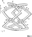
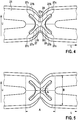
- a recess is in the Figures 3 and 4th shown in detail, in which sections of the implant with basic structure 20 are shown, which consists of a plurality of struts 21 which are connected to one another via nodes 24. In each case four struts 21 form how Fig. 4 can be seen, diamond-shaped cells or meshes 23 from.
- Each recess 27 has a central section 27 a, which is arranged approximately in the middle in the cross-shaped recess 27 and forms the intersection of the four side sections 27 b of the recess 27.
- Each side section 27b forms an end 27c which is opposite the central section 27a.
- the central section 27a is delimited in the circumferential direction U by two opposing projections 28, the distance between them being the width b (see Fig. 5 , for the sake of clarity, separately Fig. 4 is cited.
- the dimensions A and B of the node, b and l of the central section can be seen) of the central section 27a.
- the central section 27a of the recess 27 is delimited by the opposing projections 29, the distance between which is referred to as the length l of the central section 27a.
- the shape of the recess 27 can be designed such that the recess 27 at the ends 27c of each side section 27b is designed in the shape of a segment of a circle.
- the recesses 27 according to the invention reduce the geometrical moment of inertia of the respective node 24 and thus increase the bending flexibility compared to nodes without such a recess.
- the basic structure 20 is thus more flexible and adapts better to an irregular anatomy.
- the torsional stability of the nodes 24 is also guaranteed.
- the recesses have an effect on the radial force curve (hysteresis), as can be seen from the in Fig. 6 shown in the diagram.
- a radial force curve 105 of an implant according to the invention and a radial force curve 106 of an implant that does not have a cross-shaped recess in the node are compared with one another.
- the diameter of the basic structure (in mm) is plotted on the X axis 101 and the radial force (in N) is plotted on the Y axis 102.
- the area 103 surrounded by a dash-dot line designates the working area of the implant according to the invention clinically in vivo.
- Diagram 100 shows that with the same COF (Chronic Outward Force), which ensures the contact pressure of the stent in the aorta, the implant according to the invention has a lower RRF (Radial Resistive Force), which is responsible for the reaction forces during crimping and resheathening is.
- RRF Ring Resistive Force
- the increase in RRF is slower, which means that the required resheathing force does not increase suddenly but gradually.
Landscapes
- Health & Medical Sciences (AREA)
- Biomedical Technology (AREA)
- Engineering & Computer Science (AREA)
- Cardiology (AREA)
- Heart & Thoracic Surgery (AREA)
- Oral & Maxillofacial Surgery (AREA)
- Transplantation (AREA)
- Vascular Medicine (AREA)
- Life Sciences & Earth Sciences (AREA)
- Animal Behavior & Ethology (AREA)
- General Health & Medical Sciences (AREA)
- Public Health (AREA)
- Veterinary Medicine (AREA)
- Optics & Photonics (AREA)
- Physics & Mathematics (AREA)
- Prostheses (AREA)
Abstract
Die Erfindung betrifft ein Implantat (10), beispielsweise eine Herzklappenprothese, mit einer durchbrochenen, hohlzylinderförmigen und/oder hohlkegelstumpfförmigen Grundstruktur (20), die sich aus einer Vielzahl von Streben (21) und die Streben (21) miteinander verbindenden Knoten (24) zusammensetzt, wobei an jedem Knoten (24) jeweils mindestens zwei Streben (21) miteinander verbunden sind. Um eine sichere Abdichtung des Gefäßes oder Annulus, in das das Implantat eingebracht ist, zu gewährleisten, weist mindestens ein Teil der Knoten (24) jeweils eine kreuzförmige durchgehende Aussparung (27) auf, welche die Biegeflexibilität der Grundstruktur (20) erhöht.
Description
- Die vorliegende Erfindung betrifft ein Implantat mit einer durchbrochenen, hohlzylinderförmigen und/oder hohlkegelstumpfförmigen Grundstruktur, die sich aus einer Vielzahl von Streben und einer Vielzahl von die Streben miteinander verbindenden Knoten (Verbinder) zusammensetzt, wobei an jedem Knoten jeweils mindestens zwei Streben miteinander verbunden sind. Das Implantat nimmt einen komprimierten Zustand und einen expandierten Zustand ein.
- Medizinische Implantate (Prothesen), insbesondere intraluminale Endoprothesen, für unterschiedlichste Anwendungen sind in großer Vielfalt aus dem Stand der Technik bekannt. Prothesen sind z.B. Endoprothesen zum Verschließen von persistierenden Foramen Ovale (PFO), Endoprothesen zum Verschließen eines ASG (Vorhofscheidewanddefekt, Atrioseptaldefekt), Aortenprothesen sowie Prothesen im Bereich des Hart- und Weichgewebes. Ein prominenter Vertreter der Prothesen sind Herzklappenprothesen, welche als künstlicher Ersatz für eine natürliche Herzklappe zur Verhinderung einer akuten oder chronischen Herzinsuffizienz verwendet werden. Herzklappenprothesen werden nach der offen-chirurgischen Technik oder in letzter Zeit zunehmend minimal-invasiv eingesetzt.
- Für die Anwendung minimal-invasiver Verfahren im Bereich des Herzklappenersatzes ist heute insbesondere die Transkatheter-Aortenklappenimplantation (englisch: transcatheter aortic valve implantation TAVI) von Bedeutung. Bei dieser Implantationstechnik wird mittels eines Katheters eine Herzklappenprothese für die Aortenklappe u.a. transfemoral oder transkapital eingesetzt. Eine solche Herzklappenprothese besitzt häufig eine durchbrochene hohlzylinder- und/oder hohlkegelstumpfförmige (röhrenförmige) Grundstruktur als Stützstruktur, innerhalb der Grundstruktur angebrachte biegsame Klappensegel (Leaflet) sowie einen Skirt, welches den Bereich des Annulus an der natürlichen Herzklappe nach dem Einsetzen in das Herz abdichtet, um ein Rückfließen des Bluts nach Ausstoß in das Gefäß (Aorta) zu vermeiden. Hierfür ist das Skirt an der Grundstruktur befestigt und verschließt den Zwischenraum zwischen Annulus und der Grundstruktur. Die Grundstruktur selbst ist an beiden Enden in Längsrichtung offen.
- Als Implantate werden außerdem häufig Stents eingesetzt, die zur Behandlung von Stenosen (Gefäßverengungen) dienen. Sie weisen meist eine durchbrochene hohlzylinderförmige (rohrförmige) Grundstruktur auf, die an beiden Enden in Längsrichtung offen ist. Ein derartiges Implantat wird häufig mittels eines Katheters in das zu behandelnde Gefäß eingesetzt und dient dazu, das Gefäß über einen längeren Zeitraum (Monate bis Jahre) zu stützen. Durch den Einsatz von Stents können verengte Bereiche in den Gefäßen erweitert werden.
- Die Grundstruktur von oben beschriebenen Implantaten setzt sich häufig aus Zellen (Maschen) zusammen, welche aus einer Vielzahl von Streben (Stege, Struts), beispielsweise aus zick-zack- oder mäanderförmige Strukturen formenden Streben, gebildet werden. An den in Längsrichtung bzw. den Seiten angeordneten Enden der Zellen treffen sich jeweils zwei oder mehr als zwei Streben in einem sogenannten Knoten, welche die Zellen und die Streben miteinander verbinden.
- Ein derartiges Implantat, welches kathetergestützt eingesetzt wird, beziehungsweise seine Grundstruktur nimmt üblicherweise zwei Zustände ein, nämlich einen komprimierten Zustand mit einem kleinen Durchmesser und einen expandierten Zustand mit einem größeren Durchmesser. Im komprimierten Zustand kann das Implantat mittels des Katheters durch enge Gefäße hindurch in das Herz oder das Gefäß eingeführt und z.B. im Bereich der Aortenklappe oder der Venenklappe positioniert werden. Der Übergang von dem komprimierten Zustand in den expandierten Zustand erfolgt durch Expandieren der Stützstruktur beispielsweise mittels eines Ballons. Die Expansion der Stützstruktur bewirkt bei der Herzklappenprothese deren Entfaltung. Alternativ erfolgt der Übergang in den expandierten Zustand bei einem selbstexpandierenden Implantat bei einer Überschreitung der Transformationstemperatur.
- Mittels des Katheters wird die Herzklappenprothese in die richtige Position gebracht und beispielsweise nach Zurückziehen einer Katheterhülse in proximale Richtung entfaltet. Hierbei muss die Katheterhülse jedoch in manchen Situationen auch zumindest teilweise wieder in distale Richtung über die Herzklappenprothese geschoben werden (Resheathing, Wiedereinfangen), um eine Repositionierung der Herzklappenprothese zu ermöglichen.
- Die Dichtigkeit eines Implantats kann bei Verkalkungen und Ablagerungen an dem jeweiligen Gefäßes oder des Herzens, das heißt z.B. bei Abweichungen des Annulus von der Kreisform, je nach Design des Implantats, stark variieren. Dafür ist eine hohe Biegeflexibilität des Implantats vorteilhaft, so dass sich das Implantat verschiedenen Anatomien anpassen kann. Ferner werden die Implantate an der AuOßenseite mit einem Skirt versehen, der geeignet ist, sich den verschiedenen Anatomien anzupassen. Stents mit zu wenig Radialkraft oder sehr großen Zellstrukturen, die sich der Annulusform bzw. Verkalkungen nicht anpassen, neigen zu paravalvularen Leckagen, die für den Patienten eine lebensbedrohliche Situation hervorrufen können. Derzeit erscheint es nicht realisierbar, die Form des Implantats vor dem Einsetzen exakt der individuellen Form des Gefäßes bzw. des Annulus anzupassen.
- Zudem besteht das Problem, dass herkömmliche Implantate beim Resheathen starke axiale und radiale Kräfte erzeugen, welche zu bleibenden Verformungen am Katheter führen können. Damit ist die Ausbildung von hohen Radialkräften durch ein Implantat nicht erwünscht, weil die verwendeten Kathetersysteme hohen Resheathingkräften nur begrenzt standhalten können.
- Die Aufgabe der vorliegenden Erfindung besteht somit darin, ein Implantat zu schaffen, welches die obigen Nachteile vermeidet und insbesondere eine sichere Abdichtung des Gefäßes oder Annulus, in das das Implantat eingebracht ist, gewährleistet.
- Die obige Aufgabe wird gelöst durch das Implantat mit den Merkmalen des Anspruchs 1.
- Das erfindungsgemäße Implantat besitzt insbesondere eine Grundstruktur, bei der mindestens ein Teil der Knoten jeweils eine kreuzförmige durchgehende Aussparung aufweist. Die kreuzförmige Aussparung ist derart in dem Knoten angebracht, dass sie vollständig von Material der Grundstruktur umgeben oder umschlossen ist. Die Aussparung geht in radialer Richtung der Grundstruktur durch das Material der Grundstruktur im Bereich eines Knotens hindurch. Das erfindungsgemäße Implantat ist vorzugsweise eine Herzklappenprothese oder eine Venenklappenprothese. Bei einer Ausbildung des Implantats als Herzklappenprothese umfassend eine Grundstruktur bzw. ein Grundgerüst (Stent) und eine darin befestigte Klappenanordnung kommen die Vorteile der vorliegenden Erfindung besonders zum Tragen.
- Die erfindungsgemäßen Aussparungen verringern das Flächenträgheitsmoment der Knoten (Verbinder) und erhöhen somit die Biegeflexibilität verglichen mit herkömmlichen Knoten ohne eine derartige Aussparung. Die Grundstruktur ist somit biegeweicher und passt sich besser unregelmäßigen verkalkten Anatomien an. Im Vergleich zu anderen Grundstrukturen ergibt sich, dass der erfindungsgemäße Knoten mit kreuzförmiger Aussparung eine relativ hohe Stabilität bei Zug- oder Druckkräften aufweist, die auf die Grundstruktur des Implantats wirken, wie sie im Katheter oder bei Belastung mit den Herzklappenkräften auftreten können. Auch die Torsionsstabilität der Knoten ist gewährleistet. Zudem besitzt die Grundstruktur des erfindungsgemäßen Implantats, wie unten noch genauer erläutert wird, geringere Resheathingkräfte, die zudem in vorteilhafter Weise lediglich allmählich (d.h. nicht sprunghaft) ansteigen.
- Die Grundstruktur besteht vorzugsweise aus einer Formgedächtnislegierung, beispielsweise Nitinol.
- In einem bevorzugten Ausführungsbeispiel sind an einem Knoten mindestens zwei Streben, weiter bevorzugt drei und weiter vorzugsweise mindestens vier Streben miteinander verbunden. Bei der Grundstruktur bilden die Streben Maschen oder Zellen aus, beispielsweise vier Streben eine rautenförmige Zelle. Die Knoten sind jeweils an den Enden der Maschen oder Zellen angeordnet.
- Eine Weiterbildung der Erfindung zeichnet sich dadurch aus, dass jede kreuzförmige Aussparung einen mittig angeordneten Zentralabschnitt sowie mindestens vier von diesem Zentralabschnitt kreuzförmig abgehende Seitenabschnitte (Arme) aufweist, die insgesamt das "Kreuz" ausbilden. Mit einem anderen Wort kann die Aussparung als im weiteren Sinne schmetterlingsförmig beschrieben werden. Die Breite b des Zentralabschnitts in Umfangsrichtung beträgt mindestens 0,2, vorzugsweise 1,5 und maximal 5 Mal die Ausdehnung der Länge l des Zentralabschnitts. In einem weiteren Ausführungsbeispiel der Erfindung beträgt die Länge jedes Zentralabschnitts dieselbe Ausdehnung wie die Breite des Zentralabschnitts in Umfangsrichtung.
- In einem weiteren Ausführungsbeispiel ist jeder Seitenabschnitt an dem Zentralabschnitt gegenüber liegenden Ende kreisabschnittsförmig ausgebildet. In einem weiteren Ausführungsbeispiel ist jeder Seitenabschnitt gleich lang.
- In einer Weiterbildung der Erfindung beträgt die Breite A des Knotens in Längsrichtung 0,2 bis 5 Mal die Breite B des Knotens in Umfangsrichtung U. Hierdurch wird eine vergleichsweise hohe Stabilität der Grundstruktur in Bezug auf Zug- oder Druckkräfte, wie sie im Katheter oder bei Belastung nach Implantation auftreten können, gewährleistet. In einer Ausführungsform beträgt die Breite A des Knotens in Längsrichtung die Breite B des Knotens in Umfangsrichtung U.
- In einem weiteren Ausführungsbeispiel ragen in die Aussparung zwei einander gegenüber liegende Vorsprünge hinein, die sich in Umfangsrichtung erstrecken. Alternativ oder zusätzlich ragen in die Aussparung zwei einander gegenüber liegende Vorsprünge hinein, die sich in Längsrichtung erstrecken. Diese Vorsprünge begrenzen durch ihren Abstand insbesondere die Biegeflexibilität der Grundstruktur in die jeweilige Richtung.
- Es ist weiter von Vorteil, dass die kreuzförmige durchgehende Aussparung in jedem Knoten eines Abschnitts der Grundstruktur vorgesehen ist, der im bestimmungsgemäßen Gebrauch des Implantates (nach Implantation) den Einströmbereich des Implantates bildet. Im der bevorzugten Ausgestaltung der Erfindung als Herzklappenprothese wird bei Implantation die Prothese an die Stelle einer natürlichen Herzklappe beispielsweise der Aortenklappe implantiert. Die Grundstruktur der Herzklappenprothese sitzt dann im Aortenannulus und die darin angeordnete Klappenanordnung übernimmt die Funktion der natürlichen Aortenklappe. Das Blut strömt vom linken Ventrikel in der Offenstellung der Klappe durch die Grundstruktur in die Aorta. Der Rückstrom von der Aorta wird durch die Klappenanordnung blockiert. Der Bereich der Grundstruktur der in Richtung des vom Ventrikel strömenden Blutes von der Klappenanordnung liegt, wird als Einströmbereich des Implantates (in diesem Fall der Herzklappenprothese) bezeichnet.
- In einem Ausführungsbeispiel der Erfindung sind an der Grundstruktur mindestens zwei Klappensegel und/oder ein Skirt befestigt. Die Befestigung erfolgt dabei vorzugsmäßig durch Nähen oder Kleben.
- Weitere Ziele, Merkmale, Vorteile und Anwendungsmöglichkeiten der Erfindung ergeben sich auch aus der nachfolgenden Beschreibung von Ausführungsbeispielen der Erfindung anhand der Figuren. Dabei bilden alle beschriebenen und/oder bildlich dargestellten Merkmale für sich oder in beliebiger Kombination den Gegenstand der Erfindung, auch unabhängig von ihrer Zusammenfassung in den einzelnen Ansprüchen oder deren Rückbezug.
- Es zeigen schematisch
- Fig. 1
- ein erfindungsgemäßes Implantat in einer perspektivischen Ansicht von der Seite;
- Fig. 2
- das Implantat gemäß
Fig. 1 nach der Implantation im Bereich einer natürlichen Aortenklappe in einer teilweise geschnittenen Darstellung; - Fig. 3
- die Grundstruktur eines erfindungsgemäßen Implantats in einer perspektivischen Ansicht von der Seite;
- Fig. 4 - 5
- einen Ausschnitt der Grundstruktur gemäß
Fig. 3 im Bereich eines Knotens; und - Fig. 6
- ein Diagramm, in dem der Radialkraftverlauf (in N) über dem Durchmesser (in mm) einer Grundstruktur ohne spezielle Knotenformen im Vergleich mit einer erfindungsgemäßen Grundstruktur beim Crimpen vom Nenndurchmesser auf 18 French und Freilassen auf den Nenndurchmesser eingezeichnet ist.
- In
Fig. 1 ist ein erfindungsgemäßes Implantat in Form einer Herzklappenprothese 10 mit einer Grundstruktur 20 dargestellt. Die Grundstruktur 20 (auch als Herzklappenstent bezeichnet) bildet ein stützendes Gerüst für das Implantat. Die Grundstruktur 20 ist ein hohlzylinderförmiges Gerüst, das entlang der Längsrichtung L in seinem Durchmesser variiert kann, um, wieFig. 2 zeigt, optimal in die durch den Patienten anatomisch vorgegebene Struktur eingepasst zu werden. Alternativ oder zusätzlich kann die Grundstruktur 20 hierfür mindestens einen hohlkegelstumpfförmigen Abschnitt aufweisen. - Die Herzklappenprothese 10 (
Fig. 1 ) besteht beispielsweise aus einer Formgedächnislegierung, hat einen kleineren Durchmesser der im Annulusbereich positioniert wird und einen größeren Durchmesser der in die aufsteigende Aorta reicht. Beide Bereiche werden durch eine s-förmige Übergangszone verbunden. Die Herzklappenprothese 10 weist ferner drei Klappensegel 30 sowie ein Skirt 40 auf, welche mittels Vernähen an der Grundstruktur 20 befestigt sind. Das Skirt 40 soll die Herzklappenprothese 10 so abdichten, dass das Blut, dass die Herzklappenprothese 10 passiert hat, nicht seitlich an der Herzklappenprothese 10 vorbeifließen kann. -
Fig. 2 zeigt die Anordnung einer erfindungsgemäßen Herzklappenprothese 10 nach dem Implantieren im Bereich des Annulus 50 einer Aortenklappe. Die natürliche Herzklappe 55 wird hierbei durch die künstliche Herzklappenprothese 10 verdrängt. Die Herzklappenprothese 10 übernimmt die Funktion der natürlichen Herzklappe 55 sobald die Implantation abgeschlossen ist. - Da im Bereich des Annulus 50 eine unregelmäßige Anatomie beispielsweise aufgrund von vorhandenen Verkalkungen vorliegen kann, ist es für eine ordnungsgemäße Funktion der Herzklappenprothese 10 erforderlich, dass die Grundstruktur 20 im Bereich des Inflows eine hohe Biegeflexibilität aufweist, um sich an eine derartige Geometrie anpassen zu können. Hierdurch werden paravalvulare Leckagen vermieden.
- Um eine derartige hohe Biegeflexibilität der Grundstruktur 20 zumindest im Bereich des Inflows zu gewährleisten, weist die Grundstruktur 20 zumindest in diesem Bereich jeweils eine kreuzförmige oder schmetterlingsförmige durchgehende Aussparung (Öffnung) 27 auf. Eine derartige Aussparung ist in den
Figuren 3 und4 im Detail gezeigt, in denen Ausschnitte des Implantats mit Grundstruktur 20 gezeigt sind, die aus einer Vielzahl von Streben 21 besteht, welche über Knoten 24 miteinander verbunden sind. Jeweils vier Streben 21 bilden, wieFig. 4 zu entnehmen ist, rautenförmige Zellen oder Maschen 23 aus. Jede Aussparung 27 besitzt einen Zentralabschnitt 27a, der etwa mittig in der kreuzförmigen Aussparung 27 angeordnet ist und den Schnittpunkt der vier Seitenabschnitte 27b der Aussparung 27 bildet. Jeder Seitenabschnitt 27b bildet ein Ende 27c aus, das dem Zentralabschnitt 27a gegenüberliegt. Der Zentralabschnitt 27a wird in Umfangsrichtung U begrenzt durch zwei einander gegenüberliegende Vorsprünge 28, deren Abstand als Breite b (sieheFig. 5 , die der besseren Übersicht halber gesondert zuFig. 4 angeführt wird. Hier werden die Ausmaße A und B des Knotens, b und l des Zentralabschnittes ersichtlich) des Zentralabschnitts 27a bezeichnet wird. In Längsrichtung L wird der Zentralabschnitt 27a der Aussparung 27 durch die einander gegenüberliegenden Vorsprünge 29 begrenzt, deren Abstand als Länge l des Zentralabschnitts 27a bezeichnet wird. - Wie in
Fig. 3 gezeigt ist, kann die Form der Aussparung 27 derart gestaltet sein, dass die Aussparung 27 an den Enden 27c jedes Seitenabschnitts 27b kreisabschnittsförmig gestaltet ist. - Die erfindungsgemäßen Aussparungen 27 verringern das Flächenträgheitsmoment des jeweiligen Knotens 24 und erhöhen somit die Biegeflexibilität verglichen mit Knoten ohne eine solche Aussparung. Die Grundstruktur 20 ist somit biegeweicher und passt sich besser einer unregelmäßigen Anatomie an. Auch die Torsionsstabilität der Knoten 24 ist gewährleistet.
- Außerdem haben die Aussparungen einen Effekt auf die Radialkraftkurve (Hysterese), wie dies anschaulich aus dem in
Fig. 6 gezeigten Diagramm hervorgeht. In dem Diagramm werden eine Radialkraftkurve 105 eines erfindungsgemäßen Implantats und eine Radialkraftkurve 106 eines Implantats, das in den Knoten eine kreuzförmige Aussparung nicht aufweist, miteinander verglichen. Hierbei ist auf der X-Achse 101 der Durchmesser der Grundstruktur (in mm) und auf der Y-Achse 102 die Radialkraft (in N) aufgetragen. Der mit einer Strich-Punkt-Linie umrandeten Bereich 103 bezeichnet den Arbeitsbereich des erfindungsgemäßen Implantats klinisch in vivo. - Aus dem Diagramm 100 ergibt sich, dass bei gleichem COF (Chronic Outward Force), welcher für den Anpressdruck des Stents in der Aorta sorgt, das erfindungsgemäße Implantat ein geringeres RRF (Radial Resistive Force) aufweist, welcher für die Reaktionskräfte beim Crimpen und Resheathen verantwortlich ist. Damit wird die Hysterese schmaler und es muss weniger Verformungsarbeit beim Freilassen und Resheathen verrichtet werden, was kleinere Resheathing-Kräfte bedingt. Außerdem verläuft der Anstieg des RRF langsamer, was dazu führt, dass die erforderliche Resheathing-Kraft nicht sprunghaft sondern allmählich ansteigt. Es befindet sich demnach immer nur ein kleiner Teil des Implantats mit geringem Durchmesser auf dem oberen RRF-Plateau während der andere Teil des Implantats mit einem größeren Durchmesser im Bereich des unteren RRF-Plateau verbleibt. Eine Limitation des Prinzips besteht darin, dass auch das COF bei größeren Durchmessern leicht abfällt. Dies kann durch größere Durchmesser der Grundstruktur kompensiert werden, so dass der klinische Einsatzbereich wieder im konstanten COF Bereich liegt.
-
- 10
- Herzklappenprothese
- 20
- Grundstruktur
- 21
- Strebe
- 23
- Zelle
- 24
- Knoten
- 27
- Aussparung
- 27a
- Zentralabschnitt der Aussparung 27
- 27b
- Seitenabschnitt der Aussparung 27
- 27c
- Ende des Seitenabschnitts 27b der Aussparung 27
- 28
- Vorsprung
- 29
- Vorsprung
- 30
- Klappensegel
- 40
- Skirt
- 50
- Annulus
- 55
- natürliche Herzklappe
- 100
- Diagramm
- 101
- x-Achse
- 102
- y-Achse
- 103
- Arbeitsbereich des Implantats
- 105
- Radialkraftkurve des erfindungsgemäßen Implantats
- 106
- Radialkraftkurve eines Vergleichsimplantats ohne Aussparung
- In Anbetracht der gesamten obigen Offenbarung, umfasst die vorliegende Erfindung ferner die folgenden nummerierten Ausführungsformen:
- 1. Implantat (10) mit einer durchbrochenen, hohlzylinderförmigen und/oder hohlkegelstumpfförmigen Grundstruktur (20), die sich aus einer Vielzahl von Streben (21) und die Streben (21) miteinander verbindenden Knoten (24) zusammensetzt, wobei an jedem Knoten (24) jeweils mindestens zwei Streben (21) miteinander verbunden sind, dadurch gekennzeichnet, dass
mindestens ein Teil der Knoten (24) jeweils eine kreuzförmige durchgehende Aussparung (27) aufweist. - 2. Implantat nach Ausführungsform 1, dadurch gekennzeichnet, dass an einem Knoten (24) mindestens zwei Streben (21), vorzugsweise mindestens vier Streben (21) miteinander verbunden sind.
- 3. Implantat nach einer der vorhergehenden Ausführungsformen, dadurch gekennzeichnet, dass jede Aussparung einen Zentralabschnitt (27a) sowie mindestens vier von diesem Zentralabschnitt kreuzförmig abgehende Seitenabschnitte (27b) aufweist.
- 4. Implantat nach einer der vorhergehenden Ausführungsformen, dadurch gekennzeichnet, dass die Breite b des Zentralabschnitts (27a) in Umfangsrichtung (U) mindestens 0,2 und maximal 5 Mal die Ausdehnung der Länge l des Zentralabschnitts beträgt.
- 5. Implantat nach einer der vorhergehenden Ausführungsformen, dadurch gekennzeichnet, dass die Länge jedes Seitenabschnitts (27b) gleich lang ist.
- 6. Implantat nach einer der vorhergehenden Ausführungsformen, dadurch gekennzeichnet, dass die Länge jedes Zentralabschnitts dieselbe Ausdehnung wie die Breite des Zentralabschnitts in Umfangsrichtung aufweist.
- 7. Implantat nach einer der vorhergehenden Ausführungsformen, dadurch gekennzeichnet, dass die Breite A des Knotens in Längsrichtung 0,2 bis 5 Mal die Breite B des Knotens in Umfangsrichtung U ist.
- 8. Implantat nach einer der vorhergehenden Ausführungsformen, dadurch gekennzeichnet, dass die Breite (B) des Knotens (24) in Umfangsrichtung U die Breite A des Knotens in Längsrichtung aufweist.
- 9. Implantat nach einer der vorhergehenden Ausführungsformen, dadurch gekennzeichnet, dass in die Aussparung (27) zwei einander gegenüberliegende Vorsprünge (28) hineinragen, die sich in Umfangsrichtung (U) erstrecken.
- 10. Implantat nach einer der vorhergehenden Ausführungsformen, dadurch gekennzeichnet, dass in die Aussparung zwei einander gegenüberliegende Vorsprünge (29) hineinragen, die sich in Längsrichtung (L) erstrecken.
- 11. Implantat nach einer der vorhergehenden Ausführungsformen, dadurch gekennzeichnet, dass die kreuzförmige durchgehende Aussparung (27) in jedem Knoten (24) eines Abschnitts der Grundstruktur (20) vorgesehen ist.
- 12. Implantat nach einer der vorhergehenden Ausführungsformen, dadurch gekennzeichnet, dass das Implantat als Herzklappenprothese ausgebildet ist und eine Grundstruktur (20) mit einer darin angeordnete Klappenanordnung umfasst.
- 13. Implantat nach Ausführungsform 12, dadurch gekennzeichnet, dass an der Grundstruktur (20) drei Klappensegel (30) und/oder ein Skirt (40) befestigt ist.
- 14. Implantat nach einer der vorhergehenden Ausführungsformen, dadurch gekennzeichnet, dass die Mehrzahl, bevorzugt alle, Knoten (24), die jeweils eine kreuzförmige durchgehende Aussparung (27) aufweisen, im Einströmbereich des Implantates angeordnet sind.
Claims (14)
- Implantat (10) mit einer durchbrochenen, hohlzylinderförmigen und/oder hohlkegelstumpfförmigen Grundstruktur (20), die sich aus einer Vielzahl von Streben (21) und die Streben (21) miteinander verbindenden Knoten (24) zusammensetzt, wobei an jedem Knoten (24) jeweils mindestens zwei Streben (21) miteinander verbunden sind, dadurch gekennzeichnet, dass mindestens ein Teil der Knoten (24) jeweils eine kreuzförmige durchgehende Aussparung (27) aufweist.
- Implantat nach Anspruch 1, dadurch gekennzeichnet, dass an einem Knoten (24) mindestens zwei Streben (21), vorzugsweise mindestens vier Streben (21) miteinander verbunden sind.
- Implantat nach einem der vorhergehenden Ansprüche, dadurch gekennzeichnet, dass jede Aussparung einen Zentralabschnitt (27a) sowie mindestens vier von diesem Zentralabschnitt kreuzförmig abgehende Seitenabschnitte (27b) aufweist.
- Implantat nach einem der vorhergehenden Ansprüche, dadurch gekennzeichnet, dass die Breite b des Zentralabschnitts (27a) in Umfangsrichtung (U) mindestens 0,2 und maximal 5 Mal die Ausdehnung der Länge l des Zentralabschnitts beträgt.
- Implantat nach einem der vorhergehenden Ansprüche, dadurch gekennzeichnet, dass die Länge jedes Seitenabschnitts (27b) gleich lang ist.
- Implantat nach einem der vorhergehenden Ansprüche, dadurch gekennzeichnet, dass die Länge jedes Zentralabschnitts dieselbe Ausdehnung wie die Breite des Zentralabschnitts in Umfangsrichtung aufweist.
- Implantat nach einem der vorhergehenden Ansprüche, dadurch gekennzeichnet, dass die Breite A des Knotens in Längsrichtung 0,2 bis 5 Mal die Breite B des Knotens in Umfangsrichtung U ist.
- Implantat nach einem der vorhergehenden Ansprüche, dadurch gekennzeichnet, dass die Breite (B) des Knotens (24) in Umfangsrichtung U die Breite A des Knotens in Längsrichtung aufweist.
- Implantat nach einem der vorhergehenden Ansprüche, dadurch gekennzeichnet, dass in die Aussparung (27) zwei einander gegenüberliegende Vorsprünge (28) hineinragen, die sich in Umfangsrichtung (U) erstrecken.
- Implantat nach einem der vorhergehenden Ansprüche, dadurch gekennzeichnet, dass in die Aussparung zwei einander gegenüberliegende Vorsprünge (29) hineinragen, die sich in Längsrichtung (L) erstrecken.
- Implantat nach einem der vorhergehenden Ansprüche, dadurch gekennzeichnet, dass die kreuzförmige durchgehende Aussparung (27) in jedem Knoten (24) eines Abschnitts der Grundstruktur (20) vorgesehen ist.
- Implantat nach einem der vorhergehenden Ansprüche, dadurch gekennzeichnet, dass das Implantat als Herzklappenprothese ausgebildet ist und eine Grundstruktur (20) mit einer darin angeordnete Klappenanordnung umfasst.
- Implantat nach Anspruch 12, dadurch gekennzeichnet, dass an der Grundstruktur (20) drei Klappensegel (30) und/oder ein Skirt (40) befestigt ist.
- Implantat nach einem der vorangehenden Ansprüche, dadurch gekennzeichnet, dass die Mehrzahl, bevorzugt alle, Knoten (24), die jeweils eine kreuzförmige durchgehende Aussparung (27) aufweisen, im Einströmbereich des Implantates angeordnet sind.
Priority Applications (1)
| Application Number | Priority Date | Filing Date | Title |
|---|---|---|---|
| EP19190022.4A EP3772352A1 (de) | 2019-08-05 | 2019-08-05 | Implantat mit integrierter gelenkstruktur |
Applications Claiming Priority (1)
| Application Number | Priority Date | Filing Date | Title |
|---|---|---|---|
| EP19190022.4A EP3772352A1 (de) | 2019-08-05 | 2019-08-05 | Implantat mit integrierter gelenkstruktur |
Publications (1)
| Publication Number | Publication Date |
|---|---|
| EP3772352A1 true EP3772352A1 (de) | 2021-02-10 |
Family
ID=67544125
Family Applications (1)
| Application Number | Title | Priority Date | Filing Date |
|---|---|---|---|
| EP19190022.4A Withdrawn EP3772352A1 (de) | 2019-08-05 | 2019-08-05 | Implantat mit integrierter gelenkstruktur |
Country Status (1)
| Country | Link |
|---|---|
| EP (1) | EP3772352A1 (de) |
Cited By (1)
| Publication number | Priority date | Publication date | Assignee | Title |
|---|---|---|---|---|
| CN115105263A (zh) * | 2022-06-27 | 2022-09-27 | 科凯(南通)生命科学有限公司 | 三瓣深静脉支架 |
Citations (3)
| Publication number | Priority date | Publication date | Assignee | Title |
|---|---|---|---|---|
| US20080051868A1 (en) * | 2006-07-20 | 2008-02-28 | Orbusneich Medical, Inc. | Bioabsorbable Polymeric Medical Device |
| WO2017027541A1 (en) * | 2015-08-12 | 2017-02-16 | St. Jude Medical, Cardiology Division, Inc. | Collapsible heart valve including stents with tapered struts |
| WO2019055311A1 (en) * | 2017-09-12 | 2019-03-21 | W. L. Gore & Associates, Inc. | SUBSTRATE WITH ROTARY SPACERS FOR MEDICAL DEVICE |
-
2019
- 2019-08-05 EP EP19190022.4A patent/EP3772352A1/de not_active Withdrawn
Patent Citations (3)
| Publication number | Priority date | Publication date | Assignee | Title |
|---|---|---|---|---|
| US20080051868A1 (en) * | 2006-07-20 | 2008-02-28 | Orbusneich Medical, Inc. | Bioabsorbable Polymeric Medical Device |
| WO2017027541A1 (en) * | 2015-08-12 | 2017-02-16 | St. Jude Medical, Cardiology Division, Inc. | Collapsible heart valve including stents with tapered struts |
| WO2019055311A1 (en) * | 2017-09-12 | 2019-03-21 | W. L. Gore & Associates, Inc. | SUBSTRATE WITH ROTARY SPACERS FOR MEDICAL DEVICE |
Cited By (2)
| Publication number | Priority date | Publication date | Assignee | Title |
|---|---|---|---|---|
| CN115105263A (zh) * | 2022-06-27 | 2022-09-27 | 科凯(南通)生命科学有限公司 | 三瓣深静脉支架 |
| CN115105263B (zh) * | 2022-06-27 | 2025-08-19 | 科凯(南通)生命科学有限公司 | 三瓣深静脉支架 |
Similar Documents
| Publication | Publication Date | Title |
|---|---|---|
| EP2663258B1 (de) | Klappenprothese zum ersatz einer artrioventrikularklappe des herzens | |
| EP2422748B1 (de) | Medizinisches Implantat, insbesondere Klappenimplantat, zur Implantation in einen tierischen und/oder menschlichen Körper sowie Verfahren, insbesondere Herstellungsverfahren, zur Herstellung einer Implantationsvorrichtung für das medizinische Implantat | |
| EP3154474B1 (de) | Herzklappenprothese zum perkutanen ersatz einer trikuspidalklappe, set und system mit einer derartigen herzklappenprothese | |
| EP3579788B1 (de) | Biologische transkatheterklappe | |
| DE102010051632B4 (de) | Gestentete biologische Herzklappe | |
| EP3169276B1 (de) | Herzklappenprothese zum perkutanen ersatz einer trikuspidalklappe und system mit einer derartigen herzklappenprothese | |
| DE102007049404A1 (de) | Implantat zur Anordnung in einem Blutzirkulationskanal | |
| DE102008012438B4 (de) | Mechanische Aortenklappe für die endovaskuläre Implantation | |
| DE102016106575A1 (de) | Herzklappenprothese | |
| DE102018126828A1 (de) | Herzklappenprothese | |
| DE202007005491U1 (de) | Medizinische Vorrichtung zur Behandlung einer Aortenklappeninsuffizienz | |
| DE202008018458U1 (de) | Herzklappenstent | |
| EP2742911A1 (de) | Klappenprothese zum Ersatz einer Atrioventricularklappe | |
| DE102010008360A1 (de) | Medizinisches Implantat, in welchem beim Crimpen bzw. Falten Lücken verbleiben, Verfahren und Einrichtung zum Verbringen | |
| EP4454607A2 (de) | Gefässstütze | |
| DE20122916U1 (de) | Stentventil | |
| EP2710985A2 (de) | Implantat, System aus einem Implantat und einem Katheter sowie Verfahren zur Herstellung eines solchen Systems | |
| DE112022001986T5 (de) | Rahmenmerkmale für Transkatheter-Mittralklappen-Ersatzvorrichtung | |
| WO2008113193A1 (de) | Stent mit gefässklappe | |
| EP4346707B1 (de) | Selbstexpandierender stent mit gestuftem radialkraftprofil | |
| DE112023003504T5 (de) | Herzklappenprothese | |
| EP3772352A1 (de) | Implantat mit integrierter gelenkstruktur | |
| DE102010046459B4 (de) | Klappenprothese | |
| DE69924260T2 (de) | Expandierbarer stent für kleinlumige gefässe | |
| DE102020111681A1 (de) | Prothetische Vorrichtung zur Implantation in den Aortenklappenbereich eines Herzens |
Legal Events
| Date | Code | Title | Description |
|---|---|---|---|
| PUAI | Public reference made under article 153(3) epc to a published international application that has entered the european phase |
Free format text: ORIGINAL CODE: 0009012 |
|
| STAA | Information on the status of an ep patent application or granted ep patent |
Free format text: STATUS: THE APPLICATION HAS BEEN PUBLISHED |
|
| AK | Designated contracting states |
Kind code of ref document: A1 Designated state(s): AL AT BE BG CH CY CZ DE DK EE ES FI FR GB GR HR HU IE IS IT LI LT LU LV MC MK MT NL NO PL PT RO RS SE SI SK SM TR |
|
| AX | Request for extension of the european patent |
Extension state: BA ME |
|
| STAA | Information on the status of an ep patent application or granted ep patent |
Free format text: STATUS: THE APPLICATION IS DEEMED TO BE WITHDRAWN |
|
| 18D | Application deemed to be withdrawn |
Effective date: 20210811 |