EP3772377B1 - Broyeur vibrant à disque doté de système de capteur - Google Patents
Broyeur vibrant à disque doté de système de capteur Download PDFInfo
- Publication number
- EP3772377B1 EP3772377B1 EP19190335.0A EP19190335A EP3772377B1 EP 3772377 B1 EP3772377 B1 EP 3772377B1 EP 19190335 A EP19190335 A EP 19190335A EP 3772377 B1 EP3772377 B1 EP 3772377B1
- Authority
- EP
- European Patent Office
- Prior art keywords
- grinding
- acceleration
- mill
- grinding chamber
- values
- Prior art date
- Legal status (The legal status is an assumption and is not a legal conclusion. Google has not performed a legal analysis and makes no representation as to the accuracy of the status listed.)
- Active
Links
Images




Classifications
-
- B—PERFORMING OPERATIONS; TRANSPORTING
- B02—CRUSHING, PULVERISING, OR DISINTEGRATING; PREPARATORY TREATMENT OF GRAIN FOR MILLING
- B02C—CRUSHING, PULVERISING, OR DISINTEGRATING IN GENERAL; MILLING GRAIN
- B02C17/00—Disintegrating by tumbling mills, i.e. mills having a container charged with the material to be disintegrated with or without special disintegrating members such as pebbles or balls
- B02C17/14—Mills in which the charge to be ground is turned over by movements of the container other than by rotating, e.g. by swinging, vibrating, tilting
-
- B—PERFORMING OPERATIONS; TRANSPORTING
- B02—CRUSHING, PULVERISING, OR DISINTEGRATING; PREPARATORY TREATMENT OF GRAIN FOR MILLING
- B02C—CRUSHING, PULVERISING, OR DISINTEGRATING IN GENERAL; MILLING GRAIN
- B02C15/00—Disintegrating by milling members in the form of rollers or balls co-operating with rings or discs
- B02C15/10—Mills with balls or rollers centrifugally forced against the inner surface of a ring, the balls or rollers of which are driven by other means than a centrally-arranged member
-
- B—PERFORMING OPERATIONS; TRANSPORTING
- B02—CRUSHING, PULVERISING, OR DISINTEGRATING; PREPARATORY TREATMENT OF GRAIN FOR MILLING
- B02C—CRUSHING, PULVERISING, OR DISINTEGRATING IN GENERAL; MILLING GRAIN
- B02C19/00—Other disintegrating devices or methods
- B02C19/16—Mills provided with vibrators
Definitions
- the invention relates to a vibrating disc mill with sensors and a method for monitoring functions of the vibrating disc mill.
- Vibrating disc mills have been an integral part of many laboratories that primarily carry out the analysis of inorganic materials. Vibrating disc mills use an eccentric movement to set a ring and/or stone (so-called grinding set) in motion in the grinding vessel. Compared to other types of mills, these two vibrating masses ensure a high energy input and thus enable large sample quantities to be ground quickly. Grinding of sample material is necessary in order to achieve a sufficiently homogeneous structure for X-ray fluorescence analysis, for example. Since this analysis method is an indirect measurement method, the analysis device must be calibrated. Samples with a known composition are used. After calibration, it is important that the samples have an identical matrix. This applies in particular to the grain size distribution. The better the reproduction of the grinding result and in particular the achieved grain size distribution, the more accurate the analysis will be.
- the assessment of the efficiency and reproducibility of the grinding process is currently based almost exclusively on empirical values and recording the grinding time.
- the accuracy of this process approach is based on the assumption that the material to be ground always has exactly the same properties and that the grinding process always proceeds completely uniformly and without disruption. In reality, however, the materials often have a large variation in terms of numerous properties such as grain size distribution, grain morphology and mineralogical composition. In addition, external and internal factors can disrupt the grinding process.
- the grinding efficiency is also influenced by the functionality of the individual components of the vibrating disc mill. The more worn and deteriorated the components are, the worse the uniformity of the ground sample.
- the CH 543 896 discloses a vibrating mill for batch operation, with a spring-mounted grinding vessel, during the operation of which an unbalanced mass is set into a circular oscillating motion by a separate, vertical-axis electric motor and the grinding bodies in the form of disks, which perform planetary-circular movements
- the grinding vessel has an input funnel, an outlet opening on the bottom or wall for the material to be ground and a shut-off valve that can be actuated via a control means to close the outlet opening seamlessly.
- the DE 101 23 716 A1 discloses a vibrating mill with a grinding vessel which serves to hold material to be ground and at least one grinding body and is held on a vibrating body for carrying out vibrating movements, wherein the grinding vessel is closed with an openable lid which can be pressed against the grinding vessel by means of a clamping device.
- the lid is movably hinged for carrying out an opening movement.
- the JP S43 30602 Y1 appears to reveal a suspended vibrating disc mill.
- the object of the invention is therefore, on the one hand, to improve the efficiency of the grinding process and to monitor the effects on the material to be ground as well as the functionality of the individual components of the vibrating disc mill.
- An inventive vibrating disk mill for grinding mineral samples comprises a mill arrangement with a grinding chamber and a drive motor which is connected to the grinding chamber in a motion-proof manner, which generates a vibration and transmits this to the grinding chamber, a bearing frame on which the mill arrangement is spring-mounted, wherein an acceleration sensor is arranged on the mill arrangement which detects the acceleration of the mill arrangement in the x and y directions, in particular also in the z direction.
- the x and y directions are radial directions.
- the acceleration sensor can be used to monitor the vibration behavior of the mill arrangement, so that conclusions can be drawn about the grinding behavior and the functionality of individual components.
- the acceleration sensor is preferably attached to the flange between the drive motor and the grinding chamber, and more preferably directly to the grinding chamber. This allows the vibration behavior of the grinding chamber to be monitored more precisely, and attaching the sensor to the flange guarantees easy accessibility for mounting the sensor.
- the mill arrangement is preferably supported at at least three, in particular four, bearing points, each by means of tension and/or compression springs. This makes it easy to assign the measured wear to the individual springs.
- a spring arrangement preferably comprises one compression spring and two tension springs.
- a method for checking the functions of such a vibrating disk mill comprises the steps of carrying out a grinding process, measuring the accelerations of the mill arrangement in the x and y directions, where the x and y directions are radial directions, in particular also in the z direction, and recording the measured acceleration values as an acceleration curve.
- the acceleration curve can then provide information on the grinding progress or allow conclusions to be drawn about machine wear.
- the grinding process is preferably carried out at least once under predetermined conditions and the corresponding acceleration curve is stored as a reference curve. Subsequent grinding processes can then also be carried out under the predetermined conditions and the corresponding acceleration curves can be compared with the reference curve, so that worn components can be located.
- the predetermined conditions include in particular an empty grinding chamber, so that the conditions for later comparative grinding processes can be easily reproduced and good comparability is ensured.
- the steps of carrying out a grinding process, measuring the accelerations and recording the acceleration values are preferably carried out during each grinding process. This allows the grinding processes to be automated in order to obtain an optimal grinding result. This also makes it possible, in particular, to stop the grinding process at a predetermined area of the acceleration curve and prevent the material being ground from agglomerating.
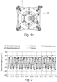
- axial means along the longitudinal axis (in Fig. 1b from bottom to top), “radial” a direction perpendicular to the longitudinal axis and “circumferential” a direction around the longitudinal axis.
- the vibrating disc mill 10 comprises a mill arrangement 12 and a bearing frame that is firmly anchored in the environment, for example on the floor of a factory hall.
- the mill arrangement 12 is spring-mounted on the bearing frame in particular via tension springs 15 and compression springs 17.
- tension springs 15 and compression springs 17 are provided.
- the number of bearing points for the tension and compression springs is preferably the same, but it can also be different.
- the bearing can also be provided with dampers.
- the mill arrangement 12 has a grinding chamber 14 with a filling opening that can be closed with a lid 13 and through which the material to be ground is filled into the grinding chamber 14.
- the grinding elements (not shown), which are also called grinding equipment, are provided in the grinding chamber 14.
- the grinding chamber 14 preferably has a cylindrical cavity with a circular cross-section in which a grinding ring and a grinding cylinder/stone are loosely arranged.
- An acceleration sensor 20 is attached to the mill arrangement 12, which can detect at least the acceleration in the x and y directions (radial directions) and preferably also in the z direction (axial direction).
- the acceleration sensor 20 is preferably attached to the flange 24 or directly to the grinding chamber 14, but can generally be attached anywhere on the mill arrangement 12.
- the tension and compression springs 15, 17 control the horizontal course and prevent the grinding vessel from swinging in the vertical axis.
- the drive motors of vibrating disc mills 10 run at a speed of 300 to a maximum of 1500 rpm.
- the vibration is generated by an eccentric mass.
- the vibrations transmitted to the grinding chamber 14 set the grinding stone and the grinding ring in motion and start different comminution processes within the grinding vessel (see Fig. 3 ). These include the compression of the particle between the grinding chamber wall, grinding ring and/or grinding stone, the shearing of the particle between the wall, ring and/or stone, the impact of the ring and/or stone on the particle, the impact of the particle on the wall and the collision between two particles.
- the acceleration sensor 20 which is attached to the mill arrangement 12, can be used to record the movements of the grinding vessel with sampling rates of 100 Hz or higher.
- the data is output to a higher-level evaluation system with a database via a control module of the mill.
- the changes in the acceleration values recorded during the grinding process provide information about the changes in the material in the grinding chamber 14 caused by the grinding.
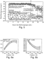
- the acceleration values and their changes can be displayed graphically and statistically evaluated. Extensive experimental investigations have shown that the increase in the grain size fraction in the lower range (e.g. ⁇ 45-70 ⁇ m) brings with it a characteristic change in the grinding vessel acceleration. A pattern that can always be observed is a significant disturbance of the sinusoidal oscillation of the grinding vessel.
- the change in the standard deviation of the root mean square correlates significantly with the change in particle size and can be used as a measure of the grain size distribution in the.
- other parameters such as changes in the acceleration mean values and frequency changes in the Fast Fourier Transformation (FFT) analysis can be used to make additional statements about material changes such as the occurrence of agglomerates. Since the change in the acceleration parameters depends on the type of material to be ground and the type of mill used, it is necessary to prepare calibration curves for different types of material and different types of mills or grinding chambers 14. To calibrate the mill arrangement 12, materials with a known grain size distribution are placed in the grinding chamber 14. The resulting acceleration values can be used to create calibration curves in order to be able to make a prediction about the grain size distribution during the grinding process. For example, in Fig. 6a and 6b Calibration curves (material: clinker) for standard deviation and mean square values of x- and y- acceleration in relation to the proportion of grain size fraction smaller than 45 ⁇ m are shown.
- Fig. 7 is an example of how the grinding time after the transition point U correlates with the change in the grain size fraction.
- the data set used contains two different samples of ferrotitanium (fine material and coarse material). This allows differences in the input grain size to be extrapolated.
- the time at which a vibrating disc mill 10 should be switched off for a specific material to be ground can be reliably determined, or acceleration limit values can be stored in the control system, which then result in the mill being switched off if they are exceeded or undercut. In this way, optimal grain size distributions of the material to be ground can be achieved even without the user personally monitoring the vibrating disc mill 10.
- the acceleration data also form the basis for so-called tool condition monitoring (TCM).
- TCM tool condition monitoring
- the TCM system of this vibrating disc mill 10 is able to use the acceleration data to make statements about the functional state of the horizontal tension springs 15, the vertical compression springs 17, the drive motor 16 and the grinding elements/set in the grinding chamber 14. Monitoring these components is very important because a significant change in their condition affects the grinding efficiency and thus worsens the reproducibility of the grinding results and the grain size distribution. A decrease in the reproducibility of the grinding results has a direct impact on the reproducibility and accuracy of the analysis results.
- the process for creating and maintaining a condition monitoring system is as follows:
- the acceleration data of a trouble-free grinding process under predetermined conditions are recorded and saved using so-called reference runs.
- a trouble-free idle operation i.e. without grinding material
- the characteristic values are recorded for this purpose over a certain period of time at a defined speed. These characteristic values are recorded again at regular intervals in Form so-called test runs with exactly the same parameters and compared with the reference values.
- the vector of x and y acceleration is used to evaluate the condition monitoring. In contrast to the root mean square, this vector has a direction. All vectors of both the reference and the test run together form a more or less uniform circle. This circle is divided into 18 segments with an opening angle of, for example, 20° each for topological diagnosis.
- Fig. 8 A representation of the vector end points from x and y acceleration is shown. This results in a circular distribution of the data points. For each segment, the mean value and the associated deviation of the vectors contained in the segment are calculated for each reference run and test run.
- Figures 9a Average values of the acceleration vectors in the 18 segments are shown, which are derived from the results of 10 reference runs.
- the horizontal tension springs of the oscillating unit play a particularly important role in keeping the oscillating unit in balance and guiding the grinding vessel in as circular a path as possible. Deviation from this path due to the weakening of one or more springs leads to a deviation from this ideal path and an impairment of the grinding result.
- a reduction in the mean values and an increase in the standard deviation Fig. 9b .
- FIG. 9a A comparison of the mean values of the acceleration vectors in the 18 segments is shown, where Fig. 9a the results from 10 reference runs and Fig. 9b 10 consecutive test runs with weakened horizontal tension springs in the left area of the vibration unit. The examination of the value differences between reference and test runs results in a characteristic pattern.
- Fig. 10 the differences in the mean values between reference runs and test runs for mean values (top) and standard deviation (bottom) in the individual segments are shown.
- the typical effects of weakened tension springs are shown with a decrease in the mean values and an increase in the standard deviation in the affected segments.
- the drive motor 16 and in particular its attachment to the flange 24 is also subjected to a relatively high mechanical load due to the free suspension in the bearing frame. This can lead to damage to the anchor bolts between the motor and the eccentric housing and even to tearing off.
- the mill's TCM system can detect such weakenings before they tear off and take the appropriate countermeasures in the form of predictive maintenance. Acceleration values show a local decrease in the corresponding segments when the anchor bolts are weakened. In addition, there is an increasing deformation of the circular acceleration pattern.
- Figure 11 various representations of the vectors (circle) and the mean square (diagram) from the x and y acceleration values before the actual break of the anchoring screws are shown.
- a clear deformation of the vector curve is visible, which enables a diagnosis of an impending break days before the event.
- the break of the anchoring screw itself also shows a characteristic pattern, which can be detected by the system. If the anchoring screw breaks, there is a sudden drop in the acceleration values during a grinding process ( Fig. 12 ).
- the integrity of the shape and the weight of the ring and stone also have a decisive influence on the grinding performance of the vibrating disc mill 10 and on the grinding result.
- the mechanical load causes wear on the grinding set, which leads to a change in shape, especially at the ring and stone phases, and a decrease in weight.
- the grinding set can be monitored using the TCM system. With increasing wear, an increase in the standard deviation is shown in the test runs. In Fig. 13a and 13 b Two test runs with new ( Fig. 13a ) and worn ( Fig. 13b ) grinding set. This deviation is detectable in all segments, in contrast to the local change in the springs. In Fig.
- TCM system other important conditions of the mill can be identified using the TCM system. For example, in the case of particularly sticky and adhesive material, it can be determined whether the grinding vessel has been cleaned sufficiently or whether there is still residual material after cleaning that could potentially lead to contamination of the subsequent sample.
- FFT analysis also opens up possibilities for identifying the formation of agglomerates.
Landscapes
- Engineering & Computer Science (AREA)
- Food Science & Technology (AREA)
- Crushing And Grinding (AREA)
Claims (10)
- Broyeur vibrant à disque (10) pour broyer des échantillons de minéraux, comprenantun agencement de broyage (12) avec une chambre de broyage (14) et un moteur d'entraînement (16) qui est relié de manière fixe en mouvement à la chambre de broyage (14), qui génère une oscillation et la transmet à la chambre de broyage (14) ;un cadre de palier (18) sur lequel l'agencement de broyage (12) est monté sur ressort ;caractérisé en ce queun capteur d'accélération est disposé sur l'agencement de broyage (12), qui détecte l'accélération de l'agencement de broyage dans les directions x et y, les directions x et y étant des directions radiales.
- Broyeur vibrant à disque (10) selon la revendication 1, dans lequel le capteur d'accélération (20) est fixé sur la bride (24) entre le moteur d'entraînement (16) et la chambre de broyage (14).
- Broyeur vibrant à disque selon l'une des revendications précédentes, dans lequel l'agencement de broyage (12) est monté sur au moins trois points d'appui (21, 22), chacun au moyen de ressorts de traction et/ou de compression (15, 17).
- Broyeur vibrant à disque selon la revendication 3, dans lequel un point d'appui comprend respectivement un ressort de compression (17) et/ou deux ressorts de traction (15).
- Procédé de vérification des fonctions d'un broyeur vibrant à disque (10) selon l'une des revendications 1 à 4, comprenant les étapes consistant à :- effectuer une opération de broyage ;- mesurer des accélérations de l'agencement de broyage dans les directions x et y, les directions x et y étant des directions radiales ;- enregistrer les valeurs d'accélération mesurées sous forme de courbe d'accélération.
- Procédé selon la revendication 5, dans lequel l'exécution de l'opération de broyage est effectuée au moins une fois dans des conditions prédéterminées et la courbe d'accélération correspondante est enregistrée comme courbe de référence.
- Procédé selon la revendication 6, dans lequel des opérations de broyage ultérieures sont également effectuées dans les conditions prédéterminées et les courbes d'accélération correspondantes sont comparées à la courbe de référence.
- Procédé selon la revendication 6 ou 7, dans lequel les conditions prédéterminées comprennent une chambre de broyage (14) vide.
- Procédé selon l'une quelconque des revendications 5 à 7, dans lequel les étapes consistant à effectuer une opération de broyage, à mesurer les accélérations et à enregistrer les valeurs d'accélération sont effectuées à chaque opération de broyage.
- Procédé selon l'une quelconque des revendications 5 à 9, dans lequel l'opération de broyage est interrompue au niveau d'une zone prédéterminée de la courbe d'accélération.
Priority Applications (1)
| Application Number | Priority Date | Filing Date | Title |
|---|---|---|---|
| EP19190335.0A EP3772377B1 (fr) | 2019-08-06 | 2019-08-06 | Broyeur vibrant à disque doté de système de capteur |
Applications Claiming Priority (1)
| Application Number | Priority Date | Filing Date | Title |
|---|---|---|---|
| EP19190335.0A EP3772377B1 (fr) | 2019-08-06 | 2019-08-06 | Broyeur vibrant à disque doté de système de capteur |
Publications (3)
| Publication Number | Publication Date |
|---|---|
| EP3772377A1 EP3772377A1 (fr) | 2021-02-10 |
| EP3772377C0 EP3772377C0 (fr) | 2024-11-20 |
| EP3772377B1 true EP3772377B1 (fr) | 2024-11-20 |
Family
ID=67551192
Family Applications (1)
| Application Number | Title | Priority Date | Filing Date |
|---|---|---|---|
| EP19190335.0A Active EP3772377B1 (fr) | 2019-08-06 | 2019-08-06 | Broyeur vibrant à disque doté de système de capteur |
Country Status (1)
| Country | Link |
|---|---|
| EP (1) | EP3772377B1 (fr) |
Families Citing this family (1)
| Publication number | Priority date | Publication date | Assignee | Title |
|---|---|---|---|---|
| DE102023133063A1 (de) * | 2023-11-27 | 2025-05-28 | Nexopart GmbH & Co. KG | Verfahren und Steuereinrichtung zum Betreiben einer Labormühle |
Family Cites Families (3)
| Publication number | Priority date | Publication date | Assignee | Title |
|---|---|---|---|---|
| JPS4330602Y1 (fr) * | 1968-06-29 | 1968-12-13 | ||
| BE791276A (fr) * | 1972-04-15 | 1973-03-01 | Herzog Gottfried | Concasseur oscillant pour broyer, homogeneiser et melanger des solides,produits chimiques et les produits dont ils decoulent |
| DE10123716A1 (de) * | 2001-05-15 | 2002-11-21 | Herzog Maschinenfabrik Gmbh & | Schwingmühle |
-
2019
- 2019-08-06 EP EP19190335.0A patent/EP3772377B1/fr active Active
Also Published As
| Publication number | Publication date |
|---|---|
| EP3772377A1 (fr) | 2021-02-10 |
| EP3772377C0 (fr) | 2024-11-20 |
Similar Documents
| Publication | Publication Date | Title |
|---|---|---|
| EP2924526B1 (fr) | Procédé destiné au réglage et/ou à la surveillance de paramètres de fonctionnement d'une machine d'usinage de pièces | |
| EP3218114B1 (fr) | Procédé de surveillance et/ou de régulation du fonctionnement d'une centrifugeuse | |
| DE69020078T2 (de) | Prüfung von viskoelastischen Stoffen. | |
| DE202008014792U1 (de) | Vorrichtung zum Bewerten von Zerspanungsprozessen | |
| EP2057457A1 (fr) | Rhéomètre | |
| EP3145681A1 (fr) | Procédé permettant d'éviter à un robot de subir des collisions dans une station de travail | |
| DE102019217740B3 (de) | Verfahren und Anordnung zur Überprüfung eines Zustands eines Koordinatenmessgeräts oder eines Drehtisches | |
| EP3493005B1 (fr) | Procédé de détection d'au moins un état d'outil d'un outil de machine à outiller destiné à usiner des pièces et des machines à outiller | |
| EP3144070A1 (fr) | Procede de fonctionnement d'un broyeur tubulaire, agencement destine a determiner des donnees caracteristiques d'un broyeur tubulaire et broyeur tubulaire | |
| DE202011001901U1 (de) | Vorrichtung zur Schwingungsanregung von Rotorblättern im Rahmen von Schwingungstests | |
| EP2405454B1 (fr) | Commutateur de puissance électrique et procédé de fonctionnement d'un commutateur de puissance électrique | |
| EP2653848A1 (fr) | Dispositif de mesure du jeu d'un palier à roulement | |
| EP3772377A1 (fr) | Broyeur vibrant à disque doté de système de capteur | |
| EP3485979A1 (fr) | Procédé de détection de l'état de fonctionnement d'une centrifugeuse | |
| DE19641975C2 (de) | Verfahren und Einrichtung zur automatischen Überwachung von Maschinen, insbesondere für Rotorscheren | |
| DE102007007075A1 (de) | Vorrichtung und Verfahren zur Zerkleinerung von Mahlgut | |
| DE3615963A1 (de) | Verfahren und vorrichtung zum ueberwachen der mahlguthoehe in einer mahlanlage | |
| DE19747628A1 (de) | Verfahren zur Füllstandsüberwachung bei Strahlmühlen und Prallmühlen | |
| DE102011083858A1 (de) | Verfahren und Anordnung zur Überwachung von Zahnrädern im Betrieb | |
| AT519822A2 (de) | Verfahren zum spanenden Bearbeiten eines Werkstückes mittels einem Knickarmroboter | |
| AT517730A1 (de) | Verfahren und Rheometer zur Untersuchung von Pulverproben | |
| DE102016118606A1 (de) | Verfahren zur Ansteuerung eines Elektromotors | |
| EP0748440B1 (fr) | Systeme permettant de surveiller et de reguler la composition de materiaux et d'effectuer une deformation plastique ou ductile du flux de matiere passant dans une machine | |
| DE102008034134A1 (de) | Vorrichtung zum Erzeugen eines Eindrucks | |
| DE102012004846B4 (de) | Verfahren zum Beurteilen der Qualität von Reibpaarungen |
Legal Events
| Date | Code | Title | Description |
|---|---|---|---|
| PUAI | Public reference made under article 153(3) epc to a published international application that has entered the european phase |
Free format text: ORIGINAL CODE: 0009012 |
|
| STAA | Information on the status of an ep patent application or granted ep patent |
Free format text: STATUS: THE APPLICATION HAS BEEN PUBLISHED |
|
| AK | Designated contracting states |
Kind code of ref document: A1 Designated state(s): AL AT BE BG CH CY CZ DE DK EE ES FI FR GB GR HR HU IE IS IT LI LT LU LV MC MK MT NL NO PL PT RO RS SE SI SK SM TR |
|
| AX | Request for extension of the european patent |
Extension state: BA ME |
|
| STAA | Information on the status of an ep patent application or granted ep patent |
Free format text: STATUS: REQUEST FOR EXAMINATION WAS MADE |
|
| 17P | Request for examination filed |
Effective date: 20210625 |
|
| RBV | Designated contracting states (corrected) |
Designated state(s): AL AT BE BG CH CY CZ DE DK EE ES FI FR GB GR HR HU IE IS IT LI LT LU LV MC MK MT NL NO PL PT RO RS SE SI SK SM TR |
|
| GRAP | Despatch of communication of intention to grant a patent |
Free format text: ORIGINAL CODE: EPIDOSNIGR1 |
|
| STAA | Information on the status of an ep patent application or granted ep patent |
Free format text: STATUS: GRANT OF PATENT IS INTENDED |
|
| INTG | Intention to grant announced |
Effective date: 20240704 |
|
| GRAS | Grant fee paid |
Free format text: ORIGINAL CODE: EPIDOSNIGR3 |
|
| GRAA | (expected) grant |
Free format text: ORIGINAL CODE: 0009210 |
|
| STAA | Information on the status of an ep patent application or granted ep patent |
Free format text: STATUS: THE PATENT HAS BEEN GRANTED |
|
| AK | Designated contracting states |
Kind code of ref document: B1 Designated state(s): AL AT BE BG CH CY CZ DE DK EE ES FI FR GB GR HR HU IE IS IT LI LT LU LV MC MK MT NL NO PL PT RO RS SE SI SK SM TR |
|
| REG | Reference to a national code |
Ref country code: GB Ref legal event code: FG4D Free format text: NOT ENGLISH |
|
| REG | Reference to a national code |
Ref country code: CH Ref legal event code: EP |
|
| REG | Reference to a national code |
Ref country code: DE Ref legal event code: R096 Ref document number: 502019012501 Country of ref document: DE |
|
| REG | Reference to a national code |
Ref country code: IE Ref legal event code: FG4D Free format text: LANGUAGE OF EP DOCUMENT: GERMAN |
|
| U01 | Request for unitary effect filed |
Effective date: 20241220 |
|
| U07 | Unitary effect registered |
Designated state(s): AT BE BG DE DK EE FI FR IT LT LU LV MT NL PT RO SE SI Effective date: 20250110 |
|
| PG25 | Lapsed in a contracting state [announced via postgrant information from national office to epo] |
Ref country code: HR Free format text: LAPSE BECAUSE OF FAILURE TO SUBMIT A TRANSLATION OF THE DESCRIPTION OR TO PAY THE FEE WITHIN THE PRESCRIBED TIME-LIMIT Effective date: 20241120 Ref country code: IS Free format text: LAPSE BECAUSE OF FAILURE TO SUBMIT A TRANSLATION OF THE DESCRIPTION OR TO PAY THE FEE WITHIN THE PRESCRIBED TIME-LIMIT Effective date: 20250320 |
|
| PG25 | Lapsed in a contracting state [announced via postgrant information from national office to epo] |
Ref country code: ES Free format text: LAPSE BECAUSE OF FAILURE TO SUBMIT A TRANSLATION OF THE DESCRIPTION OR TO PAY THE FEE WITHIN THE PRESCRIBED TIME-LIMIT Effective date: 20241120 |
|
| PG25 | Lapsed in a contracting state [announced via postgrant information from national office to epo] |
Ref country code: NO Free format text: LAPSE BECAUSE OF FAILURE TO SUBMIT A TRANSLATION OF THE DESCRIPTION OR TO PAY THE FEE WITHIN THE PRESCRIBED TIME-LIMIT Effective date: 20250220 |
|
| PG25 | Lapsed in a contracting state [announced via postgrant information from national office to epo] |
Ref country code: GR Free format text: LAPSE BECAUSE OF FAILURE TO SUBMIT A TRANSLATION OF THE DESCRIPTION OR TO PAY THE FEE WITHIN THE PRESCRIBED TIME-LIMIT Effective date: 20250221 |
|
| PG25 | Lapsed in a contracting state [announced via postgrant information from national office to epo] |
Ref country code: PL Free format text: LAPSE BECAUSE OF FAILURE TO SUBMIT A TRANSLATION OF THE DESCRIPTION OR TO PAY THE FEE WITHIN THE PRESCRIBED TIME-LIMIT Effective date: 20241120 |
|
| PG25 | Lapsed in a contracting state [announced via postgrant information from national office to epo] |
Ref country code: RS Free format text: LAPSE BECAUSE OF FAILURE TO SUBMIT A TRANSLATION OF THE DESCRIPTION OR TO PAY THE FEE WITHIN THE PRESCRIBED TIME-LIMIT Effective date: 20250220 |
|
| PG25 | Lapsed in a contracting state [announced via postgrant information from national office to epo] |
Ref country code: SM Free format text: LAPSE BECAUSE OF FAILURE TO SUBMIT A TRANSLATION OF THE DESCRIPTION OR TO PAY THE FEE WITHIN THE PRESCRIBED TIME-LIMIT Effective date: 20241120 |
|
| PG25 | Lapsed in a contracting state [announced via postgrant information from national office to epo] |
Ref country code: SK Free format text: LAPSE BECAUSE OF FAILURE TO SUBMIT A TRANSLATION OF THE DESCRIPTION OR TO PAY THE FEE WITHIN THE PRESCRIBED TIME-LIMIT Effective date: 20241120 |
|
| PG25 | Lapsed in a contracting state [announced via postgrant information from national office to epo] |
Ref country code: CZ Free format text: LAPSE BECAUSE OF FAILURE TO SUBMIT A TRANSLATION OF THE DESCRIPTION OR TO PAY THE FEE WITHIN THE PRESCRIBED TIME-LIMIT Effective date: 20241120 |
|
| PLBE | No opposition filed within time limit |
Free format text: ORIGINAL CODE: 0009261 |
|
| STAA | Information on the status of an ep patent application or granted ep patent |
Free format text: STATUS: NO OPPOSITION FILED WITHIN TIME LIMIT |
|
| U20 | Renewal fee for the european patent with unitary effect paid |
Year of fee payment: 7 Effective date: 20250826 |
|
| 26N | No opposition filed |
Effective date: 20250821 |
|
| REG | Reference to a national code |
Ref country code: CH Ref legal event code: H13 Free format text: ST27 STATUS EVENT CODE: U-0-0-H10-H13 (AS PROVIDED BY THE NATIONAL OFFICE) Effective date: 20260324 |
|
| PG25 | Lapsed in a contracting state [announced via postgrant information from national office to epo] |
Ref country code: MC Free format text: LAPSE BECAUSE OF FAILURE TO SUBMIT A TRANSLATION OF THE DESCRIPTION OR TO PAY THE FEE WITHIN THE PRESCRIBED TIME-LIMIT Effective date: 20241120 |
|
| PG25 | Lapsed in a contracting state [announced via postgrant information from national office to epo] |
Ref country code: CH Free format text: LAPSE BECAUSE OF NON-PAYMENT OF DUE FEES Effective date: 20250831 |
|
| GBPC | Gb: european patent ceased through non-payment of renewal fee |
Effective date: 20250806 |