EP3772620A1 - Système de traitement de l'air permettant d'améliorer une qualité de l'air d'un air intérieur dans une pièce et son procédé de fonctionnement - Google Patents
Système de traitement de l'air permettant d'améliorer une qualité de l'air d'un air intérieur dans une pièce et son procédé de fonctionnement Download PDFInfo
- Publication number
- EP3772620A1 EP3772620A1 EP20184234.1A EP20184234A EP3772620A1 EP 3772620 A1 EP3772620 A1 EP 3772620A1 EP 20184234 A EP20184234 A EP 20184234A EP 3772620 A1 EP3772620 A1 EP 3772620A1
- Authority
- EP
- European Patent Office
- Prior art keywords
- air
- operating state
- treatment device
- air treatment
- indoor
- Prior art date
- Legal status (The legal status is an assumption and is not a legal conclusion. Google has not performed a legal analysis and makes no representation as to the accuracy of the status listed.)
- Granted
Links
Images


Classifications
-
- F—MECHANICAL ENGINEERING; LIGHTING; HEATING; WEAPONS; BLASTING
- F24—HEATING; RANGES; VENTILATING
- F24C—DOMESTIC STOVES OR RANGES ; DETAILS OF DOMESTIC STOVES OR RANGES, OF GENERAL APPLICATION
- F24C15/00—Details
- F24C15/20—Removing cooking fumes
- F24C15/2021—Arrangement or mounting of control or safety systems
-
- F—MECHANICAL ENGINEERING; LIGHTING; HEATING; WEAPONS; BLASTING
- F24—HEATING; RANGES; VENTILATING
- F24F—AIR-CONDITIONING; AIR-HUMIDIFICATION; VENTILATION; USE OF AIR CURRENTS FOR SCREENING
- F24F8/00—Treatment, e.g. purification, of air supplied to human living or working spaces otherwise than by heating, cooling, humidifying or drying
- F24F8/10—Treatment, e.g. purification, of air supplied to human living or working spaces otherwise than by heating, cooling, humidifying or drying by separation, e.g. by filtering
- F24F8/108—Treatment, e.g. purification, of air supplied to human living or working spaces otherwise than by heating, cooling, humidifying or drying by separation, e.g. by filtering using dry filter elements
-
- F—MECHANICAL ENGINEERING; LIGHTING; HEATING; WEAPONS; BLASTING
- F24—HEATING; RANGES; VENTILATING
- F24F—AIR-CONDITIONING; AIR-HUMIDIFICATION; VENTILATION; USE OF AIR CURRENTS FOR SCREENING
- F24F8/00—Treatment, e.g. purification, of air supplied to human living or working spaces otherwise than by heating, cooling, humidifying or drying
- F24F8/10—Treatment, e.g. purification, of air supplied to human living or working spaces otherwise than by heating, cooling, humidifying or drying by separation, e.g. by filtering
- F24F8/15—Treatment, e.g. purification, of air supplied to human living or working spaces otherwise than by heating, cooling, humidifying or drying by separation, e.g. by filtering by chemical means
- F24F8/158—Treatment, e.g. purification, of air supplied to human living or working spaces otherwise than by heating, cooling, humidifying or drying by separation, e.g. by filtering by chemical means using active carbon
-
- F—MECHANICAL ENGINEERING; LIGHTING; HEATING; WEAPONS; BLASTING
- F24—HEATING; RANGES; VENTILATING
- F24F—AIR-CONDITIONING; AIR-HUMIDIFICATION; VENTILATION; USE OF AIR CURRENTS FOR SCREENING
- F24F2110/00—Control inputs relating to air properties
- F24F2110/50—Air quality properties
-
- F—MECHANICAL ENGINEERING; LIGHTING; HEATING; WEAPONS; BLASTING
- F24—HEATING; RANGES; VENTILATING
- F24F—AIR-CONDITIONING; AIR-HUMIDIFICATION; VENTILATION; USE OF AIR CURRENTS FOR SCREENING
- F24F2110/00—Control inputs relating to air properties
- F24F2110/50—Air quality properties
- F24F2110/52—Air quality properties of the outside air
-
- Y—GENERAL TAGGING OF NEW TECHNOLOGICAL DEVELOPMENTS; GENERAL TAGGING OF CROSS-SECTIONAL TECHNOLOGIES SPANNING OVER SEVERAL SECTIONS OF THE IPC; TECHNICAL SUBJECTS COVERED BY FORMER USPC CROSS-REFERENCE ART COLLECTIONS [XRACs] AND DIGESTS
- Y02—TECHNOLOGIES OR APPLICATIONS FOR MITIGATION OR ADAPTATION AGAINST CLIMATE CHANGE
- Y02B—CLIMATE CHANGE MITIGATION TECHNOLOGIES RELATED TO BUILDINGS, e.g. HOUSING, HOUSE APPLIANCES OR RELATED END-USER APPLICATIONS
- Y02B30/00—Energy efficient heating, ventilation or air conditioning [HVAC]
- Y02B30/70—Efficient control or regulation technologies, e.g. for control of refrigerant flow, motor or heating
Definitions
- Air treatment system for improving an air quality of indoor air in a room and method for its operation
- the invention relates to an air treatment system for improving an air quality of indoor air in a room and a method for its operation.
- the invention is based on the object of creating an air treatment system for improving the air quality of the indoor air and a method for its operation.
- the advantage that can be achieved with the invention is in particular that the air treatment system and the method for its operation are improved.
- the design of the air treatment system according to the invention and the method for its operation it is possible, for example, to use a single air treatment device both for a general improvement in the air quality of the indoor air in the room and for an improvement in the air quality of the indoor air in the room tailored to specific household appliances .
- the costs and the space required for them are correspondingly reduced. This is particularly advantageous in the case of cooking, dining and living rooms that merge into one another or are connected to one another.
- the air treatment device can be freely selected within wide suitable limits in terms of type, mode of operation, dimensioning, material and arrangement.
- An advantageous development of the air treatment system according to the invention provides that the air treatment device is designed and set up for a circulating air mode, an exhaust air mode and an air cleaning mode. In this way, an adapted and optimized improvement of the air quality of the indoor air in the room is made possible depending on the requirements of the individual case.
- the air treatment device has a grease filter and / or an activated carbon filter and / or a plasma unit and / or a HEPA filter.
- the air treatment device can be used in a large number of scenarios that are different from one another and that are conceivable for the indoor air of a room.
- the air treatment device is able to provide an exhaust air function and / or a circulating air function and / or an air cleaning function.
- the exhaust air function the pumped air is drawn out of the building.
- the exhaust air function is used in an exhaust air operating state, but can also be used in the long-term operating state.
- the air circulation function the conveyed air is circulated in the room where the air treatment device is installed.
- the air is preferably passed at least over a grease filter.
- the air circulation function is used in an exhaust air operating mode, but can also be used in long-term operating mode.
- the conveyed air is circulated in the installation room of the air treatment device, the air being passed through additional filters such as an activated carbon filter and / or a plasma unit and / or a HEPA filter.
- the air cleaning function is used in a cleaning operation and is preferably used in long-term operation.
- a particularly advantageous development of the air treatment system according to the invention provides that the air treatment device is designed as an extractor hood for a hob. In this way, the air treatment device and thus the air treatment system according to the invention as a whole can be integrated into the room in a visually pleasing and space-saving manner.
- An air treatment system designed as a fume hood can be designed both as a fume extractor hood arranged above a hob and as a fume extractor device that is integrated in a hob and sucks off below the hob.
- Such an air treatment system combines the function of an air cleaner with the conventional function of an extractor hood for a cooktop, whereby an extractor hood already has the main components, such as fan, grease filter, activated carbon filter.
- the air treatment system has an output unit connected to the control in a signal-transmitting manner for outputting acoustic and / or visual information to a user of the air treatment system. This enables information and recommendations for action that are related to the air treatment system and / or the improvement of the air quality of the indoor air to be output to the user.
- a ventilation instruction is output by means of the output unit as a function of the air quality of the inside air, the air quality of the outside air and the operating state of the household appliance.
- a ventilation notice is in particular a notice to the user to open a window manually.
- a ventilation notice can also be a notice to a house control, for example that it is opening a window or an air inlet flap.
- a further advantageous development of the method according to the invention provides that the air quality of the indoor air and / or the air quality of the outdoor air comprises at least one variable from fine dust, volatile organic compounds, temperature and relative humidity.
- the detection of the air quality and thus the operation of the air treatment system according to the invention is made possible for a multitude of scenarios that differ from one another, depending on the requirements of the individual case.
- an advantageous further development of the aforementioned embodiment of the method according to the invention provides that the air treatment device is automatically switched to the exhaust air operating state or either the circulating air operating state or the air cleaning operation depending on a temperature difference between the temperature of the outside air and the temperature of the inside air. Accordingly, it is possible not to operate the air treatment device in the exhaust air mode, for example, when there is a large difference between the temperature of the inside air on the one hand and the temperature of the outside air on the other hand, but instead to operate it in the air recirculation mode or in the air cleaning mode. This makes it possible to save energy, since, for example, when the outside temperature is very low in winter, there is no warm inside air from the room into the open environment is discharged. The same applies, for example, to very high outside temperatures in summer when the room and thus the inside air are cooled.
- the exhaust air operating state and recirculating air operating state are two control modes in which the air treatment device works with higher power than in the air cleaning mode.
- the control modes are usually carried out in connection with a cooking event in the immediate vicinity of the air handling device.
- Another control mode is the air cleaning operation, which can take place separately from a cooking event.
- the speed of the fan of the air handling unit - depending on the fan level and unit type selected - is in a range between 500 revolutions per minute and 3000 revolutions per minute. This usually results in a sound level of more than 35 dB (A), in particular - depending on the selected fan level and device type - in a range between 36 dB (A) and 64 dB (A).
- the air treatment device comprises a long-term operating state.
- the air treatment device in particular the fan of the air treatment device, is operated in such a way that the sound level is less than 30 dB (A). This is achieved, for example, by setting the speed of the fan to less than 400 revolutions per minute, preferably in a range between 320 revolutions per minute and 180 revolutions per minute.
- the air treatment device can essentially be perceived as not in operation during the long-term operating state. This makes it possible, for example, to use the air treatment device Operate over a long period of time without the people in the room or house being disturbed by the operation of the air handling unit.
- One aspect of the invention is that, in the long-term operating state, an air flow rate of less than 150 cubic meters per hour, preferably in a range of 110 cubic meters per hour and 50 cubic meters per hour, is set.
- An advantageous development of the aforementioned embodiment of the method according to the invention provides that the long-term operating state of the air treatment device as a function of a previously determined period of time of operation of the domestic appliance and / or a previously determined operating temperature of the domestic appliance and / or a previously determined operating mode of the domestic appliance and / or a previously defined automatic program of the household appliance and / or the air quality of the indoor air is started automatically. In this way, the comfort of use is increased while the air quality of the indoor air in the room is improved at the same time.
- An advantageous further development of the two last-mentioned embodiments of the method according to the invention provides that the long-term operating state of the air treatment device is automatically dependent on a predetermined period of time and / or a manual and / or automatic switchover of the air treatment device to another operating state of the air treatment device and / or the air quality of the indoor air is terminated. This ensures that the air treatment device is operated in the long-term operating state only as required and / or that another operating state of the air treatment device can be switched on manually or automatically in the desired manner.
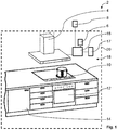
- the air treatment system 2 comprises an air treatment device 4 designed as an extractor hood for treating the inside air, not shown, an inside air sensor unit 6 for determining the air quality of the inside air, an outside air sensor unit 8 for determining the air quality of the outside air, not shown, three household appliances 10, 12, 14 positioned in the room and a controller 16 for the automatic control of the air treatment device 4 depending on the air quality of the inside air, the air quality of the outside air and an operating state of the household appliances 10, 12, 14, the controller 16 with the inside air sensor unit 6, with the outside air sensor unit 8 and with the household appliances 10 , 12, 14 is connected to transmit signals.
- the term "outside air sensor unit” should be interpreted broadly and encompasses all conceivable ways of determining data on the air quality of the outside air. For example, it is conceivable that this data is obtained from Internet services using an Internet connection.
- the room 18 is in the Fig. 1 delimited by a dashed line 20 from the free environment.
- the household appliances 10, 12, 14 are a hob 10, an oven with steam cooking function and pyrolysis function 12 and a dishwasher 14.
- the air treatment device 4 is assigned in particular to the hob 10, namely arranged above the hob 10.
- the air treatment system 2 has an output unit 17, which is connected to the controller 16 in a signal-transmitting manner, for outputting acoustic and / or visual information to a user of the air treatment system 2.
- the air treatment device 4 is in the Fig. 2 shown roughly schematically and comprises a grease filter 22, a blower 24, a plasma unit 26, an activated carbon filter 28, a HEPA filter 30 and has a flow channel 32 for the exhaust air mode, a flow channel 34 for the air cleaning mode and a flow channel 36 for the air circulation mode of the air treatment device 4 on.
- the air treatment device 4 is thus designed and set up for the operating states of circulating air mode, exhaust air mode and air cleaning mode.
- the inside air from the room 18 is only passed over the grease filter 22 in the exhaust air operating state of the air treatment device 4.
- the interior air is guided from the room 18 via the grease filter 22, the plasma unit 26 and the activated carbon filter 28. If the air treatment device 4 is operated in its air purification mode, the inside air from the room 18 is guided via the grease filter 22, the plasma unit 26, the activated carbon filter 28 and the HEPA filter 30.
- the air treatment device 4 of the air treatment system 2 is initially switched off.
- the indoor air sensor unit 6 and the controller 16 are used to determine and evaluate the air quality of the indoor air in the room 18 at predetermined time intervals or continuously. For this purpose, the parameters fine dust, volatile organic compounds, temperature and relative humidity are determined and evaluated in a manner known to the person skilled in the art.
- the parameters fine dust, volatile organic compounds, temperature and relative humidity of the outside air are determined and evaluated by means of the outside air sensor unit 8 and the controller 16 in a manner known to those skilled in the art.
- the respective operating state of the household appliances 10, 12, 14 is determined in a manner known to the person skilled in the art and evaluated in the controller 16.
- the temperature of the inside air in the present exemplary embodiment is specified in advance as a preset value and stored in the controller 16.
- the default value for the temperature of the interior air is entered into the air treatment system 2 by a user (not shown) by means of a user interface (not shown).
- the default value can be selected, for example, in a value range from 15 ° C to 22 ° C.
- a higher temperature difference between the default value for the temperature of the inside air and the temperature of the outside air leads to the fact that the air treatment device 4 is not operated in the exhaust air mode, but either in the recirculation mode or in the air cleaning mode. This is done in order to save energy for cooling or heating the room 18 in the event of extreme temperature differences.
- the symbol “+” stands for good air quality and the symbol “-” for poor air quality.
- the relative humidity is shown separately in the table, with the symbol “+” standing for a tolerable relative humidity and the symbol “-” for too high humidity.
- the operating states of the hob 10 are indicated in the table with “1” for hob 10 switched on and with “0” for hob 10 switched off. The same applies to the "steam cooking” and “pyrolysis” operating states of the oven 12 and to the "auto-open" operating state of the dishwasher 14. No field entry means that the value for this variable is irrelevant for the control of the air treatment device 4.
- the controller 16 of the air treatment system 2 determines that a cooking process is currently taking place on the hob 10.
- the air treatment device 4 would in this case be operated either in the exhaust air operating state or in the recirculating air operating state in order to clean the inside air from cooking vapors (not shown). If the temperature difference is too great, marked with “Y” in the table, the air treatment device 4 is operated in the circulating air operating state. Otherwise, if the temperature difference is not too great, marked with "X" in the table, the air treatment device 4 is operated in the exhaust air operating state.
- the operating states of the air treatment device 4 are shown in the table as follows: "A” for exhaust air mode, "U” for air recirculation mode, "L” for air cleaning mode and "0" for the case that the air treatment device 4 is not operated, i.e. the fan 24 of the air treatment device 4 is switched off. "V” stands for the output of a ventilation suggestion by means of the output unit 17 to the user.
- the air treatment device 4 is operated in the air cleaning mode if the indoor air quality is poor, and is marked with "-" in the table.
- the air treatment device 4 is also operated in the air cleaning mode if the indoor air and the outdoor air are poor in air quality, marked "-" in the table.
- the air treatment device 4 is output to the user by means of the output unit 17 if the indoor air quality is poor and the outdoor air is good.
- the dishwasher 14 has an operating state in which the dishwasher 14 is automatically opened during a drying process. Accordingly, moist air escapes from the dishwasher 14 into the room 18. If an increased relative humidity is detected in the room 18 by means of the indoor air sensor unit 6, the air treatment device 4 is operated in the exhaust air operating state. This effectively removes the moisture from the space 18, so that undesired mold formation is effectively prevented. The same applies to the case if the oven 12 is operated in its steam cooking function.
- the air treatment device 4 is operated in the exhaust air operating state. Otherwise, if the temperature difference is too great, the air treatment device 4 is operated in the air cleaning mode. This effectively removes undesirable odors and pollutants from the interior air of the room 18 after the pyrolysis.
- the air treatment device 4 of the air treatment system 2 includes, in addition to the above-mentioned and explained operating states, also a long-term operating state, the air handling device 4 being operated in the long-term operating state in such a way that the air handling device 4 is operated during the long-term operating state by the user and generally by himself in the room 18 or in the Household people are essentially noticeable as not being in operation.
- the fan 24 of the air treatment device 4 is operated, for example, at a speed which is lower than the lowest speed in normal operation.
- the fan 24 is preferably operated at a very low speed, in particular less than 110 revolutions per minute, so that the noise emission is minimized to a sound level of less than 32 dB (A).
- the air treatment device 4 can have suitable sound insulation in a manner known to the person skilled in the art.
- the long-term operating state is an operating state which is also carried out in the exhaust air function or circulating air function and / or, like the air cleaning operation, at a separate time from a cooking process.
- the fan 24 is only operated at a reduced speed, in particular less than 330 revolutions per minute and / or a reduced air flow rate of less than 110 cubic meters per hour.
- the air treatment device 4 is automatically transferred to its long-term operating state by means of the controller 16 if the hob 10 is switched on for longer than a predetermined period of time, preferably longer than 10 minutes.
- the long-term operating mode can also be switched on automatically when the Oven 12 is operated above a predetermined temperature, preferably above 150 ° C., or with a predetermined automatic program.
- An automatic transfer of the air treatment device 4 to its long-term operating state is also conceivable if the indoor air sensor unit 6 or another sensor unit networked with the indoor air sensor unit 6 detects an undesired odor or an undesired air quality of the indoor air.
- the detecting indoor air sensor unit 6 is arranged in a flow path of the air treatment device 4, provision can be made for the fan 24 to be switched on briefly, for example at predetermined time intervals, in order to draw indoor air from the room 18 past the indoor air sensor unit 6.
- the long-term operating state of the air treatment device 4 is automatically terminated as a function of a predetermined period of time and / or a manual and / or automatic switchover of the air treatment device 4 to another operating state of the air treatment device 4 and / or the air quality of the indoor air and / or the air quality of the outdoor air.
- the long-term operating state is terminated when the air-handling device 4 has been operated in the long-term operation for a period of more than 24 hours. It is also conceivable that the long-term operating state is automatically terminated when another operating state of the air treatment device 4 has been set manually or automatically on the air treatment system 2.
- the long-term operating state of the air treatment device 4 can be terminated when the above-mentioned undesired odor can no longer be detected by means of the indoor air sensor unit 6 or another sensor unit networked with the indoor air sensor unit 6.
Landscapes
- Engineering & Computer Science (AREA)
- Chemical & Material Sciences (AREA)
- Combustion & Propulsion (AREA)
- Mechanical Engineering (AREA)
- General Engineering & Computer Science (AREA)
- Chemical Kinetics & Catalysis (AREA)
- General Chemical & Material Sciences (AREA)
- Ventilation (AREA)
- Air Conditioning Control Device (AREA)
Applications Claiming Priority (1)
| Application Number | Priority Date | Filing Date | Title |
|---|---|---|---|
| DE102019121115.8A DE102019121115A1 (de) | 2019-08-05 | 2019-08-05 | Luftbehandlungssystem zur Verbesserung einer Luftqualität einer Innenluft in einem Raum und Verfahren zu dessen Betrieb |
Publications (3)
| Publication Number | Publication Date |
|---|---|
| EP3772620A1 true EP3772620A1 (fr) | 2021-02-10 |
| EP3772620C0 EP3772620C0 (fr) | 2025-09-17 |
| EP3772620B1 EP3772620B1 (fr) | 2025-09-17 |
Family
ID=71515072
Family Applications (1)
| Application Number | Title | Priority Date | Filing Date |
|---|---|---|---|
| EP20184234.1A Active EP3772620B1 (fr) | 2019-08-05 | 2020-07-06 | Système de traitement de l'air permettant d'améliorer une qualité de l'air d'un air intérieur dans une pièce et son procédé de fonctionnement |
Country Status (4)
| Country | Link |
|---|---|
| EP (1) | EP3772620B1 (fr) |
| DE (1) | DE102019121115A1 (fr) |
| ES (1) | ES3049788T3 (fr) |
| PL (1) | PL3772620T3 (fr) |
Cited By (3)
| Publication number | Priority date | Publication date | Assignee | Title |
|---|---|---|---|---|
| EP4083513A1 (fr) * | 2021-04-26 | 2022-11-02 | Miele & Cie. KG | Système comprenant un dispositif de cuisson avec un four de cuisson et une hotte d'aspiration, et procéde de fonctionnement du système |
| CN115875703A (zh) * | 2021-09-29 | 2023-03-31 | 佛山市顺德区美的洗涤电器制造有限公司 | 厨房电器的控制方法、厨房电器以及存储介质 |
| DE102021132344A1 (de) | 2021-12-08 | 2023-06-15 | Naber Holding Gmbh & Co. Kg | Verfahren zum Schalten einer Lüftungseinheit, und eine entsprechende Lüftungseinheit |
Citations (8)
| Publication number | Priority date | Publication date | Assignee | Title |
|---|---|---|---|---|
| DE102011082928A1 (de) | 2011-09-19 | 2013-03-21 | BSH Bosch und Siemens Hausgeräte GmbH | Dunstabzugssystem und Verfahren zum Betreiben eines Dunstabzugssystems |
| CN107036140A (zh) * | 2017-05-06 | 2017-08-11 | 广东万家乐燃气具有限公司 | 一种吸油烟机风量的控制方法及用户可自行设置风量的吸油烟机 |
| WO2018061147A1 (fr) * | 2016-09-29 | 2018-04-05 | 三菱電機株式会社 | Système de ventilation |
| CN108240692A (zh) * | 2016-12-23 | 2018-07-03 | 宁波方太厨具有限公司 | 一种厨房新风系统 |
| JP2018105568A (ja) * | 2016-12-27 | 2018-07-05 | 富士工業株式会社 | レンジフード |
| US20180372330A1 (en) * | 2015-07-06 | 2018-12-27 | Koninklijke Philips N.V. | Air processing system and method |
| EP3499133A1 (fr) * | 2017-12-14 | 2019-06-19 | BSH Hausgeräte GmbH | Procédé et dispositif de commande de purification d'air d'une hotte aspirante et hotte aspirante |
| DE102018201047A1 (de) | 2018-01-24 | 2019-07-25 | BSH Hausgeräte GmbH | Verfahren zum Betrieb mindestens einer Funktion eines Haushaltsgerätes und Steuervorrichtung |
-
2019
- 2019-08-05 DE DE102019121115.8A patent/DE102019121115A1/de not_active Ceased
-
2020
- 2020-07-06 PL PL20184234.1T patent/PL3772620T3/pl unknown
- 2020-07-06 EP EP20184234.1A patent/EP3772620B1/fr active Active
- 2020-07-06 ES ES20184234T patent/ES3049788T3/es active Active
Patent Citations (8)
| Publication number | Priority date | Publication date | Assignee | Title |
|---|---|---|---|---|
| DE102011082928A1 (de) | 2011-09-19 | 2013-03-21 | BSH Bosch und Siemens Hausgeräte GmbH | Dunstabzugssystem und Verfahren zum Betreiben eines Dunstabzugssystems |
| US20180372330A1 (en) * | 2015-07-06 | 2018-12-27 | Koninklijke Philips N.V. | Air processing system and method |
| WO2018061147A1 (fr) * | 2016-09-29 | 2018-04-05 | 三菱電機株式会社 | Système de ventilation |
| CN108240692A (zh) * | 2016-12-23 | 2018-07-03 | 宁波方太厨具有限公司 | 一种厨房新风系统 |
| JP2018105568A (ja) * | 2016-12-27 | 2018-07-05 | 富士工業株式会社 | レンジフード |
| CN107036140A (zh) * | 2017-05-06 | 2017-08-11 | 广东万家乐燃气具有限公司 | 一种吸油烟机风量的控制方法及用户可自行设置风量的吸油烟机 |
| EP3499133A1 (fr) * | 2017-12-14 | 2019-06-19 | BSH Hausgeräte GmbH | Procédé et dispositif de commande de purification d'air d'une hotte aspirante et hotte aspirante |
| DE102018201047A1 (de) | 2018-01-24 | 2019-07-25 | BSH Hausgeräte GmbH | Verfahren zum Betrieb mindestens einer Funktion eines Haushaltsgerätes und Steuervorrichtung |
Cited By (4)
| Publication number | Priority date | Publication date | Assignee | Title |
|---|---|---|---|---|
| EP4083513A1 (fr) * | 2021-04-26 | 2022-11-02 | Miele & Cie. KG | Système comprenant un dispositif de cuisson avec un four de cuisson et une hotte d'aspiration, et procéde de fonctionnement du système |
| CN115875703A (zh) * | 2021-09-29 | 2023-03-31 | 佛山市顺德区美的洗涤电器制造有限公司 | 厨房电器的控制方法、厨房电器以及存储介质 |
| DE102021132344A1 (de) | 2021-12-08 | 2023-06-15 | Naber Holding Gmbh & Co. Kg | Verfahren zum Schalten einer Lüftungseinheit, und eine entsprechende Lüftungseinheit |
| DE102021132344B4 (de) | 2021-12-08 | 2024-09-26 | Naber Holding Gmbh & Co. Kg | Verfahren zum Schalten einer Lüftungseinheit und eine entsprechende Lüftungseinheit |
Also Published As
| Publication number | Publication date |
|---|---|
| DE102019121115A1 (de) | 2021-02-11 |
| ES3049788T3 (en) | 2025-12-18 |
| EP3772620C0 (fr) | 2025-09-17 |
| EP3772620B1 (fr) | 2025-09-17 |
| PL3772620T3 (pl) | 2026-01-19 |
Similar Documents
| Publication | Publication Date | Title |
|---|---|---|
| EP3772620B1 (fr) | Système de traitement de l'air permettant d'améliorer une qualité de l'air d'un air intérieur dans une pièce et son procédé de fonctionnement | |
| EP2256418B1 (fr) | Procédé pour régler de la vitesse moyenne de l'air en aval de l'ouverture d'air d'échappement d'un boîtier d'évacuation d'air d'un aspirateur de fumées | |
| EP1800065A1 (fr) | Procede de commande d'un processus de cuisson dans un appareil de cuisson | |
| DE102011082926A1 (de) | Dunstabzugsvorrichtung und Verfahren zum Betreiben einer Dunstabzugsvorrichtung | |
| EP2642213B1 (fr) | Procédé de commande d'un système de ventilation d'au moins une pièce et système de ventilation correspondant | |
| DE10307247A1 (de) | Einrichtung zum Absaugen von Abluft eines Elektrowärmegeräts und Verfahren zum Betrieb derselben | |
| DE102010006455B4 (de) | Verfahren, Steuereinrichtung und -system zur Be-und Entlüftung eines Gesamtraums mit mehreren Teilräumen, insbesondere eines eine Wohneinheit bildenden Gesamtraums | |
| EP1055883B1 (fr) | Hotte aspiratrice de buée | |
| EP2210048B1 (fr) | Dispositif d'aspiration de vapeurs | |
| DE102005024631A1 (de) | Dunstabzugsvorrichtung | |
| DE102021110574B4 (de) | System, umfassend ein Gargerät mit einem Garraum und eine Dunstabzugsvorrichtung, und Verfahren zum Betrieb eines Systems | |
| EP2280226A2 (fr) | Procédé de fonctionnement d'un four de cuisson et four de cuisson | |
| EP3489585A1 (fr) | Dispositif formant hotte aspirante et son procédé de fonctionnement | |
| DE10137820A1 (de) | Dunstabzugshaube mit einem Abluftschacht | |
| DE102015116863B4 (de) | Im Abluft- und Umluftbetrieb zu betreibende Dunstabzugshaube | |
| EP4354024A1 (fr) | Procédé de commande d'un dispositif d'évacuation de vapeurs de cuisson, en particulier pour commander une hotte de cuisson, dispositif de commande, dispositif de cuisson et système de table de cuisson | |
| DE4333195A1 (de) | Gerät zur Be- oder Entlüftung eines Innenraumes | |
| EP4490439A1 (fr) | Procédé de commande d'un dispositif d'extraction de fumées | |
| DE102015109053A1 (de) | Kochfeldeinrichtung und Verfahren zum Betreiben | |
| WO1995009330A1 (fr) | Dispositif d'evacuation d'air | |
| DE102018203165A1 (de) | Dunstabzugsvorrichtung und Verfahren zum Betreiben einer Dunstabzugsvorrichtung | |
| DE102010044215A1 (de) | Verfahren zum Betreiben eines Hausgeräts zum Zubereiten von Lebensmitteln sowie ein derartiges Hausgerät | |
| WO2025132193A1 (fr) | Procédé et programme d'ordinateur pour l'ajustement de la commande d'un dispositif d'extraction de vapeur et dispositif d'extraction de vapeur | |
| DE19953226A1 (de) | Haushaltsbackofen mit Räucherfunktion | |
| DE102022131181A1 (de) | System zur Lüftung eines Raumes |
Legal Events
| Date | Code | Title | Description |
|---|---|---|---|
| PUAI | Public reference made under article 153(3) epc to a published international application that has entered the european phase |
Free format text: ORIGINAL CODE: 0009012 |
|
| STAA | Information on the status of an ep patent application or granted ep patent |
Free format text: STATUS: THE APPLICATION HAS BEEN PUBLISHED |
|
| AK | Designated contracting states |
Kind code of ref document: A1 Designated state(s): AL AT BE BG CH CY CZ DE DK EE ES FI FR GB GR HR HU IE IS IT LI LT LU LV MC MK MT NL NO PL PT RO RS SE SI SK SM TR |
|
| AX | Request for extension of the european patent |
Extension state: BA ME |
|
| STAA | Information on the status of an ep patent application or granted ep patent |
Free format text: STATUS: REQUEST FOR EXAMINATION WAS MADE |
|
| 17P | Request for examination filed |
Effective date: 20210810 |
|
| RBV | Designated contracting states (corrected) |
Designated state(s): AL AT BE BG CH CY CZ DE DK EE ES FI FR GB GR HR HU IE IS IT LI LT LU LV MC MK MT NL NO PL PT RO RS SE SI SK SM TR |
|
| STAA | Information on the status of an ep patent application or granted ep patent |
Free format text: STATUS: EXAMINATION IS IN PROGRESS |
|
| 17Q | First examination report despatched |
Effective date: 20240612 |
|
| GRAP | Despatch of communication of intention to grant a patent |
Free format text: ORIGINAL CODE: EPIDOSNIGR1 |
|
| STAA | Information on the status of an ep patent application or granted ep patent |
Free format text: STATUS: GRANT OF PATENT IS INTENDED |
|
| RIC1 | Information provided on ipc code assigned before grant |
Ipc: F24F 110/52 20180101ALN20250509BHEP Ipc: F24F 110/50 20180101ALI20250509BHEP Ipc: F24F 8/108 20210101ALI20250509BHEP Ipc: F24F 8/158 20210101ALI20250509BHEP Ipc: F24F 8/10 20210101ALI20250509BHEP Ipc: F24C 15/20 20060101AFI20250509BHEP |
|
| INTG | Intention to grant announced |
Effective date: 20250603 |
|
| GRAS | Grant fee paid |
Free format text: ORIGINAL CODE: EPIDOSNIGR3 |
|
| GRAA | (expected) grant |
Free format text: ORIGINAL CODE: 0009210 |
|
| STAA | Information on the status of an ep patent application or granted ep patent |
Free format text: STATUS: THE PATENT HAS BEEN GRANTED |
|
| AK | Designated contracting states |
Kind code of ref document: B1 Designated state(s): AL AT BE BG CH CY CZ DE DK EE ES FI FR GB GR HR HU IE IS IT LI LT LU LV MC MK MT NL NO PL PT RO RS SE SI SK SM TR |
|
| REG | Reference to a national code |
Ref country code: GB Ref legal event code: FG4D Free format text: NOT ENGLISH |
|
| REG | Reference to a national code |
Ref country code: CH Ref legal event code: EP |
|
| REG | Reference to a national code |
Ref country code: IE Ref legal event code: FG4D Free format text: LANGUAGE OF EP DOCUMENT: GERMAN |
|
| REG | Reference to a national code |
Ref country code: DE Ref legal event code: R096 Ref document number: 502020011920 Country of ref document: DE |
|
| U01 | Request for unitary effect filed |
Effective date: 20250929 |
|
| U07 | Unitary effect registered |
Designated state(s): AT BE BG DE DK EE FI FR IT LT LU LV MT NL PT RO SE SI Effective date: 20251009 |
|
| REG | Reference to a national code |
Ref country code: ES Ref legal event code: GC2A Effective date: 20251111 |
|
| REG | Reference to a national code |
Ref country code: GB Ref legal event code: 746 Effective date: 20251024 |
|
| REG | Reference to a national code |
Ref country code: ES Ref legal event code: FG2A Ref document number: 3049788 Country of ref document: ES Kind code of ref document: T3 Effective date: 20251218 |
|
| PG25 | Lapsed in a contracting state [announced via postgrant information from national office to epo] |
Ref country code: NO Free format text: LAPSE BECAUSE OF FAILURE TO SUBMIT A TRANSLATION OF THE DESCRIPTION OR TO PAY THE FEE WITHIN THE PRESCRIBED TIME-LIMIT Effective date: 20251217 |
|
| PG25 | Lapsed in a contracting state [announced via postgrant information from national office to epo] |
Ref country code: HR Free format text: LAPSE BECAUSE OF FAILURE TO SUBMIT A TRANSLATION OF THE DESCRIPTION OR TO PAY THE FEE WITHIN THE PRESCRIBED TIME-LIMIT Effective date: 20250917 |
|
| PG25 | Lapsed in a contracting state [announced via postgrant information from national office to epo] |
Ref country code: GR Free format text: LAPSE BECAUSE OF FAILURE TO SUBMIT A TRANSLATION OF THE DESCRIPTION OR TO PAY THE FEE WITHIN THE PRESCRIBED TIME-LIMIT Effective date: 20251218 |
|
| PG25 | Lapsed in a contracting state [announced via postgrant information from national office to epo] |
Ref country code: RS Free format text: LAPSE BECAUSE OF FAILURE TO SUBMIT A TRANSLATION OF THE DESCRIPTION OR TO PAY THE FEE WITHIN THE PRESCRIBED TIME-LIMIT Effective date: 20251217 |
|
| PG25 | Lapsed in a contracting state [announced via postgrant information from national office to epo] |
Ref country code: SM Free format text: LAPSE BECAUSE OF FAILURE TO SUBMIT A TRANSLATION OF THE DESCRIPTION OR TO PAY THE FEE WITHIN THE PRESCRIBED TIME-LIMIT Effective date: 20250917 |
|
| PG25 | Lapsed in a contracting state [announced via postgrant information from national office to epo] |
Ref country code: IS Free format text: LAPSE BECAUSE OF FAILURE TO SUBMIT A TRANSLATION OF THE DESCRIPTION OR TO PAY THE FEE WITHIN THE PRESCRIBED TIME-LIMIT Effective date: 20260117 |
|
| PG25 | Lapsed in a contracting state [announced via postgrant information from national office to epo] |
Ref country code: CZ Free format text: LAPSE BECAUSE OF FAILURE TO SUBMIT A TRANSLATION OF THE DESCRIPTION OR TO PAY THE FEE WITHIN THE PRESCRIBED TIME-LIMIT Effective date: 20250917 |
|
| PG25 | Lapsed in a contracting state [announced via postgrant information from national office to epo] |
Ref country code: SK Free format text: LAPSE BECAUSE OF FAILURE TO SUBMIT A TRANSLATION OF THE DESCRIPTION OR TO PAY THE FEE WITHIN THE PRESCRIBED TIME-LIMIT Effective date: 20250917 |