EP3772778B1 - Système porteur permettant de fixer un objet oblong ainsi qu'élément rapporté formant agrafe - Google Patents
Système porteur permettant de fixer un objet oblong ainsi qu'élément rapporté formant agrafe Download PDFInfo
- Publication number
- EP3772778B1 EP3772778B1 EP19190667.6A EP19190667A EP3772778B1 EP 3772778 B1 EP3772778 B1 EP 3772778B1 EP 19190667 A EP19190667 A EP 19190667A EP 3772778 B1 EP3772778 B1 EP 3772778B1
- Authority
- EP
- European Patent Office
- Prior art keywords
- clip
- attachment
- fastening
- clasp
- support system
- Prior art date
- Legal status (The legal status is an assumption and is not a legal conclusion. Google has not performed a legal analysis and makes no representation as to the accuracy of the status listed.)
- Active
Links
Images



Classifications
-
- H—ELECTRICITY
- H01—ELECTRIC ELEMENTS
- H01R—ELECTRICALLY-CONDUCTIVE CONNECTIONS; STRUCTURAL ASSOCIATIONS OF A PLURALITY OF MUTUALLY-INSULATED ELECTRICAL CONNECTING ELEMENTS; COUPLING DEVICES; CURRENT COLLECTORS
- H01R4/00—Electrically-conductive connections between two or more conductive members in direct contact, i.e. touching one another; Means for effecting or maintaining such contact; Electrically-conductive connections having two or more spaced connecting locations for conductors and using contact members penetrating insulation
- H01R4/58—Electrically-conductive connections between two or more conductive members in direct contact, i.e. touching one another; Means for effecting or maintaining such contact; Electrically-conductive connections having two or more spaced connecting locations for conductors and using contact members penetrating insulation characterised by the form or material of the contacting members
- H01R4/64—Connections between or with conductive parts having primarily a non-electric function, e.g. frame, casing, rail
- H01R4/646—Connections between or with conductive parts having primarily a non-electric function, e.g. frame, casing, rail for cables or flexible cylindrical bodies
-
- H—ELECTRICITY
- H01—ELECTRIC ELEMENTS
- H01R—ELECTRICALLY-CONDUCTIVE CONNECTIONS; STRUCTURAL ASSOCIATIONS OF A PLURALITY OF MUTUALLY-INSULATED ELECTRICAL CONNECTING ELEMENTS; COUPLING DEVICES; CURRENT COLLECTORS
- H01R9/00—Structural associations of a plurality of mutually-insulated electrical connecting elements, e.g. terminal strips or terminal blocks; Terminals or binding posts mounted upon a base or in a case; Bases therefor
- H01R9/22—Bases, e.g. strip, block, panel
- H01R9/24—Terminal blocks
- H01R9/2416—Means for guiding or retaining wires or cables connected to terminal blocks
-
- H—ELECTRICITY
- H01—ELECTRIC ELEMENTS
- H01R—ELECTRICALLY-CONDUCTIVE CONNECTIONS; STRUCTURAL ASSOCIATIONS OF A PLURALITY OF MUTUALLY-INSULATED ELECTRICAL CONNECTING ELEMENTS; COUPLING DEVICES; CURRENT COLLECTORS
- H01R9/00—Structural associations of a plurality of mutually-insulated electrical connecting elements, e.g. terminal strips or terminal blocks; Terminals or binding posts mounted upon a base or in a case; Bases therefor
- H01R9/22—Bases, e.g. strip, block, panel
- H01R9/24—Terminal blocks
- H01R9/26—Clip-on terminal blocks for side-by-side rail- or strip-mounting
- H01R9/2691—Clip-on terminal blocks for side-by-side rail- or strip-mounting with ground wire connection to the rail
-
- H—ELECTRICITY
- H02—GENERATION; CONVERSION OR DISTRIBUTION OF ELECTRIC POWER
- H02G—INSTALLATION OF ELECTRIC CABLES OR LINES, OR OF COMBINED OPTICAL AND ELECTRIC CABLES OR LINES
- H02G3/00—Installations of electric cables or lines or protective tubing therefor in or on buildings, equivalent structures or vehicles
- H02G3/30—Installations of cables or lines on walls, floors or ceilings
- H02G3/32—Installations of cables or lines on walls, floors or ceilings using mounting clamps
-
- H—ELECTRICITY
- H01—ELECTRIC ELEMENTS
- H01R—ELECTRICALLY-CONDUCTIVE CONNECTIONS; STRUCTURAL ASSOCIATIONS OF A PLURALITY OF MUTUALLY-INSULATED ELECTRICAL CONNECTING ELEMENTS; COUPLING DEVICES; CURRENT COLLECTORS
- H01R13/00—Details of coupling devices of the kinds covered by groups H01R12/70 or H01R24/00 - H01R33/00
- H01R13/58—Means for relieving strain on wire connection, e.g. cord grip, for avoiding loosening of connections between wires and terminals within a coupling device terminating a cable
-
- H—ELECTRICITY
- H01—ELECTRIC ELEMENTS
- H01R—ELECTRICALLY-CONDUCTIVE CONNECTIONS; STRUCTURAL ASSOCIATIONS OF A PLURALITY OF MUTUALLY-INSULATED ELECTRICAL CONNECTING ELEMENTS; COUPLING DEVICES; CURRENT COLLECTORS
- H01R4/00—Electrically-conductive connections between two or more conductive members in direct contact, i.e. touching one another; Means for effecting or maintaining such contact; Electrically-conductive connections having two or more spaced connecting locations for conductors and using contact members penetrating insulation
- H01R4/28—Clamped connections, spring connections
- H01R4/48—Clamped connections, spring connections utilising a spring, clip, or other resilient member
- H01R4/4809—Clamped connections, spring connections utilising a spring, clip, or other resilient member using a leaf spring to bias the conductor toward the busbar
- H01R4/4846—Busbar details
- H01R4/4848—Busbar integrally formed with the spring
Definitions
- the invention is based on a carrier system for fastening an elongated object to a carrier rail, comprising a clip for fastening the carrier system to the carrier rail and a clip attachment according to the preamble of claim 1.
- Such a carrier system is, for example, from the DE 20 2015 100 063 U1 known, the teachings of which are hereby incorporated by reference.
- an elongated object in particular a shielded cable
- the carrier system has a shield clamp that contacts the object or the cable at its shield.
- the known carrier system has a strain relief section by means of which the cable can be strain relieved on one side.
- the cable is provided with a Wrap cable ties around the strain relief section to secure it in place.
- this tensile force can extend to the area of the shield clamp or the corresponding section of the cable.
- a carrier system according to the preamble of claim 1 is known from DE 10 2018 205 554 A1 known.
- the EP 2 654 128 A1 discloses a fastening device comprising a carrier to which a clamp is fixed for clamping an object that can be arranged on a busbar.
- the object of the present invention is therefore to offer a carrier system and a clasp attachment which enable improved protection of an elongated object attached to the carrier system.
- the support rail can be designed as a top-hat rail and/or have such a rail.
- the object can thus be protected by strain relief from several different loads, in particular from tensile forces from several directions.
- the object can be, for example, a cable, a pipe, a connector or the like.
- the strain relief can be achieved by fixing the object with one or more cable ties, preferably to each of the strain relief sections.
- the support system can be designed in several parts.
- the clasp and the clasp attachment can be designed as two different components.
- the clasp and the clasp attachment can be designed as sections of a single component.
- the clip is designed for clamping attachment to the support rail.
- the clip attachment can be designed as an adapter to which one or more additional components, such as a shield clamp, can be attached.
- the clasp can have a support surface for supporting the clasp attachment and/or another component.
- the support surface can be flat.
- the support surface can cover a large part of the surface of the clasp, for example more than 50%, in particular more than 90%.
- the support surface can in particular be designed as a contact surface. Such a large, flat contact surface is particularly suitable for dissipating high-frequency interference currents or the like.
- the brace attachment can also have a large contact surface. Its contact surface can also be designed as a contact surface. It can also be flat. It can also cover at least 50% of the surface of the brace attachment, preferably at least 90% of the brace attachment.
- the clip attachment can be designed for the indirect and/or direct attachment of the object to the carrier system.
- the brace and/or the brace attachment may have an elongated shape.
- the carrier system can comprise a shield clamp.
- the shield clamp can be mounted and/or mountable on the clip attachment.
- the shield clamp can be arranged and/or mountable centrally on the clip attachment along a longitudinal direction thereof.
- the object can thus be or be strain-relieved on both sides of the shield clamp.
- the shield clamp can be designed to contact a shield of the object, in particular in an electrically conductive manner.
- the shield clamp can be made of a conductive material, in particular a spring steel. It can have at least two arms that are designed to clamp around the shield.
- the clasp and/or the clasp attachment can be designed symmetrically.
- the clasp and/or the clasp attachment can be designed mirror-symmetrically or point-symmetrically.
- Symmetrical can also include shapes that are essentially symmetrical. For example, lettering, a logo or the like can be irrelevant when assessing symmetry. In general, only the technical characteristics of the shape of the respective component. When assembling such a symmetrically designed component, it is not necessary to observe an assembly orientation.
- the clasp can have a fastening means, in particular a fastening opening, for fastening the clasp attachment and/or the object.
- a fastening opening on the clasp there can be a fastening opening on the clasp.
- the fastening opening on the clasp attachment can be arranged, preferably after assembly, congruent with the fastening opening of the clasp.
- the fastening means is designed as a threaded hole, as one or more holes for one or more rivets, as a locking element, as a locking recess for forming a positive connection and/or as a preferably pin-shaped elevation.
- the clasp attachment can then be secured to the clasp with a screw, a pin, a rivet or the like.
- a cross section of the fastening means can have at least two diameters of different lengths. This means that the cross section of the fastening means is not circular.
- the fastening means in particular if it is designed as a fastening opening, can have an eye-shaped and/or slot-shaped shape, for example.
- the clasp has at least three fastening means, preferably arranged in a row, for fastening the clasp attachment and/or the object.
- the clasp can have at least three fastening openings.
- the clasp attachment can thus and/or mount the shield clamp at different positions relative to the clamp.
- the offset of the fastening means to one another can correspond to at least the width of the object and/or at least the width of the shield clamp.
- At least one of the three fastening openings can be positioned off-center on the clamp along the length of the clamp.
- the shield clamp can also be mounted off-center on the clamp. This allows several support systems to be arranged closer together, since the objects mounted on the various support systems can be guided past one another.
- the clasp and/or the clasp attachment can have an alignment aid for automatic alignment and/or positioning of the clasp attachment and/or the object relative to the clasp.
- the alignment aid can be designed as at least one projection, at least one locking recess or generally as at least one unevenness on the clasp and/or on the clasp attachment.
- the alignment aid can be designed by structures of the clasp attachment and the clasp that are complementary to one another.
- the alignment aid can be spaced apart from the fastening means.
- the brace attachment can be fastened to the brace using the fastening means.
- the structures, which are designed to be complementary to one another, can interlock and preferably lock together. The alignment and/or position of the brace attachment relative to the brace can thus adjust automatically during assembly of the brace attachment on the brace.
- the clip, the clip attachment and/or the shield clamp can be made of electrically conductive material, in particular of spring steel, and/or comprise such a material. Particularly preferably, all three components comprise such a material. This makes it possible to establish an electrically conductive connection between the object, in particular a shield of the object, and the carrier rail. Requirements regarding electromagnetic compatibility (EMC) can thus be met.
- EMC electromagnetic compatibility
- the clip is designed as a locking device for tool-free attachment to the support rail and/or has such a locking device.
- it can have at least one, preferably two, in particular elastically deformable, fastening tabs.
- the support system in particular the clasp, can then be released from the support rail in a particularly simple manner if the clasp has at least one release aid for releasing the clasp from the support rail.
- the release aid can preferably be designed as an elongated hole and/or as a slot on at least one of the fastening tabs of the clasp.
- a particularly quick and easy attachment of the object to the carrier system can be achieved if at least one of the strain relief sections has an automatic strain relief device. It is therefore no longer necessary to fix the object to the strain relief section using one or more cable ties.
- the strain relief device can be designed, for example, as a retaining clip formed on the respective strain relief section, in particular with one or more spring-elastically deformable retaining tongues.
- the retaining tongues can be designed to automatically press against each other in the manner of a clamp.
- the clip and/or the clip attachment are designed to accommodate different shield clips and/or one or more other components that are different from the shield clip. It is advantageous for this purpose if the clip and/or the clip attachment are adaptable and/or adapted in their dimensions, in particular in their width, particularly preferably in the width of the respective support surface, to the components to be mounted on them. Such an adaptation can be implemented in particular during the design and/or during the manufacture of the clip and/or the clip attachment.
- the scope of the invention also includes a clasp attachment for a carrier system according to the invention, wherein the clasp attachment has at least two strain relief sections.
- the strain relief sections can be formed along a longitudinal direction of the clasp attachment in each case in an end region of the clasp attachment.
- the brace attachment can be designed for mounting on the brace of the carrier system.
- the brace attachment can be designed symmetrically so that the brace attachment can be mounted on a brace without having to observe a specific mounting orientation.
- Fig. 1 shows a first carrier system 10 for fastening an elongated object (not shown), for example a shielded cable, to a carrier rail (not shown) in a perspective view obliquely from the front.
- the carrier rail can in particular be a top hat rail.
- the carrier system 10 comprises a clip 12 for fastening the carrier system 10 to the carrier rail and a clip attachment 14.
- the clip attachment 14 two strain relief sections 30 for at least double strain relief of the object.
- an umbrella clamp 16 for fastening the object to the carrier system 10 is arranged on the clasp attachment 14.
- the umbrella clamp 16 is fastened to the clasp 12 by means of a rivet 18 via the clasp attachment 14.
- the clasp 12 of the carrier system 10 has three fastening openings 20.
- the three fastening openings 20 are arranged in a row along a longitudinal direction L of the clasp 12.
- the alignment aid 22 has a size adapted to the fastening openings 20. In particular, the distance between the two projections 21 is adapted to the size of the fastening openings 20.
- the alignment aid 22 automatically aligns the clasp attachment 14 parallel to the longitudinal direction L of the clasp 12 during its assembly or fastening on the clasp 12 by means of the rivet 18.
- the umbrella clamp 16 and the clip attachment 14 are fixed by means of the rivet 18 in the Fig. 2 left fastening opening 20.
- the shield clamp 16 and the clip attachment 14 are arranged off-center relative to the clip 12 along the longitudinal direction L.
- the shield clamp 16 has a smaller width than the clip 12. Alternatively, it is conceivable that the shield clamp 16 ends flush with the clip 12 at the sides.
- FIG. 4 An alternative carrier system 10a is in Fig. 4 shown in a top view.
- a shield clamp 16a is arranged centrally to the clip 12 in relation to the longitudinal direction L.
- the shield clamp 16a and the clip attachment 14 can be connected by means of the central fastening opening 20 ( Fig.2 ) must be attached to the clasp 12.
- the shield clamp 16a largely corresponds to the shield clamp 16 of the previous embodiment according to Fig. 1 to Fig. 3 , however, is larger and in particular wider than the shield clamp 16. Thus, with this support system 10a, larger cables or the like can be fixed to the shield clamp 16a or the support system 10a.
- This umbrella clamp 16a projects laterally beyond the bracket 12.
- FIG. 5 in a plan view in the support system 10 according to Fig. 1 used clasp 12.
- the three fastening openings 20 can be seen.
- a special feature of these fastening openings 20 is that they are not circular. Representative of this is Fig. 5 at one of the fastening openings 20 a diameter D1 is marked along the longitudinal direction L of the clip 12, which is shorter than a diameter D2 perpendicular to the diameter D1.
- the fastening openings 20 are thus eye-shaped or slot-shaped. This shape and in particular in conjunction with the alignment aid 22 ( Fig. 2 ) the brace attachment 14 ( Fig. 1 ) automatically during its assembly on the bracket 12 ( Fig. 1 ) relative to it. In particular, it can be arranged on the clip 12 in a way that prevents it from twisting.
- Fig. 6 shows a perspective view from above of a clip 12b with two fastening openings 20b. As can be seen from the top view according to Fig. 7 As can be seen on this clip 12b, the fastening openings 20b are each arranged off-center of the clip 12b.
- the offset of the two fastening openings 20b to each other corresponds at least to the width of a shield clamp to be mounted, for example the shield clamp 16 ( Fig. 1 ) or the shield clamp 16a ( Fig. 4 ).
- a shield clamp to be mounted
- the offset between the two fastening openings 20 is between 5 mm and 10 mm, in particular 7 mm.
- the clip 12b has a length of between 40 mm and 50 mm, in particular 44 mm and particularly preferably 43.7 mm.
- the dimensions, in particular the length, of the clip 12b can be adapted to typical types of support rails, in particular to top hat rails.
- the clip 12b and/or generally a support system equipped with the clip 12b can be adapted to standardized types of support rails, in particular according to one of the definitions of the standard DIN EN 60715:2001-09 and/or a corresponding standard.
- the clip 12b and/or the support system can be adapted to a TH35 top hat rail.
- the clip 12b has a fastening tab 24b at each of its lateral ends.
- the clip 12b and thus also the fastening tabs 24b are made of a spring-elastic material, in particular of spring steel.
- the fastening tabs 24b are - as can be seen from the side view according to Fig. 8 visible - curved, in particular curved in an S shape. This allows them to grip behind the support rail. Due to the elasticity of the clip 12b and in particular supported by the curvature of the fastening tabs 24, the clip 12b can be reversibly expanded.
- the clip 12b can thus be attached to the support rail or the top hat rail without tools, in particular clipped on and clamped.
- the clip 12b is thus designed as a locking device for tool-free attachment to the support rail.
- Each of the fastening tabs 24b has a release aid 26b designed as an elongated hole.
- a screwdriver or the like can be inserted into one of the both release aids 26b are applied and the clip 12b is levered off the support rail.
- Fig. 9 shows a further, alternative clip 12c in a top view.
- This clip 12c has a single fastening opening 20c . This is arranged in the middle of the clip 12c. It has an internal thread, for example for an M4 or an M5 thread.
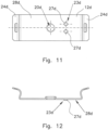
- Another alternative brace 12d shows Fig. 10 in a perspective view from above.
- the clip 12d has an alignment aid 23d with two projections 27d .
- These projections 27d are pin-shaped and are formed in particular by embossing the clip 12d.
- a fastening opening 20d is provided, in particular arranged centrally.
- the two projections 27d of the alignment aid 23d are spaced from this fastening opening 20d. They are arranged off-center to the clip 12d both in the longitudinal direction L and transversely to the longitudinal direction L.
- the clasp 12d has a support surface 28d .
- the support surface 28d is essentially flat, in particular with the exception of the projections 27d of the alignment aid 23d. It encompasses - apart from the fastening tabs 24d - the entire clasp 12d. It thus encompasses more than 50% of the surface of the clasp 12d.
- the clip 12d is made of an electrically conductive material.
- it is also made of spring steel.
- interference currents for example high-frequency interference currents
- the support surface 28d can be diverted via the support surface 28d, generally via the clip 12d, to a support rail on which the clip 12d is mounted. It is particularly advantageous for the diversion that a clip attachment mounted on the clip 12d can rest over a large area on the support surface 28d.
- Fig. 12 shows a side view of the clasp 12d according to Fig. 10 or Fig. 11 . It can be seen in particular that the projections 27d of the alignment aid 23d protrude from the support surface 28d. Their height is preferably between 0.3 mm and 0.8 mm and in particular 0.5 mm.
- braces 12, 12b, 12c and 12d Different features of the braces according to the invention have been described in different embodiments of the braces 12, 12b, 12c and 12d. It is understood and is at least partly also apparent from Fig. 1 to Fig. 12 It can be seen that, unless otherwise described in an embodiment, the other clasps 12, 12b, 12c and 12d also have or at least can have the feature described for a particular clasp. For example, all clasps 12, 12b, 12c and 12d have fastening tabs analogous to the fastening tab 24b ( Fig. 6 ). All clips 12, 12b, 12c and 12d can also have dimensions corresponding to clip 12b.
- the shape of the fastening openings is generally independent of the number of fastening openings provided on a clasp.
- an eye-shaped fastening opening corresponding to the Mounting hole 20 ( Fig. 5 ) alternatively or in addition to one or more of the fastening openings 20b, 20c, 20d of the previous embodiments.
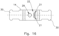
- Fig. 13 to Fig. 16 explain as an embodiment of a brace attachment the brace attachment 14 according to Fig. 1 closer.
- Fig. 13 a perspective view from the front
- Fig. 14 a side view
- Fig. 15 a sectional view according to section line AA of the Fig. 14
- Fig. 16 a top view of the clasp attachment 14.
- the clip attachment 14 has the two strain relief sections 30. As particularly shown in Fig. 13 As noted, the strain relief sections 30 each have lateral guide recesses 32 for cable ties or the like.
- Fig. 14 shows that the strain relief sections 30 are flat and run in the same plane. An object, for example a cable, can thus be placed on both strain relief sections 30.
- the object or cable can then be secured to the clip attachment 14 in the area of the guide recesses 32.
- the object can thus be relieved of strain in the area of both strain relief sections 30 and thus at both longitudinal ends of the clip attachment 14.
- the guide recesses 32 serve to ensure that the respective cable tie is arranged, in particular fixed, in a fixed position on the clip attachment 14 or on the respective strain relief section 30. A Slipping of a cable tie or the like from the clip attachment 14 can thus be prevented even when the object placed on it is loaded, in particular even when tensile forces act on the object.
- the clasp attachment 14 also has a fastening opening 29.
- this is also eye-shaped. It therefore also has two diameters of different lengths.
- the brace attachment 14 can be placed on the brace 12 ( Fig. 1 ) and secure it using the fastening hole 20 of the clip 12 ( Fig. 2 ), the fastening opening 29 of the clip attachment 14 and the rivet 18 ( Fig. 1 ) on the clip 12.
- the alignment aid 22 can be inserted with its projections 21 into one of the fastening openings 20 ( Fig. 2 ) of the underlying brace 12 and thus automatically fix the brace attachment 14 in its orientation and position relative to the brace 12.
- a clasp attachment is designed to be complementary to an alignment aid of a clasp.
- a clasp attachment has projections 27d of the alignment aid 23d ( Fig. 10 ) of the clip 12d complementary recesses are provided so that the interaction of the projections 27d with the complementary The recesses formed in turn result in automatic positioning and/or alignment.
- the alignment aid of the clasp attachment has only one projection or more than two projections, generally at least one projection.
- the at least one projection can be formed by embossing and/or by bending. It can be circular in cross-section. Alternatively, it can be non-circular in cross-section. In particular, it can be formed as a flat metal strip.
- clips, clip attachments and shield clamps have been described above. It is expressly conceivable to use these components in their different embodiments, in particular the clips 12, 12b, 12c, 12d, the clip attachment 14 and/or the shield clamps 16, 16a, also in combinations other than those described above, to form a carrier system, for example corresponding to the carrier system 10 according to Fig. 1 , to form.
- an elongated object for example a shielded cable
- a shield clamp for example the shield clamp 16 ( Fig. 1 ) or 16a ( Fig. 4 ).
- the shield clamp 16 or 16a can contact a shield of the object or cable.
- the object can be attached to the strain relief sections 30 ( Fig. 1 ) of the clip attachment 14 using cable ties or the like.
- All components of the carrier system in particular the carrier system 10 ( Fig. 1 ) or 10a ( Fig. 4 ) including the shield clamp 16 or 16a, can be made of an electrically conductive material, for example spring steel. In this way, any interference currents from the object, in particular from its shielding, can be diverted via the carrier system 10 or 10a to a carrier rail on which the carrier system 10 or 10a is mounted.
- the carrier system 10 or 10a can be mounted on the carrier rail without tools.
- the object fixed to the support system 10 or 10a is additionally protected against different loads, for example tensile forces on both sides, compared to previously conventional support systems.
Landscapes
- Engineering & Computer Science (AREA)
- Architecture (AREA)
- Civil Engineering (AREA)
- Structural Engineering (AREA)
- Clamps And Clips (AREA)
Claims (10)
- Système de support (10, 10a) pour la fixation d'un objet allongé sur un rail de support, comprenant une agrafe (12, 12b, 12c, 12d) pour la fixation du système de support (10, 10a) sur le rail de support et un élément rapporté formant agrafe (14), dans lequel l'élément rapporté formant agrafe (14) présente au moins deux sections de décharge de traction (30) permettant de décharger au moins deux fois la traction de l'objet, caractérisé en ce que l'agrafe (12, 12b, 12c, 12d) est conçue comme un dispositif d'encliquetage pour la fixation sans outil sur le rail de support et/ou l'agrafe (12, 12b, 12c, 12d) présente un tel dispositif d'encliquetage.
- Système de support selon la revendication 1, caractérisé en ce que le système de support comprend une pince de blindage (16, 16a).
- Système de support selon l'une des revendications précédentes, caractérisé en ce que l'agrafe (12, 12b, 12c, 12d) et/ou l'élément rapporté formant agrafe (14) sont conçus de manière à être symétriques.
- Système de support selon l'une des revendications précédentes, caractérisé en ce que l'agrafe (12, 12b, 12c, 12d) présente un moyen de fixation, en particulier une ouverture de fixation (20, 20b, 20c, 20d), pour la fixation de l'élément rapporté formant agrafe (14) et/ou de l'objet.
- Système de support selon la revendication 4, caractérisé en ce qu'une section transversale du moyen de fixation présente au moins deux diamètres (D1, D2) de longueurs différentes.
- Système de support selon l'une des revendications précédentes, caractérisé en ce que l'agrafe (12, 12b, 12c, 12d) présente au moins trois moyens de fixation, de préférence disposés en ligne, en particulier au moins trois ouvertures de fixation (20, 20b, 20c, 20d), pour la fixation de l'élément rapporté formant agrafe (14) et/ou de l'objet.
- Système de support selon l'une des revendications précédentes, caractérisé en ce que l'agrafe (12, 12b, 12c, 12d) et/ou l'élément rapporté formant agrafe (14) présentent un moyen d'aide à l'alignement (22, 23d) pour l'alignement et/ou le positionnement automatiques de l'élément rapporté formant agrafe (14) et/ou de l'objet par rapport à l'agrafe (12, 12b, 12c, 12d).
- Système de support selon l'une des revendications précédentes, caractérisé en ce que l'agrafe (12, 12b, 12c, 12d), l'élément rapporté formant agrafe (14) et/ou la pince de blindage (16, 16a) sont réalisés en un matériau électriquement conducteur, en particulier en un acier à ressort, et/ou présentent un tel matériau.
- Système de support selon l'une des revendications précédentes, caractérisé en ce que l'agrafe (12, 12b, 12c, 12d) présente au moins un moyen d'aide au détachement (26b) permettant de détacher l'agrafe (12, 12b, 12c, 12d) du rail de support.
- Système de support selon l'une des revendications précédentes, caractérisé en ce qu'au moins l'une des sections de décharge de traction (30) présente un dispositif de décharge de traction automatique.
Priority Applications (1)
| Application Number | Priority Date | Filing Date | Title |
|---|---|---|---|
| EP19190667.6A EP3772778B1 (fr) | 2019-08-08 | 2019-08-08 | Système porteur permettant de fixer un objet oblong ainsi qu'élément rapporté formant agrafe |
Applications Claiming Priority (1)
| Application Number | Priority Date | Filing Date | Title |
|---|---|---|---|
| EP19190667.6A EP3772778B1 (fr) | 2019-08-08 | 2019-08-08 | Système porteur permettant de fixer un objet oblong ainsi qu'élément rapporté formant agrafe |
Publications (2)
| Publication Number | Publication Date |
|---|---|
| EP3772778A1 EP3772778A1 (fr) | 2021-02-10 |
| EP3772778B1 true EP3772778B1 (fr) | 2024-10-23 |
Family
ID=67587448
Family Applications (1)
| Application Number | Title | Priority Date | Filing Date |
|---|---|---|---|
| EP19190667.6A Active EP3772778B1 (fr) | 2019-08-08 | 2019-08-08 | Système porteur permettant de fixer un objet oblong ainsi qu'élément rapporté formant agrafe |
Country Status (1)
| Country | Link |
|---|---|
| EP (1) | EP3772778B1 (fr) |
Families Citing this family (1)
| Publication number | Priority date | Publication date | Assignee | Title |
|---|---|---|---|---|
| DE102022109551B3 (de) | 2022-04-20 | 2023-08-10 | Hebotec Gmbh | Spange für ein Trägersystem |
Citations (5)
| Publication number | Priority date | Publication date | Assignee | Title |
|---|---|---|---|---|
| DE102009057514B3 (de) | 2009-12-10 | 2011-06-09 | Icotek Project Gmbh & Co. Kg | Vorrichtung zum Halten und Festklemmen eines Schirmkabels |
| EP2654128A1 (fr) | 2012-04-18 | 2013-10-23 | HEBOTEC GmbH | Dispositif de fixation |
| DE202015100063U1 (de) | 2015-01-08 | 2015-02-02 | Hebotec Gmbh | Spange zur Befestigung eines Bauelements |
| DE102016212179A1 (de) | 2016-07-05 | 2018-01-11 | Icotek Project Gmbh & Co. Kg | Kabelarmatur mit einer Schirmklemme und einer Zugentlastung |
| DE102018203554A1 (de) | 2017-03-16 | 2018-09-20 | Icotek Project Gmbh & Co. Kg | Schirmklemme |
-
2019
- 2019-08-08 EP EP19190667.6A patent/EP3772778B1/fr active Active
Patent Citations (5)
| Publication number | Priority date | Publication date | Assignee | Title |
|---|---|---|---|---|
| DE102009057514B3 (de) | 2009-12-10 | 2011-06-09 | Icotek Project Gmbh & Co. Kg | Vorrichtung zum Halten und Festklemmen eines Schirmkabels |
| EP2654128A1 (fr) | 2012-04-18 | 2013-10-23 | HEBOTEC GmbH | Dispositif de fixation |
| DE202015100063U1 (de) | 2015-01-08 | 2015-02-02 | Hebotec Gmbh | Spange zur Befestigung eines Bauelements |
| DE102016212179A1 (de) | 2016-07-05 | 2018-01-11 | Icotek Project Gmbh & Co. Kg | Kabelarmatur mit einer Schirmklemme und einer Zugentlastung |
| DE102018203554A1 (de) | 2017-03-16 | 2018-09-20 | Icotek Project Gmbh & Co. Kg | Schirmklemme |
Non-Patent Citations (10)
| Title |
|---|
| ANONYMOUS: " Kabeleinführungssysteme - EMV Lösungen", ICOTEK, 1 January 2016 (2016-01-01), XP093303511 |
| ANONYMOUS: " PROFINET - Montagerichtlinie (Version 1.0)", PROFI NET, 1 January 2009 (2009-01-01), XP093303513 |
| ANONYMOUS: "Integrierte Zugentlastung schützt den Kabelschirm", BESCHAFFUNG-AKTUELL.INDUSTRIE.DE, 29 March 2019 (2019-03-29), XP093303515, Retrieved from the Internet <URL:https://beschaffung-aktuell.industrie.de/allgemein/integrierte-zugentlastung-schuetzt-den-kabelschirm/> |
| D10 - RECHNUNG ÜBER DEN VERKAUF VON 3 EINHEITEN DES PRODUKTS SF2Z|SKL 3 6 (ARTIKELNUMMER 36855.150) AN DIE „IO INFRASTRUKTUR SERVICES UG" VOM 19.07.2019 |
| D11 - ZUORDNUNG DER KW 30 IN 2019 ZUR DEN ENTSPRECHENDEN DATEN |
| D12 - AUSSENDIENSTMITTEILUNG 15/2019 VOM 19.6.2029 IN DE, CN, EN, ES, JP |
| D13 - VERSANDLISTE DES SUPER-MAILERS ZUR D12 - EIGENSCHAFTEN DER TXT-DATEI |
| D14 - TXT- DATEI DER D13 |
| D15 - AUSDRUCK DER EMPFANGENEN E-MAIL BEI JAHNKE@ICOTEK.COM (#29 DER D13B) |
| D9 - Zeichnung des Produkts SF2Z|SKL 3-6 (Artikelnummer 36855.150) vom 25.2.2019 |
Also Published As
| Publication number | Publication date |
|---|---|
| EP3772778A1 (fr) | 2021-02-10 |
Similar Documents
| Publication | Publication Date | Title |
|---|---|---|
| EP2654128B1 (fr) | Dispositif de fixation | |
| EP2989685B1 (fr) | Borne à ressort à insertion directe | |
| EP3843221A1 (fr) | Cadre de support pour un connecteur | |
| EP3374234B1 (fr) | Système de fixation | |
| EP2458688B1 (fr) | Dispositif de fixation pour le développement d'une liaison électrique et/ou mécanique entre un rail électrique, une plaque de montage ou une surface de montage conductrice et une conducteur électrique | |
| EP3772778B1 (fr) | Système porteur permettant de fixer un objet oblong ainsi qu'élément rapporté formant agrafe | |
| DE102010002634B4 (de) | Befestigungsanordnung für Kabelführungen | |
| EP2913536A1 (fr) | Support d'antennes | |
| DE10035795B4 (de) | Klemmschuhanordnung | |
| DE3302752A1 (de) | Axialschub-sicherungsklemme fuer einen ein bauteil durchsetzenden bolzen | |
| DE19949509B4 (de) | Schirmklemme zur Anbindung von Kabelschirmen | |
| EP4060817B1 (fr) | Système de compensation de potentiel et système modulaire | |
| EP2913535B1 (fr) | Support d'antennes | |
| DE2604764C3 (de) | Elektrische Anschlußvorrichtung für eine gekapselte Kältemaschine | |
| DE20209246U1 (de) | Adapterplatte | |
| EP4002595A1 (fr) | Collier de mise à la terre pourvu de protection latérale contre la rotation | |
| DE102007054143B4 (de) | Anschlussvorrichtung | |
| EP0758805A1 (fr) | Barrette de continuité de masse | |
| EP3084860B1 (fr) | Borne de batterie | |
| AT402214B (de) | Leitungshalter für blitzableiterdrähte | |
| EP4135139B1 (fr) | Porte-composant pour composants électromécaniques | |
| DE102019120302B4 (de) | Leiteranschlussklemme, Klemmfeder einer Leiteranschlussklemme und Anordnung aus wenigstens zwei Klemmfedern | |
| DE202009009833U1 (de) | Anschlussvorrichtung für ein Schirmkabel | |
| EP3665395B1 (fr) | Collier pour la fixation d'un objet tubulaire | |
| DE202009016064U1 (de) | Kontaktelementanordnung sowie Anschlussvorrichtung für eine derartige Kontaktelementanordnung |
Legal Events
| Date | Code | Title | Description |
|---|---|---|---|
| PUAI | Public reference made under article 153(3) epc to a published international application that has entered the european phase |
Free format text: ORIGINAL CODE: 0009012 |
|
| STAA | Information on the status of an ep patent application or granted ep patent |
Free format text: STATUS: THE APPLICATION HAS BEEN PUBLISHED |
|
| AK | Designated contracting states |
Kind code of ref document: A1 Designated state(s): AL AT BE BG CH CY CZ DE DK EE ES FI FR GB GR HR HU IE IS IT LI LT LU LV MC MK MT NL NO PL PT RO RS SE SI SK SM TR |
|
| AX | Request for extension of the european patent |
Extension state: BA ME |
|
| STAA | Information on the status of an ep patent application or granted ep patent |
Free format text: STATUS: REQUEST FOR EXAMINATION WAS MADE |
|
| 17P | Request for examination filed |
Effective date: 20210609 |
|
| RBV | Designated contracting states (corrected) |
Designated state(s): AL AT BE BG CH CY CZ DE DK EE ES FI FR GB GR HR HU IE IS IT LI LT LU LV MC MK MT NL NO PL PT RO RS SE SI SK SM TR |
|
| STAA | Information on the status of an ep patent application or granted ep patent |
Free format text: STATUS: EXAMINATION IS IN PROGRESS |
|
| 17Q | First examination report despatched |
Effective date: 20220929 |
|
| REG | Reference to a national code |
Ref country code: DE Ref legal event code: R079 Free format text: PREVIOUS MAIN CLASS: H01R0004640000 Ipc: H02G0003320000 Ref country code: DE Ref legal event code: R079 Ref document number: 502019012333 Country of ref document: DE Free format text: PREVIOUS MAIN CLASS: H01R0004640000 Ipc: H02G0003320000 |
|
| GRAP | Despatch of communication of intention to grant a patent |
Free format text: ORIGINAL CODE: EPIDOSNIGR1 |
|
| STAA | Information on the status of an ep patent application or granted ep patent |
Free format text: STATUS: GRANT OF PATENT IS INTENDED |
|
| RIC1 | Information provided on ipc code assigned before grant |
Ipc: H01R 13/6582 20110101ALI20240614BHEP Ipc: H01R 25/14 20060101ALI20240614BHEP Ipc: H01R 4/48 20060101ALI20240614BHEP Ipc: H01R 13/58 20060101ALI20240614BHEP Ipc: H01R 4/64 20060101ALI20240614BHEP Ipc: H01R 9/26 20060101ALI20240614BHEP Ipc: H01R 9/24 20060101ALI20240614BHEP Ipc: H02G 3/32 20060101AFI20240614BHEP |
|
| INTG | Intention to grant announced |
Effective date: 20240712 |
|
| GRAS | Grant fee paid |
Free format text: ORIGINAL CODE: EPIDOSNIGR3 |
|
| GRAA | (expected) grant |
Free format text: ORIGINAL CODE: 0009210 |
|
| STAA | Information on the status of an ep patent application or granted ep patent |
Free format text: STATUS: THE PATENT HAS BEEN GRANTED |
|
| AK | Designated contracting states |
Kind code of ref document: B1 Designated state(s): AL AT BE BG CH CY CZ DE DK EE ES FI FR GB GR HR HU IE IS IT LI LT LU LV MC MK MT NL NO PL PT RO RS SE SI SK SM TR |
|
| REG | Reference to a national code |
Ref country code: GB Ref legal event code: FG4D Free format text: NOT ENGLISH |
|
| REG | Reference to a national code |
Ref country code: CH Ref legal event code: EP |
|
| REG | Reference to a national code |
Ref country code: DE Ref legal event code: R096 Ref document number: 502019012333 Country of ref document: DE |
|
| REG | Reference to a national code |
Ref country code: IE Ref legal event code: FG4D Free format text: LANGUAGE OF EP DOCUMENT: GERMAN |
|
| REG | Reference to a national code |
Ref country code: LT Ref legal event code: MG9D |
|
| REG | Reference to a national code |
Ref country code: NL Ref legal event code: MP Effective date: 20241023 |
|
| PG25 | Lapsed in a contracting state [announced via postgrant information from national office to epo] |
Ref country code: NL Free format text: LAPSE BECAUSE OF FAILURE TO SUBMIT A TRANSLATION OF THE DESCRIPTION OR TO PAY THE FEE WITHIN THE PRESCRIBED TIME-LIMIT Effective date: 20241023 |
|
| PG25 | Lapsed in a contracting state [announced via postgrant information from national office to epo] |
Ref country code: NL Free format text: LAPSE BECAUSE OF FAILURE TO SUBMIT A TRANSLATION OF THE DESCRIPTION OR TO PAY THE FEE WITHIN THE PRESCRIBED TIME-LIMIT Effective date: 20241023 |
|
| PG25 | Lapsed in a contracting state [announced via postgrant information from national office to epo] |
Ref country code: HR Free format text: LAPSE BECAUSE OF FAILURE TO SUBMIT A TRANSLATION OF THE DESCRIPTION OR TO PAY THE FEE WITHIN THE PRESCRIBED TIME-LIMIT Effective date: 20241023 Ref country code: IS Free format text: LAPSE BECAUSE OF FAILURE TO SUBMIT A TRANSLATION OF THE DESCRIPTION OR TO PAY THE FEE WITHIN THE PRESCRIBED TIME-LIMIT Effective date: 20250223 Ref country code: PT Free format text: LAPSE BECAUSE OF FAILURE TO SUBMIT A TRANSLATION OF THE DESCRIPTION OR TO PAY THE FEE WITHIN THE PRESCRIBED TIME-LIMIT Effective date: 20250224 |
|
| PG25 | Lapsed in a contracting state [announced via postgrant information from national office to epo] |
Ref country code: FI Free format text: LAPSE BECAUSE OF FAILURE TO SUBMIT A TRANSLATION OF THE DESCRIPTION OR TO PAY THE FEE WITHIN THE PRESCRIBED TIME-LIMIT Effective date: 20241023 |
|
| PG25 | Lapsed in a contracting state [announced via postgrant information from national office to epo] |
Ref country code: BG Free format text: LAPSE BECAUSE OF FAILURE TO SUBMIT A TRANSLATION OF THE DESCRIPTION OR TO PAY THE FEE WITHIN THE PRESCRIBED TIME-LIMIT Effective date: 20241023 |
|
| PG25 | Lapsed in a contracting state [announced via postgrant information from national office to epo] |
Ref country code: ES Free format text: LAPSE BECAUSE OF FAILURE TO SUBMIT A TRANSLATION OF THE DESCRIPTION OR TO PAY THE FEE WITHIN THE PRESCRIBED TIME-LIMIT Effective date: 20241023 |
|
| PG25 | Lapsed in a contracting state [announced via postgrant information from national office to epo] |
Ref country code: NO Free format text: LAPSE BECAUSE OF FAILURE TO SUBMIT A TRANSLATION OF THE DESCRIPTION OR TO PAY THE FEE WITHIN THE PRESCRIBED TIME-LIMIT Effective date: 20250123 |
|
| PG25 | Lapsed in a contracting state [announced via postgrant information from national office to epo] |
Ref country code: GR Free format text: LAPSE BECAUSE OF FAILURE TO SUBMIT A TRANSLATION OF THE DESCRIPTION OR TO PAY THE FEE WITHIN THE PRESCRIBED TIME-LIMIT Effective date: 20250124 Ref country code: LV Free format text: LAPSE BECAUSE OF FAILURE TO SUBMIT A TRANSLATION OF THE DESCRIPTION OR TO PAY THE FEE WITHIN THE PRESCRIBED TIME-LIMIT Effective date: 20241023 |
|
| PG25 | Lapsed in a contracting state [announced via postgrant information from national office to epo] |
Ref country code: PL Free format text: LAPSE BECAUSE OF FAILURE TO SUBMIT A TRANSLATION OF THE DESCRIPTION OR TO PAY THE FEE WITHIN THE PRESCRIBED TIME-LIMIT Effective date: 20241023 |
|
| PG25 | Lapsed in a contracting state [announced via postgrant information from national office to epo] |
Ref country code: RS Free format text: LAPSE BECAUSE OF FAILURE TO SUBMIT A TRANSLATION OF THE DESCRIPTION OR TO PAY THE FEE WITHIN THE PRESCRIBED TIME-LIMIT Effective date: 20250123 |
|
| PG25 | Lapsed in a contracting state [announced via postgrant information from national office to epo] |
Ref country code: SM Free format text: LAPSE BECAUSE OF FAILURE TO SUBMIT A TRANSLATION OF THE DESCRIPTION OR TO PAY THE FEE WITHIN THE PRESCRIBED TIME-LIMIT Effective date: 20241023 |
|
| PG25 | Lapsed in a contracting state [announced via postgrant information from national office to epo] |
Ref country code: DK Free format text: LAPSE BECAUSE OF FAILURE TO SUBMIT A TRANSLATION OF THE DESCRIPTION OR TO PAY THE FEE WITHIN THE PRESCRIBED TIME-LIMIT Effective date: 20241023 |
|
| PG25 | Lapsed in a contracting state [announced via postgrant information from national office to epo] |
Ref country code: EE Free format text: LAPSE BECAUSE OF FAILURE TO SUBMIT A TRANSLATION OF THE DESCRIPTION OR TO PAY THE FEE WITHIN THE PRESCRIBED TIME-LIMIT Effective date: 20241023 |
|
| REG | Reference to a national code |
Ref country code: DE Ref legal event code: R026 Ref document number: 502019012333 Country of ref document: DE |
|
| PG25 | Lapsed in a contracting state [announced via postgrant information from national office to epo] |
Ref country code: RO Free format text: LAPSE BECAUSE OF FAILURE TO SUBMIT A TRANSLATION OF THE DESCRIPTION OR TO PAY THE FEE WITHIN THE PRESCRIBED TIME-LIMIT Effective date: 20241023 |
|
| PG25 | Lapsed in a contracting state [announced via postgrant information from national office to epo] |
Ref country code: SK Free format text: LAPSE BECAUSE OF FAILURE TO SUBMIT A TRANSLATION OF THE DESCRIPTION OR TO PAY THE FEE WITHIN THE PRESCRIBED TIME-LIMIT Effective date: 20241023 |
|
| PLBI | Opposition filed |
Free format text: ORIGINAL CODE: 0009260 |
|
| PG25 | Lapsed in a contracting state [announced via postgrant information from national office to epo] |
Ref country code: CZ Free format text: LAPSE BECAUSE OF FAILURE TO SUBMIT A TRANSLATION OF THE DESCRIPTION OR TO PAY THE FEE WITHIN THE PRESCRIBED TIME-LIMIT Effective date: 20241023 |
|
| PG25 | Lapsed in a contracting state [announced via postgrant information from national office to epo] |
Ref country code: IT Free format text: LAPSE BECAUSE OF FAILURE TO SUBMIT A TRANSLATION OF THE DESCRIPTION OR TO PAY THE FEE WITHIN THE PRESCRIBED TIME-LIMIT Effective date: 20241023 |
|
| PLAX | Notice of opposition and request to file observation + time limit sent |
Free format text: ORIGINAL CODE: EPIDOSNOBS2 |
|
| 26 | Opposition filed |
Opponent name: ICOTEK GMBH & CO. KG Effective date: 20250723 |
|
| PG25 | Lapsed in a contracting state [announced via postgrant information from national office to epo] |
Ref country code: SE Free format text: LAPSE BECAUSE OF FAILURE TO SUBMIT A TRANSLATION OF THE DESCRIPTION OR TO PAY THE FEE WITHIN THE PRESCRIBED TIME-LIMIT Effective date: 20241023 |
|
| PGFP | Annual fee paid to national office [announced via postgrant information from national office to epo] |
Ref country code: DE Payment date: 20250825 Year of fee payment: 7 |
|
| PLBP | Opposition withdrawn |
Free format text: ORIGINAL CODE: 0009264 |
|
| REG | Reference to a national code |
Ref country code: CH Ref legal event code: L10 Free format text: ST27 STATUS EVENT CODE: U-0-0-L10-L00 (AS PROVIDED BY THE NATIONAL OFFICE) Effective date: 20251210 |
|
| PLBD | Termination of opposition procedure: decision despatched |
Free format text: ORIGINAL CODE: EPIDOSNOPC1 |
|
| PLAU | Termination of opposition procedure: information related to despatch of decision deleted |
Free format text: ORIGINAL CODE: EPIDOSDOPC1 |
|
| PLBD | Termination of opposition procedure: decision despatched |
Free format text: ORIGINAL CODE: EPIDOSNOPC1 |
|
| REG | Reference to a national code |
Ref country code: CH Ref legal event code: H13 Free format text: ST27 STATUS EVENT CODE: U-0-0-H10-H13 (AS PROVIDED BY THE NATIONAL OFFICE) Effective date: 20260324 |
|
| PG25 | Lapsed in a contracting state [announced via postgrant information from national office to epo] |
Ref country code: MC Free format text: LAPSE BECAUSE OF FAILURE TO SUBMIT A TRANSLATION OF THE DESCRIPTION OR TO PAY THE FEE WITHIN THE PRESCRIBED TIME-LIMIT Effective date: 20241023 |
|
| PG25 | Lapsed in a contracting state [announced via postgrant information from national office to epo] |
Ref country code: LU Free format text: LAPSE BECAUSE OF NON-PAYMENT OF DUE FEES Effective date: 20250808 |
|
| PG25 | Lapsed in a contracting state [announced via postgrant information from national office to epo] |
Ref country code: CH Free format text: LAPSE BECAUSE OF NON-PAYMENT OF DUE FEES Effective date: 20250831 |