EP3772788A1 - Élément de fixation et système de fixation - Google Patents
Élément de fixation et système de fixation Download PDFInfo
- Publication number
- EP3772788A1 EP3772788A1 EP19190707.0A EP19190707A EP3772788A1 EP 3772788 A1 EP3772788 A1 EP 3772788A1 EP 19190707 A EP19190707 A EP 19190707A EP 3772788 A1 EP3772788 A1 EP 3772788A1
- Authority
- EP
- European Patent Office
- Prior art keywords
- fastening element
- fastening
- base
- recess
- element according
- Prior art date
- Legal status (The legal status is an assumption and is not a legal conclusion. Google has not performed a legal analysis and makes no representation as to the accuracy of the status listed.)
- Granted
Links
Images


Classifications
-
- H—ELECTRICITY
- H02—GENERATION; CONVERSION OR DISTRIBUTION OF ELECTRIC POWER
- H02G—INSTALLATION OF ELECTRIC CABLES OR LINES, OR OF COMBINED OPTICAL AND ELECTRIC CABLES OR LINES
- H02G3/00—Installations of electric cables or lines or protective tubing therefor in or on buildings, equivalent structures or vehicles
- H02G3/30—Installations of cables or lines on walls, floors or ceilings
- H02G3/32—Installations of cables or lines on walls, floors or ceilings using mounting clamps
-
- F—MECHANICAL ENGINEERING; LIGHTING; HEATING; WEAPONS; BLASTING
- F16—ENGINEERING ELEMENTS AND UNITS; GENERAL MEASURES FOR PRODUCING AND MAINTAINING EFFECTIVE FUNCTIONING OF MACHINES OR INSTALLATIONS; THERMAL INSULATION IN GENERAL
- F16L—PIPES; JOINTS OR FITTINGS FOR PIPES; SUPPORTS FOR PIPES, CABLES OR PROTECTIVE TUBING; MEANS FOR THERMAL INSULATION IN GENERAL
- F16L3/00—Supports for pipes, cables or protective tubing, e.g. hangers, holders, clamps, cleats, clips, brackets
- F16L3/08—Supports for pipes, cables or protective tubing, e.g. hangers, holders, clamps, cleats, clips, brackets substantially surrounding the pipe, cable or protective tubing
- F16L3/12—Supports for pipes, cables or protective tubing, e.g. hangers, holders, clamps, cleats, clips, brackets substantially surrounding the pipe, cable or protective tubing comprising a member substantially surrounding the pipe, cable or protective tubing
- F16L3/137—Supports for pipes, cables or protective tubing, e.g. hangers, holders, clamps, cleats, clips, brackets substantially surrounding the pipe, cable or protective tubing comprising a member substantially surrounding the pipe, cable or protective tubing and consisting of a flexible band
-
- H—ELECTRICITY
- H02—GENERATION; CONVERSION OR DISTRIBUTION OF ELECTRIC POWER
- H02G—INSTALLATION OF ELECTRIC CABLES OR LINES, OR OF COMBINED OPTICAL AND ELECTRIC CABLES OR LINES
- H02G3/00—Installations of electric cables or lines or protective tubing therefor in or on buildings, equivalent structures or vehicles
- H02G3/30—Installations of cables or lines on walls, floors or ceilings
Definitions
- the invention is based on a fastening element for the detachable fastening of at least one elongate object, for example a cable or a pipe, on a substrate, for example a profile rail, comprising a base that can be fastened to the substrate, the base having a curved support surface for the object and wherein the base has a fixing tape receptacle for receiving a fixing tape, in particular a Velcro tape, with which the object can be releasably fastened on the support surface.
- a fastening element for the detachable fastening of at least one elongate object, for example a cable or a pipe, on a substrate, for example a profile rail, comprising a base that can be fastened to the substrate, the base having a curved support surface for the object and wherein the base has a fixing tape receptacle for receiving a fixing tape, in particular a Velcro tape, with which the object can be releasably fastened on the support surface.
- Such a fastener is from DE 10 2014 101 745 A1 known, the fastening system there being assignable to the fastening element together with the fixing strap.
- the teaching of this publication is hereby expressly incorporated by reference.
- fastening element can be used in a particularly versatile manner.
- different objects for example different cables, connectors, pipes or the like, can be securely fastened and used on different substrates with one or more fastening elements of the same type.
- a fastening element for the detachable fastening of at least one elongate object to a substrate comprising a base that can be fastened to the substrate, the base having a curved support surface for the object and the base having a fixing strap receptacle for receiving a fixing strap with which the object can be releasably fastened on the support surface, the support surface having at least two support arcs with different support circular arcs in a plane perpendicular to the longitudinal direction of the base and / or the fastening element having a stop for fixing the object against displacement along at least one loading direction.
- the elongate object can be a cable, a pipe and / or a plug connector and / or can have such a cable.
- the subsurface can be a profile rail.
- the fixing tape can be and / or have a Velcro tape.
- the invention is based on the idea of offering a fastening element which, due to its geometry, is set up to receive objects of different shapes, in particular objects of different sizes, particularly safely.
- the at least two different circular support radii make it possible to place round objects, for example cables or pipes, with different diameters in a precisely fitting manner on the support surface.
- the support surface can be formed from at least two differently curved support sub-surfaces and / or have at least two such support sub-surfaces.
- the partial support surfaces can each be designed as a partial lateral surface of a cylinder with a cylinder radius corresponding to one of the at least two different circular support arc radii.
- the fastening element has a stop for fixing the object against displacement along at least one loading direction.
- the stop can be formed on the base and / or as part of the base.
- the stop can preferably be arranged and / or formed on an end face of the fastening element, in particular its base.
- the loading direction or the loading directions can run parallel to the longitudinal direction of the base.
- the fastening element does not have a stop.
- other types of objects in particular elongate objects, in addition to cables, hoses, pipes and the like, can also be attached to the fastening element.
- the fastening element is particularly suitable, for example, for fastening plugs, sockets and / or connectors in general.
- the fastening element can be designed for multiple sizes of plugs, sockets or connectors.
- the curvature of the support surface can have support circular arc radii adapted to the respective sizes or the associated radii. Then the different objects can be held particularly securely and without play.
- the arc center points associated with the arcs can be offset from one another. For example, they can be offset outwards, that is, away from the support surface. Then different connectors from small to large from the inside, i. H. close to the support surface, outwards, d. H. facing away from the support surface, wherein each connector of any size can rest on the support surface at least in a section of the support surface without play.
- the stop can have a recess. A cable or the like protruding from a connector can be led out of the fastening element through this recess.
- the recess has at least two recess circular arcs with different recess arc radii and / or with different recess arc centers in a plane perpendicular to the longitudinal direction of the base.
- cables of different diameters protruding from different connectors rest against the same recess without play and / or stress-free.
- a plurality of such cables or the like can also be arranged in the recess simultaneously without play and / or without stress.
- the recess can be designed with different circular arc radii and preferably with correspondingly offset circular arc centers corresponding to the different sizes of the objects, in particular the plug connectors.
- different plug-in connectors of different sizes can be fixed on the respective stop and in particular on the end face, while their cables or the like can be kept free from any mechanical stress or load.
- several cables or the like can be strain relieved.
- the fastening element in particular the base, can have at least one through-channel through which the fixing strap can pass.
- the fixing tape can be fixed at one end in and / or on the fixing tape holder.
- the fixing tape can wrap around the object.
- the fixing tape can be passed through the passage channel at the other end. In this way, the effective length of the fixing tape can be quickly and easily adapted to the object or objects.
- the through channel has at least one insertion bevel, preferably two insertion bevels.
- the at least one insertion bevel can run at an, in particular acute, angle to a base area of the through-channel.
- the base can be curved.
- the at least one insertion bevel can also be curved.
- the through channel can be formed by at least three segments, in particular by the two lead-in bevels and the base area. This makes it possible to guide the fixing tape into or out of the through-channel at an elevated position. This makes the fastening element much easier to use. This also allows several fastening elements to be arranged closer to one another on, for example, a common substrate.
- the fastening element can have a fastening means, for example a screw, a slot nut, a pin or the like, and / or a fastening recess, in particular for receiving such a fastening means, for fastening the fastening element to the substrate.
- the fastening means and / or the fastening recess can preferably be arranged outside the through-channel, in particular in front of or behind the through-channel when viewed in the longitudinal direction.
- the fastening means and / or the fastening recess can be arranged outside the base area of the through channel. This also facilitates the implementation of the fixing tape through the passage channel.
- the fastening element can thereby be designed to be less high.
- the fastening element has an alignment aid for automatic alignment and / or positioning of the fastening element relative to the substrate.
- the alignment aid can be designed, for example, as the underside of the fastening element and, in particular, as a protrusion projecting on the side opposite the support surface.
- the alignment aid can be designed to engage positively in a recess in the subsurface that is formed complementary to the alignment aid.
- the fastening element can thus be precisely and easily fastened to the substrate with a predefined orientation and / or position.
- the alignment aid can also be designed to be flexibly deformable.
- the fastening element can be mounted on different substrates in a particularly simple and / or play-free manner.
- the alignment aid can be designed to be retractable in the fastening element.
- the alignment aid can have a spring tongue which can be lowered into a recess in the fastening element. If the fastening element is thus mounted on a substrate without a complementary recess, the alignment aid disappears in the recess of the fastening element. In the other case, when the base has a corresponding, complementarily formed recess, the alignment aid can engage in this recess and thus align and / or position the fastening element.
- the fastening element can have electrical insulation.
- the fastening element, in particular the base can be formed from a non-conductive material and / or have such a material.
- the fastening element, in particular the base can have a coating made of the non-conductive material.
- the fastening element in particular the base, can be formed from a conductive material, in particular from a conductive plastic and / or from a metal, and / or have such a material.
- the fastening element, in particular the base can have a coating made of the conductive material. The fastening element can thus be electrically conductive.
- the object fastened to the fastening element can be earthed, in particular if the substrate is also earthed.
- the fastening element can be formed from a plastic and / or have a plastic. It can be manufactured in a casting process.
- the fastening element in particular the fixing strap receptacle, can have teeth on which the fixing strap can be fixed.
- the fixing tape especially if it is designed as a Velcro tape, can be hooked into the toothing with its fleece side.
- the fixing strap can then be connected to the fastening element in a particularly simple manner at least at one end.
- the scope of the invention also includes a fastening system comprising two fastening elements according to the invention, both fastening elements each having at least one stop.
- the scope of the invention also includes a use of a fastening element according to the invention and / or a fastening system according to the invention and / or in a drag chain.
- Drag chains are often exposed to very strong accelerations. Supply lines, control lines and the like that are routed via such a drag chain are therefore also subject to strong accelerations.
- FIGS. 1, 2 and 3 show a fastening system 10 in perspective views obliquely from above and obliquely from below and in a side view.
- the fastening system 10 has two fastening elements 12 , to each of which two connectors 16, 18 are fastened by means of a fastening strap 14 each.
- the fastening elements 12 and thus the fastening system 10 are on a substrate 24 (only in Fig. 1 shown) releasably attached.
- the base 24 can be, for example, a switchboard, a profile rail or the like.
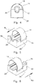
- FIGS. 4, 5 and 6 show a fastening element 12 in a view of an end face or in two perspective views, to which a fixing strap 14 is fastened.
- Fig. 7 shows a perspective view of one of the two fastening elements 12 without a fixing strap 14.
- the fastening element 12 has a base 26 .
- the fastening element 12 is formed in one piece.
- the base 26 is thus designed as a partial area of the fastening element 12.
- the fastening element 12 is attached to the substrate 24 ( Fig. 1 ) attachable.
- the base 26 has a curved support surface 28 on an upper side.
- the support surface 28 is to support the connectors 16, 18 ( Fig. 1 ) educated.
- the fastening element 12 also has a stop 30 on the front side.
- the stop 30 prevents the connector 16 or 18 received in the fastening element 12 from being displaced along at least one load direction B ( Fig. 6 ), in particular in the direction of the stop 30, prevented.
- the connector 16 as shown in FIG Fig. 4 due to the stop 30 are not shifted out of the image plane in the direction of the viewer.
- the loading direction B runs parallel to the longitudinal direction L ( Fig. 6 ) of the base 26.
- the fixing tape 14 is designed as a Velcro tape. How in particular from Fig. 7 results, it is received and fastened at one end in one of two fixing tape receptacles 32 in the base 26 and thus in the fastening element 12.
- the fixing strap receptacles 32 each have toothings 34 .
- the fixing strap 14 is passed through the base 26 at the other end via two lead-in bevels 36 and along a base surface 38 .
- the base area 38 is preferably curved.
- the insertion bevels 36 thus together with the base surface 38 form a through channel 40.
- the fixing strap 14 can thus connect the connector 16 ( Fig. 4 ) loop around and fix it to the fastening element 12.
- the base 26 has a fastening recess 42 which is located next to the passage 40.
- the fastening recess 42 By means of the fastening recess 42, the fastening element 12 can be attached to the substrate 24 ( Fig. 1 ) are fastened, in particular releasably, with the aid of a screw or the like.
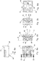
- Figure 8a shows a fastening element 12 in a view from above and Figure 8b in a sectional view along the section line BB of Figure 8a .
- the insertion bevels 36 run at an angle alpha obliquely to the at least substantially flat underside of the base 26.
- the angle alpha is between 20 ° and 50 °, in particular 30 °.
- the support surface 28 is curved.
- the support surface is formed in a plane of the base 26 that corresponds to the section line BB and is perpendicular to the longitudinal direction L by two support circular arcs with different support circular arc radii R1, R2 .
- the arc center points L1, L2 belonging to the arcs are offset from one another.
- the support arc radii R1, R2 and the position of the support arc center points L1 and L2 are matched to the objects to be fastened to the fastening element 12, in particular to different types of connectors such as the connector 16 or 18 ( Fig. 1 ).
- the stop 30 has a recess 44 .
- the recess 44 points in one to the image plane of the Figure 8c parallel and thus in one to the longitudinal direction L ( Figure 8a ) of the base 26 vertical plane on two recess circular arcs, the two recess circular arcs having different recess circular arc radii K1 and K2 .
- the associated circular arc center points M1 and M2 are also offset from one another.
- the two circular arcs of the recess with their different circular recess radii K1, K2 and their circular arc centers M1, M2 are matched to the objects provided for fastening on the fastening element 12.
- Figure 8d shows a view of the fastening element 12 from below and Figure 8e from one side.
- An alignment aid 46 can be seen.
- the alignment aid 46 has an elevation 48 protruding downward from the fastening element 12 or from the base 26 in the (unloaded state). If the underground 24 ( Fig. 1 ), to which the fastening element 12 is to be fastened, has a recess formed complementarily to the elevation 48, the elevation 48 can engage in the corresponding recess of the substrate 24 and thereby align the fastening element 12 on the substrate 24, in particular automatically, and / or relatively to the ground 24, in particular also automatically position.
- the elevation 48 is at one end on a spring tongue 50 ( Figure 8d ) the alignment aid 46 is arranged.
- the spring tongue 50 is connected to the rest of the base 26 at only one end. It is free from the base 26 on the other sides.
- the fastening element 12 also has a recess 52 ( Figure 8a ) on.
- the alignment aid 46 can thus be sunk in the fastening element 12 with its spring tongue 50 by pressure from outside, for example on the elevation 48. In particular, it is thereby possible to countersink the alignment aid 46 so deeply in the fastening element 12 that the elevation 48 is flush with the underside of the base 26.
- the fastening element 12 can nevertheless be fastened flush and without play on the base 24, since in this case the alignment aid 46 disappears, in particular automatically, through elastic deformation of the spring tongue 50 in the fastening element 12 .
- the fastening element 12 is made from a non-conductive material, in particular from a non-conductive plastic.
- the fastening element 12 is manufactured by means of injection molding.
- the fastening system 10 described and the fastening element 12 can be used with a wide variety of substrates 24 ( Fig. 1 ) use.
- the fastening system 10 or the fastening element 12 can be used on a drag chain (not shown in the figures).
- the fastening system 10 or the fastening element 12 can preferably be used in areas that move along with it and / or in areas of the drag chain that are subject to strong accelerations.
- the drag chain can have a carrier on which the fastening system 10 or the fastening element 12, in particular by means of its fastening recess 42 ( Fig. 7 ) and, if necessary, can be fastened using a fastening means such as a screw or a rivet.
- a plug connector or the like to be carried along with the drag chain can then be securely fixed on the fastening system 10 or on the fastening element 12.
Landscapes
- Engineering & Computer Science (AREA)
- General Engineering & Computer Science (AREA)
- Architecture (AREA)
- Civil Engineering (AREA)
- Structural Engineering (AREA)
- Mechanical Engineering (AREA)
- Clamps And Clips (AREA)
Priority Applications (1)
| Application Number | Priority Date | Filing Date | Title |
|---|---|---|---|
| EP19190707.0A EP3772788B1 (fr) | 2019-08-08 | 2019-08-08 | Élément de fixation et système de fixation |
Applications Claiming Priority (1)
| Application Number | Priority Date | Filing Date | Title |
|---|---|---|---|
| EP19190707.0A EP3772788B1 (fr) | 2019-08-08 | 2019-08-08 | Élément de fixation et système de fixation |
Publications (2)
| Publication Number | Publication Date |
|---|---|
| EP3772788A1 true EP3772788A1 (fr) | 2021-02-10 |
| EP3772788B1 EP3772788B1 (fr) | 2024-02-07 |
Family
ID=67658572
Family Applications (1)
| Application Number | Title | Priority Date | Filing Date |
|---|---|---|---|
| EP19190707.0A Active EP3772788B1 (fr) | 2019-08-08 | 2019-08-08 | Élément de fixation et système de fixation |
Country Status (1)
| Country | Link |
|---|---|
| EP (1) | EP3772788B1 (fr) |
Cited By (1)
| Publication number | Priority date | Publication date | Assignee | Title |
|---|---|---|---|---|
| CN114771086A (zh) * | 2022-05-25 | 2022-07-22 | 深圳市至臻精密股份有限公司 | 一种智能化高精度丝印机 |
Citations (5)
| Publication number | Priority date | Publication date | Assignee | Title |
|---|---|---|---|---|
| DE1910241A1 (de) * | 1969-02-28 | 1970-09-03 | Hellermann Gmbh P | Klebesockel zur Befestigung von Kabelbaeumen |
| US3632069A (en) * | 1970-02-11 | 1972-01-04 | Panduit Corp | Bracket for mounting cable bundles in lightening holes |
| US6561473B1 (en) * | 2001-03-30 | 2003-05-13 | Pirod, Inc. | Universal pipe mounting clamp and assembly |
| DE102014101745A1 (de) | 2014-02-12 | 2015-08-13 | Hebotec Gmbh | Befestigungssystem |
| JP2015201908A (ja) * | 2014-04-04 | 2015-11-12 | 未来工業株式会社 | 配線・配管材保持具に対する配線・配管材の結束方法、波付管保持具、及び配線・配管材保持具 |
Family Cites Families (1)
| Publication number | Priority date | Publication date | Assignee | Title |
|---|---|---|---|---|
| DE3731149C2 (de) * | 1987-09-16 | 1996-08-29 | Siemens Ag | Zugentlastung für eine Anschlußschnur |
-
2019
- 2019-08-08 EP EP19190707.0A patent/EP3772788B1/fr active Active
Patent Citations (6)
| Publication number | Priority date | Publication date | Assignee | Title |
|---|---|---|---|---|
| DE1910241A1 (de) * | 1969-02-28 | 1970-09-03 | Hellermann Gmbh P | Klebesockel zur Befestigung von Kabelbaeumen |
| US3632069A (en) * | 1970-02-11 | 1972-01-04 | Panduit Corp | Bracket for mounting cable bundles in lightening holes |
| US6561473B1 (en) * | 2001-03-30 | 2003-05-13 | Pirod, Inc. | Universal pipe mounting clamp and assembly |
| DE102014101745A1 (de) | 2014-02-12 | 2015-08-13 | Hebotec Gmbh | Befestigungssystem |
| EP2908039A1 (fr) * | 2014-02-12 | 2015-08-19 | HEBOTEC GmbH | Système de fixation |
| JP2015201908A (ja) * | 2014-04-04 | 2015-11-12 | 未来工業株式会社 | 配線・配管材保持具に対する配線・配管材の結束方法、波付管保持具、及び配線・配管材保持具 |
Cited By (2)
| Publication number | Priority date | Publication date | Assignee | Title |
|---|---|---|---|---|
| CN114771086A (zh) * | 2022-05-25 | 2022-07-22 | 深圳市至臻精密股份有限公司 | 一种智能化高精度丝印机 |
| CN114771086B (zh) * | 2022-05-25 | 2024-02-02 | 深圳市至臻精密股份有限公司 | 一种智能化高精度丝印机 |
Also Published As
| Publication number | Publication date |
|---|---|
| EP3772788B1 (fr) | 2024-02-07 |
Similar Documents
| Publication | Publication Date | Title |
|---|---|---|
| DE102015114814B4 (de) | System aus Steckverbinder-Modulrahmen und Adapterelementen sowie modularen Steckverbinder mit einem solchen System | |
| DE102014101745A1 (de) | Befestigungssystem | |
| EP3374234B1 (fr) | Système de fixation | |
| EP2012390B1 (fr) | Pince de mise à la terre destinée à l'équilibrage du potentiel de canaux de câblage | |
| DE112016004037B4 (de) | Befestigungsvorrichtung, vorrangig zur Montage einer Antenne an einem Fahrzeug | |
| EP3772788B1 (fr) | Élément de fixation et système de fixation | |
| DE102016124609A1 (de) | Verteilerkasten zum Einbau in eine Wandöffnung | |
| DE202008005734U1 (de) | Modulares System zur Befestigung von vorzugsweise Leitungen oder Rohren in einem Flugzeug | |
| DE202010015763U1 (de) | Vorrichtung zur Positionierung wenigstens eines Rundsteckers | |
| DE202014105219U1 (de) | Erdungsschienenvorrichtung | |
| DE202017107700U1 (de) | Schnellwechsler, Adapter und Schnellwechselsystem | |
| DE102014110278A1 (de) | Halterahmen für Steckverbindermodule und/oder Steckverbinder | |
| EP0724104A1 (fr) | Elément d'atténuation de contraintes et de fixation | |
| DE102017130437A1 (de) | Schnellwechsler, Adapter und Schnellwechselsystem | |
| DE102011107610A1 (de) | Leitungshalter zur Befestigung an einem Träger einer Flugzeugstruktur | |
| DE202010009722U1 (de) | Kabel- und Leitungsführung | |
| DE202014101359U1 (de) | Endbefestigungsteil für Leitungsführungseinrichtung | |
| DE2557697B2 (de) | Abdeckvorrichtung mit einem schwenkbaren deckel fuer das gehaeuse eines geraets | |
| EP2902265B1 (fr) | Support d'écran | |
| EP2538510B1 (fr) | Panier d'appareillage pour installations électriques souterraines | |
| DE102010032579A1 (de) | Dachantennenanordnung eines Fahrzeuges mit einem U-förmigen Federelement zur Festlegung der Dachantennenanordnung | |
| DE102017115013B3 (de) | Kontaktträgeranordnung und Verfahren zur Montage der Kontaktträgeranordnung | |
| DE102014007863A1 (de) | Halteeinrichtung für einen Querträger in einem elektrischen Schaltschrank und Schaltschrank mit einer solchen Einrichtung | |
| DE19809902B4 (de) | Außenrückblickspiegel | |
| DE102015210565B4 (de) | Vorrichtung und verfahren zum befestigen von medienleitungen an einem träger |
Legal Events
| Date | Code | Title | Description |
|---|---|---|---|
| PUAI | Public reference made under article 153(3) epc to a published international application that has entered the european phase |
Free format text: ORIGINAL CODE: 0009012 |
|
| STAA | Information on the status of an ep patent application or granted ep patent |
Free format text: STATUS: THE APPLICATION HAS BEEN PUBLISHED |
|
| AK | Designated contracting states |
Kind code of ref document: A1 Designated state(s): AL AT BE BG CH CY CZ DE DK EE ES FI FR GB GR HR HU IE IS IT LI LT LU LV MC MK MT NL NO PL PT RO RS SE SI SK SM TR |
|
| AX | Request for extension of the european patent |
Extension state: BA ME |
|
| STAA | Information on the status of an ep patent application or granted ep patent |
Free format text: STATUS: REQUEST FOR EXAMINATION WAS MADE |
|
| 17P | Request for examination filed |
Effective date: 20210420 |
|
| RBV | Designated contracting states (corrected) |
Designated state(s): AL AT BE BG CH CY CZ DE DK EE ES FI FR GB GR HR HU IE IS IT LI LT LU LV MC MK MT NL NO PL PT RO RS SE SI SK SM TR |
|
| STAA | Information on the status of an ep patent application or granted ep patent |
Free format text: STATUS: EXAMINATION IS IN PROGRESS |
|
| 17Q | First examination report despatched |
Effective date: 20220311 |
|
| GRAP | Despatch of communication of intention to grant a patent |
Free format text: ORIGINAL CODE: EPIDOSNIGR1 |
|
| STAA | Information on the status of an ep patent application or granted ep patent |
Free format text: STATUS: GRANT OF PATENT IS INTENDED |
|
| RIC1 | Information provided on ipc code assigned before grant |
Ipc: H02G 3/30 20060101ALN20231009BHEP Ipc: F16L 3/137 20060101ALI20231009BHEP Ipc: H02G 3/32 20060101AFI20231009BHEP |
|
| INTG | Intention to grant announced |
Effective date: 20231025 |
|
| RIC1 | Information provided on ipc code assigned before grant |
Ipc: H02G 3/30 20060101ALN20231016BHEP Ipc: F16L 3/137 20060101ALI20231016BHEP Ipc: H02G 3/32 20060101AFI20231016BHEP |
|
| GRAS | Grant fee paid |
Free format text: ORIGINAL CODE: EPIDOSNIGR3 |
|
| GRAA | (expected) grant |
Free format text: ORIGINAL CODE: 0009210 |
|
| STAA | Information on the status of an ep patent application or granted ep patent |
Free format text: STATUS: THE PATENT HAS BEEN GRANTED |
|
| AK | Designated contracting states |
Kind code of ref document: B1 Designated state(s): AL AT BE BG CH CY CZ DE DK EE ES FI FR GB GR HR HU IE IS IT LI LT LU LV MC MK MT NL NO PL PT RO RS SE SI SK SM TR |
|
| REG | Reference to a national code |
Ref country code: GB Ref legal event code: FG4D Free format text: NOT ENGLISH |
|
| REG | Reference to a national code |
Ref country code: CH Ref legal event code: EP |
|
| REG | Reference to a national code |
Ref country code: DE Ref legal event code: R096 Ref document number: 502019010527 Country of ref document: DE |
|
| REG | Reference to a national code |
Ref country code: IE Ref legal event code: FG4D Free format text: LANGUAGE OF EP DOCUMENT: GERMAN |
|
| REG | Reference to a national code |
Ref country code: LT Ref legal event code: MG9D |
|
| REG | Reference to a national code |
Ref country code: NL Ref legal event code: MP Effective date: 20240207 |
|
| PG25 | Lapsed in a contracting state [announced via postgrant information from national office to epo] |
Ref country code: IS Free format text: LAPSE BECAUSE OF FAILURE TO SUBMIT A TRANSLATION OF THE DESCRIPTION OR TO PAY THE FEE WITHIN THE PRESCRIBED TIME-LIMIT Effective date: 20240607 |
|
| PG25 | Lapsed in a contracting state [announced via postgrant information from national office to epo] |
Ref country code: LT Free format text: LAPSE BECAUSE OF FAILURE TO SUBMIT A TRANSLATION OF THE DESCRIPTION OR TO PAY THE FEE WITHIN THE PRESCRIBED TIME-LIMIT Effective date: 20240207 |
|
| PG25 | Lapsed in a contracting state [announced via postgrant information from national office to epo] |
Ref country code: GR Free format text: LAPSE BECAUSE OF FAILURE TO SUBMIT A TRANSLATION OF THE DESCRIPTION OR TO PAY THE FEE WITHIN THE PRESCRIBED TIME-LIMIT Effective date: 20240508 |
|
| PG25 | Lapsed in a contracting state [announced via postgrant information from national office to epo] |
Ref country code: RS Free format text: LAPSE BECAUSE OF FAILURE TO SUBMIT A TRANSLATION OF THE DESCRIPTION OR TO PAY THE FEE WITHIN THE PRESCRIBED TIME-LIMIT Effective date: 20240507 Ref country code: NL Free format text: LAPSE BECAUSE OF FAILURE TO SUBMIT A TRANSLATION OF THE DESCRIPTION OR TO PAY THE FEE WITHIN THE PRESCRIBED TIME-LIMIT Effective date: 20240207 Ref country code: HR Free format text: LAPSE BECAUSE OF FAILURE TO SUBMIT A TRANSLATION OF THE DESCRIPTION OR TO PAY THE FEE WITHIN THE PRESCRIBED TIME-LIMIT Effective date: 20240207 |
|
| PG25 | Lapsed in a contracting state [announced via postgrant information from national office to epo] |
Ref country code: ES Free format text: LAPSE BECAUSE OF FAILURE TO SUBMIT A TRANSLATION OF THE DESCRIPTION OR TO PAY THE FEE WITHIN THE PRESCRIBED TIME-LIMIT Effective date: 20240207 |
|
| PG25 | Lapsed in a contracting state [announced via postgrant information from national office to epo] |
Ref country code: RS Free format text: LAPSE BECAUSE OF FAILURE TO SUBMIT A TRANSLATION OF THE DESCRIPTION OR TO PAY THE FEE WITHIN THE PRESCRIBED TIME-LIMIT Effective date: 20240507 Ref country code: NO Free format text: LAPSE BECAUSE OF FAILURE TO SUBMIT A TRANSLATION OF THE DESCRIPTION OR TO PAY THE FEE WITHIN THE PRESCRIBED TIME-LIMIT Effective date: 20240507 Ref country code: NL Free format text: LAPSE BECAUSE OF FAILURE TO SUBMIT A TRANSLATION OF THE DESCRIPTION OR TO PAY THE FEE WITHIN THE PRESCRIBED TIME-LIMIT Effective date: 20240207 Ref country code: LT Free format text: LAPSE BECAUSE OF FAILURE TO SUBMIT A TRANSLATION OF THE DESCRIPTION OR TO PAY THE FEE WITHIN THE PRESCRIBED TIME-LIMIT Effective date: 20240207 Ref country code: IS Free format text: LAPSE BECAUSE OF FAILURE TO SUBMIT A TRANSLATION OF THE DESCRIPTION OR TO PAY THE FEE WITHIN THE PRESCRIBED TIME-LIMIT Effective date: 20240607 Ref country code: HR Free format text: LAPSE BECAUSE OF FAILURE TO SUBMIT A TRANSLATION OF THE DESCRIPTION OR TO PAY THE FEE WITHIN THE PRESCRIBED TIME-LIMIT Effective date: 20240207 Ref country code: GR Free format text: LAPSE BECAUSE OF FAILURE TO SUBMIT A TRANSLATION OF THE DESCRIPTION OR TO PAY THE FEE WITHIN THE PRESCRIBED TIME-LIMIT Effective date: 20240508 Ref country code: FI Free format text: LAPSE BECAUSE OF FAILURE TO SUBMIT A TRANSLATION OF THE DESCRIPTION OR TO PAY THE FEE WITHIN THE PRESCRIBED TIME-LIMIT Effective date: 20240207 Ref country code: ES Free format text: LAPSE BECAUSE OF FAILURE TO SUBMIT A TRANSLATION OF THE DESCRIPTION OR TO PAY THE FEE WITHIN THE PRESCRIBED TIME-LIMIT Effective date: 20240207 Ref country code: BG Free format text: LAPSE BECAUSE OF FAILURE TO SUBMIT A TRANSLATION OF THE DESCRIPTION OR TO PAY THE FEE WITHIN THE PRESCRIBED TIME-LIMIT Effective date: 20240207 |
|
| PG25 | Lapsed in a contracting state [announced via postgrant information from national office to epo] |
Ref country code: PL Free format text: LAPSE BECAUSE OF FAILURE TO SUBMIT A TRANSLATION OF THE DESCRIPTION OR TO PAY THE FEE WITHIN THE PRESCRIBED TIME-LIMIT Effective date: 20240207 Ref country code: PT Free format text: LAPSE BECAUSE OF FAILURE TO SUBMIT A TRANSLATION OF THE DESCRIPTION OR TO PAY THE FEE WITHIN THE PRESCRIBED TIME-LIMIT Effective date: 20240607 |
|
| PG25 | Lapsed in a contracting state [announced via postgrant information from national office to epo] |
Ref country code: SE Free format text: LAPSE BECAUSE OF FAILURE TO SUBMIT A TRANSLATION OF THE DESCRIPTION OR TO PAY THE FEE WITHIN THE PRESCRIBED TIME-LIMIT Effective date: 20240207 Ref country code: PT Free format text: LAPSE BECAUSE OF FAILURE TO SUBMIT A TRANSLATION OF THE DESCRIPTION OR TO PAY THE FEE WITHIN THE PRESCRIBED TIME-LIMIT Effective date: 20240607 Ref country code: PL Free format text: LAPSE BECAUSE OF FAILURE TO SUBMIT A TRANSLATION OF THE DESCRIPTION OR TO PAY THE FEE WITHIN THE PRESCRIBED TIME-LIMIT Effective date: 20240207 Ref country code: LV Free format text: LAPSE BECAUSE OF FAILURE TO SUBMIT A TRANSLATION OF THE DESCRIPTION OR TO PAY THE FEE WITHIN THE PRESCRIBED TIME-LIMIT Effective date: 20240207 |
|
| PG25 | Lapsed in a contracting state [announced via postgrant information from national office to epo] |
Ref country code: DK Free format text: LAPSE BECAUSE OF FAILURE TO SUBMIT A TRANSLATION OF THE DESCRIPTION OR TO PAY THE FEE WITHIN THE PRESCRIBED TIME-LIMIT Effective date: 20240207 |
|
| PG25 | Lapsed in a contracting state [announced via postgrant information from national office to epo] |
Ref country code: SM Free format text: LAPSE BECAUSE OF FAILURE TO SUBMIT A TRANSLATION OF THE DESCRIPTION OR TO PAY THE FEE WITHIN THE PRESCRIBED TIME-LIMIT Effective date: 20240207 |
|
| PG25 | Lapsed in a contracting state [announced via postgrant information from national office to epo] |
Ref country code: EE Free format text: LAPSE BECAUSE OF FAILURE TO SUBMIT A TRANSLATION OF THE DESCRIPTION OR TO PAY THE FEE WITHIN THE PRESCRIBED TIME-LIMIT Effective date: 20240207 Ref country code: CZ Free format text: LAPSE BECAUSE OF FAILURE TO SUBMIT A TRANSLATION OF THE DESCRIPTION OR TO PAY THE FEE WITHIN THE PRESCRIBED TIME-LIMIT Effective date: 20240207 |
|
| PG25 | Lapsed in a contracting state [announced via postgrant information from national office to epo] |
Ref country code: SK Free format text: LAPSE BECAUSE OF FAILURE TO SUBMIT A TRANSLATION OF THE DESCRIPTION OR TO PAY THE FEE WITHIN THE PRESCRIBED TIME-LIMIT Effective date: 20240207 |
|
| PG25 | Lapsed in a contracting state [announced via postgrant information from national office to epo] |
Ref country code: SM Free format text: LAPSE BECAUSE OF FAILURE TO SUBMIT A TRANSLATION OF THE DESCRIPTION OR TO PAY THE FEE WITHIN THE PRESCRIBED TIME-LIMIT Effective date: 20240207 Ref country code: SK Free format text: LAPSE BECAUSE OF FAILURE TO SUBMIT A TRANSLATION OF THE DESCRIPTION OR TO PAY THE FEE WITHIN THE PRESCRIBED TIME-LIMIT Effective date: 20240207 Ref country code: RO Free format text: LAPSE BECAUSE OF FAILURE TO SUBMIT A TRANSLATION OF THE DESCRIPTION OR TO PAY THE FEE WITHIN THE PRESCRIBED TIME-LIMIT Effective date: 20240207 Ref country code: EE Free format text: LAPSE BECAUSE OF FAILURE TO SUBMIT A TRANSLATION OF THE DESCRIPTION OR TO PAY THE FEE WITHIN THE PRESCRIBED TIME-LIMIT Effective date: 20240207 Ref country code: DK Free format text: LAPSE BECAUSE OF FAILURE TO SUBMIT A TRANSLATION OF THE DESCRIPTION OR TO PAY THE FEE WITHIN THE PRESCRIBED TIME-LIMIT Effective date: 20240207 Ref country code: CZ Free format text: LAPSE BECAUSE OF FAILURE TO SUBMIT A TRANSLATION OF THE DESCRIPTION OR TO PAY THE FEE WITHIN THE PRESCRIBED TIME-LIMIT Effective date: 20240207 |
|
| REG | Reference to a national code |
Ref country code: DE Ref legal event code: R097 Ref document number: 502019010527 Country of ref document: DE |
|
| PG25 | Lapsed in a contracting state [announced via postgrant information from national office to epo] |
Ref country code: IT Free format text: LAPSE BECAUSE OF FAILURE TO SUBMIT A TRANSLATION OF THE DESCRIPTION OR TO PAY THE FEE WITHIN THE PRESCRIBED TIME-LIMIT Effective date: 20240207 |
|
| PLBE | No opposition filed within time limit |
Free format text: ORIGINAL CODE: 0009261 |
|
| STAA | Information on the status of an ep patent application or granted ep patent |
Free format text: STATUS: NO OPPOSITION FILED WITHIN TIME LIMIT |
|
| PG25 | Lapsed in a contracting state [announced via postgrant information from national office to epo] |
Ref country code: IT Free format text: LAPSE BECAUSE OF FAILURE TO SUBMIT A TRANSLATION OF THE DESCRIPTION OR TO PAY THE FEE WITHIN THE PRESCRIBED TIME-LIMIT Effective date: 20240207 |
|
| 26N | No opposition filed |
Effective date: 20241108 |
|
| REG | Reference to a national code |
Ref country code: CH Ref legal event code: PL |
|
| PG25 | Lapsed in a contracting state [announced via postgrant information from national office to epo] |
Ref country code: LU Free format text: LAPSE BECAUSE OF NON-PAYMENT OF DUE FEES Effective date: 20240808 |
|
| GBPC | Gb: european patent ceased through non-payment of renewal fee |
Effective date: 20240808 |
|
| PG25 | Lapsed in a contracting state [announced via postgrant information from national office to epo] |
Ref country code: SI Free format text: LAPSE BECAUSE OF FAILURE TO SUBMIT A TRANSLATION OF THE DESCRIPTION OR TO PAY THE FEE WITHIN THE PRESCRIBED TIME-LIMIT Effective date: 20240207 Ref country code: MC Free format text: LAPSE BECAUSE OF FAILURE TO SUBMIT A TRANSLATION OF THE DESCRIPTION OR TO PAY THE FEE WITHIN THE PRESCRIBED TIME-LIMIT Effective date: 20240207 Ref country code: CH Free format text: LAPSE BECAUSE OF NON-PAYMENT OF DUE FEES Effective date: 20240831 |
|
| REG | Reference to a national code |
Ref country code: BE Ref legal event code: MM Effective date: 20240831 |
|
| PG25 | Lapsed in a contracting state [announced via postgrant information from national office to epo] |
Ref country code: GB Free format text: LAPSE BECAUSE OF NON-PAYMENT OF DUE FEES Effective date: 20240808 |
|
| PG25 | Lapsed in a contracting state [announced via postgrant information from national office to epo] |
Ref country code: BE Free format text: LAPSE BECAUSE OF NON-PAYMENT OF DUE FEES Effective date: 20240831 |
|
| PG25 | Lapsed in a contracting state [announced via postgrant information from national office to epo] |
Ref country code: FR Free format text: LAPSE BECAUSE OF NON-PAYMENT OF DUE FEES Effective date: 20240831 |
|
| PG25 | Lapsed in a contracting state [announced via postgrant information from national office to epo] |
Ref country code: IE Free format text: LAPSE BECAUSE OF NON-PAYMENT OF DUE FEES Effective date: 20240808 |
|
| PGFP | Annual fee paid to national office [announced via postgrant information from national office to epo] |
Ref country code: DE Payment date: 20250825 Year of fee payment: 7 |
|
| REG | Reference to a national code |
Ref country code: AT Ref legal event code: MM01 Ref document number: 1655990 Country of ref document: AT Kind code of ref document: T Effective date: 20240808 |
|
| PG25 | Lapsed in a contracting state [announced via postgrant information from national office to epo] |
Ref country code: AT Free format text: LAPSE BECAUSE OF NON-PAYMENT OF DUE FEES Effective date: 20240808 |
|
| PG25 | Lapsed in a contracting state [announced via postgrant information from national office to epo] |
Ref country code: CY Free format text: LAPSE BECAUSE OF FAILURE TO SUBMIT A TRANSLATION OF THE DESCRIPTION OR TO PAY THE FEE WITHIN THE PRESCRIBED TIME-LIMIT; INVALID AB INITIO Effective date: 20190808 |
|
| PG25 | Lapsed in a contracting state [announced via postgrant information from national office to epo] |
Ref country code: HU Free format text: LAPSE BECAUSE OF FAILURE TO SUBMIT A TRANSLATION OF THE DESCRIPTION OR TO PAY THE FEE WITHIN THE PRESCRIBED TIME-LIMIT; INVALID AB INITIO Effective date: 20190808 |