EP3773105B1 - Dispositif de séparation pour dispositif aspirateur de poussière - Google Patents
Dispositif de séparation pour dispositif aspirateur de poussière Download PDFInfo
- Publication number
- EP3773105B1 EP3773105B1 EP19713089.1A EP19713089A EP3773105B1 EP 3773105 B1 EP3773105 B1 EP 3773105B1 EP 19713089 A EP19713089 A EP 19713089A EP 3773105 B1 EP3773105 B1 EP 3773105B1
- Authority
- EP
- European Patent Office
- Prior art keywords
- separator
- tube
- separating device
- dirt particles
- outlet opening
- Prior art date
- Legal status (The legal status is an assumption and is not a legal conclusion. Google has not performed a legal analysis and makes no representation as to the accuracy of the status listed.)
- Active
Links
Images








Classifications
-
- A—HUMAN NECESSITIES
- A47—FURNITURE; DOMESTIC ARTICLES OR APPLIANCES; COFFEE MILLS; SPICE MILLS; SUCTION CLEANERS IN GENERAL
- A47L—DOMESTIC WASHING OR CLEANING; SUCTION CLEANERS IN GENERAL
- A47L9/00—Details or accessories of suction cleaners, e.g. mechanical means for controlling the suction or for effecting pulsating action; Storing devices specially adapted to suction cleaners or parts thereof; Carrying-vehicles specially adapted for suction cleaners
- A47L9/10—Filters; Dust separators; Dust removal; Automatic exchange of filters
- A47L9/102—Dust separators
- A47L9/104—Means for intercepting small objects
-
- A—HUMAN NECESSITIES
- A47—FURNITURE; DOMESTIC ARTICLES OR APPLIANCES; COFFEE MILLS; SPICE MILLS; SUCTION CLEANERS IN GENERAL
- A47L—DOMESTIC WASHING OR CLEANING; SUCTION CLEANERS IN GENERAL
- A47L5/00—Structural features of suction cleaners
- A47L5/12—Structural features of suction cleaners with power-driven air-pumps or air-compressors, e.g. driven by motor vehicle engine vacuum
- A47L5/22—Structural features of suction cleaners with power-driven air-pumps or air-compressors, e.g. driven by motor vehicle engine vacuum with rotary fans
- A47L5/36—Suction cleaners with hose between nozzle and casing; Suction cleaners for fixing on staircases; Suction cleaners for carrying on the back
- A47L5/365—Suction cleaners with hose between nozzle and casing; Suction cleaners for fixing on staircases; Suction cleaners for carrying on the back of the vertical type, e.g. tank or bucket type
-
- A—HUMAN NECESSITIES
- A47—FURNITURE; DOMESTIC ARTICLES OR APPLIANCES; COFFEE MILLS; SPICE MILLS; SUCTION CLEANERS IN GENERAL
- A47L—DOMESTIC WASHING OR CLEANING; SUCTION CLEANERS IN GENERAL
- A47L9/00—Details or accessories of suction cleaners, e.g. mechanical means for controlling the suction or for effecting pulsating action; Storing devices specially adapted to suction cleaners or parts thereof; Carrying-vehicles specially adapted for suction cleaners
- A47L9/10—Filters; Dust separators; Dust removal; Automatic exchange of filters
- A47L9/16—Arrangement or disposition of cyclones or other devices with centrifugal action
- A47L9/1616—Multiple arrangement thereof
- A47L9/1625—Multiple arrangement thereof for series flow
- A47L9/1633—Concentric cyclones
-
- A—HUMAN NECESSITIES
- A47—FURNITURE; DOMESTIC ARTICLES OR APPLIANCES; COFFEE MILLS; SPICE MILLS; SUCTION CLEANERS IN GENERAL
- A47L—DOMESTIC WASHING OR CLEANING; SUCTION CLEANERS IN GENERAL
- A47L9/00—Details or accessories of suction cleaners, e.g. mechanical means for controlling the suction or for effecting pulsating action; Storing devices specially adapted to suction cleaners or parts thereof; Carrying-vehicles specially adapted for suction cleaners
- A47L9/10—Filters; Dust separators; Dust removal; Automatic exchange of filters
- A47L9/16—Arrangement or disposition of cyclones or other devices with centrifugal action
- A47L9/1616—Multiple arrangement thereof
- A47L9/1641—Multiple arrangement thereof for parallel flow
-
- A—HUMAN NECESSITIES
- A47—FURNITURE; DOMESTIC ARTICLES OR APPLIANCES; COFFEE MILLS; SPICE MILLS; SUCTION CLEANERS IN GENERAL
- A47L—DOMESTIC WASHING OR CLEANING; SUCTION CLEANERS IN GENERAL
- A47L9/00—Details or accessories of suction cleaners, e.g. mechanical means for controlling the suction or for effecting pulsating action; Storing devices specially adapted to suction cleaners or parts thereof; Carrying-vehicles specially adapted for suction cleaners
- A47L9/10—Filters; Dust separators; Dust removal; Automatic exchange of filters
- A47L9/16—Arrangement or disposition of cyclones or other devices with centrifugal action
- A47L9/1658—Construction of outlets
-
- A—HUMAN NECESSITIES
- A47—FURNITURE; DOMESTIC ARTICLES OR APPLIANCES; COFFEE MILLS; SPICE MILLS; SUCTION CLEANERS IN GENERAL
- A47L—DOMESTIC WASHING OR CLEANING; SUCTION CLEANERS IN GENERAL
- A47L9/00—Details or accessories of suction cleaners, e.g. mechanical means for controlling the suction or for effecting pulsating action; Storing devices specially adapted to suction cleaners or parts thereof; Carrying-vehicles specially adapted for suction cleaners
- A47L9/10—Filters; Dust separators; Dust removal; Automatic exchange of filters
- A47L9/16—Arrangement or disposition of cyclones or other devices with centrifugal action
- A47L9/1683—Dust collecting chambers; Dust collecting receptacles
-
- A—HUMAN NECESSITIES
- A47—FURNITURE; DOMESTIC ARTICLES OR APPLIANCES; COFFEE MILLS; SPICE MILLS; SUCTION CLEANERS IN GENERAL
- A47L—DOMESTIC WASHING OR CLEANING; SUCTION CLEANERS IN GENERAL
- A47L9/00—Details or accessories of suction cleaners, e.g. mechanical means for controlling the suction or for effecting pulsating action; Storing devices specially adapted to suction cleaners or parts thereof; Carrying-vehicles specially adapted for suction cleaners
- A47L9/10—Filters; Dust separators; Dust removal; Automatic exchange of filters
- A47L9/16—Arrangement or disposition of cyclones or other devices with centrifugal action
- A47L9/1691—Mounting or coupling means for cyclonic chamber or dust receptacles
-
- B—PERFORMING OPERATIONS; TRANSPORTING
- B04—CENTRIFUGAL APPARATUS OR MACHINES FOR CARRYING-OUT PHYSICAL OR CHEMICAL PROCESSES
- B04C—APPARATUS USING FREE VORTEX FLOW, e.g. CYCLONES
- B04C3/00—Apparatus in which the axial direction of the vortex flow following a screw-thread type line remains unchanged ; Devices in which one of the two discharge ducts returns centrally through the vortex chamber, a reverse-flow vortex being prevented by bulkheads in the central discharge duct
- B04C3/04—Multiple arrangement thereof
-
- B—PERFORMING OPERATIONS; TRANSPORTING
- B04—CENTRIFUGAL APPARATUS OR MACHINES FOR CARRYING-OUT PHYSICAL OR CHEMICAL PROCESSES
- B04C—APPARATUS USING FREE VORTEX FLOW, e.g. CYCLONES
- B04C3/00—Apparatus in which the axial direction of the vortex flow following a screw-thread type line remains unchanged ; Devices in which one of the two discharge ducts returns centrally through the vortex chamber, a reverse-flow vortex being prevented by bulkheads in the central discharge duct
- B04C3/06—Construction of inlets or outlets to the vortex chamber
Definitions
- the present invention relates to a separating device that can be connected to a vacuum cleaning device for separating dirt particles from an air flow sucked in by the vacuum cleaning device, containing at least one separator.
- a vacuum cleaning device or a vacuum cleaner is usually used in combination with the machine tool in order to suck in the dust that has been thrown up.
- the vacuum cleaner usually includes a filter to retain dust and dirt particles that get inside the vacuum cleaner from the sucked air. Without a filter, the dust or dirt particles sucked in could damage the turbine, which is used to generate a negative pressure inside the vacuum cleaning device, and/or the sensitive electronics of the vacuum cleaning device, which are used to control, regulate and monitor the vacuum cleaning device.
- the sucked-in dust and dirt particles get stuck in the pores of the filter. After a certain period of time, the dust and dirt particles can become so clogged that the filter is no longer effective.
- a separator can be used in the vacuum cleaner.
- the separator is used to separate dirt particles that are in the sucked-in air and is positioned in the vacuum cleaner in such a way that a large part of the sucked-in dirt particles are already removed from the air before the air flows through the filter. By separating a large part of the dirt particles with the help of the separator, the service life of the filter can be increased.
- Vacuum cleaning devices with a separate separation device are already available on the market. The vacuum cleaners available on the market with a separating device, however, have the problem that the separating device is completely filled with sucked dust and dirt particles after only a relatively short time, so that the function of the separating device is no longer guaranteed.
- these separating devices that are already available on the market are usually attached to the vacuum cleaning device from the outside as a separate component.
- the attachment to the vacuum cleaner is cumbersome and makes the vacuum cleaner larger and more difficult to handle.
- FR 2 558 741 A1 discloses a separator for a mixture of a vapor and a liquid using centrifugation within a housing.
- WO 2003 030 703 A2 discloses a cyclonic separator to be placed on the suction path of a vacuum cleaner, preferably coaxially between an extension tube and a handle.
- the object of the present invention is to solve the problem described above and in particular to provide a compact separating device for a vacuum cleaning device with a longer service life.
- a separating device that can be connected to a vacuum cleaning device for separating dirt particles from an air flow sucked in by the vacuum cleaning device, containing at least one separator.
- the at least one separator contains an inlet opening for the air flow and a first and second outlet opening, the first outlet opening for the exit of sucked dirt particles from the cyclone separator and the second outlet opening for the exit of the sucked air flow and the sucked Dirt particles from the separator is used, and a first and a second collection storage is included for collecting the dirt particles separated from the separator, and the first collection storage is positioned in a direction below the first outlet opening and the second collection storage is positioned in a direction below the second outlet opening, the cyclone separator is designed in the form of an axial separator with a first and a second tube, the second tube can be repositioned at least partially in the first tube and the first outlet opening is in the form of a recess in the lateral surface of the first Tube and is provided at an annular gap between the first and second tube.
- the separator can be designed in the form of a cyclone separator.
- first and second collection storage are included for collecting the dirt particles separated from the cyclone separator. It is also possible that only a single accumulator is provided.
- the cyclone separator can also be referred to as a centrifugal separator, cyclone, cyclone filter or swirler.
- the cyclone separator is designed in the form of an axial separator with a first and a second tube, the second tube being releasably positionable at least partially in the first tube.
- the first and second tube can be connected to one another in a detachable manner.
- the cyclone separator can be designed in such a way that the first and second tubes are firmly connected to one another.
- a base element of the first and second collection storage can be designed in the form of a non-return flap, so that the dirt particles collected in the collection storage can fall out of the collection storage when the base element designed as a non-return flap is opened.
- the base element can also be referred to as an opening element.
- the separating device can be positioned in relation to a collection container of a vacuum cleaning device in such a way that the base element, designed as a non-return flap, of the first and second collection storage can be opened towards the collection container.
- the dirt particles collected in the collection reservoir can be conveyed into the collection container of a vacuum cleaning device with the aid of gravity.
- the configuration of the base element in the form of a non-return flap can effectively prevent air and dirt particles from getting from the collection container of the vacuum cleaning device via the collection storage into the cyclone separator or into the separating device.
- the non-return flap it can be possible for the non-return flap to be designed to be elastically deformable. As a result, a non-return valve that functions almost silently can be implemented in a simple manner.
- the separating device can contain a frame housing which can be positioned between a suction head and a collection container of the vacuum cleaning device.
- the separating device can be retrofitted in a modular manner into existing vacuum cleaning devices with a suction head and a collection container.
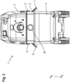
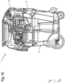
- figure 1 , 2 and 3 1 shows a separating device 2 according to the invention connected to a vacuum cleaning device 1 for separating dirt particles from an air flow LS sucked in by the vacuum cleaning device 1 .
- the vacuum cleaning device 1 essentially contains a suction head 3 and a collection container 4.
- the suction head 3 is positioned in the direction of the arrow A above the collection container 4 and is releasably connected to it.
- the separating device 2 is releasably connected to the suction head 3 by means of a first and second clip fastener 5, 6 and to the collection container 4 by means of a third and fourth clip fastener 7, 8, so that the separating device 2 is positioned between the suction head 3 and the collection container 4.
- the suction head 3 essentially contains a turbine for generating a negative pressure in the vacuum cleaning device 1 and a controller with electronics that is used to control, regulate and monitor the vacuum cleaning device 1 . With the aid of the negative pressure, ambient air can be sucked into the interior of the vacuum cleaning device 1 for collecting dust and dirt particles. Neither the turbine nor the control with the electronics are shown in the figures.
- the collection container 4 is designed essentially in the form of a trough with a cavity for collecting dust and dirt particles.
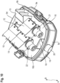
- the separating device 2 essentially contains a frame housing 9, a first and second separator 21, 22 as well as a first, second, third and fourth accumulator 12, 13, 14, 15.
- the frame case 9 is generally in the form of a tub with a bottom wall 16 and includes an upper end 9a, a lower end 9b, a front end 9c and a rear end 9d.
- the bottom wall 16 in turn includes a top 16a and a bottom 16b.
- the frame housing 9 includes a side wall 17.
- the side wall 17 extends around the entire frame housing 9 and includes an inflow channel 18 at the front end 9c of the frame housing 9.
- an inflow port 20 is positioned on an outer side 19 of the side wall 17 and Also at the front end 9c of the frame housing 9, an inflow port 20 is positioned.
- the inflow nozzle 20 can also be integrated in the collection container 4 .
- the inflow nozzle 20 is used to attach one end of a vacuum cleaner hose.
- the vacuum cleaner hose is not shown in the figures.
- the inflow connection piece 20 and the inflow channel 18 are fluidically connected to one another in such a way that an air flow LS sucked in by the vacuum cleaner 1 can flow through the inflow connection piece 20 and the inflow channel 18 to the underside 16b of the bottom wall 16 .
- the first and second separators 21, 22 are on the underside of the bottom wall 16. Both the first and second separators 21, 22 are designed in the form of an axial separator or an axial cyclone separator. However, it is also possible that another type of separator, such as a cyclone separator, tangential cyclone separator or multi-cyclone, is used. It is not necessary for the first and second separators 21, 22 to be of identical construction.
- the first and second separators 21, 22 are positioned and aligned parallel to one another, so that an air flow LS drawn in can flow through the first and second separators 21, 22 at the same time. According to an alternative embodiment, more than one first and second separator 21, 22 can also be provided. It is also possible that only a single separator is provided.
- a series arrangement with a plurality of separating cascades, each consisting of one or more precipitators, can be provided.
- the first and second separators 21, 22 essentially comprise first and second tubes 21a, 22a, 21b, 22b, respectively.
- the first pipe 21a, 22a serves as the inlet pipe and the second pipe 21b, 22b as the immersion pipe.
- the first and second separators 21, 22 also each contain an inlet opening 23 for an air flow LS sucked in by the vacuum cleaning device 1, as well as a first and second outlet opening 21c, 22c, 21d, 22d.
- the first outlet opening 21c, 22c is used for the exit of sucked dirt particles from the separator 21, 22 and the second outlet opening 21d, 22d for the exit of the sucked air flow LS and the sucked dirt particles from the separator 21, 22.
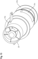
- the first tube 21a, 22a consists of a cylindrical part and a conical part.
- a guide device in the form of guide vanes 23a for generating a swirl in the intake air flow LS is positioned in the cylindrical portion.
- an annular elevation 24 is provided on a lateral surface, which extends around the lateral surface and serves to fasten the first tube 21a, 22a to the accumulator 12, 14.
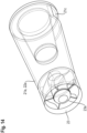
- the first outlet opening 21c, 22c in the form of a recess is provided in the lateral surface of the conical portion, cf. figure 16 .
- the first outlet opening 21c, 22c serves as an outlet opening for dirt particles that have accumulated in the first tube 21a, 22a of the separator 21, 22.
- the second tube 21b, 22b also consists of a cylindrical part and a conical part.
- a first and second annular elevation 26, 27 is provided on a lateral surface. Both the first and second annular elevations 26, 27 extend around the lateral surface.
- the first annular elevation 26 is used for the releasable attachment of the second tube 21b, 22b to the first tube 21a, 22a.
- the free end 28 of the conical portion of the first tube 21a, 22a goes into a plug-in connection with the first annular elevation 26 of the second tube 21b, 22b.
- the second annular elevation 27 is used in each case to fasten the second tube 21b, 22b to the accumulator 13, 15.
- the second outlet opening 21d, 22d is provided at the free end of the second tube 21b, 22b and serves to discharge the airflow LS sucked into the separator 21, 22 and the dirt particles still remaining in the sucked-in airflow LS.
- the second tube 21b, 22b is partially positioned within the first tube 21a, 22a. A certain portion of the second tube 21b, 22b extends outside the first tube 21a, 22a. As a result, an annular gap RS is formed between the first tube 21a, 22a and the second tube 21b, 22b, in which dirt particles collect, which are sucked in by the vacuum cleaning device 1 together with the air flow LS.
- the separating device 2 also contains a first, second, third and fourth storage tank 12, 13, 14, 15, which are also positioned on the underside 16b of the bottom wall 16.
- the first separator 21 is positioned in the first and second storage tanks 12, 13 and the second separator 22 in the third and fourth storage tanks 14, 15.
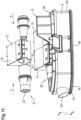
- the accumulator 12, 13, 14, 15 essentially contains a wedge-shaped box 30 with a cylindrical tube 31.
- the wedge-shaped box 30 includes a first side wall 30a, a second side wall 30b, a rear wall 30c and a bottom member 30d.
- the inclined plane 32 of the wedge-shaped box 30 forms the bottom element 30d of the collecting storage 12, 13, 14, 15.
- the bottom element 30d is designed in the form of a non-return flap, so that by opening the non-return flap in the direction of the arrow R, R', the dirt particles collected in the collecting storage 12, 13, 14, 15 can be removed from the collecting storage 12, 13, 14, 15 can fall in direction B, cf. figure 6 .
- the bottom element 30d designed as a non-return flap is designed to be elastically deformable, so that the non-return flap 30d can be moved reversibly between an open and a closed position. In the Figures 4 to 12 the bottom element 30d designed as a non-return flap is shown in the closed position.
- the first and second side walls 30a, 30b each contain a recess 33 for receiving the cylindrical tube 31.
- the cylindrical tube 31 is arranged in relation to the wedge-shaped box 30 such that the central longitudinal axis MLA of the cylindrical tube runs parallel to the bottom element 30d.
- the first tube 21a is stretched in the direction of the arrow C into the cylindrical tube 31 of the first accumulator 12.
- the second tube 22a is stretched into the cylindrical tube 31 of the first accumulator 12 in the direction of arrow D.
- FIG. The second tube 22a is stretched into the first tube 21a.
- the free end of the second tube 22a, which extends from the cylindrical tube 31 of the first accumulator 12, is inserted in the direction of arrow C into the cylindrical tube 31 of the second accumulator 13.
- the first pipe 21a of the first separator 21 is arranged in the first collecting storage 12 in such a way that the first outlet opening 21c designed as a cutout in the first pipe 21a faces the base element 30d designed as a non-return valve.
- dirt particles collected in the first cyclone separator can fall out of the first separator 21 and into the collection container 4 of the vacuum cleaning device 1 through the first outlet opening 21c of the first pipe 21a designed as a recess and through the base element 30d designed as a non-return flap.
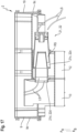
- the second outlet port 21d of the second tube 21b extending from the cylindrical tube 31 of the second accumulator 13 is located located in the direction of the arrow B above the bottom element 30d of the second collecting store, which is designed as a non-return flap, cf. figure 17 .
- the inlet port 23 of the first pipe 21a faces the inflow nozzle 20 and the inflow port 18 so that the inflow port 20, the inflow port 20 and the inlet port 23 are in fluid communication with each other.
- An air flow LS sucked in by the vacuum cleaning device 1 can thus flow through the inflow nozzle 20 , the inflow channel 18 and into the inlet opening 23 of the first separator 21 .
- the air flow LS, cleaned of the dirt particles reaches the second pipe 21b and through the second outlet opening
- the first pipe 22a of the second separator 22 is stretched in the direction of the arrow C into the cylindrical tube 31 of the third accumulator 14.
- the second tube 22b of the second separator 22 is stretched in the direction of arrow D into the cylindrical tube 31 of the third accumulator 14.
- FIG. The second tube 22b is stretched into the first tube 22a.
- the free end of the second tube 22b, which extends from the cylindrical tube 31 of the third accumulator 14, is inserted in the direction of arrow C into the cylindrical tube 31 of the fourth accumulator 15.
- the first pipe 22a of the second separator 22 is arranged in the third collecting storage 14 in such a way that the first outlet opening 22c designed as a cutout in the first pipe 22a faces the base element 30d designed as a non-return valve.
- dirt particles collected in the second separator 22 can fall out of the second separator 22 and into the collection container 4 of the vacuum cleaning device 1 through the first outlet opening 22c of the first pipe 22b designed as a recess and through the bottom element 30d designed as a non-return flap.
- the second outlet opening 22d of the second tube 22b, which extends from the cylindrical tube 31 of the fourth accumulator 15 is located in the direction of the arrow B above the base element 30d of the fourth accumulator 15, which is designed as a non-return valve, cf. figure 17 .
- the inlet port 23 of the first tube 22a faces the inflow nozzle 20 and the inflow port 18 so that the inflow port 20, the inflow port 18 and the inlet port 23 are in fluid communication with each other.
- An air flow LS sucked in by the vacuum cleaning device 1 can thus flow through the inflow nozzle 20 , the inflow channel 18 and into the inlet opening 23 of the second separator 22 .
- the dirt particles reach the collection container 4 of the vacuum cleaning device 1 through the base element 30d, which is designed as a non-return flap.
- the air flow LS from which almost all dirt particles have now been separated, flows through the filter of the vacuum cleaning device 1.
- the separating device 2 according to the invention is shown according to a second exemplary embodiment.
- the separating device 2 according to the first exemplary embodiment is essentially identical to the separating device 2 according to the second exemplary embodiment.
- the second tube 21b, 22b of the first and second separator 21, 22 is not straight but curved.
- the respective second pipe 21b, 22b of the first and second separator 21, 22 contains an elbow element KE, which points in the direction of the arrow B.
- the accumulators 12, 13 of the separating device 2 do not contain any base elements 30d designed as non-return flaps.
- the accumulators 12, 13 contain non-return flaps on the longitudinal sides 40 of the accumulators 12, 13, which are designed vertically, i.e. running in the direction of the arrow A or B.
Landscapes
- Engineering & Computer Science (AREA)
- Mechanical Engineering (AREA)
- Filters For Electric Vacuum Cleaners (AREA)
- Cyclones (AREA)
Claims (4)
- Dispositif de séparation (2) pouvant être relié à un dispositif d'aspiration de poussière (1) pour la séparation de particules de saleté à partir d'un courant d'air (LS) aspiré par le dispositif d'aspiration de poussière (1), contenant au moins un séparateur (21, 22), l'au moins un séparateur (21, 22) contenant une ouverture d'entrée (23) pour le courant d'air (LS) ainsi qu'une première et une deuxième ouverture de sortie (21 c, 22c), la première ouverture de sortie (21 c, 22c) servant à la sortie des particules de saleté aspirées hors du séparateur (21, 22) et la deuxième ouverture de sortie (21 d, 22d) servant à la sortie du courant d'air aspiré (LS) ainsi que des particules de saleté aspirées hors du séparateur (21, 22), et un premier et un deuxième réservoirs de collecte (12, 13, 14, 15) étant contenus pour collecter les particules de saleté séparées du séparateur (21, 22), et le premier réservoir de collecte (12, 14) étant positionné dans une direction (B) en dessous de la première ouverture de sortie (21 c, 22c) et le deuxième réservoir de collecte (13, 15) étant positionné dans une direction (B) en dessous de la deuxième ouverture de sortie (21 d, 22d), le séparateur (21, 22) étant conçu sous la forme d'un séparateur axial avec un premier et un deuxième tube (21 a, 22a, 21 b, 22b), le deuxième tube (21 b, 22b) pouvant être positionné de manière amovible au moins partiellement dans le premier tube (21 a, 22a),
caractérisé en ce que
la première ouverture de sortie (21 c, 22c) est prévue sous la forme d'un évidement dans la surface d'enveloppe du premier tube (21 a, 22a) ainsi qu'au niveau d'un interstice annulaire (RS) entre le premier et le deuxième tube (21 a, 22a, 21 b, 22b). - Dispositif de séparation (2) selon la revendication 1,
caractérisé en ce que
un élément de fond (30d) du premier et du deuxième réservoir de collecte (12, 13, 14, 15) est conçu sous la forme d'un clapet anti-retour, de telle sorte qu'en ouvrant l'élément de fond (30d) conçu sous forme de clapet anti-retour, les particules de saleté collectées dans le réservoir de collecte (12, 13, 14, 15) peuvent tomber hors du réservoir de collecte (12, 13, 14, 15). - Dispositif de séparation (2) selon la revendication 2,
caractérisé en ce que
l'élément de fond (30d) conçu sous forme de clapet anti-retour est conçu sous forme élastiquement déformable. - Dispositif de séparation (2) selon l'une quelconque des revendications 1 à 3, caractérisé en ce que
le dispositif de séparation (2) contient un boîtier de cadre (9) qui peut être positionné entre une tête d'aspiration (3) et un récipient de collecte (4) du dispositif d'aspiration de poussière (1).
Applications Claiming Priority (2)
| Application Number | Priority Date | Filing Date | Title |
|---|---|---|---|
| EP18166277.6A EP3552531A1 (fr) | 2018-04-09 | 2018-04-09 | Dispositif de séparation pour dispositif aspirateur de poussière |
| PCT/EP2019/058233 WO2019197206A1 (fr) | 2018-04-09 | 2019-04-02 | Dispositif de séparation pour dispositif d'aspiration de poussière |
Publications (2)
| Publication Number | Publication Date |
|---|---|
| EP3773105A1 EP3773105A1 (fr) | 2021-02-17 |
| EP3773105B1 true EP3773105B1 (fr) | 2023-07-26 |
Family
ID=61913077
Family Applications (2)
| Application Number | Title | Priority Date | Filing Date |
|---|---|---|---|
| EP18166277.6A Withdrawn EP3552531A1 (fr) | 2018-04-09 | 2018-04-09 | Dispositif de séparation pour dispositif aspirateur de poussière |
| EP19713089.1A Active EP3773105B1 (fr) | 2018-04-09 | 2019-04-02 | Dispositif de séparation pour dispositif aspirateur de poussière |
Family Applications Before (1)
| Application Number | Title | Priority Date | Filing Date |
|---|---|---|---|
| EP18166277.6A Withdrawn EP3552531A1 (fr) | 2018-04-09 | 2018-04-09 | Dispositif de séparation pour dispositif aspirateur de poussière |
Country Status (3)
| Country | Link |
|---|---|
| US (1) | US11627851B2 (fr) |
| EP (2) | EP3552531A1 (fr) |
| WO (1) | WO2019197206A1 (fr) |
Families Citing this family (2)
| Publication number | Priority date | Publication date | Assignee | Title |
|---|---|---|---|---|
| US11910989B2 (en) * | 2021-02-25 | 2024-02-27 | Techtronic Cordless Gp | Integrated cyclonic separator in a wet-dry vacuum |
| DE102023208110B4 (de) * | 2023-08-24 | 2025-11-13 | BSH Hausgeräte GmbH | Sammelbehälter für eine Reinigungsvorrichtung |
Family Cites Families (24)
| Publication number | Priority date | Publication date | Assignee | Title |
|---|---|---|---|---|
| FR2558741B1 (fr) * | 1984-01-31 | 1991-03-22 | Electricite De France | Separateur de melanges par centrifugation |
| DE69618550T2 (de) * | 1995-12-01 | 2002-08-22 | Exxonmobil Research And Engineering Co., Annandale | Vielstufige Gas/Feststofftrennvorrichtung und Verfahren |
| FR2778546B1 (fr) * | 1998-05-15 | 2000-06-30 | Seb Sa | Aspirateur a separation tangentielle des dechets |
| JP3626413B2 (ja) * | 2000-08-19 | 2005-03-09 | エルジー電子株式会社 | 集塵装置及びこれを用いる真空掃除機 |
| ATE465665T1 (de) * | 2001-10-12 | 2010-05-15 | Arcelik As | Ein zyklonabscheider für einen staubsauger |
| KR100536506B1 (ko) * | 2003-09-09 | 2005-12-14 | 삼성광주전자 주식회사 | 사이클론 분리장치 및 이를 구비한 진공청소기 |
| DE10358030A1 (de) | 2003-12-11 | 2005-07-07 | Hilti Ag | Zyklonabscheider |
| WO2005077242A2 (fr) * | 2004-02-12 | 2005-08-25 | Arcelik Anonim Sirketi | Aspirateur |
| KR100635667B1 (ko) * | 2004-10-29 | 2006-10-17 | 엘지전자 주식회사 | 진공청소기의 집진어셈블리 |
| US7556662B2 (en) * | 2005-01-31 | 2009-07-07 | Samsung Gwangju Electronics Co., Ltd. | Multi-cyclone dust separating apparatus |
| KR101309780B1 (ko) * | 2007-04-17 | 2013-09-23 | 삼성전자주식회사 | 진공청소기의 사이클론 집진장치 |
| US7950104B2 (en) * | 2008-01-16 | 2011-05-31 | Samsung Gwangju Electronics Co., Ltd. | Vacuum cleaner having dust-separating apparatus with shutter unit |
| US7691161B2 (en) * | 2008-01-31 | 2010-04-06 | Samsung Gwangju Electronics Co., Ltd. | Cyclone dust-collecting apparatus |
| US20090193613A1 (en) * | 2008-02-04 | 2009-08-06 | Ruben Brian K | Dirt cup with secondary cyclonic cleaning chambers |
| US8161597B2 (en) * | 2008-06-16 | 2012-04-24 | Oneida Air Systems, Inc. | Shop vacuum cleaner with cyclonic separator |
| KR101524791B1 (ko) * | 2008-11-07 | 2015-06-03 | 삼성전자주식회사 | 사이클론 집진장치 및 이를 구비하는 청소기 |
| US7951218B2 (en) * | 2009-02-16 | 2011-05-31 | Samsung Gwangju Electronics Co., Ltd. | Dust separating apparatus of vacuum cleaner |
| CN201384460Y (zh) * | 2009-04-01 | 2010-01-20 | 金莱克电气股份有限公司 | 旋风分离尘杯及使用它的吸尘器 |
| US8533903B2 (en) * | 2010-03-19 | 2013-09-17 | Panasonic Corporation Of North America | Dirt cup assembly with a pre-filter having a plurality of ribs |
| KR20120083812A (ko) * | 2011-01-18 | 2012-07-26 | 삼성전자주식회사 | 드럼 타입의 진공청소기 및 이의 조립방법 |
| US8728186B2 (en) * | 2011-09-02 | 2014-05-20 | Samsung Electronics Co., Ltd. | Vacuum cleaner and dust separating apparatus thereof |
| ES2757773T3 (es) * | 2015-10-15 | 2020-04-30 | Kaercher Alfred Se & Co Kg | Aparato aspirador para fines de limpieza |
| EP3391796A1 (fr) * | 2015-11-26 | 2018-10-24 | Nidec Corporation | Dépoussiéreur à cyclone |
| US20190125153A1 (en) * | 2017-10-30 | 2019-05-02 | Dustless Depot, Llc | Vacuum with integrated filter cleaning device |
-
2018
- 2018-04-09 EP EP18166277.6A patent/EP3552531A1/fr not_active Withdrawn
-
2019
- 2019-04-02 WO PCT/EP2019/058233 patent/WO2019197206A1/fr not_active Ceased
- 2019-04-02 EP EP19713089.1A patent/EP3773105B1/fr active Active
- 2019-04-02 US US17/044,526 patent/US11627851B2/en active Active
Also Published As
| Publication number | Publication date |
|---|---|
| EP3773105A1 (fr) | 2021-02-17 |
| US11627851B2 (en) | 2023-04-18 |
| US20210161343A1 (en) | 2021-06-03 |
| WO2019197206A1 (fr) | 2019-10-17 |
| EP3552531A1 (fr) | 2019-10-16 |
Similar Documents
| Publication | Publication Date | Title |
|---|---|---|
| DE102004024888B4 (de) | Wirbelungs-Staubsammelvorrichtung und Staubsauger mit einer solchen Staubsammelvorrichtung | |
| DE102004026768B4 (de) | Wirbelungsstaubsammler und Griffanordnung für einen Staubsauger mit einem solchen Staubsammler | |
| DE102004028675B4 (de) | Wirbelungs-Abscheidungsvorrichtung und mit einer solchen Abscheidungsvorrichtung ausgestatteter Staubsauger | |
| DE10110581C2 (de) | Staubsauger im Hochformat mit einer Staubauffangvorrichtung vom Zyklontyp | |
| DE102004028677B4 (de) | Wirbelungs-Abscheidungsvorrichtung und Staubsauger mit einer solchen Abscheidungsvorrichtung | |
| DE10222656B4 (de) | Zyklon-Staubsammelvorrichtung für die Verwendung in einem Staubsauger | |
| DE102004055192B4 (de) | Fliehkraftstaubabscheider und Staubsauger mit einem solchen | |
| DE112013002337B4 (de) | Oberflächenreinigungsvorrichtung mit Zerstäubungs- oder Sprühfunktion | |
| DE102005017274B4 (de) | Zyklontrennvorrichtung und ein Staubsauger, der dieselbe aufweist | |
| DE102004055897B4 (de) | Wirbelungs-Staubsammelvorrichtung und Staubsauger mit einer solchen Vorrichtung | |
| DE10110582A1 (de) | Staubsauger im Hochformat mit einer Zyklon-Staubauffangvorrichtung | |
| DE102004056076A1 (de) | Staubsauger sowie Zyklonabscheidevorrichtung und Zyklon für einen Staubsauger | |
| WO2015078503A1 (fr) | Cyclone séparateur | |
| DE10328388A1 (de) | Rostanordnung und Zyklonstaubsammelvorrichtung für einen Staubsauger mit einer Rostanordnung | |
| DE102008055045A1 (de) | Staubsauger mit Fliehkraftabscheidern | |
| DE102004003104A1 (de) | Griffrohr und mit einem solchen Griffrohr ausgestatteter Wirbelungs-Staubsauger | |
| DE10360925A1 (de) | Upright-Staubsauger | |
| DE10351009A1 (de) | Befestigungsvorrichtung zum Anbringen und Lösen einer Staubaufnahme eines Staubsaugers vom Wirbelungstyp sowie Staubsauger mit einer solchen Befestigungsvorrichtung | |
| DE102004060981B4 (de) | Staubsammelvorrichtung für einen Staubsauger | |
| DE102014119190A1 (de) | Saugdüse für einen elektromotorisch betriebenen Staubsauger | |
| EP3773105A1 (fr) | Dispositif de séparation pour dispositif d'aspiration de poussière | |
| DE102004044931A1 (de) | Filterbaugruppe und Staubsauger mit einer solchen | |
| EP2679132B1 (fr) | Aspirateur avec filtre à poussière | |
| EP3906830B1 (fr) | Aspirateur cyclonique guidé à la main | |
| EP3960057B1 (fr) | Aspirateur sans sac |
Legal Events
| Date | Code | Title | Description |
|---|---|---|---|
| STAA | Information on the status of an ep patent application or granted ep patent |
Free format text: STATUS: UNKNOWN |
|
| STAA | Information on the status of an ep patent application or granted ep patent |
Free format text: STATUS: THE INTERNATIONAL PUBLICATION HAS BEEN MADE |
|
| PUAI | Public reference made under article 153(3) epc to a published international application that has entered the european phase |
Free format text: ORIGINAL CODE: 0009012 |
|
| STAA | Information on the status of an ep patent application or granted ep patent |
Free format text: STATUS: REQUEST FOR EXAMINATION WAS MADE |
|
| 17P | Request for examination filed |
Effective date: 20201109 |
|
| AK | Designated contracting states |
Kind code of ref document: A1 Designated state(s): AL AT BE BG CH CY CZ DE DK EE ES FI FR GB GR HR HU IE IS IT LI LT LU LV MC MK MT NL NO PL PT RO RS SE SI SK SM TR |
|
| AX | Request for extension of the european patent |
Extension state: BA ME |
|
| DAV | Request for validation of the european patent (deleted) | ||
| DAX | Request for extension of the european patent (deleted) | ||
| STAA | Information on the status of an ep patent application or granted ep patent |
Free format text: STATUS: EXAMINATION IS IN PROGRESS |
|
| 17Q | First examination report despatched |
Effective date: 20221019 |
|
| GRAP | Despatch of communication of intention to grant a patent |
Free format text: ORIGINAL CODE: EPIDOSNIGR1 |
|
| STAA | Information on the status of an ep patent application or granted ep patent |
Free format text: STATUS: GRANT OF PATENT IS INTENDED |
|
| INTG | Intention to grant announced |
Effective date: 20230509 |
|
| GRAS | Grant fee paid |
Free format text: ORIGINAL CODE: EPIDOSNIGR3 |
|
| GRAA | (expected) grant |
Free format text: ORIGINAL CODE: 0009210 |
|
| STAA | Information on the status of an ep patent application or granted ep patent |
Free format text: STATUS: THE PATENT HAS BEEN GRANTED |
|
| AK | Designated contracting states |
Kind code of ref document: B1 Designated state(s): AL AT BE BG CH CY CZ DE DK EE ES FI FR GB GR HR HU IE IS IT LI LT LU LV MC MK MT NL NO PL PT RO RS SE SI SK SM TR |
|
| REG | Reference to a national code |
Ref country code: CH Ref legal event code: EP |
|
| REG | Reference to a national code |
Ref country code: DE Ref legal event code: R096 Ref document number: 502019008655 Country of ref document: DE |
|
| REG | Reference to a national code |
Ref country code: IE Ref legal event code: FG4D Free format text: LANGUAGE OF EP DOCUMENT: GERMAN |
|
| REG | Reference to a national code |
Ref country code: SE Ref legal event code: TRGR |
|
| P01 | Opt-out of the competence of the unified patent court (upc) registered |
Effective date: 20230830 |
|
| REG | Reference to a national code |
Ref country code: LT Ref legal event code: MG9D |
|
| REG | Reference to a national code |
Ref country code: NL Ref legal event code: MP Effective date: 20230726 |
|
| PG25 | Lapsed in a contracting state [announced via postgrant information from national office to epo] |
Ref country code: NL Free format text: LAPSE BECAUSE OF FAILURE TO SUBMIT A TRANSLATION OF THE DESCRIPTION OR TO PAY THE FEE WITHIN THE PRESCRIBED TIME-LIMIT Effective date: 20230726 |
|
| PG25 | Lapsed in a contracting state [announced via postgrant information from national office to epo] |
Ref country code: GR Free format text: LAPSE BECAUSE OF FAILURE TO SUBMIT A TRANSLATION OF THE DESCRIPTION OR TO PAY THE FEE WITHIN THE PRESCRIBED TIME-LIMIT Effective date: 20231027 |
|
| PG25 | Lapsed in a contracting state [announced via postgrant information from national office to epo] |
Ref country code: IS Free format text: LAPSE BECAUSE OF FAILURE TO SUBMIT A TRANSLATION OF THE DESCRIPTION OR TO PAY THE FEE WITHIN THE PRESCRIBED TIME-LIMIT Effective date: 20231126 |
|
| PG25 | Lapsed in a contracting state [announced via postgrant information from national office to epo] |
Ref country code: RS Free format text: LAPSE BECAUSE OF FAILURE TO SUBMIT A TRANSLATION OF THE DESCRIPTION OR TO PAY THE FEE WITHIN THE PRESCRIBED TIME-LIMIT Effective date: 20230726 Ref country code: PT Free format text: LAPSE BECAUSE OF FAILURE TO SUBMIT A TRANSLATION OF THE DESCRIPTION OR TO PAY THE FEE WITHIN THE PRESCRIBED TIME-LIMIT Effective date: 20231127 Ref country code: NO Free format text: LAPSE BECAUSE OF FAILURE TO SUBMIT A TRANSLATION OF THE DESCRIPTION OR TO PAY THE FEE WITHIN THE PRESCRIBED TIME-LIMIT Effective date: 20231026 Ref country code: LV Free format text: LAPSE BECAUSE OF FAILURE TO SUBMIT A TRANSLATION OF THE DESCRIPTION OR TO PAY THE FEE WITHIN THE PRESCRIBED TIME-LIMIT Effective date: 20230726 Ref country code: LT Free format text: LAPSE BECAUSE OF FAILURE TO SUBMIT A TRANSLATION OF THE DESCRIPTION OR TO PAY THE FEE WITHIN THE PRESCRIBED TIME-LIMIT Effective date: 20230726 Ref country code: IS Free format text: LAPSE BECAUSE OF FAILURE TO SUBMIT A TRANSLATION OF THE DESCRIPTION OR TO PAY THE FEE WITHIN THE PRESCRIBED TIME-LIMIT Effective date: 20231126 Ref country code: HR Free format text: LAPSE BECAUSE OF FAILURE TO SUBMIT A TRANSLATION OF THE DESCRIPTION OR TO PAY THE FEE WITHIN THE PRESCRIBED TIME-LIMIT Effective date: 20230726 Ref country code: GR Free format text: LAPSE BECAUSE OF FAILURE TO SUBMIT A TRANSLATION OF THE DESCRIPTION OR TO PAY THE FEE WITHIN THE PRESCRIBED TIME-LIMIT Effective date: 20231027 Ref country code: FI Free format text: LAPSE BECAUSE OF FAILURE TO SUBMIT A TRANSLATION OF THE DESCRIPTION OR TO PAY THE FEE WITHIN THE PRESCRIBED TIME-LIMIT Effective date: 20230726 |
|
| PG25 | Lapsed in a contracting state [announced via postgrant information from national office to epo] |
Ref country code: PL Free format text: LAPSE BECAUSE OF FAILURE TO SUBMIT A TRANSLATION OF THE DESCRIPTION OR TO PAY THE FEE WITHIN THE PRESCRIBED TIME-LIMIT Effective date: 20230726 |
|
| PG25 | Lapsed in a contracting state [announced via postgrant information from national office to epo] |
Ref country code: ES Free format text: LAPSE BECAUSE OF FAILURE TO SUBMIT A TRANSLATION OF THE DESCRIPTION OR TO PAY THE FEE WITHIN THE PRESCRIBED TIME-LIMIT Effective date: 20230726 |
|
| REG | Reference to a national code |
Ref country code: DE Ref legal event code: R097 Ref document number: 502019008655 Country of ref document: DE |
|
| PG25 | Lapsed in a contracting state [announced via postgrant information from national office to epo] |
Ref country code: SM Free format text: LAPSE BECAUSE OF FAILURE TO SUBMIT A TRANSLATION OF THE DESCRIPTION OR TO PAY THE FEE WITHIN THE PRESCRIBED TIME-LIMIT Effective date: 20230726 Ref country code: RO Free format text: LAPSE BECAUSE OF FAILURE TO SUBMIT A TRANSLATION OF THE DESCRIPTION OR TO PAY THE FEE WITHIN THE PRESCRIBED TIME-LIMIT Effective date: 20230726 Ref country code: ES Free format text: LAPSE BECAUSE OF FAILURE TO SUBMIT A TRANSLATION OF THE DESCRIPTION OR TO PAY THE FEE WITHIN THE PRESCRIBED TIME-LIMIT Effective date: 20230726 Ref country code: EE Free format text: LAPSE BECAUSE OF FAILURE TO SUBMIT A TRANSLATION OF THE DESCRIPTION OR TO PAY THE FEE WITHIN THE PRESCRIBED TIME-LIMIT Effective date: 20230726 Ref country code: DK Free format text: LAPSE BECAUSE OF FAILURE TO SUBMIT A TRANSLATION OF THE DESCRIPTION OR TO PAY THE FEE WITHIN THE PRESCRIBED TIME-LIMIT Effective date: 20230726 Ref country code: CZ Free format text: LAPSE BECAUSE OF FAILURE TO SUBMIT A TRANSLATION OF THE DESCRIPTION OR TO PAY THE FEE WITHIN THE PRESCRIBED TIME-LIMIT Effective date: 20230726 Ref country code: SK Free format text: LAPSE BECAUSE OF FAILURE TO SUBMIT A TRANSLATION OF THE DESCRIPTION OR TO PAY THE FEE WITHIN THE PRESCRIBED TIME-LIMIT Effective date: 20230726 |
|
| PG25 | Lapsed in a contracting state [announced via postgrant information from national office to epo] |
Ref country code: IT Free format text: LAPSE BECAUSE OF FAILURE TO SUBMIT A TRANSLATION OF THE DESCRIPTION OR TO PAY THE FEE WITHIN THE PRESCRIBED TIME-LIMIT Effective date: 20230726 |
|
| PLBE | No opposition filed within time limit |
Free format text: ORIGINAL CODE: 0009261 |
|
| STAA | Information on the status of an ep patent application or granted ep patent |
Free format text: STATUS: NO OPPOSITION FILED WITHIN TIME LIMIT |
|
| 26N | No opposition filed |
Effective date: 20240429 |
|
| PG25 | Lapsed in a contracting state [announced via postgrant information from national office to epo] |
Ref country code: SI Free format text: LAPSE BECAUSE OF FAILURE TO SUBMIT A TRANSLATION OF THE DESCRIPTION OR TO PAY THE FEE WITHIN THE PRESCRIBED TIME-LIMIT Effective date: 20230726 |
|
| PG25 | Lapsed in a contracting state [announced via postgrant information from national office to epo] |
Ref country code: BG Free format text: LAPSE BECAUSE OF FAILURE TO SUBMIT A TRANSLATION OF THE DESCRIPTION OR TO PAY THE FEE WITHIN THE PRESCRIBED TIME-LIMIT Effective date: 20230726 |
|
| PG25 | Lapsed in a contracting state [announced via postgrant information from national office to epo] |
Ref country code: MC Free format text: LAPSE BECAUSE OF FAILURE TO SUBMIT A TRANSLATION OF THE DESCRIPTION OR TO PAY THE FEE WITHIN THE PRESCRIBED TIME-LIMIT Effective date: 20230726 |
|
| PG25 | Lapsed in a contracting state [announced via postgrant information from national office to epo] |
Ref country code: MC Free format text: LAPSE BECAUSE OF FAILURE TO SUBMIT A TRANSLATION OF THE DESCRIPTION OR TO PAY THE FEE WITHIN THE PRESCRIBED TIME-LIMIT Effective date: 20230726 Ref country code: BG Free format text: LAPSE BECAUSE OF FAILURE TO SUBMIT A TRANSLATION OF THE DESCRIPTION OR TO PAY THE FEE WITHIN THE PRESCRIBED TIME-LIMIT Effective date: 20230726 |
|
| REG | Reference to a national code |
Ref country code: CH Ref legal event code: PL |
|
| PG25 | Lapsed in a contracting state [announced via postgrant information from national office to epo] |
Ref country code: LU Free format text: LAPSE BECAUSE OF NON-PAYMENT OF DUE FEES Effective date: 20240402 |
|
| REG | Reference to a national code |
Ref country code: BE Ref legal event code: MM Effective date: 20240430 |
|
| PG25 | Lapsed in a contracting state [announced via postgrant information from national office to epo] |
Ref country code: LU Free format text: LAPSE BECAUSE OF NON-PAYMENT OF DUE FEES Effective date: 20240402 |
|
| PG25 | Lapsed in a contracting state [announced via postgrant information from national office to epo] |
Ref country code: BE Free format text: LAPSE BECAUSE OF NON-PAYMENT OF DUE FEES Effective date: 20240430 |
|
| PG25 | Lapsed in a contracting state [announced via postgrant information from national office to epo] |
Ref country code: BE Free format text: LAPSE BECAUSE OF NON-PAYMENT OF DUE FEES Effective date: 20240430 Ref country code: CH Free format text: LAPSE BECAUSE OF NON-PAYMENT OF DUE FEES Effective date: 20240430 |
|
| PG25 | Lapsed in a contracting state [announced via postgrant information from national office to epo] |
Ref country code: IE Free format text: LAPSE BECAUSE OF NON-PAYMENT OF DUE FEES Effective date: 20240402 |
|
| REG | Reference to a national code |
Ref country code: AT Ref legal event code: MM01 Ref document number: 1590929 Country of ref document: AT Kind code of ref document: T Effective date: 20240402 |
|
| PGFP | Annual fee paid to national office [announced via postgrant information from national office to epo] |
Ref country code: DE Payment date: 20250422 Year of fee payment: 7 |
|
| PGFP | Annual fee paid to national office [announced via postgrant information from national office to epo] |
Ref country code: GB Payment date: 20250423 Year of fee payment: 7 |
|
| PGFP | Annual fee paid to national office [announced via postgrant information from national office to epo] |
Ref country code: FR Payment date: 20250425 Year of fee payment: 7 |
|
| PG25 | Lapsed in a contracting state [announced via postgrant information from national office to epo] |
Ref country code: AT Free format text: LAPSE BECAUSE OF NON-PAYMENT OF DUE FEES Effective date: 20240402 |
|
| PGFP | Annual fee paid to national office [announced via postgrant information from national office to epo] |
Ref country code: SE Payment date: 20250429 Year of fee payment: 7 |
|
| PG25 | Lapsed in a contracting state [announced via postgrant information from national office to epo] |
Ref country code: CY Free format text: LAPSE BECAUSE OF FAILURE TO SUBMIT A TRANSLATION OF THE DESCRIPTION OR TO PAY THE FEE WITHIN THE PRESCRIBED TIME-LIMIT; INVALID AB INITIO Effective date: 20190402 |
|
| PG25 | Lapsed in a contracting state [announced via postgrant information from national office to epo] |
Ref country code: HU Free format text: LAPSE BECAUSE OF FAILURE TO SUBMIT A TRANSLATION OF THE DESCRIPTION OR TO PAY THE FEE WITHIN THE PRESCRIBED TIME-LIMIT; INVALID AB INITIO Effective date: 20190402 |
|
| PG25 | Lapsed in a contracting state [announced via postgrant information from national office to epo] |
Ref country code: TR Free format text: LAPSE BECAUSE OF FAILURE TO SUBMIT A TRANSLATION OF THE DESCRIPTION OR TO PAY THE FEE WITHIN THE PRESCRIBED TIME-LIMIT Effective date: 20230726 |