EP3773163B1 - Faserendoskop - Google Patents
Faserendoskop Download PDFInfo
- Publication number
- EP3773163B1 EP3773163B1 EP19720190.8A EP19720190A EP3773163B1 EP 3773163 B1 EP3773163 B1 EP 3773163B1 EP 19720190 A EP19720190 A EP 19720190A EP 3773163 B1 EP3773163 B1 EP 3773163B1
- Authority
- EP
- European Patent Office
- Prior art keywords
- fiber
- sampling
- ending
- probe head
- light
- Prior art date
- Legal status (The legal status is an assumption and is not a legal conclusion. Google has not performed a legal analysis and makes no representation as to the accuracy of the status listed.)
- Active
Links
Images


Classifications
-
- A—HUMAN NECESSITIES
- A61—MEDICAL OR VETERINARY SCIENCE; HYGIENE
- A61B—DIAGNOSIS; SURGERY; IDENTIFICATION
- A61B1/00—Instruments for performing medical examinations of the interior of cavities or tubes of the body by visual or photographical inspection, e.g. endoscopes; Illuminating arrangements therefor
- A61B1/00163—Optical arrangements
- A61B1/00165—Optical arrangements with light-conductive means, e.g. fibre optics
- A61B1/00167—Details of optical fibre bundles, e.g. shape or fibre distribution
-
- A—HUMAN NECESSITIES
- A61—MEDICAL OR VETERINARY SCIENCE; HYGIENE
- A61B—DIAGNOSIS; SURGERY; IDENTIFICATION
- A61B1/00—Instruments for performing medical examinations of the interior of cavities or tubes of the body by visual or photographical inspection, e.g. endoscopes; Illuminating arrangements therefor
- A61B1/00163—Optical arrangements
- A61B1/00165—Optical arrangements with light-conductive means, e.g. fibre optics
- A61B1/0017—Details of single optical fibres, e.g. material or cladding
-
- A—HUMAN NECESSITIES
- A61—MEDICAL OR VETERINARY SCIENCE; HYGIENE
- A61B—DIAGNOSIS; SURGERY; IDENTIFICATION
- A61B5/00—Measuring for diagnostic purposes; Identification of persons
- A61B5/0059—Measuring for diagnostic purposes; Identification of persons using light, e.g. diagnosis by transillumination, diascopy, fluorescence
- A61B5/0062—Arrangements for scanning
-
- A—HUMAN NECESSITIES
- A61—MEDICAL OR VETERINARY SCIENCE; HYGIENE
- A61B—DIAGNOSIS; SURGERY; IDENTIFICATION
- A61B5/00—Measuring for diagnostic purposes; Identification of persons
- A61B5/0059—Measuring for diagnostic purposes; Identification of persons using light, e.g. diagnosis by transillumination, diascopy, fluorescence
- A61B5/0082—Measuring for diagnostic purposes; Identification of persons using light, e.g. diagnosis by transillumination, diascopy, fluorescence adapted for particular medical purposes
- A61B5/0084—Measuring for diagnostic purposes; Identification of persons using light, e.g. diagnosis by transillumination, diascopy, fluorescence adapted for particular medical purposes for introduction into the body, e.g. by catheters
-
- G—PHYSICS
- G02—OPTICS
- G02B—OPTICAL ELEMENTS, SYSTEMS OR APPARATUS
- G02B23/00—Telescopes, e.g. binoculars; Periscopes; Instruments for viewing the inside of hollow bodies; Viewfinders; Optical aiming or sighting devices
- G02B23/24—Instruments or systems for viewing the inside of hollow bodies, e.g. fibrescopes
- G02B23/26—Instruments or systems for viewing the inside of hollow bodies, e.g. fibrescopes using light guides
-
- G—PHYSICS
- G02—OPTICS
- G02B—OPTICAL ELEMENTS, SYSTEMS OR APPARATUS
- G02B6/00—Light guides; Structural details of arrangements comprising light guides and other optical elements, e.g. couplings
- G02B6/24—Coupling light guides
- G02B6/26—Optical coupling means
- G02B6/28—Optical coupling means having data bus means, i.e. plural waveguides interconnected and providing an inherently bidirectional system by mixing and splitting signals
- G02B6/2804—Optical coupling means having data bus means, i.e. plural waveguides interconnected and providing an inherently bidirectional system by mixing and splitting signals forming multipart couplers without wavelength selective elements, e.g. "T" couplers, star couplers
- G02B6/2821—Optical coupling means having data bus means, i.e. plural waveguides interconnected and providing an inherently bidirectional system by mixing and splitting signals forming multipart couplers without wavelength selective elements, e.g. "T" couplers, star couplers using lateral coupling between contiguous fibres to split or combine optical signals
-
- A—HUMAN NECESSITIES
- A61—MEDICAL OR VETERINARY SCIENCE; HYGIENE
- A61B—DIAGNOSIS; SURGERY; IDENTIFICATION
- A61B2562/00—Details of sensors; Constructional details of sensor housings or probes; Accessories for sensors
- A61B2562/22—Arrangements of medical sensors with cables or leads; Connectors or couplings specifically adapted for medical sensors
- A61B2562/221—Arrangements of sensors with cables or leads, e.g. cable harnesses
- A61B2562/223—Optical cables therefor
Definitions
- the present disclosure relates to a fiber endoscope for imaging or otherwise measuring sampling regions inside the body.
- the origin of the signal can be exogenous such as in immunofluorescence where a contrast agent such as a fluorophore is used, that can be conjugated to a ligand that targets a specific cell receptor or protein.
- a contrast agent such as a fluorophore
- the aim can be to specifically detect a particular biomolecular target in a cell and/or on a cell surface and/or outside the cell (extracellular matrix).
- the contrast can also be endogenous, for example in Raman spectroscopy, non-linear microscopy, and lifetime fluorescence imaging.
- these techniques may rely on the detection of very weak signals compared to the intensity of the excitation light used to create the contrast.
- Measurement system may include bulky light delivery and collection systems and scanners, for example a microscope.
- Optical fibers can be used to bridge the distance between the light source / imaging sensor and the probe head of the endoscope system. In this way, the probe head disposed at the sampling region location can be relatively compact.
- a particularly convenient configuration for light delivery and collection is the double-clad fiber (DCF), which is a fiber comprising two concentric waveguides.
- DCF double-clad fiber
- the excitation light travels through a (smaller) inner core while the larger cladding collects the weak emitted signal, for improved collection efficiency and separation of signals.
- US 2010/0106025 A1 discloses an optical system and apparatus for the diagnosis of a biological sample, wherein a probe head is distally connectable to an optical probe.
- the probe head can be interchangeable with other probe heads by detaching and reattaching different probe heads with the same fiber bundle array.
- the probe head can be interchanged by detaching the probe head coupling from the fiber bundler array coupling.
- optical fibers may exhibit undesired effects when light is guided through them.
- these effects may include native fluorescence and Raman scattering background signals generated in the fiber.
- their intensity can be on the same order of magnitude as the signal to be detected, e.g. fluorescence. So, the effects may significantly decrease the signal-to-noise ratio of the measurement, to the point that the noise (caused by the background signal of the fiber itself) could overwhelm the desired signal.
- multi-clad fiber configurations e.g. DCF fiber configurations, may exhibit significant noise when light is coupled through its core.
- the noise may even be higher since background signals generated in the fiber core can be captured in the cladding e.g. due to the typically higher numeric aperture of the clad mode.
- the inventors have performed experiments such as illustrated in FIG 1B which show that the magnitude of background noise may increase with the length of the fibers, more particularly the length of the fiber through which the (high intensity) source light travels.
- Some configurations may be suitable for point-measurements which is popular e.g. for Raman spectroscopy.
- placing the double-clad fiber coupler inside the catheter may rely on a scanning mechanism.
- the DCF would rotate as part of the scanning mechanism, separate fibers connecting to the probe head could intertwine when connected to a stationary measurement console.
- the scan mechanism can also be inside the catheter, and all kinds of distally scanned catheters, where a micro-motor or a piezo-element is used to scan the beam at the point-of-interest could be used (for example in cardiovascular molecular imaging, and in brain esophageal, lung and bladder cancer molecular imaging).
- FIG 1A illustrates an example of (normalized) spectral intensities of a signal "Is” and background noise "I N " measured using a passive double-clad fiber.
- near infrared source light at 780 nm travels through the single-mode core of the fiber to illuminate a sample, and the resulting (fluorescence) signal "Is” travels back through the inner cladding of the fiber surrounding the core.
- a long-pass wavelength filter with transmission "T” as indicated can be used, e.g. passing only light above 800 nm and/or a bandpass filter, passing only a band of light in the signal spectral region.
- this filter may not be able to block all noise "I N ", e.g. attributed to Raman scattering of the source light. Its magnitude may in some cases be comparable to the signal, e.g. fluorescence collected from the sample and can therefore severely affect the signal to noise ratio.
- FIG 1B illustrates experimental results wherein the relative noise contribution "I N " (million counts per second per milliwatt of source light) is measured as a function of the fiber length "L" (centimeter) of a double-clad fiber. It will be noted that the relative noise “I N " increases with the length "L” of the fiber. From a linear fit it may be noted that there can be a small offset, e.g. due to a residual Raman scattering component in the DCF coupler. In any case, it will be appreciated that the source light induced noise in the fiber may be minimized by keeping the fiber as short as possible. However, it is still desired to reach remote locations such as inside the body, e.g. wherein the light may travel several meters from the light source to the sample.
- sources of noise such as Raman radiation induced by source light in the core of the fiber, may scatter isotropically, allowing the large-NA cladding of the fiber to collect it and guide it back to the detector. So it will be appreciated that the influence of noise generated by the source light in the fiber core may alleviated if the part of the cladding through which the signal can travel back to the detector is kept as short as possible, while the total length of fiber through which the source light travels separately from the signal may have less effect.
- FIGs 2A and 2B illustrate one embodiment of a fibre endoscope system 100.
- the system comprises an (imaging) catheter 10 with a probe head 10a for entering into a body cavity, duct, or vessel "C" adjacent or near a sample region S to be measured. This may include artificially created openings, such as cavities or ducts to guide surgery, e.g. brain surgery where the skull is partially removed and the endoscope inserted.
- the system comprises a source fiber 11 with a first fiber ending 11a remote from the probe head 10a.
- the system comprises a signal fiber 12 with a second fiber ending 12a also remote from the probe head 10a but separate from the source fiber 11.
- the remoteness or variable position of the fiber endings with respect to the probe head 10a is indicated by the double black bars in FIG 2A .
- the system comprises a sampling fiber 13 with a third fiber ending 13a disposed at the probe head 10a.
- the system also comprises a fiber coupler 15 forming a connection between at least the fibers 11, 12,13, and possibly a residual fiber 14 which may be blocked.
- the fibers are single cladded with a fiber core 1 and a first fiber cladding 2 surrounding the fiber core 1.
- the single cladded fiber may be a single-mode, preferably multi-mode fiber.
- FIGs 3A and 3B illustrate a more preferred embodiment, wherein the sampling fiber 13 is a multi-clad fiber.
- the multi-clad fiber comprises at least a fiber core 1 with a first fiber cladding 2 around the fiber core 1, and a second fiber cladding 3 surrounding the first fiber cladding 2.
- further cladding layers may be added (not shown).
- two, three, four or more cladding layers can be used to vary a diameter or cross-section area of the transmitting and/or receiving surface at the fiber ending.
- the fiber coupler 15 may be configured to optically couple the source fiber 11 to the fiber core 1 of the sampling fiber 13.
- the fiber coupler 15 may be configured to couple the first fiber cladding 2 of the sampling fiber 13 to the signal fiber 12.
- a sampling fiber length L13 of the sampling fiber 13 between the fiber coupler 15 and the third fiber ending 13a is shorter than a source fiber length L11 of the source fiber 11 between the fiber coupler 15 and the first fiber ending 11a.
- the sampling fiber length L13 is less than the source fiber length L11 (or the signal fiber length L12) by at least a factor two, three, five, ten, fifty, hundred, or more.
- the sampling fiber length L13 is less than thirty centimeters, preferably less than ten centimeters, less than five centimeters, less than three centimeters, less than one centimeter, or even less, e.g. on the order of one or more millimeter.
- a total length of the fibers between the light source and the sample in this case the source fiber length L11 plus the sampling fiber length L13, possibly including the fiber coupler length L12, is more than twenty centimeter, more than fifty centimeter, more than one meter, more than two meter, more than three meter, or even more.
- the longer the total length of fibers between the source and sample the more potential benefit the present adaptations may provide in reaching remote locations for measurement.
- the fibre endoscope system 100 comprises an optical interrogator configured to direct input light Li' into the first fiber ending 11a of the source fiber 11 and receive signal light Ls' from the second fiber ending 12a of the signal fiber 12.
- the optical interrogator comprises a light source 21 for generating the input light Li', such as a laser, and a light sensor 22 for measuring the signal light Ls', e.g. photosensitive device.
- other devices e.g. optics and electronics, may be included in the interrogator or fibre endoscope system.
- a wavelength of the signal light Ls' may be resolved by a grating, prism, et cetera.
- optical filters such as edge filters or bandpass filters may be included, e.g. to filter out a wavelength of the input light Li' from the measured signal light Ls' and/or filter out noise wavelengths..
- the fiber coupler 15 is preferably configured to optically couple at least the source fiber 11 to the sampling fiber 13, and the sampling fiber 13 to the signal fiber 12. Accordingly, at least some of the input light Li' entering the first fiber ending 11a may travel through the fiber coupler 15 to exit at the third fiber ending 13a of the sampling fiber 13 as illumination light Li. Furthermore, at least some of the sample light Ls entering the third fiber ending 13a may travel through the fiber coupler 15 to exit at the second fiber ending 12a of the signal fiber 12 as signal light Ls'.
- the fiber coupler 15 is configured to optically couple the source fiber 11 to the fiber core 1 of the sampling fiber 13.
- the fiber core 1 of the sampling fiber 13 is configured to illuminate the sample region S with illumination light Li exiting the fiber core 1 at the third fiber ending 13a disposed at or near the probe head 10a after entering the first fiber ending 11a of the source fiber 11 as input light Li' remote from the probe head 10a.
- configurations including a multi-clad fiber may have various advantages over configuration with only single cladded fibers, such as shown in FIG 2A .
- input light Li' entering the first fiber ending 11a more particularly the fiber core of the source fiber 11
- an increased surface of the first fiber cladding 2 surrounding the fiber core 1 may more efficiently collect the illumination light Li from the sample region S and/or guide the light more efficiently across the fiber coupler 15 back to the signal fiber 12.
- the multi-clad fiber e.g. at least the sampling fiber 13, is a double-clad fiber (DCF), wherein the first fiber cladding 2 forms an inner cladding of the double-clad fiber surrounded by a second cladding 3 forming an outer cladding of the DCF.
- the source fiber 11 and the sampling fiber 13 can both be double-clad fibers, as shown. Possibly these are formed from one original DCF or other multi-clad fiber.
- the (original) fiber core 1 extends all the way between the first fiber ending 11a and the third fiber ending 13a to deliver the illumination light Li.
- transmission losses through the fiber core can be less than ten percent, preferably less than five percent.
- the sampling fiber 13 can be a DCF while the source fiber 11 can be a single clad fiber comprising only the fiber core and e.g. one outer cladding.
- the fiber coupler 15 is configured to optically couple the first fiber cladding 2 of the sampling fiber 13 to the signal fiber 12.
- the first fiber cladding 2 of the sampling fiber 13 is configured to collect sample light Ls from the illuminated sample region S and transmit at least some of the collected sample light Ls via the fiber coupler 15 into the signal fiber 12 to exit the signal fiber 12 as signal light Ls'.
- the first fiber cladding 2 has a diameter that much greater than the fiber core 1, e.g. greater by a factor of more than two, three, five, ten, or more.
- an entry surface area of the first fiber cladding 2 at the third fiber ending 13a of the sampling fiber 13 for collecting the sample light Ls can be much greater than an exit surface area of the fiber core 1 at the third fiber ending 13a for delivering the illumination light Li. In this way, more sample light may be collected.
- the fiber core 1 forms a single-mode fiber while the first fiber cladding 2 may form a multi-mode fiber.
- the fiber coupler 15 is formed by fusing a double-clad fiber to a single fiber, e.g. multimode fiber, to produce an asymmetric multi-clad fiber (e.g. DCF) coupler as shown, or another multi-clad fiber (not shown).
- the (multimode) inner cladding transfer for such a coupler can be fifty percent, or more, e.g. at least sixty percent or at least seventy percent.
- the core is a multi-mode fiber to efficiently transmit and collect the light.
- the catheter 10 and/or probe head 10a has an outer diameter of less than three centimeter, less than two centimeter, less than one centimeter, less than five millimeter, less than two millimeter, or less, e.g. between 0.5 - 1.5 mm.
- the catheter 10 forms a tube around at least part of the optical fibers 11,12,13.
- the catheter 10 comprises a medical grade material for safely entering the body.
- the fibers have a diameter of less than one millimeter each, preferably less than half a millimeter, e.g. between ten and hundred fifty micrometer.
- the fiber coupler 15 is disposed inside the catheter 10. Most preferably, the fiber coupler 15 is disposed in the probe head 10a of the catheter 10. For example, the probe head 10a is formed at a distal end of the catheter 10. For example, the fiber coupler 15 is less than thirty centimeter from the distal end of the catheter 10, preferably less than ten centimeter, less than five centimeters, less than three centimeters, less than one centimeter, or even less. In case the fiber coupler 15 is part of the catheter 10, preferably, it is relatively flexible. For example, the stiffness can be expressed in terms of the flexural modulus e.g. according to a three point bending test as explained where a guidewire of >10GPa is considered relatively stiff. Preferably, the fiber coupler as described herein is more flexible, e.g. with a flexural rigidity less than ten GPa, less than one GPa less than hundred Mega Pascal (MPa), less than ten MPa, or less.
- MPa Mega Pascal
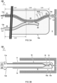
- FIGs 4A - 4B illustrate further aspects of example probe heads 10a in embodiments of the fibre endoscope system. While the figures show preferably multi-clad fiber configurations such as FIG 3B , in principle also single-clad fibers may be used such as FIG 2B .
- the probe head 10a includes a focusing optics 16 configured to focus illumination light Li from the third fiber ending 13a of the sampling fiber 13, e.g. the fiber core, onto the sample region S and/or collecting sample light Ls from the sample region S back onto the third fiber ending 13a, e.g. the first fiber cladding.
- a focusing optics 16 configured to focus illumination light Li from the third fiber ending 13a of the sampling fiber 13, e.g. the fiber core, onto the sample region S and/or collecting sample light Ls from the sample region S back onto the third fiber ending 13a, e.g. the first fiber cladding.
- the focusing optics 16 comprises a lens forming a front light exit port of the probe head 10a. While a traditional lens is shown, alternatively or additionally a gradient index lens (GRIN) is used. Instead of the lens forming the exit port, the lens can also be disposed elsewhere, e.g. inside the probe head 10a. For example, the exit port can be simply formed by a transparent material of the probe head 10a. Also other types of focusing optics 16 can be used such as curved mirrors, or the focusing optics 16 can be omitted for some applications. While the embodiment shows light exiting a front distal part of the probe head, light can also be directed to the side of the probe head.
- GRIN gradient index lens
- the probe head 10a includes an actuator 17 configured to vary the position of the illuminated spot on the sample region S, e.g. with a reciprocating, rotating, or other periodic motion.
- the third fiber ending 13a of the sampling fiber 13 itself is moved, e.g. in a reciprocating motion using a piezo actuator integrated into the probe head 10a.
- the light beam is redirected between the third fiber ending 13a and the sample region S, e.g. in a rotating or reciprocating motion using a micro-motor with rotating mirror or other beam redirection means integrated into the probe head, e.g. according to FIG 4C or 4D .
- electrical wiring 17w may be included inside the catheter 10 together with the optical fibers.
- control can be automatic and/or a local power source such as battery may be used.
- an optically-driven motor is used, e.g. wherein the cladding may act as a source or conduit of radiation for a photovoltaic cell powering the motor.
- externally driven motors e.g. with varying magnetic fields, can be envisaged.
- the focusing optics 16 may be separate from the actuator 17, as shown in FIGs 4B and 4C , or they can be integrated, as shown in FIG 4D .
- the actuator 17 may rotate a curved mirror to sweep an area of the sample region S around the probe head 10a.
Landscapes
- Health & Medical Sciences (AREA)
- Life Sciences & Earth Sciences (AREA)
- Physics & Mathematics (AREA)
- Surgery (AREA)
- Optics & Photonics (AREA)
- Biomedical Technology (AREA)
- Public Health (AREA)
- Veterinary Medicine (AREA)
- Pathology (AREA)
- Heart & Thoracic Surgery (AREA)
- General Health & Medical Sciences (AREA)
- Engineering & Computer Science (AREA)
- Animal Behavior & Ethology (AREA)
- Biophysics (AREA)
- Molecular Biology (AREA)
- Medical Informatics (AREA)
- Radiology & Medical Imaging (AREA)
- Nuclear Medicine, Radiotherapy & Molecular Imaging (AREA)
- General Physics & Mathematics (AREA)
- Astronomy & Astrophysics (AREA)
- Endoscopes (AREA)
- Instruments For Viewing The Inside Of Hollow Bodies (AREA)
- Investigating, Analyzing Materials By Fluorescence Or Luminescence (AREA)
Claims (15)
- Faserendoskopsystem (100), umfassend- einen Katheter (10) mit einem Sondenkopf (10a) zum Eintritt in eine Körperhöhle, einen Kanal oder ein Gefäß (C) neben einem zu messenden Probenbereich (S);- eine Quellfaser (11) mit einem ersten Faserende (11a), das vom Sondenkopf (10a) entfernt ist;- eine Signalfaser (12) mit einem zweiten Faserende (12a), das ebenfalls vom Sondenkopf (10a) entfernt, aber von der Quellfaser (11) getrennt ist;- eine Abtastfaser (13) mit einem dritten Faserende (13a), die am Sondenkopf (10a) angeordnet ist; und- einen Faserkoppler (15);
dadurch gekennzeichnet, dass der Faserkoppler (15) dazu eingerichtet ist, wenigstenso die Quellfaser (11) zur Abtastfaser (13), undo die Abtastfaser (13) zur Signalfaser (12) zu koppeln;- wobei eine Abtastfaserlänge (L13) der Abtastfaser (13) zwischen dem Faserkoppler (15) und dem dritten Faserende (13a) um wenigstens einen Faktor zwei kürzer ist als eine Quellfaserlänge (L11) der Quellfaser (11) zwischen dem Faserkoppler (15) und dem ersten Faserende (11a). - System nach Anspruch 1, wobei die Abtastfaser (13) eine mehrfach ummantelte Faser ist, die wenigstens einen Faserkern (1) mit einem ersten Fasermantel (2) um den Faserkern (1) und einem zweiten Fasermantel (3) um den ersten Fasermantel (2) umfasst; wobei der Faserkoppler (15) so eingerichtet ist, dass er wenigstenso die Quellfaser (11) zum Faserkern (1) der Abtastfaser (13), undo den ersten Fasermantel (2) der Abtastfaser (13) zur Signalfaser (12) koppelt.
- System nach einem der vorhergehenden Ansprüche, wobei die Abtastfaserlänge (L13) weniger als fünf Zentimeter und die Quellfaserlänge (L11) mehr als einen Meter beträgt.
- System nach einem der vorhergehenden Ansprüche, wobei der Faserkoppler (15) im Sondenkopf (10a) an einem distalen Ende des Katheters (10) angeordnet ist.
- System nach einem der vorhergehenden Ansprüche, wobei der Faserkoppler (15) verhältnismäßig biegsam ist und eine Biegesteifigkeit von weniger als einem Gigapascal aufweist.
- System nach einem der vorhergehenden Ansprüche, wobei das Faserendoskopsystem (100) einen optischen Interrogator aufweist, der dazu eingerichtet ist, Eingangslicht (Li') in das erste Faserende (11a) der Quellfaser (11) zu lenken und Signallicht (Ls') von dem zweiten Faserende (12a) der Signalfaser (12) zu empfangen.
- System nach einem der vorhergehenden Ansprüche, wobei die Abtastfaser (13) eine doppelt ummantelte Faser (DCF) ist, wobei der erste Fasermantel (2) einen inneren Mantel der doppelt ummantelten Faser bildet, die von einem zweiten Fasermantel (3) umgeben ist, die einen äußeren Mantelung der doppelt ummantelten Faser (DCF) bildet.
- System nach einem der vorhergehenden Ansprüche, wobei der Faserkoppler (15) ein asymmetrischer, mehrfach ummantelter Faserkoppler ist, wobei sich ein Faserkern (1) durch den Koppler zwischen der Quellfaser (11) und der Abtastfaser (13) erstreckt.
- System nach einem der vorhergehenden Ansprüche, wobei ein Faserkern (1) der Abtastfaser (13) so eingerichtet ist, dass er den Probenbereich (S) beleuchtet, wobei das Beleuchtungslicht (Li) den Faserkern (1) an dem dritten Faserende (13a) verlässt, das am Sondenkopf (10a) angeordnet ist, nachdem es in das erste Faserende (11a) der Quellfaser (11) als Eingangslicht (Li') eingetreten ist, das vom Sondenkopf (10a) entfernt ist.
- System nach einem der vorhergehenden Ansprüche, wobei ein erster Fasermantel (2) der Abtastfaser (13) dazu eingerichtet ist, Probenlicht (Ls) aus dem beleuchteten Probenbereich (S) zu sammeln und wenigstens einen Teil des gesammelten Probenlichts (Ls) über den Faserkoppler (15) in die Signalfaser (12) zu übertragen, um die Signalfaser (12) als Signallicht (Ls') zu verlassen.
- System nach einem der vorhergehenden Ansprüche, wobei der Sondenkopf (10a) eine Fokussieroptik (16) einschließt, die so eingerichtet ist, dass sie das Beleuchtungslicht (Li) von dem dritten Faserende (13a) der Abtastfaser (13) auf den Probenbereich (S) fokussiert und/oder das Probenlicht (Ls) vom Probenbereich (S) zurück auf das dritte Faserende (13a) sammelt.
- System nach einem der vorhergehenden Ansprüche, wobei ein Aktuator (17) in den Sondenkopf (10a) integriert ist und so eingerichtet ist, dass er die Position eines beleuchteten Punkts auf dem Probenbereich (S) mit einer hin- und hergehenden oder rotierenden Bewegung variiert.
- System nach einem der vorhergehenden Ansprüche, wobei ein Lichtstrahl zwischen dem dritten Faserende (13a) und dem Probenbereich (S) in einer rotierenden oder hin- und hergehenden Bewegung unter Verwendung eines Mikromotors mit rotierendem Spiegel oder einem anderen in den Sondenkopf (10a) integrierten Strahlumlenkungsmittel umgelenkt wird.
- System nach einem der vorhergehenden Ansprüche, wobei der Sondenkopf (10a) einen Aktuator (17) einschließt, der so eingerichtet ist, dass er eine Fokussieroptik (16) bewegt, um einen Lichtstrahl vom dritten Faserende (13a) auf den Probenbereich (S) umzuleiten und zu fokussieren.
- System nach einem der vorhergehenden Ansprüche, wobei das dritte Faserende (13a) der Abtastfaser (13) selbst durch einen in den Sondenkopf (10a) integrierten Aktuator bewegt wird.
Applications Claiming Priority (2)
| Application Number | Priority Date | Filing Date | Title |
|---|---|---|---|
| NL2020692A NL2020692B1 (en) | 2018-03-29 | 2018-03-29 | Fiber endoscope |
| PCT/NL2019/050193 WO2019190321A1 (en) | 2018-03-29 | 2019-03-28 | Fiber endoscope |
Publications (3)
| Publication Number | Publication Date |
|---|---|
| EP3773163A1 EP3773163A1 (de) | 2021-02-17 |
| EP3773163B1 true EP3773163B1 (de) | 2023-08-30 |
| EP3773163C0 EP3773163C0 (de) | 2023-08-30 |
Family
ID=62134195
Family Applications (1)
| Application Number | Title | Priority Date | Filing Date |
|---|---|---|---|
| EP19720190.8A Active EP3773163B1 (de) | 2018-03-29 | 2019-03-28 | Faserendoskop |
Country Status (4)
| Country | Link |
|---|---|
| US (1) | US11963663B2 (de) |
| EP (1) | EP3773163B1 (de) |
| NL (1) | NL2020692B1 (de) |
| WO (1) | WO2019190321A1 (de) |
Family Cites Families (12)
| Publication number | Priority date | Publication date | Assignee | Title |
|---|---|---|---|---|
| IT1213864B (it) * | 1987-12-23 | 1990-01-05 | Consiglio Nazionale Ricerche | Metodo di rilevamento del reflusso enterogastrico ed attrezzatura per l'attuazione di detto metodo |
| US6006119A (en) * | 1998-02-04 | 1999-12-21 | Polestar Technologies, Inc. | Non-invasive optical measurement of blood hematocrit |
| WO2008052153A2 (en) * | 2006-10-26 | 2008-05-02 | Cornell Research Foundation, Inc. | Production of optical pulses at a desired wavelength using soliton self-frequency shift |
| US9566030B2 (en) * | 2007-02-01 | 2017-02-14 | Ls Biopath, Inc. | Optical system for detection and characterization of abnormal tissue and cells |
| US9332942B2 (en) * | 2008-01-28 | 2016-05-10 | The General Hospital Corporation | Systems, processes and computer-accessible medium for providing hybrid flourescence and optical coherence tomography imaging |
| EP2288948A4 (de) * | 2008-06-20 | 2011-12-28 | Gen Hospital Corp | Anordnung aus kondensierten glasfaserkopplern und verfahren zu ihrer verwendung |
| CN102980658A (zh) * | 2012-11-14 | 2013-03-20 | 天津理工大学 | 一种微型光纤光谱仪 |
| US20170238807A9 (en) * | 2013-03-15 | 2017-08-24 | LX Medical, Inc. | Tissue imaging and image guidance in luminal anatomic structures and body cavities |
| US10401883B2 (en) * | 2018-01-11 | 2019-09-03 | Eric Swanson | Optical probe using multimode optical waveguide and proximal processing |
| US11156555B2 (en) * | 2018-01-25 | 2021-10-26 | Swinburne University Of Technology | Optical fibre based microprobe |
| WO2020113570A1 (zh) * | 2018-12-07 | 2020-06-11 | 深圳先进技术研究院 | 多模态胰胆管成像系统 |
| CN209712839U (zh) * | 2018-12-07 | 2019-12-03 | 深圳先进技术研究院 | 一种内窥导管装置 |
-
2018
- 2018-03-29 NL NL2020692A patent/NL2020692B1/en not_active IP Right Cessation
-
2019
- 2019-03-28 WO PCT/NL2019/050193 patent/WO2019190321A1/en not_active Ceased
- 2019-03-28 EP EP19720190.8A patent/EP3773163B1/de active Active
- 2019-03-28 US US17/042,488 patent/US11963663B2/en active Active
Also Published As
| Publication number | Publication date |
|---|---|
| WO2019190321A1 (en) | 2019-10-03 |
| NL2020692B1 (en) | 2019-10-07 |
| EP3773163A1 (de) | 2021-02-17 |
| US11963663B2 (en) | 2024-04-23 |
| US20210022590A1 (en) | 2021-01-28 |
| EP3773163C0 (de) | 2023-08-30 |
Similar Documents
| Publication | Publication Date | Title |
|---|---|---|
| US20220221708A1 (en) | Optical Instrument for Imaging and Sensing using Multicore Fiber | |
| Lee et al. | Scanning fiber endoscopy with highly flexible, 1 mm catheterscopes for wide‐field, full‐color imaging | |
| US8705184B2 (en) | Multi-path, multi-magnification, non-confocal fluorescence emission endoscopy apparatus and methods | |
| Kučikas et al. | Two-photon endoscopy: state of the art and perspectives | |
| US8842208B2 (en) | Optical fiber scanning probe | |
| US8553337B2 (en) | Multi-path, multi-magnification, non-confocal fluorescence emission endoscopy apparatus and methods | |
| US20130324858A1 (en) | Multi-path, multi-magnification, non-confocal fluorescence emission endoscopy apparatus and methods | |
| US20070213618A1 (en) | Scanning fiber-optic nonlinear optical imaging and spectroscopy endoscope | |
| Liang et al. | Throughput-speed product augmentation for scanning fiber-optic two-photon endomicroscopy | |
| JP2011508889A (ja) | 光学プローブ | |
| US9155474B2 (en) | System for multispectral imaging of fluorescence | |
| US10736489B2 (en) | Endoscope having an optical waveguide with emergence portion and an objective with beam splitter | |
| KR101258682B1 (ko) | 내시경과 일체형으로 제작된 광섬유쌍 프로브 이미징 시스템 | |
| Kim et al. | Objective-lens-free confocal endomicroscope using Lissajous scanning lensed-fiber | |
| US9131845B2 (en) | Optical probe | |
| EP3773163B1 (de) | Faserendoskop | |
| EP4185902B1 (de) | Optisches element | |
| CN118541071A (zh) | 一种扫描光纤内镜探头和扫描光纤内镜 | |
| KR101911352B1 (ko) | 다중 형광 검출 장치 | |
| US20240268674A1 (en) | Illumination system and medical imaging system for fluorescence imaging in open surgery | |
| Malekoshoaraie et al. | Microimager: a flexible thin-film miniaturized endoscope for optical biomedical imaging | |
| Chamot et al. | MEMS for enhanced optical diagnostics in endoscopy | |
| Tkaczyk | Endomicroscopy | |
| Murukeshan | Biomedical fiber optics | |
| Vega et al. | Model and evaluation of face forward illumination for multimodal endoscopic probes |
Legal Events
| Date | Code | Title | Description |
|---|---|---|---|
| STAA | Information on the status of an ep patent application or granted ep patent |
Free format text: STATUS: UNKNOWN |
|
| STAA | Information on the status of an ep patent application or granted ep patent |
Free format text: STATUS: THE INTERNATIONAL PUBLICATION HAS BEEN MADE |
|
| PUAI | Public reference made under article 153(3) epc to a published international application that has entered the european phase |
Free format text: ORIGINAL CODE: 0009012 |
|
| STAA | Information on the status of an ep patent application or granted ep patent |
Free format text: STATUS: REQUEST FOR EXAMINATION WAS MADE |
|
| 17P | Request for examination filed |
Effective date: 20201020 |
|
| AK | Designated contracting states |
Kind code of ref document: A1 Designated state(s): AL AT BE BG CH CY CZ DE DK EE ES FI FR GB GR HR HU IE IS IT LI LT LU LV MC MK MT NL NO PL PT RO RS SE SI SK SM TR |
|
| AX | Request for extension of the european patent |
Extension state: BA ME |
|
| DAV | Request for validation of the european patent (deleted) | ||
| DAX | Request for extension of the european patent (deleted) | ||
| GRAP | Despatch of communication of intention to grant a patent |
Free format text: ORIGINAL CODE: EPIDOSNIGR1 |
|
| STAA | Information on the status of an ep patent application or granted ep patent |
Free format text: STATUS: GRANT OF PATENT IS INTENDED |
|
| INTG | Intention to grant announced |
Effective date: 20211206 |
|
| GRAJ | Information related to disapproval of communication of intention to grant by the applicant or resumption of examination proceedings by the epo deleted |
Free format text: ORIGINAL CODE: EPIDOSDIGR1 |
|
| STAA | Information on the status of an ep patent application or granted ep patent |
Free format text: STATUS: REQUEST FOR EXAMINATION WAS MADE |
|
| GRAP | Despatch of communication of intention to grant a patent |
Free format text: ORIGINAL CODE: EPIDOSNIGR1 |
|
| STAA | Information on the status of an ep patent application or granted ep patent |
Free format text: STATUS: GRANT OF PATENT IS INTENDED |
|
| INTC | Intention to grant announced (deleted) | ||
| INTG | Intention to grant announced |
Effective date: 20220513 |
|
| GRAJ | Information related to disapproval of communication of intention to grant by the applicant or resumption of examination proceedings by the epo deleted |
Free format text: ORIGINAL CODE: EPIDOSDIGR1 |
|
| STAA | Information on the status of an ep patent application or granted ep patent |
Free format text: STATUS: REQUEST FOR EXAMINATION WAS MADE |
|
| GRAP | Despatch of communication of intention to grant a patent |
Free format text: ORIGINAL CODE: EPIDOSNIGR1 |
|
| STAA | Information on the status of an ep patent application or granted ep patent |
Free format text: STATUS: GRANT OF PATENT IS INTENDED |
|
| INTC | Intention to grant announced (deleted) | ||
| INTG | Intention to grant announced |
Effective date: 20221020 |
|
| GRAJ | Information related to disapproval of communication of intention to grant by the applicant or resumption of examination proceedings by the epo deleted |
Free format text: ORIGINAL CODE: EPIDOSDIGR1 |
|
| STAA | Information on the status of an ep patent application or granted ep patent |
Free format text: STATUS: REQUEST FOR EXAMINATION WAS MADE |
|
| GRAP | Despatch of communication of intention to grant a patent |
Free format text: ORIGINAL CODE: EPIDOSNIGR1 |
|
| STAA | Information on the status of an ep patent application or granted ep patent |
Free format text: STATUS: GRANT OF PATENT IS INTENDED |
|
| INTC | Intention to grant announced (deleted) | ||
| INTG | Intention to grant announced |
Effective date: 20230313 |
|
| GRAS | Grant fee paid |
Free format text: ORIGINAL CODE: EPIDOSNIGR3 |
|
| GRAA | (expected) grant |
Free format text: ORIGINAL CODE: 0009210 |
|
| STAA | Information on the status of an ep patent application or granted ep patent |
Free format text: STATUS: THE PATENT HAS BEEN GRANTED |
|
| AK | Designated contracting states |
Kind code of ref document: B1 Designated state(s): AL AT BE BG CH CY CZ DE DK EE ES FI FR GB GR HR HU IE IS IT LI LT LU LV MC MK MT NL NO PL PT RO RS SE SI SK SM TR |
|
| REG | Reference to a national code |
Ref country code: GB Ref legal event code: FG4D |
|
| REG | Reference to a national code |
Ref country code: CH Ref legal event code: EP |
|
| REG | Reference to a national code |
Ref country code: DE Ref legal event code: R096 Ref document number: 602019036109 Country of ref document: DE |
|
| REG | Reference to a national code |
Ref country code: IE Ref legal event code: FG4D |
|
| U01 | Request for unitary effect filed |
Effective date: 20230928 |
|
| U07 | Unitary effect registered |
Designated state(s): AT BE BG DE DK EE FI FR IT LT LU LV MT NL PT SE SI Effective date: 20231006 |
|
| PG25 | Lapsed in a contracting state [announced via postgrant information from national office to epo] |
Ref country code: GR Free format text: LAPSE BECAUSE OF FAILURE TO SUBMIT A TRANSLATION OF THE DESCRIPTION OR TO PAY THE FEE WITHIN THE PRESCRIBED TIME-LIMIT Effective date: 20231201 |
|
| PG25 | Lapsed in a contracting state [announced via postgrant information from national office to epo] |
Ref country code: IS Free format text: LAPSE BECAUSE OF FAILURE TO SUBMIT A TRANSLATION OF THE DESCRIPTION OR TO PAY THE FEE WITHIN THE PRESCRIBED TIME-LIMIT Effective date: 20231230 |
|
| PG25 | Lapsed in a contracting state [announced via postgrant information from national office to epo] |
Ref country code: RS Free format text: LAPSE BECAUSE OF FAILURE TO SUBMIT A TRANSLATION OF THE DESCRIPTION OR TO PAY THE FEE WITHIN THE PRESCRIBED TIME-LIMIT Effective date: 20230830 Ref country code: NO Free format text: LAPSE BECAUSE OF FAILURE TO SUBMIT A TRANSLATION OF THE DESCRIPTION OR TO PAY THE FEE WITHIN THE PRESCRIBED TIME-LIMIT Effective date: 20231130 Ref country code: IS Free format text: LAPSE BECAUSE OF FAILURE TO SUBMIT A TRANSLATION OF THE DESCRIPTION OR TO PAY THE FEE WITHIN THE PRESCRIBED TIME-LIMIT Effective date: 20231230 Ref country code: HR Free format text: LAPSE BECAUSE OF FAILURE TO SUBMIT A TRANSLATION OF THE DESCRIPTION OR TO PAY THE FEE WITHIN THE PRESCRIBED TIME-LIMIT Effective date: 20230830 Ref country code: GR Free format text: LAPSE BECAUSE OF FAILURE TO SUBMIT A TRANSLATION OF THE DESCRIPTION OR TO PAY THE FEE WITHIN THE PRESCRIBED TIME-LIMIT Effective date: 20231201 |
|
| U20 | Renewal fee for the european patent with unitary effect paid |
Year of fee payment: 6 Effective date: 20240123 |
|
| PG25 | Lapsed in a contracting state [announced via postgrant information from national office to epo] |
Ref country code: PL Free format text: LAPSE BECAUSE OF FAILURE TO SUBMIT A TRANSLATION OF THE DESCRIPTION OR TO PAY THE FEE WITHIN THE PRESCRIBED TIME-LIMIT Effective date: 20230830 |
|
| PG25 | Lapsed in a contracting state [announced via postgrant information from national office to epo] |
Ref country code: ES Free format text: LAPSE BECAUSE OF FAILURE TO SUBMIT A TRANSLATION OF THE DESCRIPTION OR TO PAY THE FEE WITHIN THE PRESCRIBED TIME-LIMIT Effective date: 20230830 |
|
| PG25 | Lapsed in a contracting state [announced via postgrant information from national office to epo] |
Ref country code: SM Free format text: LAPSE BECAUSE OF FAILURE TO SUBMIT A TRANSLATION OF THE DESCRIPTION OR TO PAY THE FEE WITHIN THE PRESCRIBED TIME-LIMIT Effective date: 20230830 Ref country code: RO Free format text: LAPSE BECAUSE OF FAILURE TO SUBMIT A TRANSLATION OF THE DESCRIPTION OR TO PAY THE FEE WITHIN THE PRESCRIBED TIME-LIMIT Effective date: 20230830 Ref country code: ES Free format text: LAPSE BECAUSE OF FAILURE TO SUBMIT A TRANSLATION OF THE DESCRIPTION OR TO PAY THE FEE WITHIN THE PRESCRIBED TIME-LIMIT Effective date: 20230830 Ref country code: CZ Free format text: LAPSE BECAUSE OF FAILURE TO SUBMIT A TRANSLATION OF THE DESCRIPTION OR TO PAY THE FEE WITHIN THE PRESCRIBED TIME-LIMIT Effective date: 20230830 Ref country code: SK Free format text: LAPSE BECAUSE OF FAILURE TO SUBMIT A TRANSLATION OF THE DESCRIPTION OR TO PAY THE FEE WITHIN THE PRESCRIBED TIME-LIMIT Effective date: 20230830 |
|
| REG | Reference to a national code |
Ref country code: DE Ref legal event code: R097 Ref document number: 602019036109 Country of ref document: DE |
|
| PLBE | No opposition filed within time limit |
Free format text: ORIGINAL CODE: 0009261 |
|
| STAA | Information on the status of an ep patent application or granted ep patent |
Free format text: STATUS: NO OPPOSITION FILED WITHIN TIME LIMIT |
|
| 26N | No opposition filed |
Effective date: 20240603 |
|
| REG | Reference to a national code |
Ref country code: CH Ref legal event code: PL |
|
| PG25 | Lapsed in a contracting state [announced via postgrant information from national office to epo] |
Ref country code: MC Free format text: LAPSE BECAUSE OF FAILURE TO SUBMIT A TRANSLATION OF THE DESCRIPTION OR TO PAY THE FEE WITHIN THE PRESCRIBED TIME-LIMIT Effective date: 20230830 |
|
| GBPC | Gb: european patent ceased through non-payment of renewal fee |
Effective date: 20240328 |
|
| PG25 | Lapsed in a contracting state [announced via postgrant information from national office to epo] |
Ref country code: MC Free format text: LAPSE BECAUSE OF FAILURE TO SUBMIT A TRANSLATION OF THE DESCRIPTION OR TO PAY THE FEE WITHIN THE PRESCRIBED TIME-LIMIT Effective date: 20230830 |
|
| PG25 | Lapsed in a contracting state [announced via postgrant information from national office to epo] |
Ref country code: GB Free format text: LAPSE BECAUSE OF NON-PAYMENT OF DUE FEES Effective date: 20240328 |
|
| PG25 | Lapsed in a contracting state [announced via postgrant information from national office to epo] |
Ref country code: IE Free format text: LAPSE BECAUSE OF NON-PAYMENT OF DUE FEES Effective date: 20240328 |
|
| PG25 | Lapsed in a contracting state [announced via postgrant information from national office to epo] |
Ref country code: IE Free format text: LAPSE BECAUSE OF NON-PAYMENT OF DUE FEES Effective date: 20240328 Ref country code: GB Free format text: LAPSE BECAUSE OF NON-PAYMENT OF DUE FEES Effective date: 20240328 Ref country code: CH Free format text: LAPSE BECAUSE OF NON-PAYMENT OF DUE FEES Effective date: 20240331 |
|
| U20 | Renewal fee for the european patent with unitary effect paid |
Year of fee payment: 7 Effective date: 20250218 |
|
| PG25 | Lapsed in a contracting state [announced via postgrant information from national office to epo] |
Ref country code: CY Free format text: LAPSE BECAUSE OF FAILURE TO SUBMIT A TRANSLATION OF THE DESCRIPTION OR TO PAY THE FEE WITHIN THE PRESCRIBED TIME-LIMIT; INVALID AB INITIO Effective date: 20190328 |
|
| PG25 | Lapsed in a contracting state [announced via postgrant information from national office to epo] |
Ref country code: HU Free format text: LAPSE BECAUSE OF FAILURE TO SUBMIT A TRANSLATION OF THE DESCRIPTION OR TO PAY THE FEE WITHIN THE PRESCRIBED TIME-LIMIT; INVALID AB INITIO Effective date: 20190328 |
|
| PG25 | Lapsed in a contracting state [announced via postgrant information from national office to epo] |
Ref country code: TR Free format text: LAPSE BECAUSE OF FAILURE TO SUBMIT A TRANSLATION OF THE DESCRIPTION OR TO PAY THE FEE WITHIN THE PRESCRIBED TIME-LIMIT Effective date: 20230830 |