EP3773171B1 - Systeme und verfahren zur massenbewegungskompensation in der phasenbasierten optischen kohärenztomografie - Google Patents
Systeme und verfahren zur massenbewegungskompensation in der phasenbasierten optischen kohärenztomografie Download PDFInfo
- Publication number
- EP3773171B1 EP3773171B1 EP19782157.2A EP19782157A EP3773171B1 EP 3773171 B1 EP3773171 B1 EP 3773171B1 EP 19782157 A EP19782157 A EP 19782157A EP 3773171 B1 EP3773171 B1 EP 3773171B1
- Authority
- EP
- European Patent Office
- Prior art keywords
- oct
- bulk motion
- variance values
- scan
- complex
- Prior art date
- Legal status (The legal status is an assumption and is not a legal conclusion. Google has not performed a legal analysis and makes no representation as to the accuracy of the status listed.)
- Active
Links
Images



Classifications
-
- A—HUMAN NECESSITIES
- A61—MEDICAL OR VETERINARY SCIENCE; HYGIENE
- A61B—DIAGNOSIS; SURGERY; IDENTIFICATION
- A61B3/00—Apparatus for testing the eyes; Instruments for examining the eyes
- A61B3/0016—Operational features thereof
- A61B3/0025—Operational features thereof characterised by electronic signal processing, e.g. eye models
-
- A—HUMAN NECESSITIES
- A61—MEDICAL OR VETERINARY SCIENCE; HYGIENE
- A61B—DIAGNOSIS; SURGERY; IDENTIFICATION
- A61B3/00—Apparatus for testing the eyes; Instruments for examining the eyes
- A61B3/10—Objective types, i.e. instruments for examining the eyes independent of the patients' perceptions or reactions
- A61B3/102—Objective types, i.e. instruments for examining the eyes independent of the patients' perceptions or reactions for optical coherence tomography [OCT]
-
- A—HUMAN NECESSITIES
- A61—MEDICAL OR VETERINARY SCIENCE; HYGIENE
- A61B—DIAGNOSIS; SURGERY; IDENTIFICATION
- A61B5/00—Measuring for diagnostic purposes; Identification of persons
- A61B5/0059—Measuring for diagnostic purposes; Identification of persons using light, e.g. diagnosis by transillumination, diascopy, fluorescence
- A61B5/0062—Arrangements for scanning
- A61B5/0066—Optical coherence imaging
-
- A—HUMAN NECESSITIES
- A61—MEDICAL OR VETERINARY SCIENCE; HYGIENE
- A61B—DIAGNOSIS; SURGERY; IDENTIFICATION
- A61B5/00—Measuring for diagnostic purposes; Identification of persons
- A61B5/72—Signal processing specially adapted for physiological signals or for diagnostic purposes
- A61B5/7203—Signal processing specially adapted for physiological signals or for diagnostic purposes for noise prevention, reduction or removal
- A61B5/7207—Signal processing specially adapted for physiological signals or for diagnostic purposes for noise prevention, reduction or removal of noise induced by motion artifacts
Definitions
- the field involves methods of imaging using optical coherence tomography.
- the field involves methods of bulk motion compensation in phase-based functional optical coherence tomography.
- OCT optical Coherence tomography
- Doppler OCT detects the phase shift between adjacent A-scans to provide flow velocity along the axial direction within the macrovasculature.
- OTA OCT angiography
- OCTA was developed to extract intrinsic blood flow signal within the microvasculature by subtracting the OCT signal of adjacent B-scans acquired at the same position.
- OCTA algorithms based on amplitude or phase signals have been successfully adopted by commercial systems and are routinely used by clinicians for ocular imaging.
- phase-based functional OCT e.g., phase-resolved Doppler OCT, phase-based OCTA
- phase-based OCTA phase-based OCTA
- phase-based methods are more vulnerable to bulk-motion artifacts than amplitude-based methods, so the step to remove bulk-motion phase shift is essential for accurately detecting the flow signal.
- phase compensation methods Two phase compensation methods have been previously reported and widely used.
- One is the "average” method, which estimates bulk-motion phase shift by averaging the phase shift along each A-line in the B-frame within the retinal tissue slab. This method may introduce a large error when vessels and their shadows occupy a relative large portion of tissue.
- the other is the “histogram” method, which estimates this artifact by finding the phase shift with the highest bin number (peak density) in the histogram of all values crossing the tissue on each A-line.
- the "histogram” method can be more accurate than the "average” method by iteratively subtracting estimated bulk-motion phase shift on each A-line. However, it requires a large computational budget. Thus, there remains a need for a fast and robust method for bulk motion compensation in phase-based functional OCT.
- US2014/236002 discloses A system and method for measuring tissue motion within a living tissue of the anterior segment and aqueous outflow system of the eye in a subject. Tissue movements are extracted from a plurality of images acquired from the living tissue using an optical coherence tomography system. The images may be corrected using motion compensation. To extract the tissue movements from the images, waves from a cardiac pulse or other externally induced pulses from the subject are acquired, and a pulse wave is defined for a given time, which is then correlated with a velocity wave defined for a velocity of tissue and/or fluid movement within the tissue region for the same given time. Pulsatile motion is then isolated in the tissue region from the plurality of images.
- the disclosed methods and systems are based on the use of the standard deviation of the phase shift signal present in phase-based OCT imaging.
- the disclosed systems and methods are applicable to complex-valued signals, such as OCT signals having both amplitude and phase information.
- the disclosed methods and systems are applicable to phase-based functional OCT imaging applications.
- functional OCT imaging include retinal Doppler OCT, OCT angiography (OCTA), and OCT elastography.
- An aspect of the disclosed methods and systems is that they provide robust and computationally efficient approaches for bulk motion compensation in phase-based functional OCT imaging. Compared to other bulk-motion compensation methods known in the art, the disclosed methods provide improvements in image quality with reduced processing time.
- the exemplary system comprises an OCT device configured to acquire OCT structural and angiography data in functional connection with a computing device having a logic subsystem and data holding capabilities.
- the computing device is configured to receive data from the OCT device and perform one or more operations of the methods described herein.
- structure and/or flow information of a sample can be obtained using OCT (structure) and OCT angiography (flow) imaging-based on the detection of spectral interference.
- OCT structure
- flow OCT angiography
- imaging can be two-dimensional (2-D) or three-dimensional (3-D), depending on the application.
- Structural imaging can be of an extended depth range relative to prior art methods, and flow imaging can be performed in real time.
- One or both of structural imaging and flow imaging as disclosed herein can be enlisted for producing 2-D or 3-D images.
- A-scan A reflectivity profile that contains information about spatial dimensions and location of structures within an item of interest.
- An A-scan is an axial scan directed along the optical axis of the OCT device and penetrates the sample being imaged.
- the A-scan encodes reflectivity information (for example, signal intensity) as a function of depth (z-direction).
- B-scan A cross-sectional tomograph that can be achieved by laterally combining a series of axial depth scans (i.e., A-scans) in the x-direction or y-direction.
- a B-scan encodes planar cross-sectional information from the sample and is typically presented as an image.
- a B-scan can be called a cross sectional image.
- a dataset is an ordered-array representation of stored data values that encodes relative spatial location in row-column-depth (x-y-z axes) format.
- a dataset can be conceptualized as a three dimensional array of voxels, each voxel having an associated value (for example, an intensity value, a complex value having both amplitude and phase information, a decorrelation value, or other signal representations).
- An A-scan corresponds to a set of collinear voxels along the depth (z-axis) direction of the dataset; a B-scan is made up of set of adjacent A-scans combined in the row or column (x- or y- axis) directions. Such a B-scan can also be referred to as an image, and its constituent voxels referred to as pixels. A collection of adjacent B-scans can be combined form a 3D volumetric set of voxel data referred to as a 3D image.
- the dataset obtained by an OCT scanning device is termed a "structural OCT" dataset whose values can, for example, be complex numbers carrying intensity and phase information.
- This structural OCT dataset can be used to calculate a corresponding dataset termed an "OCT angiography" dataset reflecting flow within the imaged sample.
- OCT angiography a corresponding dataset reflecting flow within the imaged sample.
- OCT angiography a corresponding dataset reflecting flow within the imaged sample.
- values from the datasets can be "overlaid” to present composite images of structure and flow (e.g., tissue microstructure and blood flow) or otherwise combined or compared.
- En Face angiogram OCT angiography data can be presented as a 2D projection of the three dimensional dataset onto a single planar image called an en face angiogram. Construction of such an en face angiogram requires the specification of the upper and lower depth extents that enclose the region of interest within the retina OCT scan to be projected onto the angiogram image. These upper and lower depth extents can be specified as the boundaries between different layers of the retina (e.g., the voxels between the inner limiting membrane and outer plexiform layer could be used to generate an en face angiogram of the inner retina). Once generated, the en face angiogram image may be used to quantify various features of the retinal vasculature as described herein.
- This quantification typically involves the setting of a threshold value to differentiate, for example, the pixels that represent flow within vasculature from static tissue within the angiogram.
- a threshold value to differentiate, for example, the pixels that represent flow within vasculature from static tissue within the angiogram.
- These en face angiograms can be interpreted in a manner similar to traditional angiography techniques such as fluorescein angiography (FA) or indocyanine green (ICG) angiography, and are thus well-suited for clinical use.
- FA fluorescein angiography
- ICG indocyanine green
- Functional OCT broadly refers to the extension of OCT techniques to provide information beyond structural characterization.
- structural OCT imaging may be used to gather spatial information about a tissue's anatomical organization
- functional OCT may be used to gather information about processes occurring within that tissue sample such as blood flow, tissue perfusion and oxygenation, birefringence, etc.
- Examples of functional OCT include, but are not limited to, OCT angiography (OCTA) and associated techniques for characterizing blood flow, Doppler OCT, polarization-sensitive OCT, OCT elastography, spectroscopic OCT, differential absorption OCT, and molecular imaging OCT.
- phase-based optical coherence tomography Phase-based OCT applications, such as OCT angiography (OCTA), Doppler OCT, and OCT elastography, are sensitive to the confounding phase shift introduced by subject bulk motion.
- Traditional bulk motion compensation methods are limited by their accuracy and computing cost-effectiveness.
- the novel bulk motion compensation method for phase-based functional OCT described herein offers advantages over traditional methods both in terms of improved image quality and decreased computational burden.
- Disclosed herein is a novel method of bulk motion compensation based on the standard deviation of OCT flow signals.
- An explicit equation of the bulk motion can be derived and subtracted from phase-based functional OCT.
- An aspect of the disclosed bulk motion compensation method is that it is more effective than previous averaging and histogram-based methods for reducing motion artifacts in OCT datasets. In addition, the method is less computationally intensive than these previous methods.
- the system modulation phase difference is assumed to be a constant for all A-scans and can be removed.
- the variance is a cosine function having phase ⁇ .
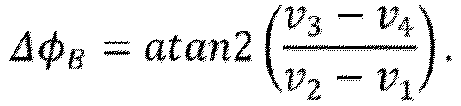
- the bulk motion phase ⁇ ⁇ B can be directly solved at variance values at four phase values ⁇ spaced at ⁇ /2 interval.
- v 1 std A n ⁇ A n + 1 2
- v 2 std A n ⁇ A n + 1 ⁇ exp ⁇ i ⁇ ⁇ 2
- v 3 std A n ⁇ A n + 1 ⁇ exp ⁇ i ⁇ ⁇ 2 2
- v 4 std A n ⁇ A n + 1 ⁇ exp ⁇ i ⁇ 3 ⁇ 2 2
- a n is the n th repeated A-line from the n th consecutive B-frames at the same location.
- the calculation accuracy of Eq. (14) can be increased by solving the equation multiple times by shifting the four sampling point values.
- Eq. (14) may be solved five times by shifting the four sampling points together with a random base phase ⁇ m (i.e., at ⁇ m , ⁇ m + ⁇ /2, ⁇ m + ⁇ and ⁇ m + 3 ⁇ /2).
- Five ⁇ ⁇ Bm may be calculated and averaged to obtain the final bulk motion phase shift ⁇ ⁇ B for each A-line.
- Other embodiments may use any suitable number of ⁇ ⁇ Bm values averaged together.
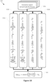
- FIG. 1A A flowchart illustrating a method 100 for bulk-motion compensation is shown in Figures 1A and 1B , in accordance with various embodiments described herein.
- the method 100 may be applied to OCTA scans.
- the method 100 may include a pre-calculation operation, as shown at 102 in Figure 1A .
- This pre-calculation operation 102 may include, for example, one or more signal processing operations to extract complex OCT signal data 104 from raw OCT spectrum data 106 (e.g., raw OCT spectrum data 106 subtracted by base spectrum 108 as shown at 110 of method 100).
- Such signal processing operations may include, but are not limited to, one or more operations for dispersion compensation, conversion from wavelength to frequency representation, wave number interpolation, and/or Fast Fourier Transform operations.
- bulk motion may then be estimated from complex OCT signal data 104 using a "standard deviation" method as described herein.
- one or more base phases e.g., ⁇ 1 , ⁇ 2 ,... ⁇ m
- the one or more base phases may be randomly selected, semi-randomly selected, or may be predetermined phase values.
- the phase difference ⁇ ⁇ Bm due to bulk motion may be determined for each base phase at 114a-c of the method 100.
- Figure 1B illustrates a method 150 of determining the phase difference ⁇ ⁇ Bm for a single base phase in more detail.
- the method 150 includes determining the variance values at four phase values spaced at ⁇ /2 interval relative to the base phase according to Equations (10)-(13) (noted as operations 152a-d in Figure 1B ).
- the bulk motion phase difference ⁇ ⁇ Bm for the given base phase is then determined at 154 of method 150 (e.g., according to Equation (14)).
- the bulk motion phase differences ⁇ ⁇ Bm for the multiple base phases may be averaged at 116 of method 100, to obtain a bulk motion phase shift ⁇ ⁇ B for each A-line.
- the averaging operation at 116 may be omitted when a single set of variance values at one base phase is used.
- individual A-lines of the OCT dataset may be adjusted based on the bulk motion phase shift ⁇ ⁇ B to obtain a bulk-motion compensated OCT dataset.
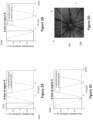
- the accuracy of the proposed method relies, in part, on how experimental results correlate with the cosine curve representation as predicted by Eq. (8). In other words, for results to be well-fit, it is necessary to retrieve an accurate bulk motion phase shift at the first lowest value of cosine function. To verify this was the case with experimental data, a single A-scan was randomly chosen from three different locations (one location in static tissue with capillaries only, and two locations in large vessels) within an OCT dataset of an in vivo rat eye. The relationship between the variances calculated at various ⁇ from data and the variance derived directly from Eq. (8) was investigated.
- Figures 2A-2C show plots of v vs ⁇ at three different points within the rat eye (denoted as region A, B, and C in Figure 2D ).
- the '+' marks on the plots are the calculated variances, normalized to -1 to 1.
- the curve 202a-c is the cosine function derived from the Eq. 8, the region 204a-c on the left side of each graph indicates the phase shift caused by bulk motion.
- the A-line chosen from a point that contains capillaries only while Figures 2B and 2C have A-lines chosen from points that contain large vessels.
- Figure 2D shows an en face OCT mean projection of a scan of a rat eye.
- Labelled position A, B, and C within Figure 2D correspond to plots of Figures 2A, 2B, and 2C .
- the high quality of the curve fits in Figures 2A, 2B, and 2C suggests that Eq. (8) is correct and that the bulk motion phase shift can be directly solved using Eq. (14).
- Retinal Doppler OCT and OCTA scans were acquired on rats to validate the disclosed systems and methods for bulk motion compensation.
- An exemplary prototype visible-light spectral-domain OCT system was used for imaging rodents. The system had a 50-kHz scanning rate, center wavelength at 560nm and axial resolution of 1.53 ⁇ m. All the experimental procedures were approved by the Institutional Animal Care and Use Committee (IACUC).
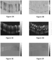
- Figures 3A-3F show representative data for an in vivo rat imaging experiment demonstrating the effectiveness of the disclosed methods for both OCTA and Doppler OCT applications.
- Cross-sectional OCT images were acquired from the same volumetric scan as shown in Figure 2D .
- An OCTA image was acquired at the position indicated by the horizontal line 206 in Figure 2D .
- a Doppler OCT image was acquired from the circular scan indicated by the circle 208 in Figure 2D .
- Figure 3A shows the phase difference image before bulk motion compensation, wherein the colored fringes indicate the bulk motion phase shift.
- Figure 3B shows the phase difference image after bulk motion compensation with the "standard deviation" (STD) method.
- Figure 3C shows the phase-based OCTA image without bulk motion compensation, where retinal flow signals are indistinguishable from motion artifact.
- Figure 3D shows the phase-based OCTA image after bulk motion compensation using the disclosed STD method, where true flow signals (indicated by yellow arrows) are rendered distinguishable.
- Figure 3E shows a Doppler OCT image before bulk motion compensation, where a large amount of motion signal and low Doppler signal contrast is present.
- Figure 3F shows the Doppler OCT image after bulk motion compensation with STD method, where Doppler signal contrast is improved.
- the range of color bars in Figures 3A, 3B, 3E, and 3F is the phase from - ⁇ to ⁇ .
- the range of color bars in Figures 3C and 3D is the normalized ampli
- the disclosed "standard deviation” method was also qualitatively and quantitatively evaluated on en face angiograms by comparing to two conventional methods - "average” and “histogram” methods - on the same dataset from a rat eye. To ensure a valid comparison between the three bulk-motion removal methods, all data were processed using the same operations with the exception of the phase compensation technique that was used.
- Retinal Doppler OCT and OCTA scans were acquired on humans to validate the disclosed systems and methods for bulk motion compensation.
- a commercial spectral-domain OCT system (RTVue-XR Avanti; Optovue, Inc., Fremont, CA) with 70-kHz scanning rate, center wavelength at 840 nm and an axial resolution of 5 um, was used for imaging the human retina.
- Written informed consent was obtained from all volunteers. All the experimental procedures were approved by the Institutional Review Board/Ethics Committee of OHSU.
- the disclosed "standard deviation” bulk-motion removal method was compared to conventional "average” and “histogram” methods by processing the same dataset using each method. Using enface angiograms, both qualitative and quantitative evaluations were made. To ensure a valid comparison between the three bulk-motion removal methods, all data were processed using the same signal processing operations in the workflow with the exception of the phase compensation technique that was used.
- the superficial vascular complex (SVC), intermediate capillary plexuses (ICP), and deep capillary plexuses (DCP) enface images were generated using custom automatic segmentation software.
- Figures 5A-5L shows the effect of different bulk motion compensation methods on en face maximum projection of flow in three different slabs (the SVC, ICP, and DCP).
- the three columns of Figures 5A-5L correspond to the three different slabs analyzed.
- the first column i.e., Figures 5A, 5D, 5G, and 5J
- the second column i.e., Figures 5B, 5E, 5H, and 5K
- ICP intermediate capillary plexus
- the third column i.e., Figures 5C, 5F, 5I, and 5L
- DCP deep capillary plexus
- Figures 5A-5L correspond to the four different bulk motion compensation methods applied.
- the first row ( Figures 5A-5C ) was calculated without bulk motion compensation (NONE)
- the second row ( Figures 5D-5F ) was calculated using the "average” (AVG) method
- the third row ( Figures 5G-5I ) was calculated using the "histogram” (HIST) method
- the fourth row ( Figures 5J-5L ) was calculated using the "standard deviation” (STD) method.
- STD standard deviation
- SNR flow signal to noise ratio
- Figure 6 is a graph showing the computational performance (or computational budget) of the three bulk motion removal calculations: the "average” method, the "histogram” method, and the disclosed “standard deviation” method.
- These computing platform used for this comparison was an Intel Core i7 6700k, 32GB RAM, single processing system with the methods implemented using Matlab 2017a (The Mathworks, Natick, MA).
- the "average” method had the lowest computational budget but also the lowest image quality.
- the "histogram” method had a higher image quality compared to the "average” method, but due to the required number of iterations, it had the highest computational budget.
- the “standard deviation” method had a relatively low computational budget as well as the best image quality.
- the “standard deviation” method for bulk motion calculation was almost 5 times faster than that of the "histogram” method.
- Figure 9 shows an exemplary procedure 900 for calculating bulk motion phase correction for OCTA and Doppler applications.
- complex OCT A-scan data A n and A n+1 are received.
- these two scans A n and A n +1 may be two repeated scans at the same location.
- these two scans may be two adjacent scans which may have some overlap.
- One of the scans is considered the reference OCT signal while the other scan is the signal having bulk motion that requires correction or compensation. For example, if the reference signal is designated as scan A n , its corresponding signal containing bulk motion that requires compensation is scan A n +1 .
- FIG. 7 schematically shows an example system 700 for OCT image processing in accordance with various embodiments.
- System 700 comprises an OCT system 702 configured to acquire an OCT image comprising OCT interferograms and one or more processors or computing systems 704 that are configured to implement the various processing routines described herein.
- OCT system 700 can comprise an OCT system suitable for structural OCT and OCT angiography applications, e.g., a swept source OCT system or spectral domain OCT system.
- an OCT system can be adapted to allow an operator to perform various tasks.
- an OCT system can be adapted to allow an operator to configure and/or launch various ones of the herein described methods.
- an OCT system can be adapted to generate, or cause to be generated, reports of various information including, for example, reports of the results of scans run on a sample.
- a display device can be adapted to receive an input (e.g., by a touch screen, actuation of an icon, manipulation of an input device such as a joystick or knob, etc.) and the input can, in some cases, be communicated (actively and/or passively) to one or more processors.
- data and/or information can be displayed, and an operator can input information in response thereto.
- the above described methods and processes can be tied to a computing system, including one or more computers.
- the methods and processes described herein e.g., the methods 100 depicted in Figure 1A and, the method 150 depicted in Figure 1B , and/or the procedure 900 depicted in Figure 9 , described above, can be implemented as a computer application, computer service, computer API, computer library, and/or other computer program product.
- FIG. 8 schematically shows a non-limiting computing device 800 that can perform one or more of the above described methods and processes.
- computing device 800 can represent a processor included in system 700 described above, and can be operatively coupled to, in communication with, or included in an OCT system or OCT image acquisition apparatus.
- Computing device 800 is shown in simplified form. It is to be understood that virtually any computer architecture can be used without departing from the scope of this disclosure.
- computing device 800 can take the form of a microcomputer, an integrated computer circuit, printed circuit board (PCB), microchip, a mainframe computer, server computer, desktop computer, laptop computer, tablet computer, home entertainment computer, network computing device, mobile computing device, mobile communication device, gaming device, etc.
- PCB printed circuit board
- Computing device 800 includes a logic subsystem 802 and a data-holding subsystem 804.
- Computing device 800 can optionally include a display subsystem 806, a communication subsystem 808, an imaging subsystem 810, and/or other components not shown in Figure 8 .
- Computing device 800 can also optionally include user input devices such as manually actuated buttons, switches, keyboards, mice, game controllers, cameras, microphones, and/or touch screens, for example.
- Logic subsystem 802 can include one or more physical devices configured to execute one or more machine-readable instructions.
- the logic subsystem can be configured to execute one or more instructions that are part of one or more applications, services, programs, routines, libraries, objects, components, data structures, or other logical constructs.
- Such instructions can be implemented to perform a task, implement a data type, transform the state of one or more devices, or otherwise arrive at a desired result.
- the logic subsystem can include one or more processors that are configured to execute software instructions.
- the one or more processors can comprise physical circuitry programmed to perform various acts described herein.
- the logic subsystem can include one or more hardware or firmware logic machines configured to execute hardware or firmware instructions.
- Processors of the logic subsystem can be single core or multicore, and the programs executed thereon can be configured for parallel or distributed processing.
- the logic subsystem can optionally include individual components that are distributed throughout two or more devices, which can be remotely located and/or configured for coordinated processing.
- One or more aspects of the logic subsystem can be virtualized and executed by remotely accessible networked computing devices configured in a cloud computing configuration.
- Data-holding subsystem 804 can include one or more physical, non-transitory, devices configured to hold data and/or instructions executable by the logic subsystem to implement the herein described methods and processes. When such methods and processes are implemented, the state of data-holding subsystem 804 can be transformed (e.g., to hold different data).
- Data-holding subsystem 804 can include removable media and/or built-in devices.
- Data-holding subsystem 804 can include optical memory devices (e.g., CD, DVD, HD-DVD, Blu-Ray Disc, etc.), semiconductor memory devices (e.g., RAM, EPROM, EEPROM, etc.) and/or magnetic memory devices (e.g., hard disk drive, floppy disk drive, tape drive, MRAM, etc.), among others.
- Data-holding subsystem 804 can include devices with one or more of the following characteristics: volatile, nonvolatile, dynamic, static, read/write, read-only, random access, sequential access, location addressable, file addressable, and content addressable.
- logic subsystem 802 and data-holding subsystem 804 can be integrated into one or more common devices, such as an application specific integrated circuit or a system on a chip.
- Figure 8 also shows an aspect of the data-holding subsystem in the form of removable computer-readable storage media 812, which can be used to store and/or transfer data and/or instructions executable to implement the herein described methods and processes.
- Removable computer-readable storage media 812 can take the form of CDs, DVDs, HD-DVDs, Blu-Ray Discs, EEPROMs, flash memory cards, USB storage devices, and/or floppy disks, among others.
- display subsystem 806 can be used to present a visual representation of data held by data-holding subsystem 804. As the herein described methods and processes change the data held by the data-holding subsystem, and thus transform the state of the data-holding subsystem, the state of display subsystem 806 can likewise be transformed to visually represent changes in the underlying data.
- Display subsystem 806 can include one or more display devices utilizing virtually any type of technology. Such display devices can be combined with logic subsystem 802 and/or data-holding subsystem 804 in a shared enclosure, or such display devices can be peripheral display devices.
- communication subsystem 808 can be configured to communicatively couple computing device 800 with one or more other computing devices.
- Communication subsystem 808 can include wired and/or wireless communication devices compatible with one or more different communication protocols.
- the communication subsystem can be configured for communication via a wireless telephone network, a wireless local area network, a wired local area network, a wireless wide area network, a wired wide area network, etc.
- the communication subsystem can allow computing device 800 to send and/or receive messages to and/or from other devices via a network such as the Internet.
- imaging subsystem 810 can be used acquire and/or process any suitable image data from various sensors or imaging devices in communication with computing device 800.
- imaging subsystem 810 can be configured to acquire OCT image data, e.g., interferograms, as part of an OCT system, e.g., OCT system 702 described above.
- Imaging subsystem 810 can be combined with logic subsystem 802 and/or data-holding subsystem 804 in a shared enclosure, or such imaging subsystems can comprise periphery imaging devices. Data received from the imaging subsystem can be held by data-holding subsystem 804 and/or removable computer-readable storage media 812, for example.
Landscapes
- Health & Medical Sciences (AREA)
- Life Sciences & Earth Sciences (AREA)
- Engineering & Computer Science (AREA)
- Biomedical Technology (AREA)
- Animal Behavior & Ethology (AREA)
- Biophysics (AREA)
- Veterinary Medicine (AREA)
- Public Health (AREA)
- General Health & Medical Sciences (AREA)
- Heart & Thoracic Surgery (AREA)
- Medical Informatics (AREA)
- Molecular Biology (AREA)
- Surgery (AREA)
- Physics & Mathematics (AREA)
- Nuclear Medicine, Radiotherapy & Molecular Imaging (AREA)
- Radiology & Medical Imaging (AREA)
- Ophthalmology & Optometry (AREA)
- Pathology (AREA)
- Signal Processing (AREA)
- Artificial Intelligence (AREA)
- Computer Vision & Pattern Recognition (AREA)
- Physiology (AREA)
- Psychiatry (AREA)
- Investigating Or Analysing Materials By Optical Means (AREA)
- Eye Examination Apparatus (AREA)
- Image Processing (AREA)
- Image Analysis (AREA)
Claims (15)
- Verfahren für die Massenfluss-Kompensation von phasenbasierter, funktionaler OCT, wobei das Verfahren durch Verarbeitungsmedien ausgeführt wird und Folgendes umfasst:Empfangen eines ersten komplex-bewerteten OCT A-Scans, An , wobei An die n-te wiederholte A-Linie von den n-ten konsekutiven B-Rahmen an derselben Stelle ist;Empfangen eines zweiten komplex-bewerteten OCT A-Scans, An+1;der einen Satz von Abweichungswerten für den ersten und zweiten komplex-bewerteten OCT A-Scan in verschiedenen Phasen bestimmt;Bestimmen einer Massenfluss-Phasenverschiebung, ΔφB, aus dem Satz von Abweichungswerten; undAusführen einer Massenfluss-Kompensation an dem ersten oder zweiten komplex-bewerteten OCT A-Scan, unter Verwendung der Massenfluss-Phasenverschiebung, ΔφB.
- Verfahren nach Anspruch 1, wobei das Bestimmen eines Satzes von Abweichungswerten für die komplex-bewerteten OCT A-Scans das Bestimmen entsprechender Abweichungswerte an

- Verfahren nach Anspruch 2, ferner umfassend, wobei die Massenfluss-Phasenverschiebung ΔφB aus dem Satz von Abweichungswerten v1 v2, v3, und v4 gemäß Folgendem bestimmt wird:
- Verfahren nach Anspruch 1, wobei der Satz von Abweichungswerten ein erster Satz von Abweichungswerten ist und wobei das Verfahren ferner Folgendes umfasst:Bestimmen mehrerer Sätze von Abweichungswerten, einschließlich des ersten Satzes, bei unterschiedlichen Phasenwerten, die in Bezug auf eine Basisphase beabstandet sind, wobei die Basisphase für jeden Satz der mehreren Sätze unterschiedlich ist; undBilden eines Durchschnittswerts der Massenfluss-Phasenverschiebungen, ΔφB , bestimmt aus den jeweiligen Sätzen von Abweichungswerten, um eine durchschnittliche Massenfluss-Phasenverschiebung zu erlangen;wobei die Massenfluss-Kompensation auf dem komplex-bewerteten OCT A-Scan unter Verwendung der durchschnittlichen Massenfluss-Phasenverschiebung ausgeführt wird.
- Verfahren nach Anspruch 1, wobei die Massenfluss-Phasenverschiebung ΔφB, aus dem Satz von Abweichungswerten bestimmt wird:

- Verfahren nach Anspruch 1, wobei das Ausführen der Massenfluss-Kompensation das Berechnen eines dritten komplex-bewerteten OCT A-Scans, Anew, nach der Gleichung umfasst

- Verfahren nach Anspruch 6, ferner umfassend das Korrigieren eines OCT Angiographie A-Scans, OCTA, nach:

- Verfahren nach Anspruch 6, ferner umfassend das Korrigieren eines Doppler OCT A-Scans, Doppler, durch folgende Berechnung

- System für die Massenfluss-Kompensation in phasenbasierter funktionaler OCT-Bildgebung, das System umfassend:ein OCT-System, das konfiguriert ist, einen phasenbasierten, funktionalen OCT-Datensatz einer Probe zu erhalten;ein logisches Subsystem; undein Datenhaltungs-Subsystem mit darauf gespeicherten maschinenlesbaren Befehlen, die von dem Logik-Subsystem ausgeführt werden können, um:einen ersten komplex-bewerteten OCT A-Scan, An, zu empfangen, wobei An die n-te wiederholte A-Linie von den n-ten konsekutiven B-Rahmen an derselben Stelle ist;einen zweiten komplex-bewerteten OCT A-Scan, An+1, zu empfangen;einen Satz von Abweichungswerten für den ersten und zweiten komplex-bewerteten OCT A-Scan zu berechnen, gemäß:
 eine Massenfluss-Phasenverschiebung, ΔφB aus dem Satz von Abweichungswerten zu berechnen; undeine Massenfluss-Kompensation an dem ersten oder zweiten komplex-bewerteten OCT A-Scan anzuwenden, unter Verwendung der Massenfluss-Phasenverschiebung, ΔφB.
 - System nach Anspruch 9, wobei für das Berechnen des Satzes von Abweichungswerten das logische Subsystem entsprechende Abweichungswerte an

- System nach Anspruch 10, wobei die Massenfluss-Phasenverschiebung ΔφB , aus dem Satz von Abweichungswerten gemäß Folgendem berechnet wird:

- System nach Anspruch 9, wobei der Satz von Abweichungswerten ein erster Satz von Abweichungswerten ist und wobei die Anweisungen ferner durch das Logik-Subsystem ausführbar sind:Bestimmen mehrerer Sätze von Abweichungswerten, einschließlich des ersten Satzes, bei unterschiedlichen Phasenwerten, die in Bezug auf eine Basisphase beabstandet sind, wobei die Basisphase für jeden Satz der mehreren Sätze unterschiedlich ist; undBilden eines Durchschnittswerts der Massenfluss-Phasenverschiebungen, ΔφB , bestimmt aus den jeweiligen Sätzen von Abweichungswerten, um eine durchschnittliche Massenfluss-Phasenverschiebung zu erlangen;wobei die Massenfluss-Kompensation auf dem komplex-bewerteten OCT A-Scan unter Verwendung der durchschnittlichen Massenfluss-Phasenverschiebung ausgeführt wird.
- System nach Anspruch 9, wobei das Ausführen der Massenfluss-Kompensation das Berechnen eines dritten komplex-bewerteten OCT A-Scans, Anew, nach folgender Gleichung umfasst:

- System nach Anspruch 13, wobei die Anweisungen ferner durch das Logik-Subsystem ausführbar sind, um einen OCT Angiographie A-Scan, OCTA, gemäß Folgendem zu korrigieren:

- System nach Anspruch 13, wobei die Anweisungen ferner durch das Logik-Subsystem ausführbar sind, um einen Doppler OCT Angiographie A-Scan, Doppler, gemäß Folgendem zu korrigieren:

Applications Claiming Priority (2)
| Application Number | Priority Date | Filing Date | Title |
|---|---|---|---|
| US201862651674P | 2018-04-02 | 2018-04-02 | |
| PCT/US2019/025446 WO2019195335A1 (en) | 2018-04-02 | 2019-04-02 | Systems and methods for bulk motion compensation in phase-based functional optical coherence tomography |
Publications (3)
| Publication Number | Publication Date |
|---|---|
| EP3773171A1 EP3773171A1 (de) | 2021-02-17 |
| EP3773171A4 EP3773171A4 (de) | 2022-01-05 |
| EP3773171B1 true EP3773171B1 (de) | 2024-09-25 |
Family
ID=68101137
Family Applications (1)
| Application Number | Title | Priority Date | Filing Date |
|---|---|---|---|
| EP19782157.2A Active EP3773171B1 (de) | 2018-04-02 | 2019-04-02 | Systeme und verfahren zur massenbewegungskompensation in der phasenbasierten optischen kohärenztomografie |
Country Status (5)
| Country | Link |
|---|---|
| US (1) | US11944382B2 (de) |
| EP (1) | EP3773171B1 (de) |
| JP (1) | JP2021520244A (de) |
| CN (1) | CN112203579A (de) |
| WO (1) | WO2019195335A1 (de) |
Families Citing this family (3)
| Publication number | Priority date | Publication date | Assignee | Title |
|---|---|---|---|---|
| US10580135B2 (en) * | 2016-07-14 | 2020-03-03 | Shanghai United Imaging Healthcare Co., Ltd. | System and method for splicing images |
| CN115953542B (zh) * | 2023-03-14 | 2023-05-12 | 北京心联光电科技有限公司 | 一种光学相干断层扫描微血管成像方法、装置及设备 |
| CN118557156B (zh) * | 2024-06-20 | 2025-12-09 | 上海交通大学 | 一种内窥oct弹性成像装置和方法 |
Family Cites Families (19)
| Publication number | Priority date | Publication date | Assignee | Title |
|---|---|---|---|---|
| US7359062B2 (en) | 2003-12-09 | 2008-04-15 | The Regents Of The University Of California | High speed spectral domain functional optical coherence tomography and optical doppler tomography for in vivo blood flow dynamics and tissue structure |
| JP5076093B2 (ja) * | 2006-06-23 | 2012-11-21 | 楽天株式会社 | 情報処理装置、及び情報処理方法 |
| US7995814B2 (en) * | 2006-06-26 | 2011-08-09 | California Institute Of Technology | Dynamic motion contrast and transverse flow estimation using optical coherence tomography |
| JP4893145B2 (ja) * | 2006-08-03 | 2012-03-07 | 横浜ゴム株式会社 | 振動測定方法及び振動測定装置 |
| WO2012170722A2 (en) * | 2011-06-07 | 2012-12-13 | California Institute Of Technology | Enhanced optical angiography using intensity contrast and phase contrast imaging methods |
| US8433393B2 (en) * | 2011-07-07 | 2013-04-30 | Carl Zeiss Meditec, Inc. | Inter-frame complex OCT data analysis techniques |
| WO2013059303A1 (en) | 2011-10-17 | 2013-04-25 | University Of Washington Through Its Center For Commercialization | Methods and systems for imaging tissue motion using optical coherence tomography |
| JP5900950B2 (ja) * | 2012-01-05 | 2016-04-06 | 国立大学法人 筑波大学 | 波長走査型光干渉断層計及びその位相安定化プログラム |
| US9115974B2 (en) * | 2012-09-14 | 2015-08-25 | The Johns Hopkins University | Motion-compensated optical coherence tomography system |
| US9207062B2 (en) * | 2012-12-10 | 2015-12-08 | The Johns Hopkins University | Distortion corrected optical coherence tomography system |
| US9377291B2 (en) * | 2013-12-05 | 2016-06-28 | Bioptigen, Inc. | Image registration, averaging, and compounding for high speed extended depth optical coherence tomography |
| US9933246B2 (en) * | 2013-12-13 | 2018-04-03 | Nidek Co., Ltd. | Optical coherence tomography device |
| CN104523233B (zh) * | 2014-12-29 | 2017-02-22 | 浙江大学 | 基于复数互相关的微血管光学造影及抖动补偿方法 |
| WO2016115387A1 (en) * | 2015-01-16 | 2016-07-21 | Oregon Health & Science University | Post-processing reduction of fixed pattern artifacts and trigger jitter in swept-source optical coherence tomography |
| US9984459B2 (en) * | 2015-04-15 | 2018-05-29 | Kabushiki Kaisha Topcon | OCT angiography calculation with optimized signal processing |
| JP6584126B2 (ja) * | 2015-05-01 | 2019-10-02 | キヤノン株式会社 | 画像生成装置、画像生成方法およびプログラム |
| US10463247B2 (en) | 2015-06-22 | 2019-11-05 | The Regents Of The University Of California | Automatic three-dimensional segmentation method for OCT and doppler OCT angiography |
| JP6924197B2 (ja) | 2016-02-12 | 2021-08-25 | カール ツァイス メディテック インコーポレイテッドCarl Zeiss Meditec Inc. | 改良されたoct測定のためのシステム及び方法 |
| EP3216387B1 (de) * | 2016-03-10 | 2018-10-10 | Canon Kabushiki Kaisha | Verfahren und system zur bewegungsartefaktentfernung in optischer kohärenztomografie |
-
2019
- 2019-04-02 EP EP19782157.2A patent/EP3773171B1/de active Active
- 2019-04-02 US US17/044,559 patent/US11944382B2/en active Active
- 2019-04-02 CN CN201980036541.0A patent/CN112203579A/zh active Pending
- 2019-04-02 WO PCT/US2019/025446 patent/WO2019195335A1/en not_active Ceased
- 2019-04-02 JP JP2020553606A patent/JP2021520244A/ja active Pending
Also Published As
| Publication number | Publication date |
|---|---|
| CN112203579A (zh) | 2021-01-08 |
| EP3773171A4 (de) | 2022-01-05 |
| JP2021520244A (ja) | 2021-08-19 |
| US11944382B2 (en) | 2024-04-02 |
| US20210093188A1 (en) | 2021-04-01 |
| EP3773171A1 (de) | 2021-02-17 |
| WO2019195335A1 (en) | 2019-10-10 |
Similar Documents
| Publication | Publication Date | Title |
|---|---|---|
| US10588572B2 (en) | Bulk motion subtraction in optical coherence tomography angiography | |
| US10123689B2 (en) | Systems and methods for retinal layer segmentation in OCT imaging and OCT angiography | |
| US10251550B2 (en) | Systems and methods for automated segmentation of retinal fluid in optical coherence tomography | |
| US10354385B2 (en) | Optical coherence tomography (OCT) data processing method, storage medium storing program for executing the OCT data processing method, and processing device | |
| US9984464B2 (en) | Systems and methods of choroidal neovascularization detection using optical coherence tomography angiography | |
| US9839351B2 (en) | Image generating apparatus, image generating method, and program | |
| JP6200902B2 (ja) | 生体内の光学的流れイメージング | |
| US10383516B2 (en) | Image generation method, image generation apparatus, and storage medium | |
| US10896490B2 (en) | Systems and methods for reflectance-based projection-resolved optical coherence tomography angiography | |
| US10327635B2 (en) | Systems and methods to compensate for reflectance variation in OCT angiography | |
| US10426331B2 (en) | Automated quantification of nonperfusion in the retina using optical coherence tomography angiography | |
| US20240407643A1 (en) | Systems and methods for phase-stabilized complex decorrelation angiography | |
| US20160287071A1 (en) | Methods of measuring total retinal blood flow using en face doppler oct | |
| US20170065170A1 (en) | Ophthalmic apparatus | |
| US20160317020A1 (en) | Phase gradient optical coherence tomography angiography | |
| CN107862724B (zh) | 一种改进的微血管血流成像方法 | |
| US10102621B2 (en) | Apparatus, method, and program for processing image | |
| EP3773171B1 (de) | Systeme und verfahren zur massenbewegungskompensation in der phasenbasierten optischen kohärenztomografie | |
| US20230108071A1 (en) | Systems and methods for self-tracking real-time high resolution wide-field optical coherence tomography angiography | |
| JP2018038689A (ja) | 眼科撮影装置及び眼科画像処理装置 | |
| US20240065544A1 (en) | Signal attenuation-compensated and projection resolved optical coherence tomography angiography (sacpr-octa) | |
| US20230414094A1 (en) | Volume-based layer-independent framework for detection of retinal pathology | |
| JP6968324B2 (ja) | 皮膚の血管網を可視化する装置、方法およびプログラム | |
| JP2005270478A (ja) | 心筋生存度の定量評価方法等 |
Legal Events
| Date | Code | Title | Description |
|---|---|---|---|
| STAA | Information on the status of an ep patent application or granted ep patent |
Free format text: STATUS: THE INTERNATIONAL PUBLICATION HAS BEEN MADE |
|
| PUAI | Public reference made under article 153(3) epc to a published international application that has entered the european phase |
Free format text: ORIGINAL CODE: 0009012 |
|
| STAA | Information on the status of an ep patent application or granted ep patent |
Free format text: STATUS: REQUEST FOR EXAMINATION WAS MADE |
|
| 17P | Request for examination filed |
Effective date: 20201027 |
|
| AK | Designated contracting states |
Kind code of ref document: A1 Designated state(s): AL AT BE BG CH CY CZ DE DK EE ES FI FR GB GR HR HU IE IS IT LI LT LU LV MC MK MT NL NO PL PT RO RS SE SI SK SM TR |
|
| AX | Request for extension of the european patent |
Extension state: BA ME |
|
| DAV | Request for validation of the european patent (deleted) | ||
| DAX | Request for extension of the european patent (deleted) | ||
| A4 | Supplementary search report drawn up and despatched |
Effective date: 20211207 |
|
| RIC1 | Information provided on ipc code assigned before grant |
Ipc: A61B 5/00 20060101AFI20211201BHEP |
|
| GRAP | Despatch of communication of intention to grant a patent |
Free format text: ORIGINAL CODE: EPIDOSNIGR1 |
|
| STAA | Information on the status of an ep patent application or granted ep patent |
Free format text: STATUS: GRANT OF PATENT IS INTENDED |
|
| INTG | Intention to grant announced |
Effective date: 20240425 |
|
| GRAS | Grant fee paid |
Free format text: ORIGINAL CODE: EPIDOSNIGR3 |
|
| GRAA | (expected) grant |
Free format text: ORIGINAL CODE: 0009210 |
|
| STAA | Information on the status of an ep patent application or granted ep patent |
Free format text: STATUS: THE PATENT HAS BEEN GRANTED |
|
| AK | Designated contracting states |
Kind code of ref document: B1 Designated state(s): AL AT BE BG CH CY CZ DE DK EE ES FI FR GB GR HR HU IE IS IT LI LT LU LV MC MK MT NL NO PL PT RO RS SE SI SK SM TR |
|
| REG | Reference to a national code |
Ref country code: GB Ref legal event code: FG4D |
|
| REG | Reference to a national code |
Ref country code: CH Ref legal event code: EP |
|
| REG | Reference to a national code |
Ref country code: DE Ref legal event code: R096 Ref document number: 602019059472 Country of ref document: DE |
|
| REG | Reference to a national code |
Ref country code: IE Ref legal event code: FG4D |
|
| REG | Reference to a national code |
Ref country code: LT Ref legal event code: MG9D |
|
| PG25 | Lapsed in a contracting state [announced via postgrant information from national office to epo] |
Ref country code: NO Free format text: LAPSE BECAUSE OF FAILURE TO SUBMIT A TRANSLATION OF THE DESCRIPTION OR TO PAY THE FEE WITHIN THE PRESCRIBED TIME-LIMIT Effective date: 20241225 |
|
| PG25 | Lapsed in a contracting state [announced via postgrant information from national office to epo] |
Ref country code: GR Free format text: LAPSE BECAUSE OF FAILURE TO SUBMIT A TRANSLATION OF THE DESCRIPTION OR TO PAY THE FEE WITHIN THE PRESCRIBED TIME-LIMIT Effective date: 20241226 Ref country code: FI Free format text: LAPSE BECAUSE OF FAILURE TO SUBMIT A TRANSLATION OF THE DESCRIPTION OR TO PAY THE FEE WITHIN THE PRESCRIBED TIME-LIMIT Effective date: 20240925 |
|
| PG25 | Lapsed in a contracting state [announced via postgrant information from national office to epo] |
Ref country code: BG Free format text: LAPSE BECAUSE OF FAILURE TO SUBMIT A TRANSLATION OF THE DESCRIPTION OR TO PAY THE FEE WITHIN THE PRESCRIBED TIME-LIMIT Effective date: 20240925 |
|
| PG25 | Lapsed in a contracting state [announced via postgrant information from national office to epo] |
Ref country code: LV Free format text: LAPSE BECAUSE OF FAILURE TO SUBMIT A TRANSLATION OF THE DESCRIPTION OR TO PAY THE FEE WITHIN THE PRESCRIBED TIME-LIMIT Effective date: 20240925 |
|
| PG25 | Lapsed in a contracting state [announced via postgrant information from national office to epo] |
Ref country code: RS Free format text: LAPSE BECAUSE OF FAILURE TO SUBMIT A TRANSLATION OF THE DESCRIPTION OR TO PAY THE FEE WITHIN THE PRESCRIBED TIME-LIMIT Effective date: 20241225 |
|
| REG | Reference to a national code |
Ref country code: NL Ref legal event code: MP Effective date: 20240925 |
|
| PG25 | Lapsed in a contracting state [announced via postgrant information from national office to epo] |
Ref country code: RS Free format text: LAPSE BECAUSE OF FAILURE TO SUBMIT A TRANSLATION OF THE DESCRIPTION OR TO PAY THE FEE WITHIN THE PRESCRIBED TIME-LIMIT Effective date: 20241225 Ref country code: NO Free format text: LAPSE BECAUSE OF FAILURE TO SUBMIT A TRANSLATION OF THE DESCRIPTION OR TO PAY THE FEE WITHIN THE PRESCRIBED TIME-LIMIT Effective date: 20241225 Ref country code: LV Free format text: LAPSE BECAUSE OF FAILURE TO SUBMIT A TRANSLATION OF THE DESCRIPTION OR TO PAY THE FEE WITHIN THE PRESCRIBED TIME-LIMIT Effective date: 20240925 Ref country code: GR Free format text: LAPSE BECAUSE OF FAILURE TO SUBMIT A TRANSLATION OF THE DESCRIPTION OR TO PAY THE FEE WITHIN THE PRESCRIBED TIME-LIMIT Effective date: 20241226 Ref country code: FI Free format text: LAPSE BECAUSE OF FAILURE TO SUBMIT A TRANSLATION OF THE DESCRIPTION OR TO PAY THE FEE WITHIN THE PRESCRIBED TIME-LIMIT Effective date: 20240925 Ref country code: BG Free format text: LAPSE BECAUSE OF FAILURE TO SUBMIT A TRANSLATION OF THE DESCRIPTION OR TO PAY THE FEE WITHIN THE PRESCRIBED TIME-LIMIT Effective date: 20240925 |
|
| REG | Reference to a national code |
Ref country code: AT Ref legal event code: MK05 Ref document number: 1725940 Country of ref document: AT Kind code of ref document: T Effective date: 20240925 |
|
| PG25 | Lapsed in a contracting state [announced via postgrant information from national office to epo] |
Ref country code: NL Free format text: LAPSE BECAUSE OF FAILURE TO SUBMIT A TRANSLATION OF THE DESCRIPTION OR TO PAY THE FEE WITHIN THE PRESCRIBED TIME-LIMIT Effective date: 20240925 |
|
| PG25 | Lapsed in a contracting state [announced via postgrant information from national office to epo] |
Ref country code: IS Free format text: LAPSE BECAUSE OF FAILURE TO SUBMIT A TRANSLATION OF THE DESCRIPTION OR TO PAY THE FEE WITHIN THE PRESCRIBED TIME-LIMIT Effective date: 20250125 Ref country code: PT Free format text: LAPSE BECAUSE OF FAILURE TO SUBMIT A TRANSLATION OF THE DESCRIPTION OR TO PAY THE FEE WITHIN THE PRESCRIBED TIME-LIMIT Effective date: 20250127 |
|
| PG25 | Lapsed in a contracting state [announced via postgrant information from national office to epo] |
Ref country code: SM Free format text: LAPSE BECAUSE OF FAILURE TO SUBMIT A TRANSLATION OF THE DESCRIPTION OR TO PAY THE FEE WITHIN THE PRESCRIBED TIME-LIMIT Effective date: 20240925 Ref country code: RO Free format text: LAPSE BECAUSE OF FAILURE TO SUBMIT A TRANSLATION OF THE DESCRIPTION OR TO PAY THE FEE WITHIN THE PRESCRIBED TIME-LIMIT Effective date: 20240925 |
|
| PG25 | Lapsed in a contracting state [announced via postgrant information from national office to epo] |
Ref country code: ES Free format text: LAPSE BECAUSE OF FAILURE TO SUBMIT A TRANSLATION OF THE DESCRIPTION OR TO PAY THE FEE WITHIN THE PRESCRIBED TIME-LIMIT Effective date: 20240925 |
|
| PG25 | Lapsed in a contracting state [announced via postgrant information from national office to epo] |
Ref country code: EE Free format text: LAPSE BECAUSE OF FAILURE TO SUBMIT A TRANSLATION OF THE DESCRIPTION OR TO PAY THE FEE WITHIN THE PRESCRIBED TIME-LIMIT Effective date: 20240925 Ref country code: AT Free format text: LAPSE BECAUSE OF FAILURE TO SUBMIT A TRANSLATION OF THE DESCRIPTION OR TO PAY THE FEE WITHIN THE PRESCRIBED TIME-LIMIT Effective date: 20240925 |
|
| PG25 | Lapsed in a contracting state [announced via postgrant information from national office to epo] |
Ref country code: CZ Free format text: LAPSE BECAUSE OF FAILURE TO SUBMIT A TRANSLATION OF THE DESCRIPTION OR TO PAY THE FEE WITHIN THE PRESCRIBED TIME-LIMIT Effective date: 20240925 Ref country code: PL Free format text: LAPSE BECAUSE OF FAILURE TO SUBMIT A TRANSLATION OF THE DESCRIPTION OR TO PAY THE FEE WITHIN THE PRESCRIBED TIME-LIMIT Effective date: 20240925 |
|
| PG25 | Lapsed in a contracting state [announced via postgrant information from national office to epo] |
Ref country code: IT Free format text: LAPSE BECAUSE OF FAILURE TO SUBMIT A TRANSLATION OF THE DESCRIPTION OR TO PAY THE FEE WITHIN THE PRESCRIBED TIME-LIMIT Effective date: 20240925 Ref country code: SK Free format text: LAPSE BECAUSE OF FAILURE TO SUBMIT A TRANSLATION OF THE DESCRIPTION OR TO PAY THE FEE WITHIN THE PRESCRIBED TIME-LIMIT Effective date: 20240925 |
|
| REG | Reference to a national code |
Ref country code: DE Ref legal event code: R097 Ref document number: 602019059472 Country of ref document: DE |
|
| PGFP | Annual fee paid to national office [announced via postgrant information from national office to epo] |
Ref country code: DE Payment date: 20250507 Year of fee payment: 7 |
|
| PG25 | Lapsed in a contracting state [announced via postgrant information from national office to epo] |
Ref country code: DK Free format text: LAPSE BECAUSE OF FAILURE TO SUBMIT A TRANSLATION OF THE DESCRIPTION OR TO PAY THE FEE WITHIN THE PRESCRIBED TIME-LIMIT Effective date: 20240925 |
|
| PLBE | No opposition filed within time limit |
Free format text: ORIGINAL CODE: 0009261 |
|
| STAA | Information on the status of an ep patent application or granted ep patent |
Free format text: STATUS: NO OPPOSITION FILED WITHIN TIME LIMIT |
|
| 26N | No opposition filed |
Effective date: 20250626 |
|
| PG25 | Lapsed in a contracting state [announced via postgrant information from national office to epo] |
Ref country code: SE Free format text: LAPSE BECAUSE OF FAILURE TO SUBMIT A TRANSLATION OF THE DESCRIPTION OR TO PAY THE FEE WITHIN THE PRESCRIBED TIME-LIMIT Effective date: 20240925 |
|
| REG | Reference to a national code |
Ref country code: CH Ref legal event code: H13 Free format text: ST27 STATUS EVENT CODE: U-0-0-H10-H13 (AS PROVIDED BY THE NATIONAL OFFICE) Effective date: 20251125 |
|
| PG25 | Lapsed in a contracting state [announced via postgrant information from national office to epo] |
Ref country code: LU Free format text: LAPSE BECAUSE OF NON-PAYMENT OF DUE FEES Effective date: 20250402 |
|
| PG25 | Lapsed in a contracting state [announced via postgrant information from national office to epo] |
Ref country code: MC Free format text: LAPSE BECAUSE OF FAILURE TO SUBMIT A TRANSLATION OF THE DESCRIPTION OR TO PAY THE FEE WITHIN THE PRESCRIBED TIME-LIMIT Effective date: 20240925 |
|
| REG | Reference to a national code |
Ref country code: BE Ref legal event code: MM Effective date: 20250430 |
|
| PG25 | Lapsed in a contracting state [announced via postgrant information from national office to epo] |
Ref country code: HR Free format text: LAPSE BECAUSE OF FAILURE TO SUBMIT A TRANSLATION OF THE DESCRIPTION OR TO PAY THE FEE WITHIN THE PRESCRIBED TIME-LIMIT Effective date: 20240925 Ref country code: FR Free format text: LAPSE BECAUSE OF NON-PAYMENT OF DUE FEES Effective date: 20250430 |
|
| PG25 | Lapsed in a contracting state [announced via postgrant information from national office to epo] |
Ref country code: BE Free format text: LAPSE BECAUSE OF NON-PAYMENT OF DUE FEES Effective date: 20250430 |
|
| PG25 | Lapsed in a contracting state [announced via postgrant information from national office to epo] |
Ref country code: CH Free format text: LAPSE BECAUSE OF NON-PAYMENT OF DUE FEES Effective date: 20250430 |
|
| PGFP | Annual fee paid to national office [announced via postgrant information from national office to epo] |
Ref country code: GB Payment date: 20260325 Year of fee payment: 8 |
|
| PG25 | Lapsed in a contracting state [announced via postgrant information from national office to epo] |
Ref country code: IE Free format text: LAPSE BECAUSE OF NON-PAYMENT OF DUE FEES Effective date: 20250402 |