EP3773229B1 - Appareil, système et procédé de visualisation d'une anatomie à mouvement périodique - Google Patents
Appareil, système et procédé de visualisation d'une anatomie à mouvement périodique Download PDFInfo
- Publication number
- EP3773229B1 EP3773229B1 EP19709975.7A EP19709975A EP3773229B1 EP 3773229 B1 EP3773229 B1 EP 3773229B1 EP 19709975 A EP19709975 A EP 19709975A EP 3773229 B1 EP3773229 B1 EP 3773229B1
- Authority
- EP
- European Patent Office
- Prior art keywords
- temporal information
- periodically moving
- distal portion
- interventional device
- anatomy
- Prior art date
- Legal status (The legal status is an assumption and is not a legal conclusion. Google has not performed a legal analysis and makes no representation as to the accuracy of the status listed.)
- Active
Links
Images




Classifications
-
- A—HUMAN NECESSITIES
- A61—MEDICAL OR VETERINARY SCIENCE; HYGIENE
- A61B—DIAGNOSIS; SURGERY; IDENTIFICATION
- A61B8/00—Diagnosis using ultrasonic, sonic or infrasonic waves
- A61B8/52—Devices using data or image processing specially adapted for diagnosis using ultrasonic, sonic or infrasonic waves
- A61B8/5284—Devices using data or image processing specially adapted for diagnosis using ultrasonic, sonic or infrasonic waves involving retrospective matching to a physiological signal
-
- A—HUMAN NECESSITIES
- A61—MEDICAL OR VETERINARY SCIENCE; HYGIENE
- A61B—DIAGNOSIS; SURGERY; IDENTIFICATION
- A61B8/00—Diagnosis using ultrasonic, sonic or infrasonic waves
- A61B8/08—Clinical applications
- A61B8/0883—Clinical applications for diagnosis of the heart
-
- A—HUMAN NECESSITIES
- A61—MEDICAL OR VETERINARY SCIENCE; HYGIENE
- A61B—DIAGNOSIS; SURGERY; IDENTIFICATION
- A61B5/00—Measuring for diagnostic purposes; Identification of persons
- A61B5/0059—Measuring for diagnostic purposes; Identification of persons using light, e.g. diagnosis by transillumination, diascopy, fluorescence
- A61B5/0062—Arrangements for scanning
- A61B5/0066—Optical coherence imaging
-
- A—HUMAN NECESSITIES
- A61—MEDICAL OR VETERINARY SCIENCE; HYGIENE
- A61B—DIAGNOSIS; SURGERY; IDENTIFICATION
- A61B5/00—Measuring for diagnostic purposes; Identification of persons
- A61B5/72—Signal processing specially adapted for physiological signals or for diagnostic purposes
- A61B5/7271—Specific aspects of physiological measurement analysis
- A61B5/7285—Specific aspects of physiological measurement analysis for synchronizing or triggering a physiological measurement or image acquisition with a physiological event or waveform, e.g. an ECG signal
- A61B5/7289—Retrospective gating, i.e. associating measured signals or images with a physiological event after the actual measurement or image acquisition, e.g. by simultaneously recording an additional physiological signal during the measurement or image acquisition
-
- A—HUMAN NECESSITIES
- A61—MEDICAL OR VETERINARY SCIENCE; HYGIENE
- A61B—DIAGNOSIS; SURGERY; IDENTIFICATION
- A61B5/00—Measuring for diagnostic purposes; Identification of persons
- A61B5/74—Details of notification to user or communication with user or patient; User input means
- A61B5/742—Details of notification to user or communication with user or patient; User input means using visual displays
-
- A—HUMAN NECESSITIES
- A61—MEDICAL OR VETERINARY SCIENCE; HYGIENE
- A61B—DIAGNOSIS; SURGERY; IDENTIFICATION
- A61B8/00—Diagnosis using ultrasonic, sonic or infrasonic waves
- A61B8/08—Clinical applications
- A61B8/0833—Clinical applications involving detecting or locating foreign bodies or organic structures
- A61B8/0841—Clinical applications involving detecting or locating foreign bodies or organic structures for locating instruments
-
- A—HUMAN NECESSITIES
- A61—MEDICAL OR VETERINARY SCIENCE; HYGIENE
- A61B—DIAGNOSIS; SURGERY; IDENTIFICATION
- A61B8/00—Diagnosis using ultrasonic, sonic or infrasonic waves
- A61B8/46—Ultrasonic, sonic or infrasonic diagnostic devices with special arrangements for interfacing with the operator or the patient
- A61B8/461—Displaying means of special interest
-
- A—HUMAN NECESSITIES
- A61—MEDICAL OR VETERINARY SCIENCE; HYGIENE
- A61B—DIAGNOSIS; SURGERY; IDENTIFICATION
- A61B8/00—Diagnosis using ultrasonic, sonic or infrasonic waves
- A61B8/48—Diagnostic techniques
- A61B8/483—Diagnostic techniques involving the acquisition of a 3D volume of data
-
- A—HUMAN NECESSITIES
- A61—MEDICAL OR VETERINARY SCIENCE; HYGIENE
- A61B—DIAGNOSIS; SURGERY; IDENTIFICATION
- A61B8/00—Diagnosis using ultrasonic, sonic or infrasonic waves
- A61B8/48—Diagnostic techniques
- A61B8/486—Diagnostic techniques involving arbitrary m-mode
-
- A—HUMAN NECESSITIES
- A61—MEDICAL OR VETERINARY SCIENCE; HYGIENE
- A61B—DIAGNOSIS; SURGERY; IDENTIFICATION
- A61B2576/00—Medical imaging apparatus involving image processing or analysis
- A61B2576/02—Medical imaging apparatus involving image processing or analysis specially adapted for a particular organ or body part
- A61B2576/023—Medical imaging apparatus involving image processing or analysis specially adapted for a particular organ or body part for the heart
-
- G—PHYSICS
- G16—INFORMATION AND COMMUNICATION TECHNOLOGY [ICT] SPECIALLY ADAPTED FOR SPECIFIC APPLICATION FIELDS
- G16H—HEALTHCARE INFORMATICS, i.e. INFORMATION AND COMMUNICATION TECHNOLOGY [ICT] SPECIALLY ADAPTED FOR THE HANDLING OR PROCESSING OF MEDICAL OR HEALTHCARE DATA
- G16H30/00—ICT specially adapted for the handling or processing of medical images
- G16H30/40—ICT specially adapted for the handling or processing of medical images for processing medical images, e.g. editing
Definitions
- the invention relates to an apparatus, a system and a method for visualizing a periodically moving anatomy.
- US 2015/0038842 discloses an imaging system for imaging a periodically moving object such as a heart for monitoring cardiac ablation procedures.
- An assigning unit assigns ultrasound signals like A-lines to motion phases based on a provided phase signal, wherein an ultrasound images generation unit generates several ultrasound images like gated M-mode images for the different motion phases based on the ultrasound signals assigned to the respective motion phase.
- a selecting unit is used to select an ultrasound image from the generated ultrasound images, wherein a display unit displays the selected ultrasound image. The selected ultrasound image corresponds therefore to a single motion phase such that motion artifacts in the displayed ultrasound image are reduced.
- US2015/265368 discloses a method of modeling a cyclic anatomical motion comprises receiving a pose dataset for an identified point on an interventional instrument retained within and in compliant movement with a cyclically moving patient anatomy for a plurality of time parameters. The method also includes determining a set of pose differentials for the identified point with respect to a reference point at each of the plurality of time parameters and identifying a periodic signal for the cyclic anatomical motion from the set of pose differentials.
- the apparatus automatically outputs the temporal information of the periodically moving anatomy as received when the temporal information on the movement of the distal portion of the interventional device is aperiodic, and automatically switches to outputting gated temporal information of the periodically moving anatomy when the temporal information on the movement of the distal portion of the interventional device is periodic.
- the switching back from gated to as received temporal information of the periodically moving anatomy is also automatized.
- a physician or assisting personal is interested in real-time anatomical information when navigating the interventional device to a target location in a clinical procedure, e.g. in a vessel of the heart.
- the temporal measurement information of the periodically moving heart are output as received, because the physician or assisting personal needs real-time feedback on their actions when maneuvering the interventional device to the target location, since quick reaction is required to correct the trajectory when the distal portion of the interventional device takes an undesired pathway.
- the interest of the physician or assisting personal is to obtain stable measurements or images.
- the inventor came to the insight that when the distal portion of the interventional device is not advanced or retracted from a target position within the periodically moving anatomy, it follows at least partially the periodical movement of the anatomy, even when the distal portion of the interventional device is not in contact with the tissue of the periodically moving anatomy, e.g. heart. Additionally, when the interventional device is in contact with the tissue, due to the compliant nature of the tissue, the morphological information acquired by a sensor integrated on the distal portion of the interventional device comprises periodic pattern due to contraction and relaxation of the tissue during periodic movement of the anatomy. As result, temporal information on the movement of the distal portion of the interventional device can be extracted from the relative position of the sensor with respect to the tissue morphology.
- the temporal information on the movement of the distal portion of the interventional device is an excellent indicator whether the user of the interventional device is in a navigation phase of the medical procedure toward a target location within the periodically moving anatomy, or whether the distal portion of the interventional device has reached the target location because the user stopped advancing or retracting the interventional device with respect to an entry point of the interventional device into the body. Accordingly, the temporal information on the movement of the distal portion of the interventional device can be used for automatically switching between real-time imaging or gated imaging, based on whether the temporal information on the movement of the distal portion of the interventional device is aperiodic or periodic.
- a system for visualizing information of a periodically moving anatomy comprising: the apparatus according to the invention; the interventional device; and a display configured to display the information output by the processor.
- the system displays automatically temporal information of the periodically moving anatomy as received during navigation of the distal portion of the interventional device to the target location, and gated temporal information of the periodically moving anatomy when the distal portion of the interventional device is kept at the target location within the periodically moving anatomy.
- the interventional device may be a catheter, a guidewire, an interventional needle, a sheath, an electrical lead.
- the system further comprises an extracorporeal imaging unit configured to provide the temporal information on the movement of the distal portion of the interventional device and the temporal information of the periodically moving anatomy.
- the extracorporeal imaging unit may use one of the well-established imaging modalities in clinical procedures, e.g. ultrasound, radiological (X-ray) imaging including radiological angiography and computed tomography angiography (RA), magnetic resonance (MR) including magnetic resonance angiography (MRA), which have the capability to provide besides the morphological information of the anatomy also temporal information on the movement of the distal portion of the interventional device.
- X-ray radiological
- MR magnetic resonance
- MRA magnetic resonance angiography
- Each of the imaging modalities has its own particular marker known in the art, which is detectible and visible in the respective imaging modality when the marker is integrated into the distal portion of the interventional device, e.g. echogenic markers for ultrasound imaging, electromagnetic marker for MR imaging, radiopaque markers for X-ray imaging. Accordingly, well-established extracorporeal imaging modalities are usable in the invention.
- the extracorporeal imaging unit is configured to provide the temporal information of the periodically moving anatomy
- the distal portion of the interventional device comprises at least one sensor configured to provide the temporal information on the movement of the distal portion of the interventional device.
- the sensor may provide temporal information about its position, which may be acquired by using one of the tracking techniques known in the art: electromagnetic, complex electrical impedance, optical shape sensing, ultrasound tracking, global positioning sensing.
- the distal portion of the interventional device comprises at least one sensor configured to provide the temporal information on the movement of the distal portion of the interventional device and the temporal information of the periodically moving anatomy.
- the sensor may be an ultrasound transducer or an optical coherence tomography (OCT) sensor.
- OCT optical coherence tomography
- the system automatically switches between displaying temporal information of the periodically moving anatomy in real-time as received and gated temporal information of the periodically moving anatomy, based on whether the user is in a navigation phase of the medical procedure or whether the user reached a target location within the anatomical structure, without the need of an extracorporeal imaging unit.
- the morphological information of the anatomy acquired by the sensor integrated on the distal portion of the interventional device comprises periodic pattern due to contraction and relaxation of the tissue during periodic movement of the anatomy.
- the temporal information on the movement of the distal portion of the interventional device can be extracted from the relative position of the sensor with respect to the tissue morphology.
- the temporal information on the movement of the distal portion of the interventional device and the temporal information of the periodically moving anatomy are ultrasound signals
- the temporal information on the movement of the distal portion of the interventional device is based on the movement of the sensor relative to the anatomy. Due to the compliant nature of the tissue, when the interventional device is in contact with the tissue, the morphological information acquired by a sensor comprises periodic pattern due to contraction and relaxation of the tissue during periodic movement of the anatomy. As result, temporal information on the movement of a distal portion of an interventional device can be extracted from the relative position of the sensor with respect to the morphology of the tissue, e.g. vessel wall, heart chamber wall, septum.
- the use of ionizing radiation due to X-ray based imaging is avoided in the clinical procedure and no bolus of contrast agent is needed to be used. Since the anatomy is imaged in real-time with ultrasound and an anatomical map can be created on the run, potential change of the anatomy (e.g. deformation, displacement) between the screening or planning phase and the intervention is avoided. Furthermore, the ultrasound map created real-time can be used to immediately detect any potential change of the anatomy between a pre-procedural anatomical map from screening/planning and the real-time medical procedure.
- the at least one sensor is configured to provide OCT signals, and the temporal information on the movement of the distal portion of the interventional device is based on the movement of the sensor relative to the anatomy. Similar to the previous embodiment, temporal information on the movement of the distal portion of the interventional device can be extracted from the relative position of the sensor with respect to the morphology of the tissue.
- the processor is configured to render the temporal information of the periodically moving anatomy into OCT or ultrasound images of the anatomy, according to at least one of a motion-mode (M-mode), a two-dimensional (2D), a three-dimensional (3D) and a cross-plane visualization modality.
- M-mode motion-mode
- 2D two-dimensional
- 3D three-dimensional
- the periodicity is ascertained based on a temporal value-string signal obtained by deriving an average or a median value from at least a portion of the images in real-time.
- the system further comprises a unit configured to provide to the processor measurements of temporal extracorporeal electrocardiogram signals of the periodically moving anatomy, wherein the processor is configured to gate the temporal information of the periodically moving anatomy according to a phase of a period of the measured temporal extracorporeal electrocardiogram signals.
- the processor is configured to gate the temporal information of the periodically moving anatomy according to a phase of a period of the measured temporal extracorporeal electrocardiogram signals.
- the received temporal information on the movement of the distal portion of the interventional device is only used for ascertaining whether it is periodic or aperiodic, whereas the electrocardiogram signals are used for gating, which allows the physician to select any phase of the period not only during the procedure, but even before the medical procedure starts.
- the at least one sensor is configured to provide to the processor temporal spatial location measurement signals as temporal information on the movement of the distal portion of the interventional device, based on which the processor is configured to ascertain the periodicity.
- the sensor may be one of an electromagnetic tracking sensor, a magnetic field sensor, an electrical sensor for impedance based tracking, optical shape sensor, GPS sensor.
- the at least one sensor is configured to provide to the processor temporal electrical measurement signals of the periodically moving anatomy, resulting from an electrical activation of the anatomy, based on which the processor is configured to gate the temporal information of the periodically moving anatomy.
- the periodic movement of the anatomy may be intrinsic but also a result of electrical pacing, and since the pacing signal can be detected by the at least one electrical sensor, it can be used for gating of the temporal information of the periodically moving anatomy.
- the system may further comprise a user interface configured for selecting a phase of the period according to which the temporal information of the periodically moving anatomy is gated.
- a physician or assisting personal may select the phase by means of a user interface such as a pointing device coupled to the apparatus or by means of a display comprising touchscreen.
- Different phases may be selected during a procedure, according to the phase of interest for particular medical procedures.
- the physician may be interested to select different phases to assess the condition of the cardiac valve during diagnosis, to decide on valve deployment and to assess the success of the cardiac valve replacement.
- Another example is when a coronary vessel is diagnosed, a stent is deployed and the stent placement is assessed.
- the at least one sensor is further configured to provide intracorporeal temporal information of the periodically moving anatomy having higher resolution and smaller field of depth than the temporal information of the periodically moving anatomy provided by the extracorporeal imaging unit, wherein the processor is further configured to:
- a computer program which when run on a processor causes the processor to carry out a method of visualizing measurement signals of a periodically moving anatomy is provided, comprising the steps:
- the method creates optimal visualization for a physician or assisting personal during medical procedures comprising navigation of the distal portion of the interventional device toward a target location under real-time imaging of the anatomy, and diagnostic or treatment of the target location under gated imaging.
- the switching from gated to as received temporal information of the periodically moving anatomy is done automatically.
- the distal portion of a catheter is introduced into the inferior vena cava through the groin and advanced toward the heart.
- the distal portion of the interventional device does not follow the periodical movement pattern of the heart, and the temporal information on the movement of a distal portion of the catheter is aperiodic, which means that the navigation phase occurs under real-time imaging.
- the distal portion of the catheter is in the heart and a target position or site is searched by further moving the distal portion of the catheter within the heart.
- the physician is content that the distal portion of the catheter reached the location where diagnostic measurement (e.g. intracardiac echography) or treatment of the heart (e.g. release of therapeutic agent) is desired, the portion of the catheter proximal to the site of introduction of the catheter into the body is fixed with respect to the site of introduction.
- the distal portion of the catheter partially follows the periodical movement of the heart tissue even when the distal portion of the interventional device is not in contact with the tissue.
- the temporal information on the movement of the distal portion of the catheter can be used for automatically switching between real-time imaging and gated imaging, based on whether the temporal information on the movement of the distal portion of the catheter is aperiodic or periodic.
- the morphological information acquired by a sensor integrated on the distal portion of the catheter comprises periodic pattern due to contraction and relaxation of the cardiac tissue during periodic movement of the anatomy. Therefore, the temporal information on the movement of the distal portion of the catheter can also be extracted from the relative position of the sensor with respect to the morphology of the cardiac tissue.
- the user stops advancing or retracting the interventional device, and the temporal information on the movement of the distal portion of the interventional device becomes periodic, according to the method gated temporal information of the periodically moving anatomy will be output.
- the physician or assisting personal can assess in stable visualization conditions whether the target location is reached or whether the distal portion of the interventional device needs to be further advanced or retracted.
- FIG. 1 an embodiment of the system 1 for characterization and visualization of an anatomical structure of a living being 4 is presented, wherein the living being may be a person or an animal.
- the system 1 comprises an apparatus 2 and an interventional device 3, wherein the interventional device is configured to provide temporal measurement signals from within an anatomical structure of the patient 4, e.g. a heart 41 or a vessel of the circulatory system.
- the apparatus 2 comprises a processor 9 configured to process the temporal measurement signals, to ascertain characteristics of the anatomical structure, and to output data based on the processed signals to a display.
- the apparatus 2 may comprise an integrated display 20 for displaying images of the anatomical structure rendered based on the processed signals. Alternatively or additionally, the apparatus may be configured to provide the processed signals to an external display.
- the system may comprise an extracorporeal imaging unit 6 for acquiring 2D or 3D morphological information of the anatomical structure of interest and/or the location of the interventional device within the anatomical structure either upon injection of a contrast agent bolus into the target anatomical structure or without the use of contrast agent.
- the injection of the contrast agent bolus into the target vasculature is performed either with the interventional device 3 or with a different medical instrument.
- 2D or 3D morphology of the anatomy can be obtained by various well established techniques such as: ultrasound, X-ray including RA, MR including MRA.
- contrast agents are available, for instance radiological contrast agent for RA, a gadolinium-based substance for MRA, echogenic contrast agent comprising microbubbles for extracorporeal or intracorporeal ultrasound imaging.
- the system may further comprise a tracking unit 72 for receiving temporal measurement information about the location of a distal portion of the interventional device 3 within the anatomical structure of the patient 4.
- Spatial position tracking of the location of the device may be based on one of an electromagnetic, an optical, an ultrasound, an electrical impedance, global position sensing or a radiological principle.
- Electromagnetic tracking of interventional devices is based on detection of an external electromagnetic field by electromagnetic sensors integrated into the distal portion of the interventional device 3.
- the electromagnetic field generator 71 may be fixedly of removably attached to either the support means 5 of the patient 4 or to the imaging unit 6.
- Multiple electromagnetic sensors integrated into the interventional device 3 allow simultaneous localization of multiple points along the device 3, based on which the shape of a segment of at least the distal portion of the device 3 can be reconstructed by connecting the localized points.
- the tracking of the temporal location of the instrument is derived from laser radiation.
- the interventional device comprises multiple optical fibers or a multi-core optical fiber extending from a distal portion to a proximal portion of the interventional device 3, typically the handgrip, where optical connection to the tracking unit 72 is facilitated.
- the tracking unit 72 comprises a laser radiation generator configured to transmit laser radiation into the at least one optical fiber integrated within the interventional device, and an optical detector configured to receive reflections from within the at least one optical fiber.
- the shape of the at least one optical fiber, hence that of the device 3 is derived by processing optical reflection signals from within the optical fibers, received by a detector.
- the reflections of the laser radiation from within the at least one optical fiber are indicative of local strains to which the device 3 is exposed in tortuous vessel branches.
- Shape determination of a medical instrument based on optical shape sensing is described in more details in WO 2008131303 .
- Optical shape sensing makes possible the localization of any points along the at least one optical fiber integrated into the interventional device 3, for all instances.
- the location tracking technique of the instrument is based on electrical impedance measurement. Electrical signals are sent into the patient by multiple electrically conductive patches distributed onto the body of the patient 4. The distal portion of the trackable interventional device 3 comprises spatially distributed electrically conductive electrodes. The electrical impedances derived from the received electrical signals are indicative of the locations of the conductive electrodes in the region of interest comprising the target anatomy.
- the location of the distal portion of the interventional device 3 is tracked by using the imaging unit.
- the interventional device comprises specific sensors sensitive to the source of the imaging unit used in the procedure.
- the distal portion of the interventional device 3 comprises an ultrasound sensor or multiple ultrasound sensors distributed spatially.
- the generated ultrasound signal is transmitted into the body of the patient 4 and a fraction of the ultrasound signal is received by the ultrasound sensors integrated into the interventional device 3.
- the time of flight of the ultrasound signals is indicative of the locations of the ultrasound sensors integrated into the device 3 with respect to the external ultrasound imaging unit, and by processing the signals the location and/or shape of the distal portion of the interventional device comprising the ultrasound sensors can be reconstructed.
- the ultrasound signals are sent by the ultrasound sensors integrated into the device 3 and are received by the external ultrasound unit.
- the external ultrasound imaging unit may be a system with an ultrasound probe suitable for transthoracic echography (TTE), whereas the interventional device may be one of a an intracardiac echography (ICE) catheter, a transesophageal echocardiography device (TEE), a guidewire or an ablation catheter comprising ultrasound sensor.
- ICE intracardiac echography
- TEE transesophageal echocardiography device
- guidewire a guidewire or an ablation catheter comprising ultrasound sensor.
- the location of the distal portion of the device 3 may be derived from the measurement signals provided by the external imaging unit.
- the external imaging unit uses X-ray imaging and the distal portion of the interventional device comprises radiopaque marker.
- the system may further comprise an electrical signal measurement unit 8, e.g. an electrocardiograph, configured to provide to the processor measurements of temporal extracorporeal electrocardiogram signals of the periodically moving anatomical structure, which are measured on the surface of the body of the patient.
- an electrical signal measurement unit 8 e.g. an electrocardiograph
- the system may further comprise user interface through which various parameters are adjustable or preferences are selectable by the physician and/or assisting personal during the medical diagnostic or treatment process.
- Fig. 2 shows schematically and exemplarily an embodiment of the interventional device 3 usable for providing temporal intracorporeal measurement signals.
- the interventional device may be one of a guiding catheter, a sheath, a diagnostic catheter, a guidewire, a treatment catheter, an interventional needle.
- the interventional device may be steerable for navigation, the proximal portion of the interventional device comprising the means for controlling a bending of the distal portion, such as a turning wheel or a slider.
- the distal portion 30 of the interventional device 3 comprises a sensor 31 configured for acquiring temporal intracorporeal measurement signals of the periodically moving anatomical structure, which are transmitted to the processor 9.
- the sensor may be one of an ultrasound transducer or an OCT sensor.
- the distal portion of the interventional device may additionally comprise a sensor 32 configured for acquiring temporal measurement signals on the location of the distal portion of the interventional device within the anatomical structure of the patient and which are transmitted to the processor of the apparatus.
- the sensor 32 may be one of the sensors listed in the description of the location tracking techniques, referring to the system illustrated in Fig. 1 .
- the senor 32 may be an electrical sensor configured to provide to the processor temporal electrical measurement signals of the periodically moving anatomical structure upon an electrical activation, e.g. intrinsic electrical activation signals of the heart or electrical activation signals resulting from pacing signals provided to the heart by an additional electrode.
- an electrical activation e.g. intrinsic electrical activation signals of the heart or electrical activation signals resulting from pacing signals provided to the heart by an additional electrode.
- the transmission of the temporal intracorporeal measurement signals between the sensors 31,32 and the processor may be realized by wired or wireless connection.
- one sensor 31 may have both functionalities, acquiring temporal measurement signals on the location of the distal portion of the interventional device within the anatomy and acquiring temporal intracorporeal measurement signals of the periodically moving anatomy.
- an ultrasound sensor may provide temporal ultrasound information of the morphology of the anatomy, it may measure blood flow, blood pressure, it may provide location information of the ultrasound sensor with respect to an external ultrasound probe, it may provide temporal information on the movement of the ultrasound sensor relative to an anatomical structure.
- Such an ultrasound senor can be a capacitive micromachined ultrasonic transducer (CMUT).
- an electrical sensor may be used to provide location information of the electrical sensor with respect to an external electrical sensor, to measure electrical activation signal of a heart either intrinsic or induced by pacing, it may measure blood pressure.
- an optical sensor may provide temporal optical coherence tomography signals of the anatomical structure, it may measure blood flow, blood pressure, it may provide temporal information on the movement of the optical sensor relative to the anatomical structure.
- Fig. 3 shows a flowchart exemplarily illustrating an embodiment of a visualizing method 100 of measurement signals of a periodically moving anatomy.
- the processor 9 receives temporal measurement signals comprising temporal information on the movement of the distal portion 30 of the interventional device 3 and temporal information of the periodically moving anatomy 41.
- an extracorporeal imaging unit 6 is configured to provide both, the temporal information on the movement of the distal portion 30 of the interventional device 3 and the temporal information of the periodically moving anatomy 41.
- the extracorporeal imaging unit may use ultrasound imaging, X-ray imaging or MR imaging, in conjunction with a region of the distal portion of the interventional device configured to be visible in the respective imaging modality. Accordingly, the extracorporeal imaging unit provides temporal measurement signals of the anatomy, e.g. morphological information. Additionally, the temporal information on the movement of a distal portion 30 of an interventional device 3 can be derived from the temporal measurement signals due to the visibility of the region of the distal portion of the interventional device.
- an extracorporeal imaging unit 6 is configured to provide the temporal information of the periodically moving anatomy 41, and the distal portion 30 of the interventional device 3 comprises at least one sensor 31,32 configured to provide the temporal information on the movement of the distal portion 30 of the interventional device 3.
- the extracorporeal imaging unit may provide the temporal information of the periodically moving anatomy in any of the imaging modalities listed for the first embodiment.
- the distal portion 30 of the interventional device 3 comprises at least one sensor 31,32 configured to provide the temporal information on the movement of the distal portion 30 of the interventional device 3 and the temporal information of the periodically moving anatomy.
- the at least one sensor 31,32 in the second and third embodiments may be one of the sensors described in the section referring to Fig. 2 , which may be used standalone or separately to provide simultaneously the temporal information on the movement of the distal portion 30 of the interventional device 3 and the temporal information of the periodically moving anatomy.
- step 102 the processor 9 processes the temporal information on the movement of the distal portion 30 of the interventional device 3 relative to the anatomy.
- a value-string along a temporal axis is obtained from temporal information on the movement of the distal portion 30 of the interventional device 3, which is derived from the location information of the distal portion of the interventional device acquired by the extracorporeal imaging unit, or from the location information of the sensor integrated into the distal portion of the interventional device with respect to the extracorporeal imaging unit.
- the temporal information on the movement of the distal portion 30 of the interventional device 3 relative to the anatomy is obtained from the temporal measurement signals acquired by the sensor and used for rendering images of the anatomy according to at least one of an M-mode, a 2D, a 3D and a cross-plane visualization modality.
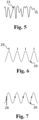
- a temporal value-string signal either periodic 22 or aperiodic 23, illustrated in Figs. 4 and 5 , is obtained by deriving an average or a median value from at least a portion of the images in real-time.
- the temporal value-string signal is derived from one of the 2D, cross-plane or 3D ultrasound image sequence by taking the mean value of all pixels (for 2D, cross-plane) or voxels (3D) in each image from the original image sequence, or by taking the median value of all pixels (2D, cross-plane) or voxels (3D) in each image from the original image sequence, or taking another single statistical parameter from all pixels (2D, cross-plane) or voxels (3D) in each image from the original image sequence.
- the temporal value-string signal is derived from the distance of the sensor to an anatomical structure in a predefined direction or in a predefined region.
- a value-string signal 26 is exemplarily shown, wherein the value-string signal is offset by the average of the distance for a time interval.
- the distance of the vessel wall to the sensor can be derived from an M-mode image, since the M-mode image is composed by information acquired along a single line in a certain time interval.
- the distance to the sensor can be derived as an average or a median value along the plurality of lines for the various angles to the vessel wall of the region of interest.
- the temporal 2D or 3D images are composed of a plurality of M-mode images, from which one or several can be selected to derive the temporal value-string signal.
- the temporal value-string signal may be a binary signal derived from the temporal M-mode image comprising periodic pattern due to contraction and relaxation of the cardiac tissue during periodic movement of the heart, e.g. according to the description from the 3 rd paragraph of column 12 to the antepenultimate paragraph of column 14, referring to Figs. 5A-5C and Fig. 6 , in US 8,774,906 .
- the temporal value-string signal may be derived from ultrasound M-mode image, as described in US 8,774,906 , or it may be derived from OCT M-mode image as presented in Fig. 3A on page 3802 of the article by Airong Li et al. in Human Molecular Genetics, 2013, Vol. 22, No. 18, pages 3798-3806 (doi:10.1093/hmg/ddt230 ).
- the temporal value-string signal may alternatively be derived directly from the raw or processed ultrasound or OCT signals, before the M-mode image is rendered.
- step 103 the processor ascertains whether the temporal information on the movement of the distal portion 30 of the interventional device 3 is periodic or aperiodic.
- the processor ascertains whether the temporal value-string signal 22,23 from step 102 is periodic or aperiodic.
- the running temporal value-string signal is windowed (in time) followed by the computation of the spectrum using the absolute values of the complex fast Fourier transformation (FFT) result.
- FFT complex fast Fourier transformation
- the period of the cycle is computed from the inverse value of the center frequency.
- the periodicity of the temporal information on the movement of the distal portion 30 of the interventional device 3 can be ascertained directly from the temporal measurement signal as received for the respective embodiments.
- the location information of the distal portion of the interventional device acquired by the extracorporeal imaging unit or by the sensor integrated into the distal portion of the interventional device with respect to the extracorporeal imaging unit may be directly used for ascertaining periodicity, whether the location information is related to 2D or 3D space.
- the distance of the anatomical structure to the sensor may be a 2D or 3D matrix derived from the respective 2D or 3D images and representing the coordinates of the anatomical structure or vectors defined by the magnitude and direction of the anatomical structure relative to the sensor in the respective 2D or 3D space.
- the processor triggers gating 24 of the temporal information of the periodically moving anatomy 41 in step 104.
- the method proceeds to the gating step 104.
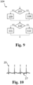
- the gating step 104 is schematically illustrated, comprising steps which may optionally be missing.
- the options branch out in two possibilities, depending on the predetermined configuration of the system, which can be adjusted by the physician or assisting personal via the user interface.
- step 107 When in step 107 the choice is detected that the gating should be based on the temporal information on the movement of the distal portion 30 of the interventional device 3 directly or based on the temporal value-string signal 22 derived from it in step 102, then in step 108 the gating will be performed based on that particular signal. On the other hand, if in step 107 the choice is detected that the gating should be based on a different signal than the temporal information on the movement of the distal portion 30 of the interventional device 3, then the signal for gating can be selected by the user in step 109.
- the gating signal may be one of a temporal extracorporeal electrocardiogram signal 27 ( Figs. 10 , 11 ) provided by the electrical signal measurement unit 8, e.g. electrocardiograph, or temporal intracorporeal electrogram signals provided by the at least one sensor integrated on the distal portion of the interventional device.
- the phase of the periodic signal used for gating may be predetermined in the configuration of the system and/or adjusted by the user through the user interface.
- the user interface will request from the user to introduce or confirm a selected phase.
- the processor uses automatic peak detection 29 ( Figs. 6 , 10 ) in step 112, or uses a certain predetermined phase that is delayed from the automatically detected peaks 29.
- the gated temporal information 25 of the periodically moving anatomy 41 can be a sequence of image frames corresponding to the same phase of consecutive periods used for gating, or other temporal measurement data of the periodically moving anatomy 41 corresponding to the same phase of consecutive periods used for gating.
- step 105 the processor outputs gated temporal information of the periodically moving anatomy 41 when the temporal information on the movement of the distal portion 30 of the interventional device 3 is ascertained periodic, and in step 106 outputs the temporal information of the periodically moving anatomy 41 as received when the temporal information on the movement of the distal portion 30 of the interventional device 3 is ascertained aperiodic.
- the processor outputs gated temporal information of the periodically moving anatomy or temporal information of the periodically moving anatomy as received at any instances during operation of the system.
- the gated temporal information of the periodically moving anatomy may be one of the M-mode, 2D, cross-plane, 3D visualization modalities of any of the ultrasound, X-ray, OCT, MR imaging modalities.
- the anatomy is a heart.
- the temporal measurement signals of the periodically moving heart are output as received, due to the fact that the physician or assisting personal needs real-time feedback to find the target location and it has to quickly react and correct the trajectory when the distal portion of the interventional device takes an undesired pathway.
- the distal portion of the interventional device is advanced or retracted with respect to the target location of interest.
- the interest of the physician or assisting personal is to obtain stable measurements or images.
- the temporal information of the periodically moving heart will be gated automatically, the apparatus outputting only the gated information when the catheter is not advanced or retracted relative to a the target location.
- the apparatus automatically switches to outputting the temporal information of the periodically moving heart as received, thereby automatically terminating outputting gated temporal information of the periodically moving heart.
- An exemplary visualization is illustrated on Fig. 12 , wherein the 3D ultrasound image of the heart chamber 41 is shown in the presence of the distal portion 30 of the interventional device.
- the images may further be post-processed by applying spatial and/or temporal filtering and adjusting the gray levels.
- the post-processing may require additional computation power, which may influence the real-time performance of the imaging.
- the at least one sensor e.g. sensor 31 in Fig. 2
- the at least one sensor is further configured to provide intracorporeal temporal information of the periodically moving anatomy 41 having higher resolution and smaller field of depth than the temporal information of the periodically moving anatomy 41 provided by the extracorporeal imaging unit 6.
- the anatomy is heart
- the intracorporeal temporal information of the heart is ultrasound information acquired by the ultrasound transducer 31 at a frequency in the interval of 20-45 MHz
- the extracorporeal temporal information of the heart is ultrasound information acquired by an extracorporeal ultrasound probe at a frequency in the interval of 1-10 MHz.
- the extracorporeal temporal information of a vessel of the heart is ultrasound information and the intracorporeal temporal information of the vessel of the heart is OCT information.
- the extracorporeal temporal information of the heart is X-ray information and the intracorporeal temporal information of the vessel of the heart is OCT or ultrasound information.
- the processor is further configured to register the extracorporeal and intracorporeal information of the periodically moving anatomy 41. The registration may be based on tracking of the sensor integrated on the distal portion of the interventional device by the extracorporeal imaging unit, by other tracking techniques listed in the description referring to the system illustrated in Fig.
- the registration of the extracorporeal and intracorporeal information of the periodically moving anatomy is performed before the gating step, and the temporal intracorporeal information of the periodically moving anatomy is gated similarly as the temporal extracorporeal information of the periodically moving anatomy.
- the processor is further configured to output to the display 20 the extracorporeal temporal information of the periodically moving anatomy 41 augmented by the intracorporeal information of the periodically moving anatomy 41.
- the processor is configured to render on the display intracorporeal images overlaid onto extracorporeal images at a position corresponding to the location of the sensor on the distal portion of the interventional device in the extracorporeal image.
- the processor is configured to compute the field of depth of the temporal intracorporeal information of the periodically moving anatomy and to render on the display extracorporeal images wherein the information according to the computed field of depth is substituted by the intracorporeal images. This alternative has particularly benefit where both the extracorporeal and intracorporeal images are ultrasound information acquired at different ultrasound frequencies.
- the temporal information of the periodically moving anatomy is related to morphological information of the anatomy
- the invention is applicable when the temporal information of the periodically moving anatomy comprises temporal physiological measurements such as blood pressure and blood flow measurements within the anatomy, that are measurable by one of the sensors 31 and 32, e.g. in vessel or in a chamber of the heart.
- the gated temporal physiological measurements can be output to the display additionally or alternatively to the gated temporal morphological information.
- a single unit or device may fulfill the functions of several items recited in the claims.
- the mere fact that certain measures are recited in mutually different dependent claims does not indicate that a combination of these measures cannot be used to advantage.
- a computer program may be provided, comprising program code means for causing apparatus 2 to carry out the steps of method 100 when the computer program is run on a computer controlling the apparatus.
- the computer program may be stored and/or distributed on a suitable medium, such as an optical storage medium or a solid-state medium, supplied together with or as part of other hardware, but may also be distributed in other forms, such as via the internet or other wired or wireless telecommunication systems.
Landscapes
- Health & Medical Sciences (AREA)
- Life Sciences & Earth Sciences (AREA)
- Engineering & Computer Science (AREA)
- Public Health (AREA)
- General Health & Medical Sciences (AREA)
- Medical Informatics (AREA)
- Molecular Biology (AREA)
- Veterinary Medicine (AREA)
- Pathology (AREA)
- Biomedical Technology (AREA)
- Heart & Thoracic Surgery (AREA)
- Physics & Mathematics (AREA)
- Biophysics (AREA)
- Surgery (AREA)
- Animal Behavior & Ethology (AREA)
- Nuclear Medicine, Radiotherapy & Molecular Imaging (AREA)
- Radiology & Medical Imaging (AREA)
- Physiology (AREA)
- Computer Vision & Pattern Recognition (AREA)
- Cardiology (AREA)
- Epidemiology (AREA)
- Primary Health Care (AREA)
- Artificial Intelligence (AREA)
- Psychiatry (AREA)
- Signal Processing (AREA)
- Ultra Sonic Daignosis Equipment (AREA)
- Magnetic Resonance Imaging Apparatus (AREA)
Claims (15)
- Appareil (2) pour visualiser des informations de mesure d'une anatomie à mouvement périodique (41), dans lequel l'appareil comprend un processeur (9) configuré pour:recevoir des signaux de mesure temporels (21) comprenant des informations temporelles sur le mouvement d'une partie distale (30) d'un dispositif d'intervention (3) et des informations temporelles de l'anatomie à mouvement périodique (41);déterminer si les informations temporelles sur le mouvement de la partie distale (30) du dispositif d'intervention (3) sont périodiques ou apériodiques;contrôler l'accès (24) des informations temporelles de l'anatomie à mouvement périodique (41) lorsque la périodicité est déterminée;délivrer les informations temporelles de l'anatomie à mouvement périodique (41) telles que reçues lorsque les informations temporelles sur le mouvement de la partie distale (30) du dispositif d'intervention (3) sont déterminées apériodiques, etdélivrer des informations temporelles à accès contrôlé (25) de l'anatomie à mouvement périodique (41) lorsque les informations temporelles sur le mouvement de la partie distale (30) du dispositif d'intervention (3) sont déterminées périodiques.
- Système (1) pour visualiser des informations d'une anatomie à mouvement périodique (41), comprenant:un appareil (2) selon la revendication 1;le dispositif d'intervention (3); etun afficheur (20) configuré pour afficher les informations délivrées par le processeur.
- Système selon la revendication 2, comprenant en outre une unité d'imagerie extracorporelle (6) configurée pour fournir les informations temporelles sur le mouvement de la partie distale (30) du dispositif d'intervention (3) et les informations temporelles de l'anatomie à mouvement périodique (41).
- Système selon la revendication 2, comprenant en outre une unité d'imagerie extracorporelle (6) configurée pour fournir les informations temporelles de l'anatomie à mouvement périodique (41), et dans lequel la partie distale (30) du dispositif d'intervention (3) comprend au moins un capteur (31, 32) configuré pour fournir les informations temporelles sur le mouvement de la partie distale (30) du dispositif d'intervention (3).
- Système selon la revendication 2, dans lequel la partie distale (30) du dispositif d'intervention (3) comprend au moins un capteur (31, 32) configuré pour fournir les informations temporelles sur le mouvement de la partie distale (30) du dispositif d'intervention (3) et les informations temporelles de l'anatomie à mouvement périodique (41).
- Système selon la revendication 4 ou 5, dans lequel les informations temporelles sur le mouvement de la partie distale (30) du dispositif d'intervention (3) et les informations temporelles de l'anatomie à mouvement périodique (41) sont des signaux ultrasonores, et dans lequel les informations temporelles sur le mouvement de la partie distale (30) du dispositif d'intervention (3) sont basées sur un mouvement de l'au moins un capteur par rapport à l'anatomie (41).
- Système selon la revendication 4 ou 5, dans lequel l'au moins un capteur est configuré pour fournir des signaux de tomographie par cohérence optique, et dans lequel les informations temporelles sur le mouvement de la partie distale (30) du dispositif d'intervention (3) sont basées sur un mouvement de l'au moins un capteur par rapport à l'anatomie (41).
- Système selon la revendication 6 ou 7, dans lequel le processeur est configuré pour restituer les informations temporelles de l'anatomie à mouvement périodique (41) en images de l'anatomie selon au moins l'un parmi un mode M, un mode 2D, un mode 3D et une modalité de visualisation multi-plans.
- Système selon la revendication 8, dans lequel la périodicité est déterminée sur la base d'un signal de chaîne de valeurs temporel (22, 23) obtenu en dérivant une valeur moyenne ou médiane à partir d'au moins une partie des images en temps réel.
- Système selon l'une quelconque des revendications 2 à 9, comprenant en outre une unité (8) configurée pour fournir au processeur des mesures de signaux d'électrocardiogramme extracorporels temporels (27) de l'anatomie à mouvement périodique, où le processeur est configuré pour contrôler l'accès (24) des informations temporelles de l'anatomie à mouvement périodique (41) selon une phase d'une période (T) des signaux d'électrocardiogramme extracorporels temporels mesurés.
- Système selon la revendication 4 ou 5, dans lequel l'au moins un capteur est configuré pour fournir au processeur des signaux de mesure de localisation spatiale temporels (26) sous forme d'informations temporelles sur le mouvement de la partie distale (30) du dispositif d'intervention (3), sur quoi le processeur est configuré pour déterminer la périodicité.
- Système selon la revendication 4 ou 5, dans lequel l'au moins un capteur est configuré pour fournir au processeur des signaux de mesure électrique temporels de l'anatomie à mouvement périodique résultant d'une activation électrique de l'anatomie, sur quoi le processeur est configuré pour contrôler l'accès des informations temporelles de l'anatomie à mouvement périodique (41).
- Système selon l'une quelconque des revendications 2 à 12, comprenant en outre une interface utilisateur configurée pour sélectionner une phase (28) de la période selon laquelle les informations temporelles de l'anatomie à mouvement périodique (41) sont à accès contrôlé.
- Système selon la revendication 4, dans lequel:
l'au moins un capteur est en outre configuré pour fournir des informations temporelles intracorporelles de l'anatomie à mouvement périodique (41) ayant une résolution plus élevée et un champ de profondeur plus petit que les informations temporelles de l'anatomie à mouvement périodique (41) fournies par l'unité d'imagerie extracorporelle, où le processeur est en outre configuré pour:enregistrer les informations extracorporelles et intracorporelles de l'anatomie à mouvement périodique (41),délivrer à l'afficheur les informations temporelles extracorporelles de l'anatomie à mouvement périodique (41) augmentées par les informations intracorporelles de l'anatomie à mouvement périodique (41) . - Programme informatique distribuable via internet ou d'autres systèmes de télécommunication avec ou sans fil ou stocké et/ou distribué sur un support lisible par ordinateur, le programme comprenant des moyens de code de programme qui, lorsqu'ils sont exécutés sur un processeur d'un appareil pour visualiser des informations de mesure d'une anatomie à mouvement périodique (41), amène le processeur à exécuter un procédé (100) de visualisation de signaux de mesure d'une anatomie à mouvement périodique (41), le procédé comprenant les étapes consistant à:- recevoir (101) des signaux de mesure temporels (26, 21) par un processeur (9), comprenant des informations temporelles sur le mouvement d'une partie distale (30) d'un dispositif d'intervention (3) et des informations temporelles de l'anatomie à mouvement périodique (41);- déterminer (103) par le processeur si les informations temporelles sur le mouvement de la partie distale (30) du dispositif d'intervention (3) sont périodiques ou apériodiques;- contrôler l'accès (104) des informations temporelles de l'anatomie à mouvement périodique (41) par le processeur lorsque la périodicité est déterminée;- délivrer (105) les informations temporelles de l'anatomie à mouvement périodique (41) telles que reçues lorsque les informations temporelles sur le mouvement de la partie distale (30) du dispositif d'intervention (3) sont déterminées apériodiques; et- délivrer des informations temporelles à accès contrôlé de l'anatomie à mouvement périodique (41) lorsque les informations temporelles sur le mouvement de la partie distale (30) du dispositif d'intervention (3) sont déterminées périodiques.
Applications Claiming Priority (2)
| Application Number | Priority Date | Filing Date | Title |
|---|---|---|---|
| EP18164256.2A EP3545849A1 (fr) | 2018-03-27 | 2018-03-27 | Appareil, système et procédé de visualisation d'une anatomie à mouvement périodique |
| PCT/EP2019/056643 WO2019185379A1 (fr) | 2018-03-27 | 2019-03-18 | Appareil, système et procédé de visualisation d'une anatomie à mouvement périodique |
Publications (2)
| Publication Number | Publication Date |
|---|---|
| EP3773229A1 EP3773229A1 (fr) | 2021-02-17 |
| EP3773229B1 true EP3773229B1 (fr) | 2024-05-08 |
Family
ID=61827608
Family Applications (2)
| Application Number | Title | Priority Date | Filing Date |
|---|---|---|---|
| EP18164256.2A Withdrawn EP3545849A1 (fr) | 2018-03-27 | 2018-03-27 | Appareil, système et procédé de visualisation d'une anatomie à mouvement périodique |
| EP19709975.7A Active EP3773229B1 (fr) | 2018-03-27 | 2019-03-18 | Appareil, système et procédé de visualisation d'une anatomie à mouvement périodique |
Family Applications Before (1)
| Application Number | Title | Priority Date | Filing Date |
|---|---|---|---|
| EP18164256.2A Withdrawn EP3545849A1 (fr) | 2018-03-27 | 2018-03-27 | Appareil, système et procédé de visualisation d'une anatomie à mouvement périodique |
Country Status (5)
| Country | Link |
|---|---|
| US (1) | US20210007715A1 (fr) |
| EP (2) | EP3545849A1 (fr) |
| JP (1) | JP6906113B2 (fr) |
| CN (1) | CN111918613A (fr) |
| WO (1) | WO2019185379A1 (fr) |
Families Citing this family (31)
| Publication number | Priority date | Publication date | Assignee | Title |
|---|---|---|---|---|
| WO2018187708A1 (fr) | 2017-04-07 | 2018-10-11 | Bard Access Systems, Inc. | Système de suivi et de surveillance de dispositif médical à base de fibre optique |
| WO2019045144A1 (fr) * | 2017-08-31 | 2019-03-07 | (주)레벨소프트 | Appareil et procédé de traitement d'image médicale pour dispositif de navigation médicale |
| WO2021030092A1 (fr) | 2019-08-12 | 2021-02-18 | Bard Access Systems, Inc. | Systèmes et procédés de détection de forme pour dispositifs médicaux |
| CN112826480B (zh) | 2019-11-25 | 2025-04-18 | 巴德阿克塞斯系统股份有限公司 | 具有滤波器的形状感测系统及其方法 |
| US11850338B2 (en) | 2019-11-25 | 2023-12-26 | Bard Access Systems, Inc. | Optical tip-tracking systems and methods thereof |
| CN113318324A (zh) | 2020-02-28 | 2021-08-31 | 巴德阿克塞斯系统股份有限公司 | 具有光学形状感测能力的导管 |
| CN215340440U (zh) | 2020-02-28 | 2021-12-28 | 巴德阿克塞斯系统股份有限公司 | 电学和光学连接系统及光学连接系统 |
| WO2021178578A1 (fr) | 2020-03-03 | 2021-09-10 | Bard Access Systems, Inc. | Système et procédé de détection de forme optique et de conduction de signal électrique |
| WO2021202589A1 (fr) | 2020-03-30 | 2021-10-07 | Bard Access Systems, Inc. | Systèmes de diagnostic optique et électrique et procédés associés |
| CN113842536B (zh) | 2020-06-26 | 2026-03-17 | 巴德阿克塞斯系统股份有限公司 | 错位检测系统 |
| WO2022005870A1 (fr) | 2020-06-29 | 2022-01-06 | Bard Access Systems, Inc. | Référence de cadre tridimensionnel automatique pour fibre optique |
| WO2022011287A1 (fr) | 2020-07-10 | 2022-01-13 | Bard Access Systems, Inc. | Surveillance de fonctionnalité continue de fibre optique et système de rapport d'auto-diagnostic |
| CN216675721U (zh) | 2020-08-03 | 2022-06-07 | 巴德阿克塞斯系统股份有限公司 | 布拉格光栅光纤波动感测与监测系统 |
| US12064569B2 (en) | 2020-09-25 | 2024-08-20 | Bard Access Systems, Inc. | Fiber optics oximetry system for detection and confirmation |
| CN216985791U (zh) | 2020-10-13 | 2022-07-19 | 巴德阿克塞斯系统股份有限公司 | 用于光纤连接器的消毒罩 |
| CN216455277U (zh) | 2020-10-13 | 2022-05-10 | 巴德阿克塞斯系统股份有限公司 | 用于将医疗器械插入患者体内的医疗器械系统 |
| CN216558785U (zh) | 2020-11-18 | 2022-05-17 | 巴德阿克塞斯系统股份有限公司 | 光纤管心针保持器 |
| US12220219B2 (en) | 2020-11-24 | 2025-02-11 | Bard Access Systems, Inc. | Steerable fiber optic shape sensing enabled elongated medical instrument |
| CN217040287U (zh) | 2021-01-06 | 2022-07-26 | 巴德阿克塞斯系统股份有限公司 | 用于将医疗器械插入患者体内的医疗器械系统 |
| CN114788733A (zh) | 2021-01-26 | 2022-07-26 | 巴德阿克塞斯系统股份有限公司 | 与端口放置相关联的光纤形状传感系统 |
| US12490937B2 (en) | 2021-05-18 | 2025-12-09 | Bard Access Systems, Inc. | Anatomical oscillation and fluctuation sensing and confirmation system |
| WO2023043947A1 (fr) | 2021-09-16 | 2023-03-23 | Bard Access Systems, Inc. | Interface de connexion de fibre à cycle d'accouplement élevé pouvant être remplacée |
| EP4418994A1 (fr) | 2021-10-25 | 2024-08-28 | Bard Access Systems, Inc. | Plan de référence pour la mise en place de dispositif médical |
| US12318149B2 (en) | 2022-03-08 | 2025-06-03 | Bard Access Systems, Inc. | Medical shape sensing devices and systems |
| US12426956B2 (en) | 2022-03-16 | 2025-09-30 | Bard Access Systems, Inc. | Medical system and method for monitoring medical device insertion and illumination patterns |
| US12089815B2 (en) | 2022-03-17 | 2024-09-17 | Bard Access Systems, Inc. | Fiber optic medical systems and devices with atraumatic tip |
| US12605116B2 (en) | 2022-04-11 | 2026-04-21 | Bard Access Systems, Inc. | Fiber optic medical systems and devices with electrical tip |
| US12575893B2 (en) | 2022-06-24 | 2026-03-17 | Bard Access Systems, Inc. | Shape sensing fiber optic tip protection systems and devices |
| US12343117B2 (en) | 2022-06-28 | 2025-07-01 | Bard Access Systems, Inc. | Fiber optic medical systems and methods for identifying blood vessels |
| US12349984B2 (en) | 2022-06-29 | 2025-07-08 | Bard Access Systems, Inc. | System, method, and apparatus for improved confirm of an anatomical position of a medical instrument |
| US12564340B2 (en) | 2022-07-12 | 2026-03-03 | Bard Access Systems, Inc. | Eccentric single-core fiber-optic enabled medical device |
Family Cites Families (22)
| Publication number | Priority date | Publication date | Assignee | Title |
|---|---|---|---|---|
| US8442618B2 (en) * | 1999-05-18 | 2013-05-14 | Mediguide Ltd. | Method and system for delivering a medical device to a selected position within a lumen |
| US9572519B2 (en) * | 1999-05-18 | 2017-02-21 | Mediguide Ltd. | Method and apparatus for invasive device tracking using organ timing signal generated from MPS sensors |
| US7204798B2 (en) * | 2003-01-24 | 2007-04-17 | Proteus Biomedical, Inc. | Methods and systems for measuring cardiac parameters |
| DE102004011156A1 (de) * | 2004-03-08 | 2005-10-06 | Siemens Ag | Verfahren zur endoluminalen Bildgebung mit Bewegungskorrektur |
| US7918793B2 (en) * | 2005-10-28 | 2011-04-05 | Biosense Webster, Inc. | Synchronization of ultrasound imaging data with electrical mapping |
| KR100961856B1 (ko) * | 2007-03-08 | 2010-06-09 | 주식회사 메디슨 | 초음파 영상을 형성하는 초음파 시스템 및 방법 |
| JP5639764B2 (ja) * | 2007-03-08 | 2014-12-10 | シンク−アールエックス,リミティド | 運動する器官と共に使用するイメージング及びツール |
| US8050523B2 (en) | 2007-04-20 | 2011-11-01 | Koninklijke Philips Electronics N.V. | Optical fiber shape sensing systems |
| US8319770B2 (en) * | 2008-07-11 | 2012-11-27 | General Electric Company | Method and apparatus for automatically adjusting user input left ventricle points |
| JP5662326B2 (ja) * | 2008-10-23 | 2015-01-28 | コーニンクレッカ フィリップス エヌ ヴェ | インターベンション・ラジオ波焼灼療法またはペースメーカー設置手順における、仮想的な解剖学的構造を豊かにしたリアルタイム2d撮像のための、心臓および/または呼吸同期画像取得システム |
| CN102421356B (zh) | 2009-05-15 | 2014-09-10 | 皇家飞利浦电子股份有限公司 | 用于确定心脏的性质的装置、方法以及计算机程序 |
| AU2011267954B2 (en) * | 2010-06-13 | 2014-07-24 | Angiometrix Corporation | Diagnostic kit and method for measuring balloon dimension in vivo |
| WO2013140358A1 (fr) * | 2012-03-23 | 2013-09-26 | Koninklijke Philips N.V. | Système d'imagerie pour l'imagerie d'un objet se déplaçant de façon périodique |
| EP2827779B1 (fr) | 2012-03-23 | 2017-07-05 | Koninklijke Philips N.V. | Système d'imagerie pour imager un objet se déplaçant périodiquement |
| EP2892433A1 (fr) * | 2012-09-05 | 2015-07-15 | Boston Scientific Scimed, Inc. | Caractérisation de tissu par échographie ultrasonore |
| US20140188440A1 (en) * | 2012-12-31 | 2014-07-03 | Intuitive Surgical Operations, Inc. | Systems And Methods For Interventional Procedure Planning |
| US10448860B2 (en) * | 2013-03-13 | 2019-10-22 | The Johns Hopkins University | System and method for bioelectric localization and navigation of interventional medical devices |
| US20150164605A1 (en) * | 2013-12-13 | 2015-06-18 | General Electric Company | Methods and systems for interventional imaging |
| US10912523B2 (en) * | 2014-03-24 | 2021-02-09 | Intuitive Surgical Operations, Inc. | Systems and methods for anatomic motion compensation |
| EP3181055A1 (fr) * | 2015-12-16 | 2017-06-21 | Universitätsklinikum Hamburg-Eppendorf | Dispositif ultrasonore destiné à détecter le rythme cardiaque d'un patient |
| US10022101B2 (en) * | 2016-02-29 | 2018-07-17 | General Electric Company | X-ray/intravascular imaging colocation method and system |
| WO2017201287A1 (fr) * | 2016-05-19 | 2017-11-23 | Acist Medical Systems, Inc. | Détection de position dans des processus intravasculaires |
-
2018
- 2018-03-27 EP EP18164256.2A patent/EP3545849A1/fr not_active Withdrawn
-
2019
- 2019-03-18 CN CN201980022579.2A patent/CN111918613A/zh active Pending
- 2019-03-18 JP JP2020551380A patent/JP6906113B2/ja not_active Expired - Fee Related
- 2019-03-18 WO PCT/EP2019/056643 patent/WO2019185379A1/fr not_active Ceased
- 2019-03-18 EP EP19709975.7A patent/EP3773229B1/fr active Active
- 2019-03-18 US US17/041,207 patent/US20210007715A1/en not_active Abandoned
Also Published As
| Publication number | Publication date |
|---|---|
| JP2021510601A (ja) | 2021-04-30 |
| CN111918613A (zh) | 2020-11-10 |
| JP6906113B2 (ja) | 2021-07-21 |
| US20210007715A1 (en) | 2021-01-14 |
| WO2019185379A1 (fr) | 2019-10-03 |
| EP3773229A1 (fr) | 2021-02-17 |
| EP3545849A1 (fr) | 2019-10-02 |
Similar Documents
| Publication | Publication Date | Title |
|---|---|---|
| EP3773229B1 (fr) | Appareil, système et procédé de visualisation d'une anatomie à mouvement périodique | |
| JP7047016B2 (ja) | 心内信号を利用した位置合わせマップ | |
| US20220167938A1 (en) | Apparatus for vessel characterization | |
| EP1699361B1 (fr) | Systeme de guidage d'un instrument medical dans le corps d'un patient | |
| US8126239B2 (en) | Registering 2D and 3D data using 3D ultrasound data | |
| EP3515288B1 (fr) | Visualisation d'un objet d'image concernant un instrument dans une image extracorporelle | |
| US12016652B2 (en) | System and method for real-time creation of cardiac electro-physiology signals in the heart | |
| US20030231789A1 (en) | Computer generated representation of the imaging pattern of an imaging device | |
| WO2014207605A1 (fr) | Système et procédé de mise en correspondance de mesures d'élastographie ultrasonore par ondes de cisaillement | |
| AU2014265090A1 (en) | Tracking of catheter from insertion point to heart using impedance measurements | |
| JP2001137206A (ja) | 心臓の腔の状態を心内膜的に検査するための方法と装置 | |
| MXPA06004653A (es) | Registro de mapa electroanatomico con imagen pre-adquirida usando ultrasonido. | |
| US20160345839A1 (en) | Temperature distribution determination apparatus | |
| US20200281562A1 (en) | Guiding an intravascular us catheter | |
| US20230263580A1 (en) | Method and system for tracking and visualizing medical devices | |
| US20230334679A1 (en) | A method of registering ultrasound images to an anatomical map | |
| US20250384551A1 (en) | Method and system for generating cardiac mechanical signals | |
| WO2014158380A1 (fr) | Système et méthode de localisation et de navigation bioélectrique | |
| EP3349659A1 (fr) | Appareil pour la caractérisation de vaisseau |
Legal Events
| Date | Code | Title | Description |
|---|---|---|---|
| STAA | Information on the status of an ep patent application or granted ep patent |
Free format text: STATUS: UNKNOWN |
|
| STAA | Information on the status of an ep patent application or granted ep patent |
Free format text: STATUS: THE INTERNATIONAL PUBLICATION HAS BEEN MADE |
|
| PUAI | Public reference made under article 153(3) epc to a published international application that has entered the european phase |
Free format text: ORIGINAL CODE: 0009012 |
|
| STAA | Information on the status of an ep patent application or granted ep patent |
Free format text: STATUS: REQUEST FOR EXAMINATION WAS MADE |
|
| 17P | Request for examination filed |
Effective date: 20201027 |
|
| AK | Designated contracting states |
Kind code of ref document: A1 Designated state(s): AL AT BE BG CH CY CZ DE DK EE ES FI FR GB GR HR HU IE IS IT LI LT LU LV MC MK MT NL NO PL PT RO RS SE SI SK SM TR |
|
| AX | Request for extension of the european patent |
Extension state: BA ME |
|
| STAA | Information on the status of an ep patent application or granted ep patent |
Free format text: STATUS: EXAMINATION IS IN PROGRESS |
|
| 17Q | First examination report despatched |
Effective date: 20210514 |
|
| DAV | Request for validation of the european patent (deleted) | ||
| DAX | Request for extension of the european patent (deleted) | ||
| GRAP | Despatch of communication of intention to grant a patent |
Free format text: ORIGINAL CODE: EPIDOSNIGR1 |
|
| STAA | Information on the status of an ep patent application or granted ep patent |
Free format text: STATUS: GRANT OF PATENT IS INTENDED |
|
| INTG | Intention to grant announced |
Effective date: 20231013 |
|
| GRAS | Grant fee paid |
Free format text: ORIGINAL CODE: EPIDOSNIGR3 |
|
| GRAA | (expected) grant |
Free format text: ORIGINAL CODE: 0009210 |
|
| STAA | Information on the status of an ep patent application or granted ep patent |
Free format text: STATUS: THE PATENT HAS BEEN GRANTED |
|
| AK | Designated contracting states |
Kind code of ref document: B1 Designated state(s): AL AT BE BG CH CY CZ DE DK EE ES FI FR GB GR HR HU IE IS IT LI LT LU LV MC MK MT NL NO PL PT RO RS SE SI SK SM TR |
|
| REG | Reference to a national code |
Ref country code: GB Ref legal event code: FG4D |
|
| REG | Reference to a national code |
Ref country code: CH Ref legal event code: EP |
|
| REG | Reference to a national code |
Ref country code: DE Ref legal event code: R096 Ref document number: 602019051889 Country of ref document: DE |
|
| REG | Reference to a national code |
Ref country code: IE Ref legal event code: FG4D |
|
| REG | Reference to a national code |
Ref country code: LT Ref legal event code: MG9D |
|
| REG | Reference to a national code |
Ref country code: NL Ref legal event code: MP Effective date: 20240508 |
|
| PG25 | Lapsed in a contracting state [announced via postgrant information from national office to epo] |
Ref country code: IS Free format text: LAPSE BECAUSE OF FAILURE TO SUBMIT A TRANSLATION OF THE DESCRIPTION OR TO PAY THE FEE WITHIN THE PRESCRIBED TIME-LIMIT Effective date: 20240908 |
|
| PG25 | Lapsed in a contracting state [announced via postgrant information from national office to epo] |
Ref country code: BG Free format text: LAPSE BECAUSE OF FAILURE TO SUBMIT A TRANSLATION OF THE DESCRIPTION OR TO PAY THE FEE WITHIN THE PRESCRIBED TIME-LIMIT Effective date: 20240508 |
|
| PG25 | Lapsed in a contracting state [announced via postgrant information from national office to epo] |
Ref country code: HR Free format text: LAPSE BECAUSE OF FAILURE TO SUBMIT A TRANSLATION OF THE DESCRIPTION OR TO PAY THE FEE WITHIN THE PRESCRIBED TIME-LIMIT Effective date: 20240508 Ref country code: FI Free format text: LAPSE BECAUSE OF FAILURE TO SUBMIT A TRANSLATION OF THE DESCRIPTION OR TO PAY THE FEE WITHIN THE PRESCRIBED TIME-LIMIT Effective date: 20240508 |
|
| PG25 | Lapsed in a contracting state [announced via postgrant information from national office to epo] |
Ref country code: GR Free format text: LAPSE BECAUSE OF FAILURE TO SUBMIT A TRANSLATION OF THE DESCRIPTION OR TO PAY THE FEE WITHIN THE PRESCRIBED TIME-LIMIT Effective date: 20240809 |
|
| PG25 | Lapsed in a contracting state [announced via postgrant information from national office to epo] |
Ref country code: PT Free format text: LAPSE BECAUSE OF FAILURE TO SUBMIT A TRANSLATION OF THE DESCRIPTION OR TO PAY THE FEE WITHIN THE PRESCRIBED TIME-LIMIT Effective date: 20240909 |
|
| REG | Reference to a national code |
Ref country code: AT Ref legal event code: MK05 Ref document number: 1684337 Country of ref document: AT Kind code of ref document: T Effective date: 20240508 |
|
| PG25 | Lapsed in a contracting state [announced via postgrant information from national office to epo] |
Ref country code: NL Free format text: LAPSE BECAUSE OF FAILURE TO SUBMIT A TRANSLATION OF THE DESCRIPTION OR TO PAY THE FEE WITHIN THE PRESCRIBED TIME-LIMIT Effective date: 20240508 |
|
| PG25 | Lapsed in a contracting state [announced via postgrant information from national office to epo] |
Ref country code: ES Free format text: LAPSE BECAUSE OF FAILURE TO SUBMIT A TRANSLATION OF THE DESCRIPTION OR TO PAY THE FEE WITHIN THE PRESCRIBED TIME-LIMIT Effective date: 20240508 |
|
| PG25 | Lapsed in a contracting state [announced via postgrant information from national office to epo] |
Ref country code: AT Free format text: LAPSE BECAUSE OF FAILURE TO SUBMIT A TRANSLATION OF THE DESCRIPTION OR TO PAY THE FEE WITHIN THE PRESCRIBED TIME-LIMIT Effective date: 20240508 |
|
| PG25 | Lapsed in a contracting state [announced via postgrant information from national office to epo] |
Ref country code: PL Free format text: LAPSE BECAUSE OF FAILURE TO SUBMIT A TRANSLATION OF THE DESCRIPTION OR TO PAY THE FEE WITHIN THE PRESCRIBED TIME-LIMIT Effective date: 20240508 |
|
| PG25 | Lapsed in a contracting state [announced via postgrant information from national office to epo] |
Ref country code: LV Free format text: LAPSE BECAUSE OF FAILURE TO SUBMIT A TRANSLATION OF THE DESCRIPTION OR TO PAY THE FEE WITHIN THE PRESCRIBED TIME-LIMIT Effective date: 20240508 |
|
| PG25 | Lapsed in a contracting state [announced via postgrant information from national office to epo] |
Ref country code: PT Free format text: LAPSE BECAUSE OF FAILURE TO SUBMIT A TRANSLATION OF THE DESCRIPTION OR TO PAY THE FEE WITHIN THE PRESCRIBED TIME-LIMIT Effective date: 20240909 Ref country code: PL Free format text: LAPSE BECAUSE OF FAILURE TO SUBMIT A TRANSLATION OF THE DESCRIPTION OR TO PAY THE FEE WITHIN THE PRESCRIBED TIME-LIMIT Effective date: 20240508 Ref country code: NO Free format text: LAPSE BECAUSE OF FAILURE TO SUBMIT A TRANSLATION OF THE DESCRIPTION OR TO PAY THE FEE WITHIN THE PRESCRIBED TIME-LIMIT Effective date: 20240808 Ref country code: NL Free format text: LAPSE BECAUSE OF FAILURE TO SUBMIT A TRANSLATION OF THE DESCRIPTION OR TO PAY THE FEE WITHIN THE PRESCRIBED TIME-LIMIT Effective date: 20240508 Ref country code: LV Free format text: LAPSE BECAUSE OF FAILURE TO SUBMIT A TRANSLATION OF THE DESCRIPTION OR TO PAY THE FEE WITHIN THE PRESCRIBED TIME-LIMIT Effective date: 20240508 Ref country code: IS Free format text: LAPSE BECAUSE OF FAILURE TO SUBMIT A TRANSLATION OF THE DESCRIPTION OR TO PAY THE FEE WITHIN THE PRESCRIBED TIME-LIMIT Effective date: 20240908 Ref country code: HR Free format text: LAPSE BECAUSE OF FAILURE TO SUBMIT A TRANSLATION OF THE DESCRIPTION OR TO PAY THE FEE WITHIN THE PRESCRIBED TIME-LIMIT Effective date: 20240508 Ref country code: GR Free format text: LAPSE BECAUSE OF FAILURE TO SUBMIT A TRANSLATION OF THE DESCRIPTION OR TO PAY THE FEE WITHIN THE PRESCRIBED TIME-LIMIT Effective date: 20240809 Ref country code: FI Free format text: LAPSE BECAUSE OF FAILURE TO SUBMIT A TRANSLATION OF THE DESCRIPTION OR TO PAY THE FEE WITHIN THE PRESCRIBED TIME-LIMIT Effective date: 20240508 Ref country code: ES Free format text: LAPSE BECAUSE OF FAILURE TO SUBMIT A TRANSLATION OF THE DESCRIPTION OR TO PAY THE FEE WITHIN THE PRESCRIBED TIME-LIMIT Effective date: 20240508 Ref country code: BG Free format text: LAPSE BECAUSE OF FAILURE TO SUBMIT A TRANSLATION OF THE DESCRIPTION OR TO PAY THE FEE WITHIN THE PRESCRIBED TIME-LIMIT Effective date: 20240508 Ref country code: AT Free format text: LAPSE BECAUSE OF FAILURE TO SUBMIT A TRANSLATION OF THE DESCRIPTION OR TO PAY THE FEE WITHIN THE PRESCRIBED TIME-LIMIT Effective date: 20240508 Ref country code: RS Free format text: LAPSE BECAUSE OF FAILURE TO SUBMIT A TRANSLATION OF THE DESCRIPTION OR TO PAY THE FEE WITHIN THE PRESCRIBED TIME-LIMIT Effective date: 20240808 |
|
| PG25 | Lapsed in a contracting state [announced via postgrant information from national office to epo] |
Ref country code: DK Free format text: LAPSE BECAUSE OF FAILURE TO SUBMIT A TRANSLATION OF THE DESCRIPTION OR TO PAY THE FEE WITHIN THE PRESCRIBED TIME-LIMIT Effective date: 20240508 |
|
| PG25 | Lapsed in a contracting state [announced via postgrant information from national office to epo] |
Ref country code: EE Free format text: LAPSE BECAUSE OF FAILURE TO SUBMIT A TRANSLATION OF THE DESCRIPTION OR TO PAY THE FEE WITHIN THE PRESCRIBED TIME-LIMIT Effective date: 20240508 |
|
| PG25 | Lapsed in a contracting state [announced via postgrant information from national office to epo] |
Ref country code: CZ Free format text: LAPSE BECAUSE OF FAILURE TO SUBMIT A TRANSLATION OF THE DESCRIPTION OR TO PAY THE FEE WITHIN THE PRESCRIBED TIME-LIMIT Effective date: 20240508 |
|
| PG25 | Lapsed in a contracting state [announced via postgrant information from national office to epo] |
Ref country code: SK Free format text: LAPSE BECAUSE OF FAILURE TO SUBMIT A TRANSLATION OF THE DESCRIPTION OR TO PAY THE FEE WITHIN THE PRESCRIBED TIME-LIMIT Effective date: 20240508 Ref country code: RO Free format text: LAPSE BECAUSE OF FAILURE TO SUBMIT A TRANSLATION OF THE DESCRIPTION OR TO PAY THE FEE WITHIN THE PRESCRIBED TIME-LIMIT Effective date: 20240508 |
|
| PG25 | Lapsed in a contracting state [announced via postgrant information from national office to epo] |
Ref country code: SM Free format text: LAPSE BECAUSE OF FAILURE TO SUBMIT A TRANSLATION OF THE DESCRIPTION OR TO PAY THE FEE WITHIN THE PRESCRIBED TIME-LIMIT Effective date: 20240508 |
|
| PG25 | Lapsed in a contracting state [announced via postgrant information from national office to epo] |
Ref country code: SM Free format text: LAPSE BECAUSE OF FAILURE TO SUBMIT A TRANSLATION OF THE DESCRIPTION OR TO PAY THE FEE WITHIN THE PRESCRIBED TIME-LIMIT Effective date: 20240508 Ref country code: SK Free format text: LAPSE BECAUSE OF FAILURE TO SUBMIT A TRANSLATION OF THE DESCRIPTION OR TO PAY THE FEE WITHIN THE PRESCRIBED TIME-LIMIT Effective date: 20240508 Ref country code: RO Free format text: LAPSE BECAUSE OF FAILURE TO SUBMIT A TRANSLATION OF THE DESCRIPTION OR TO PAY THE FEE WITHIN THE PRESCRIBED TIME-LIMIT Effective date: 20240508 Ref country code: EE Free format text: LAPSE BECAUSE OF FAILURE TO SUBMIT A TRANSLATION OF THE DESCRIPTION OR TO PAY THE FEE WITHIN THE PRESCRIBED TIME-LIMIT Effective date: 20240508 Ref country code: DK Free format text: LAPSE BECAUSE OF FAILURE TO SUBMIT A TRANSLATION OF THE DESCRIPTION OR TO PAY THE FEE WITHIN THE PRESCRIBED TIME-LIMIT Effective date: 20240508 Ref country code: CZ Free format text: LAPSE BECAUSE OF FAILURE TO SUBMIT A TRANSLATION OF THE DESCRIPTION OR TO PAY THE FEE WITHIN THE PRESCRIBED TIME-LIMIT Effective date: 20240508 |
|
| REG | Reference to a national code |
Ref country code: DE Ref legal event code: R097 Ref document number: 602019051889 Country of ref document: DE |
|
| PLBE | No opposition filed within time limit |
Free format text: ORIGINAL CODE: 0009261 |
|
| STAA | Information on the status of an ep patent application or granted ep patent |
Free format text: STATUS: NO OPPOSITION FILED WITHIN TIME LIMIT |
|
| 26N | No opposition filed |
Effective date: 20250211 |
|
| PG25 | Lapsed in a contracting state [announced via postgrant information from national office to epo] |
Ref country code: SI Free format text: LAPSE BECAUSE OF FAILURE TO SUBMIT A TRANSLATION OF THE DESCRIPTION OR TO PAY THE FEE WITHIN THE PRESCRIBED TIME-LIMIT Effective date: 20240508 |
|
| PG25 | Lapsed in a contracting state [announced via postgrant information from national office to epo] |
Ref country code: SE Free format text: LAPSE BECAUSE OF FAILURE TO SUBMIT A TRANSLATION OF THE DESCRIPTION OR TO PAY THE FEE WITHIN THE PRESCRIBED TIME-LIMIT Effective date: 20240508 |
|
| PG25 | Lapsed in a contracting state [announced via postgrant information from national office to epo] |
Ref country code: MC Free format text: LAPSE BECAUSE OF FAILURE TO SUBMIT A TRANSLATION OF THE DESCRIPTION OR TO PAY THE FEE WITHIN THE PRESCRIBED TIME-LIMIT Effective date: 20240508 |
|
| REG | Reference to a national code |
Ref country code: CH Ref legal event code: H13 Free format text: ST27 STATUS EVENT CODE: U-0-0-H10-H13 (AS PROVIDED BY THE NATIONAL OFFICE) Effective date: 20251023 |
|
| PG25 | Lapsed in a contracting state [announced via postgrant information from national office to epo] |
Ref country code: LU Free format text: LAPSE BECAUSE OF NON-PAYMENT OF DUE FEES Effective date: 20250318 |
|
| REG | Reference to a national code |
Ref country code: BE Ref legal event code: MM Effective date: 20250331 |
|
| PG25 | Lapsed in a contracting state [announced via postgrant information from national office to epo] |
Ref country code: FR Free format text: LAPSE BECAUSE OF NON-PAYMENT OF DUE FEES Effective date: 20250331 Ref country code: IT Free format text: LAPSE BECAUSE OF NON-PAYMENT OF DUE FEES Effective date: 20250318 |
|
| PG25 | Lapsed in a contracting state [announced via postgrant information from national office to epo] |
Ref country code: BE Free format text: LAPSE BECAUSE OF NON-PAYMENT OF DUE FEES Effective date: 20250331 |
|
| PG25 | Lapsed in a contracting state [announced via postgrant information from national office to epo] |
Ref country code: CH Free format text: LAPSE BECAUSE OF NON-PAYMENT OF DUE FEES Effective date: 20250331 |
|
| PG25 | Lapsed in a contracting state [announced via postgrant information from national office to epo] |
Ref country code: IE Free format text: LAPSE BECAUSE OF NON-PAYMENT OF DUE FEES Effective date: 20250318 |
|
| PGFP | Annual fee paid to national office [announced via postgrant information from national office to epo] |
Ref country code: GB Payment date: 20260319 Year of fee payment: 8 |
|
| PGFP | Annual fee paid to national office [announced via postgrant information from national office to epo] |
Ref country code: DE Payment date: 20260320 Year of fee payment: 8 |