EP3773253B1 - Kreuzkorde für bandligation - Google Patents
Kreuzkorde für bandligation Download PDFInfo
- Publication number
- EP3773253B1 EP3773253B1 EP19774335.4A EP19774335A EP3773253B1 EP 3773253 B1 EP3773253 B1 EP 3773253B1 EP 19774335 A EP19774335 A EP 19774335A EP 3773253 B1 EP3773253 B1 EP 3773253B1
- Authority
- EP
- European Patent Office
- Prior art keywords
- barrel
- cords
- band
- ligation
- bands
- Prior art date
- Legal status (The legal status is an assumption and is not a legal conclusion. Google has not performed a legal analysis and makes no representation as to the accuracy of the status listed.)
- Active
Links
Images





Classifications
-
- A—HUMAN NECESSITIES
- A61—MEDICAL OR VETERINARY SCIENCE; HYGIENE
- A61B—DIAGNOSIS; SURGERY; IDENTIFICATION
- A61B1/00—Instruments for performing medical examinations of the interior of cavities or tubes of the body by visual or photographical inspection, e.g. endoscopes; Illuminating arrangements therefor
- A61B1/00064—Constructional details of the endoscope body
- A61B1/00071—Insertion part of the endoscope body
- A61B1/0008—Insertion part of the endoscope body characterised by distal tip features
- A61B1/00087—Tools
-
- A—HUMAN NECESSITIES
- A61—MEDICAL OR VETERINARY SCIENCE; HYGIENE
- A61B—DIAGNOSIS; SURGERY; IDENTIFICATION
- A61B17/00—Surgical instruments, devices or methods
- A61B17/12—Surgical instruments, devices or methods for ligaturing or otherwise compressing tubular parts of the body, e.g. blood vessels or umbilical cord
- A61B17/12009—Implements for ligaturing other than by clamps or clips, e.g. using a loop with a slip knot
- A61B17/12013—Implements for ligaturing other than by clamps or clips, e.g. using a loop with a slip knot for use in minimally invasive surgery, e.g. endoscopic surgery
-
- A—HUMAN NECESSITIES
- A61—MEDICAL OR VETERINARY SCIENCE; HYGIENE
- A61B—DIAGNOSIS; SURGERY; IDENTIFICATION
- A61B1/00—Instruments for performing medical examinations of the interior of cavities or tubes of the body by visual or photographical inspection, e.g. endoscopes; Illuminating arrangements therefor
- A61B1/00064—Constructional details of the endoscope body
- A61B1/00071—Insertion part of the endoscope body
- A61B1/0008—Insertion part of the endoscope body characterised by distal tip features
- A61B1/00101—Insertion part of the endoscope body characterised by distal tip features the distal tip features being detachable
-
- A—HUMAN NECESSITIES
- A61—MEDICAL OR VETERINARY SCIENCE; HYGIENE
- A61B—DIAGNOSIS; SURGERY; IDENTIFICATION
- A61B17/00—Surgical instruments, devices or methods
- A61B17/12—Surgical instruments, devices or methods for ligaturing or otherwise compressing tubular parts of the body, e.g. blood vessels or umbilical cord
- A61B17/12009—Implements for ligaturing other than by clamps or clips, e.g. using a loop with a slip knot
-
- A—HUMAN NECESSITIES
- A61—MEDICAL OR VETERINARY SCIENCE; HYGIENE
- A61B—DIAGNOSIS; SURGERY; IDENTIFICATION
- A61B17/00—Surgical instruments, devices or methods
- A61B17/00234—Surgical instruments, devices or methods for minimally invasive surgery
- A61B2017/00238—Type of minimally invasive operation
- A61B2017/00269—Type of minimally invasive operation endoscopic mucosal resection EMR
-
- A—HUMAN NECESSITIES
- A61—MEDICAL OR VETERINARY SCIENCE; HYGIENE
- A61B—DIAGNOSIS; SURGERY; IDENTIFICATION
- A61B17/00—Surgical instruments, devices or methods
- A61B17/00234—Surgical instruments, devices or methods for minimally invasive surgery
- A61B2017/00292—Surgical instruments, devices or methods for minimally invasive surgery mounted on or guided by flexible, e.g. catheter-like, means
- A61B2017/00296—Surgical instruments, devices or methods for minimally invasive surgery mounted on or guided by flexible, e.g. catheter-like, means mounted on an endoscope
-
- A—HUMAN NECESSITIES
- A61—MEDICAL OR VETERINARY SCIENCE; HYGIENE
- A61B—DIAGNOSIS; SURGERY; IDENTIFICATION
- A61B17/00—Surgical instruments, devices or methods
- A61B17/12—Surgical instruments, devices or methods for ligaturing or otherwise compressing tubular parts of the body, e.g. blood vessels or umbilical cord
- A61B17/12009—Implements for ligaturing other than by clamps or clips, e.g. using a loop with a slip knot
- A61B2017/12018—Elastic band ligators
-
- A—HUMAN NECESSITIES
- A61—MEDICAL OR VETERINARY SCIENCE; HYGIENE
- A61B—DIAGNOSIS; SURGERY; IDENTIFICATION
- A61B17/00—Surgical instruments, devices or methods
- A61B17/30—Surgical pincettes, i.e. surgical tweezers without pivotal connections
- A61B2017/306—Surgical pincettes, i.e. surgical tweezers without pivotal connections holding by means of suction
-
- A—HUMAN NECESSITIES
- A61—MEDICAL OR VETERINARY SCIENCE; HYGIENE
- A61B—DIAGNOSIS; SURGERY; IDENTIFICATION
- A61B90/00—Instruments, implements or accessories specially adapted for surgery or diagnosis and not covered by any of the groups A61B1/00 - A61B50/00, e.g. for luxation treatment or for protecting wound edges
- A61B90/03—Automatic limiting or abutting means, e.g. for safety
- A61B2090/033—Abutting means, stops, e.g. abutting on tissue or skin
- A61B2090/036—Abutting means, stops, e.g. abutting on tissue or skin abutting on tissue or skin
Definitions
- Devices, methods, and systems are provided for band ligation, and especially for consistent and effective ligation band deployment.
- Endoscopic treatment of lesions is presently being accomplished through a variety of techniques.
- One technique involves ligation of lesions, in which mucosal and/or submucosal tissue is strangulated by an elastic band.
- Common current methods of performing this technique are variceal ligation and mucosal resection, which both use band ligation devices.
- Band ligation delivery systems generally consist of a ligation barrel, one or more pull cords, and one or more ligation bands.
- the one or more pull cords extend distally through a lumen in the ligation barrel, loop around a distal end of the ligation barrel, and then extend proximally along an exterior surface of the ligation barrel.
- the cords each have one or more knots or beads formed thereon at specific locations that are each designed to engage with a corresponding ligation band.
- Each ligation band is loaded on to the ligation barrel by positioning the band around the ligation barrel and the pull cords. As such, each ligation band holds the cords on the exterior surface of the barrel and is positioned distally to its corresponding beads.
- the beads are pulled distally along the exterior surface of the ligation barrel toward the distal end of the barrel, and each band in turn is pushed distally by the corresponding beads.
- the beads loop around the distal end to be pulled proximally through the lumen of the barrel and each corresponding ligation band is sequentially deployed from the distal end of the barrel to capture tissue held by the ligation barrel.
- a device according to the preamble of claim 1 is known from EP2136719 B1 .
- devices, methods, and systems are provided for consistent and effective ligation band deployment from band ligation devices.
- a band ligation apparatus in one embodiment, includes an elongate barrel having a proximal end matable to an endoscope, a distal end, and an inner lumen extending through the proximal and distal ends.
- a plurality of bands are disposed circumferentially around an external surface of the elongate barrel.
- First and second cords are included, and each cord extends from a terminal trailing end, distally along the external surface of the elongate barrel, around the distal end, and proximally through the inner lumen such that a leading end of each cord extends proximally from the elongate barrel.
- the first and second cords overlap one another to form a crisscross pattern along the external surface, and the first and second cords have a plurality of beads immovably disposed thereon and positioned between each of the plurality of bands for deploying the bands.
- proximal retraction of the leading end of each of the first and second cords can be configured to cause the plurality of beads to sequentially advance the plurality of bands distally to deploy the bands around tissue drawn into the inner lumen of the elongate barrel.
- the elongate barrel can have a horizontal plane extending along a longitudinal axis of the inner lumen and through the distal end defining first and second sides of the elongate barrel, and the crisscross pattern can be formed only on one of the first and second sides of the elongate barrel.
- the crisscross pattern of the first and second cords can include the first and second cords being looped around each other at each point of overlap along the external surface.
- Each point of overlap by the first and second cords along the external surface can be arranged in a line on the external surface that extends parallel to a longitudinal axis of the inner lumen.
- the distal end of the elongate barrel can have a terminal end surface extending at an oblique angle to a longitudinal axis of the inner lumen such that the terminal end surface has a distal-most point, a proximal-most point, and first and second opposed mid-points positioned equidistant between the distal-most and proximal-most points.
- the elongate barrel can have a horizontal plane extending along the longitudinal axis of the inner lumen and through the first and second opposed mid-points to define a first horizontal segment of the elongate barrel including the distal-most point, and a second horizontal segment of the elongate barrel including the proximal-most point.
- each cord can be positioned on the first horizontal segment of the elongate barrel.
- Each cord can extend distally from the terminal trailing end along only the first horizontal segment on the external surface of the elongate barrel.
- the elongate barrel can include at least one notch formed thereon adjacent the distal end, and the at least one notch can be configured to seat and/or delay a band during deployment of the bands.
- the external surface of the elongate barrel can have at least one lip formed adjacent the distal end of the elongate barrel and configured to engage and delay deployment of each of the plurality of bands.
- the elongate barrel can have at least one tissue-stopping protrusion projecting radially inward from an inner sidewall of the inner lumen.
- a band ligation apparatus in another embodiment, includes a hollow elongate barrel with a proximal end and a distal end with a terminal surface.
- First and second cords can extend through the hollow elongate barrel, around the terminal surface, and along an outer surface of the hollow elongate barrel, and the first and second cords can have a plurality of beads immovably disposed thereon.
- a plurality of bands can be disposed circumferentially around the hollow elongate barrel and the first and second cords, and the plurality of bands can be spaced axially therealong. At least one of the plurality of beads on each of the first and second cords can be positioned between each of the plurality of bands for deploying the bands.
- the first and second cords can engage one another between each of the plurality of bands along the outer surface.
- the apparatus can have numerous variations.
- the first and second cords can be twisted together as they engage.
- the first and second cords can engage one another along the outer surface of the hollow elongate barrel in an approximately straight line parallel to a longitudinal axis of the hollow elongate barrel.
- the terminal surface of the hollow elongate barrel can have one of an oblique angle and a perpendicular angle relative to a longitudinal axis of the hollow elongate barrel.
- the hollow elongate barrel can have at least one ledge projecting radially inward from an inner sidewall of the hollow elongate barrel.
- proximal retraction of the leading end of each of the first and second cords can be configured to cause the plurality of beads to sequentially advance the plurality of bands distally to deploy the bands around tissue drawn into the inner lumen of the elongate barrel.
- a method for loading a plurality of bands onto a ligation barrel includes positioning a first bead on a terminal end of a first cord at a first location on an outer surface of a ligation barrel, and positioning a second bead on a second cord at a second location on the outer surface of the ligation barrel.
- the first and second locations are spaced equidistant from a distal end of the ligation barrel relative to each other and are spaced circumferentially from each other on the ligation barrel.
- the method also includes advancing a first band onto the ligation barrel to position the first band distally adjacent the first and second beads.
- the method After advancing the first band onto the ligation barrel, the method includes crossing the first and second cords at least once. The method further includes positioning a third bead on the first cord longitudinally distal to one of the first and second beads and positioning a fourth bead on the second cord longitudinally distal to the other of the first and second beads. The method also includes advancing a second band onto the endoscopic barrel to position the second band distally adjacent to the third and fourth beads.
- the method can have various embodiments.
- the method can include, after advancing the second band onto the ligation barrel, crossing the first and second cords at least once and then positioning a fifth bead on the first cord longitudinally distal to one of the third or fourth beads and positioning a sixth bead on the second cord longitudinally distal to the other of the third or fourth beads.
- the method can also include advancing a third band onto the endoscopic barrel to position the third band distally adjacent the fifth and sixth beads.
- crossing the first and second cords at least once includes twisting the first and second cords together at least once.
- Devices, methods, and systems are provided herein for band ligation, including an approach to band deployment that provides consistent, effective band delivery. Consistent and even delivery of each ligation band to tissue is important to ensure tissue is cleanly grasped and ligated. Effective delivery can be achieved by ensuring that each ligation band is freed from the ligation barrel all at once, which can be difficult to accomplish when using two or more pull cords that extend parallel to each other along the exterior surface of the ligation barrel. A crisscrossed or engaged orientation between the pull cords along the exterior surface of the ligation barrel is thus provided to ensure consistent delivery of ligation bands to tissue and better visibility through the ligation barrel during use, resulting in better results for patients and an easier, safer operation for users.
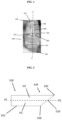
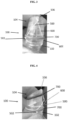
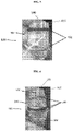
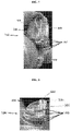
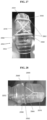
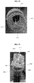
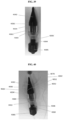
- FIGS. 1-12 illustrate one embodiment of a band ligation apparatus 100 for use with pull cords 500, 600 having a crisscrossed or engaged orientation.
- the band ligation apparatus 100 has a hollow elongate cylindrical barrel 102 with a proximal end 103 matable to an endoscope and/or configured to receive an imaging device therein, a distal end 104, and an inner lumen extending through the proximal and distal ends 103, 104.
- the proximal end 103 can be elastic for fitting over a distal end of an endoscope.
- the proximal end 103 can also include features to facilitate engagement of an endoscope, such as three elastic grooves or rings formed on an interior of the barrel 102 at the proximal end 103 that can stretch to mate with distal ends of imaging devices having cross-sectional areas of different sizes, as explained in more detail below.
- an endoscope such as three elastic grooves or rings formed on an interior of the barrel 102 at the proximal end 103 that can stretch to mate with distal ends of imaging devices having cross-sectional areas of different sizes, as explained in more detail below.
- any mating feature can be used, such as ridges, threading, straps, etc.
- the distal end 104 can have a terminal end surface that extends at an oblique angle to a longitudinal axis L1 of the inner lumen.
- the terminal end surface of the angled distal end 104 has a distal-most point 106 and a proximal-most point 108, for example as shown in FIG. 2 .
- a horizontal plane P1 can extend along the axis L1 and through a mid-point 110 positioned equidistant between the distal-most point 106 and the proximal-most point 108, figuratively dividing the cylindrical barrel 102 into a first or high horizontal segment H1 and a second or low horizontal segment H2, as illustrated in FIG. 2 .
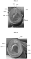
- the angled distal end 104 results in an opening with an ellipse or oval shape, for example as illustrated in FIGS. 8 and 10 .
- the ellipse shape results in the distal end 104 having two diameters, a first being formed by a left-to-right or primary diameter that extends perpendicular to the longitudinal axis L1 and a second being formed by the distance from the distal-most point 106 to the proximal-most point 108. This second diameter can be extended in length by changing the angle of the terminal end surface of the distal end 104 relative to the axis L1.
- the angle can have a variety of ranges, for example from about 0 degrees to about 90 degrees, about 10 degrees to about 40 degrees, and more specifically about 20 degrees to about 30 degrees, such as around 29 degrees.
- the area of tissue captured can be increased by changing the angle while leaving the primary diameter unchanged. For example, it is possible to increase the area of tissue capture by up to 50%. Extra length of the secondary diameter does not negatively affect maneuverability, such as when using intubation and/or when inserting into a lumen of a GI tract of a patient, while allowing greater tissue capture because the distal end 104 is angled forward and does not increase the primary diameter to maintain a smaller cross-sectional profile in the intubation tube.
- the increased secondary diameter can be easier to intubate than a straight circular distal end when mated with the endoscope because of the projecting distal-most point 106, and it can be easier to make contact and begin creating a vacuum to suction tissue into the barrel.
- a distal end of a band ligation apparatus can be approximately straight rather than angled, having a terminal end surface that extends at an approximately right or perpendicular angle to the longitudinal axis L1.
- Two or more pull cords 500, 600 can each be configured to extend from a terminal trailing or distal end distally along the external surface eof the barrel 102, loop around the distal end 104, and extend proximally through the inner lumen of the barrel. Terminal leading or proximal ends of each of the cords 500, 600, which extend proximally from the inner lumen of the barrel, can engage with a handle or other pull mechanism positioned proximal to the apparatus 100. As such, the cords 500, 600 can be pulled proximally through the inner lumen of the barrel 102, which can result in pulling terminal distal ends of the cords 500, 600 (located against the external surface of the barrel 102) distally along the external surface of the apparatus 100.
- Each of the cords 500, 600 are subsequently pulled around the distal end 104 and pulled entirely within the inner lumen of the barrel 102 to continue to move proximally through the barrel 102.
- Beads or knots 502, 602 can be spaced axially and immovably fixed along at least a distal portion of each cord 500, 600, and the beads 502, 602 can be configured to engage with ligation bands 700.
- One or more ligation bands 700 can be configured to wrap around the outer surface of the apparatus 100 on a distal portion thereof.
- the bands 700 can be pushed distally by retraction of the cords 500, 600 and corresponding distal movement of the beads 502, 602 such that each band 700 is deployed sequentially off the distal end 104 of the apparatus 100 when each corresponding bead 502, 602 loops over the distal end 104 and is pulled into the barrel 102.
- Spacing of the beads 502, 602 and lengths of the cords 500, 600 can be varied such that proximal movement of proximal terminal ends of the cords 500, 600 will result in deployment of ligation bands 700 at known distances.
- spacing between an initial bead 502, 602 at the distal terminal end of each of the cords 500, 600 and a second subsequent bead 502, 602 can be longer than the spacing between the second subsequent bead 502, 602 and a third subsequent bead 502, 602. Therefore, the initial bead 502, 602 can be loaded first on the apparatus 100 with a corresponding band 700 and will thus be last to cause deployment of the band 700.
- the spacing length can consequently be longer to accommodate the longer distance required to move the last band 700 distally to deploy.
- the spacing of the beads can also be equidistant in some embodiments.
- the cords 500, 600 can be engaged with or crisscross each other between each band 700 to allow an even, consistent deployment of the bands 700.
- Each band 700 can be deployed from the angled distal end 104 all at once, avoiding one side of the band 700 (on the side of the low horizontal segment H2) from being deployed before a second side of the band 700 (on the side of the high horizontal segment H1). If parts of the band 700 come free from the distal end 104 before others, delivery of the band 700 can be uneven.
- the pull cords 500, 600 are prevented from slipping or sliding to the low horizontal segment H2, which would cause uneven advancement of the bands and an uneven delivery.
- beads 502, 602 on the distal terminal ends of the cords 500, 600 can be aligned on the outer surface of the apparatus 100 proximal to where the first band 700 to be loaded (and thus the last band 700 to be deployed) will be placed.
- the first beads 502, 602 can be positioned on the same side as the high horizontal segment H1 of the cylindrical barrel 102 to help ensure that the band 700 will be deployed correctly.
- the first beads 502, 602 can be positioned between 9 o'clock and 3 o'clock, for example at 10 o'clock and 2 o'clock or 11 o'clock and 1 o'clock, or somewhere therebetween.
- a first band 700 can be advanced over the cords 500, 600 to position the first band 700 on the barrel 102 at a location immediately distal of the beads 502, 602.
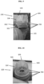
- the cords 500, 600 can be engaged with each other, for example by being crisscrossed as illustrated in FIG. 3 .
- the beads 502, 602 will remain on the high horizontal segment H1 as they are pulled behind their corresponding band 700, and the beads 502, 602 will move toward the distal-most point 106 (corresponding to 12 o'clock along the high horizontal segment H1 of the barrel 102).
- the cords 500, 600 can be crossed once or can be looped or twisted around each other one or more times.
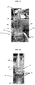
- the second set of beads 502, 602 and the second band 700 can then be loaded over the cords 500, 600 to position the second band 700 immediately distal of the second set of beads 502, 602, as illustrated in FIGS. 4-6 .
- the second band 700 to be loaded will be the second-to-last band 700 to be fired, and the band 700 can optionally be a different color from the remaining bands to indicate its position to a user during deployment.
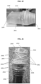
- the process can be repeated to load the remaining bands, as illustrated in FIGS. 7-11 .
- each set of beads 502, 602 can move radially outward away from the 12 o'clock position along the outer surface of the apparatus 100 as each band 700 is pushed toward the previously-loaded band 700 until the beads 502, 602 are tight and lined up with any previously-loaded beads 502, 602.
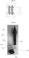
- FIG. 12 illustrates a simplified diagram with sets of beads 502, 602 and corresponding bands 700 labeled to indicate a possible order of loading and to illustrate the crisscrossing of the cords 500, 600 between each set of beads 502, 602 and corresponding band 700. While the cords 500, 600 are crossed once in FIG. 12 , the cords can be twisted one or more times.
- the beads 502, 602 will align with beads 502, 602 from the same cord 500, 600. If the cords are crossed and twisted an even number of times, the beads 506, 602 will align with beads 502, 602 from the other cord 500, 600. While crisscrossing or engaging the cords 500, 600 is discussed with reference to the angled distal end 104, a similar approach can be used on a straight distal end, as discussed below.
- each point of crisscrossing or engagement between the cords 500, 600 can be positioned on a same side of the exterior surface of the barrel every time, as illustrated above with reference to the apparatus 100 having an angled distal end 104, or can be positioned on an opposite side for some of the points of crisscrossing or engagement.
- a plurality of bands and beads can be loaded until a user is satisfied, for example 10 ligation bands or more.
- the proximal terminal ends of the cords 500, 600 can be looped around the distal end 104 of the band ligation apparatus 100 and can be extended proximally through the barrel 102 and optionally through an endoscope.
- the cords 500, 600 can optionally be knotted together within the barrel 102 or proximal to the barrel 102 to ensure that the cords 500, 600 are pulled evenly together during later deployment.
- the cords 500, 600 can also optionally be engaged with various handles and/or pulling mechanisms (for example on a proximal end of an endoscope) for use during later deployment.
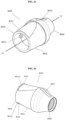
- an optional notch 112 can be formed close to the proximal-most point 108 of the terminal end surface along the distal end 104 on the low horizontal segment H2, as illustrated in FIG. 13 .
- the notch 112 can engage each ligation band 700 during deployment to help ensure even deployment (as explained below).
- the notch 112 as illustrated is formed by a distally-inward sloped outer surface on the low horizontal segment H2 that terminates proximal of the terminal distal end, thereby defining a rim 112a distally adjacent the notch 112.
- the sloped surface can have between approximately 1 and 20 degrees of slope, and more specifically between approximately 5 and 10 degrees, such as 8 degrees of slope.
- the notch can be in the form of a groove, channel, bump, hook, engagement feature, etc. While a notch is illustrated herein, ligation barrels using a crisscrossing or engaging pull cord orientation are possible that do not include notches.
- a loading apparatus 200 can also optionally be used to assist a user in loading one or more ligation bands 700 onto the band ligation apparatus 100, as illustrated in FIGS. 14-20 .
- the illustrated loading apparatus 200 includes a rigid cone with a distal-most point 202 that increases in diameter radially in a proximal direction until it reaches an engagement edge or groove 204 that fits flush with the distal end 104 of the band ligation apparatus 100.
- the engagement edge 204 has a diameter and shape corresponding to the diameter and shape of the distal end 104 of the apparatus 100 such that the loading apparatus 200 can be securely fit into the oval shape of the distal end 104.
- the loading apparatus 200 is oblique to ensure the loading apparatus 200 can only engage the band ligation apparatus 100 in one, correct orientation.
- the cone-shape of the loading apparatus 200 can dilate ligation bands 700 such that the bands 700 are able to stretch and slide onto the barrel 102 for eventual deployment.
- a shaft 204 extending proximally from the engagement edge 204 fits along the hollow elongate cylindrical barrel 102 and extends proximally therefrom, as illustrated in FIG. 15 .
- at least a proximal section of the shaft 204 can be threaded to receive a nut 205 therearound.
- an outer surface of the loading apparatus 200 can have marks on it to indicate proper alignment of cords 500, 600 and bands 700 during loading.
- the marks can indicate preferred loading alignments on the high horizontal segment H1 of the cylindrical barrel 102.
- the band ligation apparatus 100 can mate or engage with a variety of different imaging devices and/or endoscopes.
- An exemplary endoscope can have illumination and viewing apparatus(es) to facilitate orientation within the body of a patient, longitudinally extending tubular passages such as one or more channels through which objects may be passed and suction applied for drawing tissue into the distal end 104 of the apparatus 100 to facilitate ligation of a lesion, and a working channel through which one or more flexible actuating cables can be inserted.
- suction can be applied to the endoscope to draw tissue to be ligated into the distal end 104 of the hollow barrel 102 of the band ligation apparatus 100.
- a user can retract the cords 500, 600 proximally, which will cause the set of beads 502, 602 positioned distal-most on the outer surface of the apparatus 100 to begin to move distally along the outer surface.
- the crisscrossed pattern of the cords 500, 600 will cause each bead 502, 602 to move toward the distal-most point 106 (corresponding to 12 o'clock along the high horizontal segment H1 of the cylindrical barrel 102) as the beads 502, 602 are moved distally and push their corresponding band 700 distally.
- the beads 502, 602 will be crisscrossed and equidistant from a center of the high horizontal segment H1. Thus each set of beads 502, 602 will deploy their corresponding band 700 evenly despite the angled distal end 104 because they will be drawn toward the distal-most point 106. Because the cords 500, 600 are both loaded on a same side of the barrel 102 (the high horizontal segment H1), they can be retracted proximally through the barrel 102 on a same side and thus can allow for increased visibility through the barrel 102.
- the notch 112 engages each band 700 as it is drawn distally for deployment.
- the notch 112 acts to delay firing of each band 700 on the side of the low horizontal segment H2 until the band 700 has reached the distal end 104 on the side of the high horizontal segment H1.
- the band 700 is released either simultaneously all around or is released on the side of the high horizontal segment H1 first.
- the delayed release on the side of the low horizontal segment H2 can help prevent the band 700 from deploying unevenly and potentially firing straight across the distal end 104 of the apparatus 100 instead of capturing tissue therein.
- FIG. 21 illustrates a band ligation apparatus 1000 that generally corresponds to apparatus 100 and has pull cords 1002, 1004, ligation bands 1006, and a hollow elongate cylindrical barrel 1008.
- the barrel 1008 has a cord alignment feature, represented here by a tube 1020, extending along an inner surface of the barrel 1008 and running parallel to a longitudinal axis of the barrel 1008.
- the tube 1020 is positioned at least along a distal portion of the barrel 1008 such that its distal terminal end is positioned close to a distal end 1010 of the barrel 1008.
- the tube 1020 is also approximately aligned with a distal-most point of the distal end 1010 of the barrel 1008, corresponding generally to 12 o'clock (as discussed above in apparatus 100).
- the tube 1020 can be configured to receive the cords 1002, 1004 therethrough. As such, when the cords 1002, 1004 are pulled proximally to deploy the ligation bands 1006, the cords 1002, 1004 are maintained in proper alignment to ensure even deployment, for example by maintaining the cords 1002, 1004 within a range of between approximately 9 o'clock and 3 o'clock.
- FIG. 22 illustrates a band ligation apparatus 1050 with a barrel 1052, bands 1054, and cords 1056, 1058 similar to apparatus 100. However, it has a ring 1060 positioned at approximately the same point as the tube 1020 and configured to align the cords 1056, 1058 during actuation.
- the alignment features can allow the cords to come close together at the distal-most point of the band ligation apparatus to help ensure one central pulling force on the cords. If a loading apparatus is used, the corresponding loading apparatus can also have a corresponding channel or groove thereon to receive the alignment feature so that the loading device has an outer surface that is shaped to complement the shape of the inner lumen of the barrel to achieve a flush fit.
- FIGS. 23 and 24 illustrate another embodiment of a band ligation apparatus 2000 that is similar to apparatus 100 and has a hollow elongate cylindrical barrel 2002 with distal and proximal ends 2004, 2006.
- the distal end 2004 is angled similar to apparatus 100, and it has a distal-most point 2010 and a proximal-most point 2012 located on the terminal end surface.
- a hoop 2014 is generally aligned with the distal-most point 2010 and acts to align pull cords during use.
- the hollow barrel 2002 has a tissue-stopping feature, represented here by a ledge 2020, that is positioned within and formed on an inner surface of the barrel 2002.
- the ledge 2020 can extend at least partially around the circumference of the inner surface of the barrel 2002, and as can be seen in FIGS. 23 and 24 , can include two or more separate ledges protruding inwardly from opposite sides of the inner surface.
- the ledge 2020 can be configured to allow the cords to extend therethrough while stopping tissue from being retracted too far into the barrel 2002.
- the ledge 2020 can have an angle that is the same as the angle of the distal end 2004 of the apparatus 2000.
- the angle of the ledge 2020 and the distal end 2004 can be 29 degrees (with the distal-most point 2010 located at 29 degrees and the proximal-most point 2012 located at 0 degrees).
- the angle can be varied as explained above from approximately 0 degrees to approximately 90 degrees.
- the depth of the ledge 2020 can be approximately 7 mm to prevent tissue from being drawn into the barrel 2002 any deeper than 7 mm. Because the ledge 2020 is angled similarly to the distal end 2004, the depth of the ledge 2020 represents the distance from the distal end 2004 all around. 7 mm is approximately the depth used to draw in tissue without drawing in any muscle. However, a variety of different depths can be used depending on the desired use. Without the ledge 2020, tissue can potentially be drawn into the barrel 2002 until it hits the corresponding scope, and when tissue is ligated, the tissue on the high side will be deeper. This can potentially leave an uneven ligation in the shape of a wedge.
- the ledge 2020 is thus configured to allow suction and maintain visualization for the user while also ensuring that acceptable amounts of tissue are ligated. While ledges are illustrated, a variety of different protuberances can be used, such as tabs, bumps, cylinders, etc. While a depth of approximately 7 mm is provided, any depth can be used. For example, a depth can range from approximately 4 mm to approximately 12 mm, or approximately 4 mm, 5 mm, 6 mm, 7 mm, 8 mm, 9 mm, 10 mm, 11 mm, 12 mm, etc.
- FIG. 25 illustrates another embodiment of a band ligation apparatus 2030 that is similar to the apparatus 100 and has a hollow elongate cylindrical barrel 2032 with distal and proximal ends 2034, 2036.
- the distal end 2034 is angled similar to apparatus 100.
- the apparatus 2030 has a bump 2038 that functions similar to notch 112.
- the bump 2038 can be formed close to a proximal-most point of the distal end 2034 and can be configured to engage and delay each ligation band during deployment (as explained above).
- FIGS. 26-32 illustrate another embodiment of a band ligation apparatus 2050 that is similar to apparatus 100 and that has a hollow elongate cylindrical barrel 2052 with distal and proximal ends 2054, 2056.
- the apparatus 2050 is configured to be disposed on a distal end of an endoscope 2058, and the distal end 2054 is angled similar to apparatus 100 such that, for reference purposes, it has a distal-most point 2060 and a proximal-most point 2062.
- Bands 2062 and cords 2064, 2066 with beads 2068 are disposed thereon.
- the beads 2068 are disposed on at least one of the cords 2064, 2066 at regular intervals (i.e., equidistant from one another) along at least distal portions thereof. Because the bands 2062 may need to travel different distances along the outer surface of the barrel 2052 to be deployed based on their loading order, the cords 2064, 2066 can be twisted one or more times to form twisted points 2070 between subsequent bands 2062 to prevent excess cord from accidentally causing a jam or double deployment. The one or more twists in the cords 2064, 2066 are thus configured to reduce slack in the cords 2064, 2066.
- the number of twists per twisted point 2070 can vary depending on the length of the cords and the position of the beads. For example, four twists can be used for a first twisted point 2070, three for a second, etc., to make cords into the desired lengths so that tension is applied to the bands at proper times.
- the twisted points 2070 can also assist in keeping beads 2068 between a 9 o'clock and a 3 o'clock range (assuming 12 o'clock corresponds to the distal-most point 2060). Because one or more twists can be used in the cords, beads can have a variety of arrangements in other embodiments. For example, all beads 2068 for one cord 2062 can align with each other while all beads 2068 for the other cord 2064 can align with each other (depending on the number of twists in the cords).
- FIGS. 33-37 illustrate another embodiment of a band ligation apparatus 4000 that is similar to apparatus 100.
- the apparatus 4000 has a hollow elongate cylindrical barrel 4002 with distal and proximal ends 4004, 4006.
- the distal end 4004 is straight, however, being formed at a right or perpendicular angle to a longitudinal axis L2 of the barrel 4002.
- the proximal end 4003 is elastic for fitting over a distal end of various imaging devices, such as an endoscope.
- the proximal end 4003 has three elastic grooves or rings 4008 formed on an interior of the barrel 4002, for example as illustrated in FIG. 36 , that can stretch to mate with distal ends of imaging devices having cross-sectional diameters of different sizes.
- Each ring 4008 can have a different diameter such that a distal-most ring has a smallest diameter and a proximal-most ring has a largest diameter.
- a distal portion of a barrel of an imaging device with a smaller cross-sectional diameter can be inserted into the distal-most ring 4008 while the other rings 4008 stretch and grip onto the barrel of the imaging device proximal to the distal-most end of the imaging device, providing a secure fit.
- a barrel of an imaging device having a larger cross-sectional area may only be able to fit into the proximal-most ring 4008.
- the apparatus 4000 can be used on imaging devices, such as endoscopes, of different sizes without having to adjust or change any proximal engagement mechanisms. Specific diameters, cross-sectional shapes, and axial spacing among the rings can vary depending on specific imaging devices to be used.
- Two optional notches 4012 are formed on the distal end 4004 similar to notch 112.
- the notches 4012 are formed opposite each other around the circumference of the distal end 4004 and, similar to notch 112, act to engage each ligation band 4070 during deployment to help ensure even deployment.
- Each notch 4012 is formed by a distally-inward sloped surface on the outer surface of the barrel 4002 to define a rim 4012a.
- An alignment marker 4013 is formed on a proximal portion of the barrel 4002 in the form of a stripe of distinct color to help users align the apparatus 4000 when placing the proximal end 4006 onto an imaging device that may have more than one lumen (and thus may require a particular alignment to ensure a correct lumen has unrestricted access to the apparatus 4000). While notches are illustrated herein, ligation barrels can be provided having a crisscrossing or engaging pull cord orientation that do not include notches.
- the barrel 4002 has two tissue-stopping features 4014 in the form of tabs that are similar to ledge 2020.
- the tissue-stopping features 4014 can extend radially inwardly from opposite sides of the inner surface of the barrel 4002 and can allow pull cords 4050, 4060 to extend therethrough while stopping tissue from being retracted too far into the barrel 4002.
- the tissue-stopping features 4014 can extend perpendicularly to the axis L2, similar to the angle of the distal end 4004.
- the apparatus 4000 can be loaded with pull cords 4050, 4060, beads 4052, 4062 disposed on the cords 4050, 4060, and ligation bands 4070 in the same crisscrossing or engaging approach as discussed above regarding apparatus 100, and as illustrated in the simplified representation in FIG. 37 .
- ligation bands 4070 can be deployed consistently and evenly from the straight distal end 4004 because the crisscrossing or engaging orientation of the cords 4050, 4060 causes a more even, central pulling force to be applied to the cords 4050, 4060 and allows for greater visibility through the barrel 4002 as a user draws the cords proximally through the barrel 4002 to deploy the bands 4070.
- the beads 4052, 4062 on each corresponding pull cord 4050, 4060 can be aligned on a same side of the outer surface of the barrel 4002 between the notches 4012 such that the beads 4052, 4062 can slide distally and loop around the distal end 4004 without interfering with the notches 4012 and the notches 4012 can engage and delay the bands 4070 without catching the beads 4052, 4062.
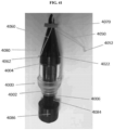
- the apparatus 4000 can also be optionally loaded using a loading apparatus 4080 similar to loading apparatus 200.
- the loading apparatus 4080 has a conical head 4082, a shaft 4084, and a nut 4086.
- the loading apparatus can thus be attached to the apparatus 4000 in a similar manner to loading apparatus 200 attaching to band ligation apparatus 1000, and the ligation bands 4070 can be loaded onto apparatus 4000 in the same manner as discussed above.
Landscapes
- Health & Medical Sciences (AREA)
- Life Sciences & Earth Sciences (AREA)
- Surgery (AREA)
- Molecular Biology (AREA)
- General Health & Medical Sciences (AREA)
- Veterinary Medicine (AREA)
- Engineering & Computer Science (AREA)
- Biomedical Technology (AREA)
- Heart & Thoracic Surgery (AREA)
- Medical Informatics (AREA)
- Public Health (AREA)
- Animal Behavior & Ethology (AREA)
- Nuclear Medicine, Radiotherapy & Molecular Imaging (AREA)
- Reproductive Health (AREA)
- Vascular Medicine (AREA)
- Physics & Mathematics (AREA)
- Biophysics (AREA)
- Optics & Photonics (AREA)
- Pathology (AREA)
- Radiology & Medical Imaging (AREA)
- Surgical Instruments (AREA)
Claims (15)
- Bandligationsvorrichtung, umfassend:einen länglichen Zylinder, der ein proximales Ende, das mit einem Endoskop zusammenfügbar ist, ein distales Ende und ein Innenlumen, das sich durch das proximale und das distale Ende erstreckt, aufweist;eine Vielzahl von Bändern, die in Umfangsrichtung um eine Außenfläche des länglichen Zylinders herum angeordnet ist; undeine erste und eine zweite Korde, wobei sich jede Korde von einem abschließenden hinteren Ende distal entlang der Außenfläche des länglichen Zylinders, um das distale Ende herum und proximal durch das Innenlumen erstreckt, sodass sich ein vorderes Ende der Korde proximal von dem Innenlumen des länglichen Zylinders erstreckt,und wobei die erste und die zweite Korde eine Vielzahl von darauf unbeweglich angeordneten und zwischen jedem der Vielzahl von Bändern positionierten Wülsten zum Entfalten der Bänder aufweisen, dadurch gekennzeichnet, dass die erste und die zweite Korde einander überlappen, um entlang der Außenfläche ein Kreuzmuster zu bilden.
- Vorrichtung nach Anspruch 1, wobei ein proximales Zurückziehen des vorderen Endes jeder der ersten und zweiten Korde dazu konfiguriert ist, zu bewirken, dass die Vielzahl von Wülsten die Vielzahl von Bändern nacheinander distal vorschiebt, um die Bänder um ein in das Innenlumen des länglichen Zylinders gezogenes Gewebe zu entfalten.
- Vorrichtung nach Anspruch 1 oder 2, wobei der längliche Zylinder eine horizontale Ebene aufweist, die sich entlang einer Längsachse des Innenlumens und durch das distale Ende erstreckt, die eine erste und eine zweite Seite des länglichen Zylinders definiert, und das Kreuzmuster nur an einer von der ersten und der zweiten Seite des länglichen Zylinders gebildet ist.
- Vorrichtung nach einem der vorstehenden Ansprüche, wobei das Kreuzmuster der ersten und der zweiten Korde beinhaltet, dass die erste und die zweite Korde an jedem Überlappungspunkt entlang der Außenfläche umeinander geschlungen sind.
- Vorrichtung nach einem der vorstehenden Ansprüche, wobei jeder Überlappungspunkt durch die erste und die zweite Korde entlang der Außenfläche in einer Linie auf der Außenfläche angeordnet ist, die sich parallel zu einer Längsachse des Innenlumens erstreckt.
- Vorrichtung nach einem der vorstehenden Ansprüche, wobei das distale Ende des länglichen Zylinders eine abschließende Endfläche aufweist, die sich in einem schrägen Winkel zu einer Längsachse des Innenlumens erstreckt, die abschließende Endfläche einen am weitesten distal gelegenen Punkt, einen am weitesten proximal gelegenen Punkt und einen ersten und einen gegenüberliegenden zweiten Mittelpunkt, die äquidistant zwischen dem am weitesten distal gelegenen und dem am weitesten proximal gelegenen Punkt positioniert sind, aufweist und der längliche Zylinder eine horizontale Ebene aufweist, die sich entlang der Längsachse des Innenlumens und durch den ersten und den gegenüberliegenden zweiten Mittelpunkt erstreckt, um ein erstes horizontales Segment des länglichen Zylinders einschließlich des am weitesten distal gelegenen Punktes und ein zweites horizontales Segment des länglichen Zylinders einschließlich des am weitesten proximal gelegenen Punktes zu definieren, wobei optional das abschließende hintere Ende jeder Korde auf dem ersten horizontalen Segment des länglichen Zylinders positioniert ist und wobei sich jede Korde distal von dem abschließenden hinteren Ende entlang nur des ersten horizontalen Segments auf der Außenfläche des länglichen Zylinders erstreckt.
- Vorrichtung nach einem der vorstehenden Ansprüche, wobei der längliche Zylinder mindestens eine daran angrenzend an das distale Ende gebildete Aussparung beinhaltet, wobei die mindestens eine Aussparung dazu konfiguriert ist, ein Band während des Entfaltens der Bänder zu platzieren.
- Vorrichtung nach Anspruch 1, wobei die Außenfläche des länglichen Zylinders mindestens eine Lippe aufweist, die angrenzend an das distale Ende des länglichen Zylinders gebildet ist, die dazu konfiguriert ist, in jedem der Vielzahl von Bändern einzugreifen und dessen Entfaltung zu verzögern.
- Vorrichtung nach Anspruch 1, wobei der längliche Zylinder mindestens einen gewebestoppenden Vorsprung aufweist, der von einer inneren Seitenwand des Innenlumens radial nach innen vorsteht.
- Bandligationseinrichtung, umfassend:einen hohlen länglichen Zylinder, der ein proximales Ende und ein distales Ende mit einer Endfläche aufweist; eine erste und eine zweite Korde, die sich durch den hohlen länglichen Zylinder, um die Endfläche herum und entlang einer Außenfläche des hohlen länglichen Zylinders erstrecken, wobei die erste und die zweite Korde eine Vielzahl von unbeweglich darauf angeordneten Wülsten aufweisen; undeine Vielzahl von Bändern, die in Umfangsrichtung um den hohlen länglichen Zylinder und die erste und die zweite Korde angeordnet ist, wobei die Vielzahl von Bändern axial entlang dieser beabstandet ist, wobei mindestens einer der Vielzahl von Wülsten an jeder der ersten und der zweiten Korde zwischen jedem der Vielzahl von Bändern zum Entfalten der Bänder positioniert ist; wobei die erste und die zweite Korde zwischen jedem der Vielzahl von Bändern entlang der Außenfläche ineinander eingreifen.
- Einrichtung nach Anspruch 10, wobei die erste und die zweite Korde beim Eingriff miteinander verdrillt sind und/oder wobei die erste und die zweite Korde entlang der Außenfläche des hohlen länglichen Zylinders in einer ungefähr geraden Linie parallel zu einer Längsachse des hohlen länglichen Zylinders ineinander eingreifen.
- Einrichtung nach Anspruch 10 oder 11, wobei die Endfläche des hohlen länglichen Zylinders einen schrägen Winkel oder einen senkrechten Winkel relativ zu einer Längsachse des hohlen länglichen Zylinders aufweist.
- Einrichtung nach Anspruch 10, 11 oder 12, wobei der hohle längliche Zylinder mindestens eine Leiste aufweist, die von einer inneren Seitenwand des hohlen länglichen Zylinders radial nach innen vorsteht.
- Bandligationseinrichtung nach einem der Ansprüche 10 bis 13, wobei ein proximales Zurückziehen des vorderen Endes jeder der ersten und der zweiten Korde durch den hohlen länglichen Zylinder dazu konfiguriert ist, zu bewirken, dass die Vielzahl von Wülsten die Vielzahl von Bändern nacheinander distal vorschiebt, um die Bänder um ein in das Innenlumen des länglichen Zylinders gezogenes Gewebe zu entfalten.
- Verfahren zum Laden einer Vielzahl von Bändern auf einen Ligationszylinder, umfassend:Positionieren eines ersten Wulstes an einem abschließenden Ende einer ersten Korde an einer ersten Stelle auf einer Außenfläche eines Ligationszylinders und Positionieren eines zweiten Wulstes an einer zweiten Korde an einer zweiten Stelle auf der Außenfläche des Ligationszylinders, wobei die erste und die zweite Stelle von einem distalen Ende des Ligationszylinders äquidistant relativ zueinander beabstandet sind und auf dem Ligationszylinder in Umfangsrichtung voneinander beabstandet sind;Vorschieben eines ersten Bandes auf den Ligationszylinder, um das erste Band distal benachbart zu dem ersten und dem zweiten Wulst zu positionieren;nach dem Vorschieben des ersten Bandes auf den Ligationszylinder, Kreuzen der ersten und der zweiten Korde mindestens einmal;Positionieren eines dritten Wulstes an der ersten Korde in Längsrichtung distal zu einem von dem ersten und zweiten Wulst und Positionieren eines vierten Wulstes an der zweiten Korde in Längsrichtung distal zu dem anderen von dem ersten und zweiten Wulst; undVorschieben eines zweiten Bandes auf den endoskopischen Zylinder, um das zweite Band distal benachbart zu dem dritten und vierten Wulst zu positionieren; optional ferner umfassend:nach dem Vorschieben des zweiten Bandes auf den Ligationszylinder, Kreuzen der ersten und der zweiten Korde mindestens einmal;Positionieren eines fünften Wulstes an der ersten Korde in Längsrichtung distal zu einem von dem dritten und vierten Wulst und Positionieren eines sechsten Wulstes an der zweiten Korde in Längsrichtung distal zu dem anderen von dem dritten und vierten Wulst; undVorschieben eines dritten Bandes auf den endoskopischen Zylinder, um das dritte Band distal benachbart zu dem fünften und sechsten Wulst zu positionieren; und wobei optional das mindestens einmalige Kreuzen der ersten und der zweiten Korde das mindestens einmalige Verdrillen der ersten und der zweiten Korde beinhaltet.
Applications Claiming Priority (2)
| Application Number | Priority Date | Filing Date | Title |
|---|---|---|---|
| US201862650828P | 2018-03-30 | 2018-03-30 | |
| PCT/US2019/024849 WO2019191595A1 (en) | 2018-03-30 | 2019-03-29 | Criss-cross cords for band ligation |
Publications (3)
| Publication Number | Publication Date |
|---|---|
| EP3773253A1 EP3773253A1 (de) | 2021-02-17 |
| EP3773253A4 EP3773253A4 (de) | 2021-12-15 |
| EP3773253B1 true EP3773253B1 (de) | 2023-03-22 |
Family
ID=68058485
Family Applications (1)
| Application Number | Title | Priority Date | Filing Date |
|---|---|---|---|
| EP19774335.4A Active EP3773253B1 (de) | 2018-03-30 | 2019-03-29 | Kreuzkorde für bandligation |
Country Status (3)
| Country | Link |
|---|---|
| US (1) | US11684370B2 (de) |
| EP (1) | EP3773253B1 (de) |
| WO (1) | WO2019191595A1 (de) |
Families Citing this family (1)
| Publication number | Priority date | Publication date | Assignee | Title |
|---|---|---|---|---|
| EP3773253B1 (de) | 2018-03-30 | 2023-03-22 | United States Endoscopy Group, Inc. | Kreuzkorde für bandligation |
Family Cites Families (18)
| Publication number | Priority date | Publication date | Assignee | Title |
|---|---|---|---|---|
| US6007551A (en) * | 1993-02-23 | 1999-12-28 | Wilson-Cook Medical Inc. | Endoscopic ligating apparatus |
| US5462559A (en) * | 1993-02-23 | 1995-10-31 | Ahmed; Munir | Endoscopic ligating instrument |
| US5624453A (en) * | 1993-02-23 | 1997-04-29 | Wilson-Cook Medical, Inc. | Endoscopic ligating instrument |
| US5320630A (en) * | 1993-02-23 | 1994-06-14 | Munir Ahmed | Endoscopic ligating instrument for applying elastic bands |
| US5398844A (en) * | 1994-01-31 | 1995-03-21 | Boston Scientific Corporation | Multiple ligating band dispenser |
| US5857585A (en) * | 1996-05-28 | 1999-01-12 | Act Medical, Inc. | Ligating band dispenser |
| US6235040B1 (en) * | 1998-09-21 | 2001-05-22 | Scimed Life Systems, Inc. | Single pull wire multiple band ligator |
| JP4578632B2 (ja) * | 2000-07-05 | 2010-11-10 | オリンパス株式会社 | 内視鏡用器具 |
| US6974466B2 (en) | 2000-12-06 | 2005-12-13 | Wilson-Cook Medical Inc. | Ligating band delivery apparatus |
| WO2006119762A1 (en) | 2005-05-09 | 2006-11-16 | Scandimed International A.S. | Ligator |
| JP2009536083A (ja) | 2006-05-03 | 2009-10-08 | インディアナ・ユニバーシティ・リサーチ・アンド・テクノロジー・コーポレーション | 食道及び他の体内管腔を再構築する方法と装置 |
| AU2008240316B2 (en) | 2007-04-13 | 2013-08-29 | Cook Medical Technologies Llc | Endoscopic barrel with connector |
| US20130274766A1 (en) | 2012-04-16 | 2013-10-17 | Boston Scientific Scimed, Inc. | Medical device with external actuation line |
| US9402631B2 (en) * | 2012-11-19 | 2016-08-02 | Endochoice, Inc. | Multiple band endoscopic ligation device |
| US10105143B2 (en) * | 2013-06-05 | 2018-10-23 | Boston Scientific Scimed, Inc. | Cap with band deployment features |
| EP3223720B1 (de) | 2014-11-27 | 2021-07-07 | Intelligent Endoscopy LLC | Gewebeligaturvorrichtung mit rotierender spulenanordnung und ventilanordnung |
| USD859659S1 (en) | 2018-01-26 | 2019-09-10 | Intelligent Endoscopy Llc | Ligation band |
| EP3773253B1 (de) | 2018-03-30 | 2023-03-22 | United States Endoscopy Group, Inc. | Kreuzkorde für bandligation |
-
2019
- 2019-03-29 EP EP19774335.4A patent/EP3773253B1/de active Active
- 2019-03-29 WO PCT/US2019/024849 patent/WO2019191595A1/en not_active Ceased
- 2019-03-29 US US17/043,150 patent/US11684370B2/en active Active
Also Published As
| Publication number | Publication date |
|---|---|
| US11684370B2 (en) | 2023-06-27 |
| EP3773253A1 (de) | 2021-02-17 |
| WO2019191595A1 (en) | 2019-10-03 |
| EP3773253A4 (de) | 2021-12-15 |
| US20210145443A1 (en) | 2021-05-20 |
Similar Documents
| Publication | Publication Date | Title |
|---|---|---|
| CN105451668B (zh) | 具有环套布置特征的帽 | |
| US8506477B2 (en) | System and method for endoscopic treatment of tissue | |
| US8974474B2 (en) | Ligator and method of use | |
| US9345539B2 (en) | Treatment device | |
| CN110461249B (zh) | 用于影响组织结构移动的系统和方法 | |
| US11259833B2 (en) | Resection devices and related methods of deployment | |
| US20140357946A1 (en) | Tissue spreader for accessing papilla, and related methods of use | |
| US10820905B2 (en) | Tissue ligation apparatus with a rotating spool assembly and a valve assembly | |
| US20210022746A1 (en) | System, device and method for treatment of hemorrhoids | |
| JP2020523177A (ja) | 組織クリップ適用取付セット/後付セット | |
| US20180028180A1 (en) | Helical Tissue Anchor Device and Delivery System | |
| US9795386B2 (en) | Multiple band endoscopic ligation device | |
| AU2006284726C1 (en) | Peg tube with wireless pull tip | |
| US20150099931A1 (en) | Endoscope anchoring device | |
| EP3773253B1 (de) | Kreuzkorde für bandligation | |
| US10376283B2 (en) | Medical port | |
| CN115349989A (zh) | 用于递送和展开胃阻塞装置的装置、组件和系统及其操作方法 | |
| JP2010081963A (ja) | クリップ処置具用操作ハンドルおよび連発式クリップ処置具 |
Legal Events
| Date | Code | Title | Description |
|---|---|---|---|
| STAA | Information on the status of an ep patent application or granted ep patent |
Free format text: STATUS: THE INTERNATIONAL PUBLICATION HAS BEEN MADE |
|
| PUAI | Public reference made under article 153(3) epc to a published international application that has entered the european phase |
Free format text: ORIGINAL CODE: 0009012 |
|
| STAA | Information on the status of an ep patent application or granted ep patent |
Free format text: STATUS: REQUEST FOR EXAMINATION WAS MADE |
|
| 17P | Request for examination filed |
Effective date: 20201029 |
|
| AK | Designated contracting states |
Kind code of ref document: A1 Designated state(s): AL AT BE BG CH CY CZ DE DK EE ES FI FR GB GR HR HU IE IS IT LI LT LU LV MC MK MT NL NO PL PT RO RS SE SI SK SM TR |
|
| AX | Request for extension of the european patent |
Extension state: BA ME |
|
| DAV | Request for validation of the european patent (deleted) | ||
| DAX | Request for extension of the european patent (deleted) | ||
| A4 | Supplementary search report drawn up and despatched |
Effective date: 20211112 |
|
| RAP1 | Party data changed (applicant data changed or rights of an application transferred) |
Owner name: UNITED STATES ENDOSCOPY GROUP, INC. |
|
| RIC1 | Information provided on ipc code assigned before grant |
Ipc: A61B 17/3205 20060101ALN20211108BHEP Ipc: A61B 17/32 20060101ALN20211108BHEP Ipc: A61B 17/22 20060101ALN20211108BHEP Ipc: A61B 1/273 20060101ALN20211108BHEP Ipc: A61B 1/012 20060101ALN20211108BHEP Ipc: A61B 17/12 20060101AFI20211108BHEP |
|
| GRAP | Despatch of communication of intention to grant a patent |
Free format text: ORIGINAL CODE: EPIDOSNIGR1 |
|
| STAA | Information on the status of an ep patent application or granted ep patent |
Free format text: STATUS: GRANT OF PATENT IS INTENDED |
|
| RIC1 | Information provided on ipc code assigned before grant |
Ipc: A61B 17/3205 20060101ALN20220927BHEP Ipc: A61B 17/32 20060101ALN20220927BHEP Ipc: A61B 17/22 20060101ALN20220927BHEP Ipc: A61B 1/273 20060101ALN20220927BHEP Ipc: A61B 1/012 20060101ALN20220927BHEP Ipc: A61B 17/12 20060101AFI20220927BHEP |
|
| INTG | Intention to grant announced |
Effective date: 20221102 |
|
| GRAS | Grant fee paid |
Free format text: ORIGINAL CODE: EPIDOSNIGR3 |
|
| GRAA | (expected) grant |
Free format text: ORIGINAL CODE: 0009210 |
|
| STAA | Information on the status of an ep patent application or granted ep patent |
Free format text: STATUS: THE PATENT HAS BEEN GRANTED |
|
| AK | Designated contracting states |
Kind code of ref document: B1 Designated state(s): AL AT BE BG CH CY CZ DE DK EE ES FI FR GB GR HR HU IE IS IT LI LT LU LV MC MK MT NL NO PL PT RO RS SE SI SK SM TR |
|
| REG | Reference to a national code |
Ref country code: GB Ref legal event code: FG4D |
|
| REG | Reference to a national code |
Ref country code: CH Ref legal event code: EP |
|
| REG | Reference to a national code |
Ref country code: DE Ref legal event code: R096 Ref document number: 602019026703 Country of ref document: DE |
|
| REG | Reference to a national code |
Ref country code: IE Ref legal event code: FG4D |
|
| REG | Reference to a national code |
Ref country code: AT Ref legal event code: REF Ref document number: 1554821 Country of ref document: AT Kind code of ref document: T Effective date: 20230415 |
|
| P01 | Opt-out of the competence of the unified patent court (upc) registered |
Effective date: 20230513 |
|
| REG | Reference to a national code |
Ref country code: LT Ref legal event code: MG9D |
|
| REG | Reference to a national code |
Ref country code: NL Ref legal event code: MP Effective date: 20230322 |
|
| PG25 | Lapsed in a contracting state [announced via postgrant information from national office to epo] |
Ref country code: RS Free format text: LAPSE BECAUSE OF FAILURE TO SUBMIT A TRANSLATION OF THE DESCRIPTION OR TO PAY THE FEE WITHIN THE PRESCRIBED TIME-LIMIT Effective date: 20230322 Ref country code: NO Free format text: LAPSE BECAUSE OF FAILURE TO SUBMIT A TRANSLATION OF THE DESCRIPTION OR TO PAY THE FEE WITHIN THE PRESCRIBED TIME-LIMIT Effective date: 20230622 Ref country code: LV Free format text: LAPSE BECAUSE OF FAILURE TO SUBMIT A TRANSLATION OF THE DESCRIPTION OR TO PAY THE FEE WITHIN THE PRESCRIBED TIME-LIMIT Effective date: 20230322 Ref country code: LT Free format text: LAPSE BECAUSE OF FAILURE TO SUBMIT A TRANSLATION OF THE DESCRIPTION OR TO PAY THE FEE WITHIN THE PRESCRIBED TIME-LIMIT Effective date: 20230322 Ref country code: HR Free format text: LAPSE BECAUSE OF FAILURE TO SUBMIT A TRANSLATION OF THE DESCRIPTION OR TO PAY THE FEE WITHIN THE PRESCRIBED TIME-LIMIT Effective date: 20230322 |
|
| REG | Reference to a national code |
Ref country code: AT Ref legal event code: MK05 Ref document number: 1554821 Country of ref document: AT Kind code of ref document: T Effective date: 20230322 |
|
| PG25 | Lapsed in a contracting state [announced via postgrant information from national office to epo] |
Ref country code: SE Free format text: LAPSE BECAUSE OF FAILURE TO SUBMIT A TRANSLATION OF THE DESCRIPTION OR TO PAY THE FEE WITHIN THE PRESCRIBED TIME-LIMIT Effective date: 20230322 Ref country code: NL Free format text: LAPSE BECAUSE OF FAILURE TO SUBMIT A TRANSLATION OF THE DESCRIPTION OR TO PAY THE FEE WITHIN THE PRESCRIBED TIME-LIMIT Effective date: 20230322 Ref country code: GR Free format text: LAPSE BECAUSE OF FAILURE TO SUBMIT A TRANSLATION OF THE DESCRIPTION OR TO PAY THE FEE WITHIN THE PRESCRIBED TIME-LIMIT Effective date: 20230623 Ref country code: FI Free format text: LAPSE BECAUSE OF FAILURE TO SUBMIT A TRANSLATION OF THE DESCRIPTION OR TO PAY THE FEE WITHIN THE PRESCRIBED TIME-LIMIT Effective date: 20230322 |
|
| PG25 | Lapsed in a contracting state [announced via postgrant information from national office to epo] |
Ref country code: SM Free format text: LAPSE BECAUSE OF FAILURE TO SUBMIT A TRANSLATION OF THE DESCRIPTION OR TO PAY THE FEE WITHIN THE PRESCRIBED TIME-LIMIT Effective date: 20230322 Ref country code: RO Free format text: LAPSE BECAUSE OF FAILURE TO SUBMIT A TRANSLATION OF THE DESCRIPTION OR TO PAY THE FEE WITHIN THE PRESCRIBED TIME-LIMIT Effective date: 20230322 Ref country code: PT Free format text: LAPSE BECAUSE OF FAILURE TO SUBMIT A TRANSLATION OF THE DESCRIPTION OR TO PAY THE FEE WITHIN THE PRESCRIBED TIME-LIMIT Effective date: 20230724 Ref country code: ES Free format text: LAPSE BECAUSE OF FAILURE TO SUBMIT A TRANSLATION OF THE DESCRIPTION OR TO PAY THE FEE WITHIN THE PRESCRIBED TIME-LIMIT Effective date: 20230322 Ref country code: EE Free format text: LAPSE BECAUSE OF FAILURE TO SUBMIT A TRANSLATION OF THE DESCRIPTION OR TO PAY THE FEE WITHIN THE PRESCRIBED TIME-LIMIT Effective date: 20230322 Ref country code: AT Free format text: LAPSE BECAUSE OF FAILURE TO SUBMIT A TRANSLATION OF THE DESCRIPTION OR TO PAY THE FEE WITHIN THE PRESCRIBED TIME-LIMIT Effective date: 20230322 |
|
| REG | Reference to a national code |
Ref country code: CH Ref legal event code: PL |
|
| PG25 | Lapsed in a contracting state [announced via postgrant information from national office to epo] |
Ref country code: SK Free format text: LAPSE BECAUSE OF FAILURE TO SUBMIT A TRANSLATION OF THE DESCRIPTION OR TO PAY THE FEE WITHIN THE PRESCRIBED TIME-LIMIT Effective date: 20230322 Ref country code: PL Free format text: LAPSE BECAUSE OF FAILURE TO SUBMIT A TRANSLATION OF THE DESCRIPTION OR TO PAY THE FEE WITHIN THE PRESCRIBED TIME-LIMIT Effective date: 20230322 Ref country code: IS Free format text: LAPSE BECAUSE OF FAILURE TO SUBMIT A TRANSLATION OF THE DESCRIPTION OR TO PAY THE FEE WITHIN THE PRESCRIBED TIME-LIMIT Effective date: 20230722 |
|
| REG | Reference to a national code |
Ref country code: BE Ref legal event code: MM Effective date: 20230331 |
|
| PG25 | Lapsed in a contracting state [announced via postgrant information from national office to epo] |
Ref country code: LU Free format text: LAPSE BECAUSE OF NON-PAYMENT OF DUE FEES Effective date: 20230329 |
|
| REG | Reference to a national code |
Ref country code: DE Ref legal event code: R097 Ref document number: 602019026703 Country of ref document: DE |
|
| PG25 | Lapsed in a contracting state [announced via postgrant information from national office to epo] |
Ref country code: MC Free format text: LAPSE BECAUSE OF FAILURE TO SUBMIT A TRANSLATION OF THE DESCRIPTION OR TO PAY THE FEE WITHIN THE PRESCRIBED TIME-LIMIT Effective date: 20230322 |
|
| REG | Reference to a national code |
Ref country code: IE Ref legal event code: MM4A |
|
| PLBE | No opposition filed within time limit |
Free format text: ORIGINAL CODE: 0009261 |
|
| STAA | Information on the status of an ep patent application or granted ep patent |
Free format text: STATUS: NO OPPOSITION FILED WITHIN TIME LIMIT |
|
| PG25 | Lapsed in a contracting state [announced via postgrant information from national office to epo] |
Ref country code: SI Free format text: LAPSE BECAUSE OF FAILURE TO SUBMIT A TRANSLATION OF THE DESCRIPTION OR TO PAY THE FEE WITHIN THE PRESCRIBED TIME-LIMIT Effective date: 20230322 Ref country code: MC Free format text: LAPSE BECAUSE OF FAILURE TO SUBMIT A TRANSLATION OF THE DESCRIPTION OR TO PAY THE FEE WITHIN THE PRESCRIBED TIME-LIMIT Effective date: 20230322 Ref country code: LI Free format text: LAPSE BECAUSE OF NON-PAYMENT OF DUE FEES Effective date: 20230331 Ref country code: IE Free format text: LAPSE BECAUSE OF NON-PAYMENT OF DUE FEES Effective date: 20230329 Ref country code: DK Free format text: LAPSE BECAUSE OF FAILURE TO SUBMIT A TRANSLATION OF THE DESCRIPTION OR TO PAY THE FEE WITHIN THE PRESCRIBED TIME-LIMIT Effective date: 20230322 Ref country code: CZ Free format text: LAPSE BECAUSE OF FAILURE TO SUBMIT A TRANSLATION OF THE DESCRIPTION OR TO PAY THE FEE WITHIN THE PRESCRIBED TIME-LIMIT Effective date: 20230322 Ref country code: CH Free format text: LAPSE BECAUSE OF NON-PAYMENT OF DUE FEES Effective date: 20230331 |
|
| 26N | No opposition filed |
Effective date: 20240102 |
|
| PG25 | Lapsed in a contracting state [announced via postgrant information from national office to epo] |
Ref country code: BE Free format text: LAPSE BECAUSE OF NON-PAYMENT OF DUE FEES Effective date: 20230331 |
|
| PG25 | Lapsed in a contracting state [announced via postgrant information from national office to epo] |
Ref country code: BG Free format text: LAPSE BECAUSE OF FAILURE TO SUBMIT A TRANSLATION OF THE DESCRIPTION OR TO PAY THE FEE WITHIN THE PRESCRIBED TIME-LIMIT Effective date: 20230322 |
|
| PG25 | Lapsed in a contracting state [announced via postgrant information from national office to epo] |
Ref country code: BG Free format text: LAPSE BECAUSE OF FAILURE TO SUBMIT A TRANSLATION OF THE DESCRIPTION OR TO PAY THE FEE WITHIN THE PRESCRIBED TIME-LIMIT Effective date: 20230322 |
|
| PG25 | Lapsed in a contracting state [announced via postgrant information from national office to epo] |
Ref country code: CY Free format text: LAPSE BECAUSE OF FAILURE TO SUBMIT A TRANSLATION OF THE DESCRIPTION OR TO PAY THE FEE WITHIN THE PRESCRIBED TIME-LIMIT; INVALID AB INITIO Effective date: 20190329 |
|
| PG25 | Lapsed in a contracting state [announced via postgrant information from national office to epo] |
Ref country code: HU Free format text: LAPSE BECAUSE OF FAILURE TO SUBMIT A TRANSLATION OF THE DESCRIPTION OR TO PAY THE FEE WITHIN THE PRESCRIBED TIME-LIMIT; INVALID AB INITIO Effective date: 20190329 |
|
| PG25 | Lapsed in a contracting state [announced via postgrant information from national office to epo] |
Ref country code: TR Free format text: LAPSE BECAUSE OF FAILURE TO SUBMIT A TRANSLATION OF THE DESCRIPTION OR TO PAY THE FEE WITHIN THE PRESCRIBED TIME-LIMIT Effective date: 20230322 |
|
| PGFP | Annual fee paid to national office [announced via postgrant information from national office to epo] |
Ref country code: GB Payment date: 20260327 Year of fee payment: 8 |
|
| PGFP | Annual fee paid to national office [announced via postgrant information from national office to epo] |
Ref country code: DE Payment date: 20260327 Year of fee payment: 8 |
|
| PGFP | Annual fee paid to national office [announced via postgrant information from national office to epo] |
Ref country code: IT Payment date: 20260319 Year of fee payment: 8 |
|
| PGFP | Annual fee paid to national office [announced via postgrant information from national office to epo] |
Ref country code: FR Payment date: 20260325 Year of fee payment: 8 |