EP3774148B1 - Scie sauteuse - Google Patents
Scie sauteuse Download PDFInfo
- Publication number
- EP3774148B1 EP3774148B1 EP19780821.5A EP19780821A EP3774148B1 EP 3774148 B1 EP3774148 B1 EP 3774148B1 EP 19780821 A EP19780821 A EP 19780821A EP 3774148 B1 EP3774148 B1 EP 3774148B1
- Authority
- EP
- European Patent Office
- Prior art keywords
- switch
- power tool
- axis
- drive system
- housing
- Prior art date
- Legal status (The legal status is an assumption and is not a legal conclusion. Google has not performed a legal analysis and makes no representation as to the accuracy of the status listed.)
- Active
Links
Images


Classifications
-
- B—PERFORMING OPERATIONS; TRANSPORTING
- B23—MACHINE TOOLS; METAL-WORKING NOT OTHERWISE PROVIDED FOR
- B23D—PLANING; SLOTTING; SHEARING; BROACHING; SAWING; FILING; SCRAPING; LIKE OPERATIONS FOR WORKING METAL BY REMOVING MATERIAL, NOT OTHERWISE PROVIDED FOR
- B23D49/00—Machines or devices for sawing with straight reciprocating saw blades, e.g. hacksaws
- B23D49/10—Hand-held or hand-operated sawing devices with straight saw blades
- B23D49/16—Hand-held or hand-operated sawing devices with straight saw blades actuated by electric or magnetic power or prime movers
- B23D49/162—Pad sawing devices
-
- B—PERFORMING OPERATIONS; TRANSPORTING
- B23—MACHINE TOOLS; METAL-WORKING NOT OTHERWISE PROVIDED FOR
- B23D—PLANING; SLOTTING; SHEARING; BROACHING; SAWING; FILING; SCRAPING; LIKE OPERATIONS FOR WORKING METAL BY REMOVING MATERIAL, NOT OTHERWISE PROVIDED FOR
- B23D59/00—Accessories specially designed for sawing machines or sawing devices
- B23D59/001—Measuring or control devices, e.g. for automatic control of work feed pressure on band saw blade
-
- B—PERFORMING OPERATIONS; TRANSPORTING
- B25—HAND TOOLS; PORTABLE POWER-DRIVEN TOOLS; MANIPULATORS
- B25F—COMBINATION OR MULTI-PURPOSE TOOLS NOT OTHERWISE PROVIDED FOR; DETAILS OR COMPONENTS OF PORTABLE POWER-DRIVEN TOOLS NOT PARTICULARLY RELATED TO THE OPERATIONS PERFORMED AND NOT OTHERWISE PROVIDED FOR
- B25F5/00—Details or components of portable power-driven tools not particularly related to the operations performed and not otherwise provided for
- B25F5/02—Construction of casings, bodies or handles
Definitions
- the present invention relates to power tools, and more specifically to jigsaws.
- US 2013/145631 A1 discloses a power tool according to the preamble of claim 1, and in particular describes a palm electric tool that includes a housing adapted for palm gripping, a base connected to the housing for contacting with a workpiece and supporting the palm electric tool, a motor with an output shaft arranged within the housing.
- the output shaft is substantially parallel to the base.
- a transmission mechanism is connected to the output shaft of the motor which includes a slide bar.
- the slide bar is capable of being moved in a direction perpendicular to the output of the motor, a blade is connected to the slide bar which is positioned substantially perpendicular to the output of the motor and the base.
- a battery pack for powering the motor is inserted into the housing. An inserting direction of the battery pack is substantially parallel to the output shaft of the motor.
- the battery pack is positioned between the motor and the base and partially overlapped with the motor in a direction perpendicular to the base.
- a power tool including a drive system and a housing at least partially supporting the drive system.
- the housing includes a base configured to support the power tool relative to a workpiece on which the power tool operates.
- the power tool includes a handle coupled to the housing.
- the handle defines a longitudinal axis and includes a first portion positioned between the longitudinal axis and the base and a second portion opposite the first portion along the longitudinal axis.
- the power tool includes an activation switch coupled to a side surface of the housing.
- the activation switch is slidable in a direction parallel with a switch axis that intersects the longitudinal axis from a deactivated state, in which the drive system is non-operable, to an activated state, in which the drive system is operable.
- the activation switch is slidable toward the second portion of the handle from an intersection point between the switch axis and the longitudinal axis.
- a power tool including a housing and a handle coupled to the housing.
- the handle is configured to be gripped by an operator to manipulate the power tool.
- the power tool also includes a drive system supported in one of the housing or the handle.
- the drive system includes a frame, a motor at least supported by the frame, and a transmission driven by the motor.
- the transmission is at least power tool operates.
- the power tool includes a handle coupled to the housing.
- the handle defines a longitudinal axis and includes a first portion positioned between the longitudinal axis and the base and a second portion opposite the first portion along the longitudinal axis.
- the power tool includes an activation switch coupled to a side surface of the housing.
- the activation switch is slidable in a direction parallel with a switch axis that intersects the longitudinal axis from a deactivated state, in which the drive system is non-operable, to an activated state, in which the drive system is operable.
- the activation switch is slidable toward the second portion of the handle from an intersection point between the switch axis and the longitudinal axis.
- the activation switch is a first activation switch
- the power tool further comprises a second activation switch coupled to another side surface of the housing, wherein the second activation switch is slidable parallel to the switch axis between a deactivated state, in which the drive system is non-operable, and an activated state, in which the drive system is operable
- FIG. 1 illustrates a power tool, such as a jigsaw 10, including a housing 14 having a handle 18, a battery 22 removably coupled to the handle 18 at a rear portion of the housing 14, a guide plate 26 pivotably coupled to the housing 14 and configured to contact a workpiece 28 ( FIG. 3 ) during a cutting operation, and a cutting blade 30 protruding from a front portion of the housing 14 and a lower surface of the guide plate or base 26.
- the jigsaw 10 includes a drive system 34 ( FIG. 4 ) powered by the battery 22 and operable to impart reciprocating motion to the cutting blade 30 for cutting the workpiece 28.
- the handle 18 defines a longitudinal axis 38 extending centrally through handle 18 with the longitudinal axis 38 oriented substantially parallel (e.g., within 10 degrees) to the workpiece 28 in which the guide plate 26 abuts. Moreover, the longitudinal axis 38 is substantially perpendicular to a blade axis 40-the blade axis 40 being substantially parallel to a central (vertical) axis of the housing 14-along which the cutting blade 30 generally reciprocates during a cutting operation.
- the handle 18 includes a first or lower portion 41 ( FIG. 3 ) positioned between the longitudinal axis 38 and the guide plate 26, and a second or upper portion 43 ( FIG. 3 ) positioned opposite the lower portion 41 along the longitudinal axis 38.
- the jigsaw 10 also includes gripping surfaces 42a, 42b disposed on the housing 14 and the handle 18, respectively, that are graspable by a user to operate and maneuver the jigsaw 10 relative to the workpiece 28.
- the gripping surfaces 42a, 42b in addition to the housing 14 and the handle 18, are composed of a non-conductive material (e.g., plastic with or without an elastomeric overmold). Such a non-conductive material electrically insulates the user in the event that the user inadvertently cuts an electrical wire during a cutting operation, thus inhibiting, or at least mitigating, an electrical shock.
- the gripping surface 42b on the handle 18 further includes a pair of recessed gripping portions 46a, 46b ( FIGS. 1 and 2 ) disposed on opposite sides of the longitudinal axis 38 and generally located proximate the intersection of the housing 14 and the handle 18.
- Each recessed gripping portion 46a, 46b is defined by a raised lip 50 that extends substantially around the periphery of the recessed gripping portions 46a, 46b and includes a step 52.
- the step 52 and the raised lip 50 define an indentation 53 that is formed into at least one of the housing 14 and the handle 18 with the indentations 53 sized to receive a thumb or a finger (e.g., the index finger or the middle finger) of a user to prevent the users' thumb/finger from inadvertently slipping out of the recessed gripping portions 46a, 46b.
- a thumb or a finger e.g., the index finger or the middle finger
- the jigsaw 10 further includes a first activation switch 54 ( FIG. 1 ) and a second activation switch 58 ( FIG. 2 ) in electrical communication with the drive system 34 to selectively supply power to the drive system 34 via the battery 22, discussed in more detail below.
- the first activation switch 54 is provided on a first lateral side 62 of the housing 14 adjacent the first recessed gripping portion 46a
- the second activation switch 58 is provided on a second lateral side 66-opposite the first lateral side 62-of the housing 14 adjacent the second recessed gripping portion 46b.
- the activation switches 54, 58 are located on opposite sides of the longitudinal axis 38.
- Both switches 54, 58 are slidable parallel to a switch axis 70, which is oriented at an acute angle A1 relative to the longitudinal axis 38 (e.g., the acute angle A1 is located entirely above the longitudinal axis 38; FIG. 3 ).
- the switch axis 70 intersects the longitudinal axis 38 and at least extends through the housing 14 such that the switch axis 70 is positioned between the first and second activation switches 54, 58.
- the angle A1 of the switch axis 70 is approximately 42 degrees relative to the longitudinal axis 38, as illustrated in FIG. 3 .
- the angle A1 of the switch axis 70 may be approximately 42 degrees ⁇ 22.5 degrees relative to the longitudinal axis 38.
- the angle A1 of the switch axis 70 may range from approximately 19.5 degrees to approximately 64.5 degrees relative to the longitudinal axis 38. In further embodiments, the angle A1 may range from approximately parallel to the longitudinal axis 38 to approximately 60 degrees relative to the longitudinal axis 38.
- the switch axis 70 is oriented at an oblique angle B1 relative to a linear central axis 74 that intersects the longitudinal axis 38 with which the recessed gripping portions 46a, 46b are aligned.
- the oblique angle B1 is less than 90 degrees (e.g., approximately 65 degrees), however, in other embodiments, the oblique angle B1 can be between about 50 degrees and about 80 degrees.
- the switch axis 70 of the illustrated embodiment is oriented at an acute angle C1 that is approximately 48 degrees from the blade axis 40. In other embodiments, the acute angle C1 is between about 25.5 degrees and about 70.5 degrees.
- the first and second activation switches 54, 58 are independently slidable between an activated state, in which the battery 22 supplies power to the drive system 34, and a non-activated state (i.e., a deactivated state), in which no power is supplied to the drive system 34.
- the activated state of the first activation switch 54 is shown in broken lines in FIG. 3 and the non-activated state of the first activation switch 54 is shown in solid lines in FIG. 3 .
- the activated state of the first activation switch 54 is positioned further from the guide plate 26 and the workpiece 28 in an upward direction 76 along the switch axis 70 than the non-activated state. The upward direction 76 moves away from the guide plate 26/workpiece 28 and above the longitudinal axis 38.
- the first activation switch 54 is slidable in the direction 76 and toward the upper portion 43 of the handle 18 from an intersection point 77 between the switch axis 70 and the longitudinal axis 38.
- the two states of the second activation switch 58 are arranged in a similar manner.
- the activated state and non-activated state of the switches 54, 58 can be switched such that the non-activated state of the activation switches 54, 58 is positioned further from the guide plate 26 in the direction 76 along the switch axis 70 than the activated state.
- the switches 54, 56 are configured as momentary switches that are biased toward the non-activated state, and that return to the non-activated state in response to being released by the user (after having been switched to the activated state).
- the switches 54, 56 can be momentary switches that are independently moveable along an axis substantially transverse to the longitudinal axis 38 (e.g., moveable in a direction into the housing 14 in the reference frame of FIG. 3 ).
- the drive system 34 of the jigsaw 10 is disposed within the housing 14 and the handle 18 adjacent the respective gripping surfaces 42a, 42b.
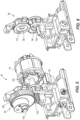
- the drive system 34 includes a motor 78, a transmission 82 driven by the motor 78 and having an output spindle 86 to which the cutting blade 30 is removably secured, and a frame 90 for mounting the motor 78 and the transmission 82 in the housing 14.
- the frame 90 is fixedly coupled within the housing 14.
- the frame 90 is composed of a non-conductive material (e.g., plastic).
- the frame 90 includes two apertures 94, 98 ( FIG. 6 ) that together support the motor 78 and the transmission 82.
- the first aperture 94 receives and supports a drive shaft 100 of the motor 78 which, in turn, supports a helical drive gear 102.
- the drive shaft 100-which is parallel to the longitudinal axis 38- is rotatably supported by the frame 90 via a first rotational support member 104 (e.g., a bushing, a radial bearing, etc.).
- the aperture 98 receives and supports a driven shaft 105 of a helical driven gear 106 of the transmission 82.
- the driven shaft 105-which is parallel to the drive shaft 100- is rotatably supported by the frame 90 via a second rotational support member 110 (e.g., a bushing, a radial bearing, etc.).
- the helical drive gear 102 intermeshes and drives the helical driven gear 106 of the transmission 82.
- the transmission 82 transfers the rotational motion of the helical driven gear 106 to a reciprocating motion of the spindle 86 to drive the cutting blade 30 in a reciprocating manner.
- a user may grasp the gripping surfaces 42a, 42b of the housing 14 and the handle 18 to maneuver the jigsaw 10 relative to the workpiece 28.
- the user may rest the jigsaw 10 on the workpiece 28 via the guide plate 26 and align the cutting blade 30 with the desired cut.
- the cutting blade 30 reciprocates along the blade axis 40 in response to the user sliding one of the first activation switch 54 or the second activation switch 58 into the activated state and then releasing the switch 54, 58 from the activated state.
- the user either slides the first activation switch 54 parallel to the switch axis 70 from the non-activated state to the activated state (e.g., moves the first activation switch 54 in the direction 76) or slides the second activation switch 58 parallel to the switch axis 70 from the non-activated state to the activated state (e.g., moving the second activation switch 58 in the direction 76), causing the motor 78 to drive the transmission 82 and reciprocate the cutting blade 30.
- both activation switches 54, 58 are not positioned in the activated state for the motor 78 and the transmission 82 to drive the cutting blade 30.
- activation switch 54, 58 By holding one activation switch 54, 58 in the activated state for a short period in time (e.g., 2 seconds, 3 seconds, etc.), continuous power from the battery 22 is supplied to the drive system 34 to cut the workpiece 28. Thereafter, the activation switch 54, 58 is released from the activated state to be biased into the non-activated state. Stated another way, power is supplied to the drive system 34 while the switches 54, 58 are in the non-activated state after one of the switches 54, 58 is moved into the activated state.
- a short period in time e.g., 2 seconds, 3 seconds, etc.
- one activation switch 54, 58 is simply moved back into the activated state from the non-activated state and released from the activated state (e.g., both switches 54, 58 are then positioned within the non-activated state and the jigsaw 10 is non-operable).
- the activation switches 54, 58 are conveniently located on the side surfaces 62, 66 of the housing 14 adjacent one of the recessed gripping portions 46a, 46b of the gripping surface 42b, the activation switches 54, 58 are easily accessible within an arc path of the user's thumb. As such, a user may simply slide the activation switches 54, 58 without altering or adjusting his or her grip of the jigsaw 10. Moreover, a user is able to use the jigsaw 10 for an extended period of time without experiencing discomfort. This is due, in part, to the non-heat conductive and non-electrically conductive material implemented on the gripping surfaces 42a, 42b, the housing 14, the handle 18, and the frame 90.
- the gripping surfaces 42a, 42b are maintained at a moderate temperature without overheating. Also, the user may experience additional comfort due to the ergonomic recessed gripping portion 46a, 46b and the raised lip 50 of the gripping surface 42b, as well as, the orientation of the activation switches 54, 58 (e.g., angles A1, B1).
Landscapes
- Engineering & Computer Science (AREA)
- Mechanical Engineering (AREA)
- Sawing (AREA)
Claims (10)
- Outil motorisé (10) comprenant ;un système d'entraînement (34) ;un logement (14) supportant au moins partiellement le système d'entraînement, le logement comportant une base (26) conçue pour supporter l'outil motorisé par rapport à une pièce de travail sur laquelle l'outil motorisé fonctionne ;une poignée (18) accouplée au logement, la poignée définissant un axe longitudinal (38) et comportant une première partie positionnée entre l'axe longitudinal et la base et une seconde partie opposée à la première partie le long de l'axe longitudinal ; etun commutateur d'activation (54) accouplé à une surface latérale du logement, le commutateur d'activation pouvant coulisser dans une direction parallèle à un axe de commutateur (70) qui croise l'axe longitudinal, d'un état désactivé, dans lequel le système d'entraînement est non fonctionnel, à un état activé, dans lequel le système d'entraînement est fonctionnel,dans lequel le commutateur d'activation peut coulisser en direction de la seconde partie de la poignée à partir d'un point d'intersection (77) entre l'axe de commutateur et l'axe longitudinal,dans lequel le commutateur d'activation est un premier commutateur d'activation,caractérisé en ce que l'outil motorisé comprend en outre un second commutateur d'activation (58) accouplé à une autre surface latérale du logement, etdans lequel le second commutateur d'activation peut coulisser parallèle à l'axe de commutateur entre un état désactivé, dans lequel le système d'entraînement est non fonctionnel, et un état activé, dans lequel le système d'entraînement est fonctionnel.
- Outil motorisé (10) selon la revendication 1, dans lequel l'axe de commutateur (70) est orienté selon un angle aigu par rapport à l'axe longitudinal de la poignée, et dans lequel l'angle aigu entre l'axe de commutateur et l'axe longitudinal (38) est compris entre 19,5 degrés et 64,5 degrés.
- Outil motorisé (10) selon la revendication 1, dans lequel la poignée (18) comporte une partie évidée (46a, 46b) positionnée adjacente au commutateur d'activation (54), et dans lequel la partie évidée est conçue pour recevoir une partie de la main d'un opérateur pour saisir l'outil motorisé.
- Outil motorisé (10) selon la revendication 3, dans lequel la partie évidée (46a 46b) est alignée sur un axe central (74) qui croise l'axe de commutateur (70) selon un angle aigu par rapport à l'axe de commutateur.
- Outil motorisé (10) selon la revendication 4, dans lequel l'angle aigu entre l'axe central et l'axe de commutateur est compris entre 50 degrés et 80 degrés.
- Outil motorisé (10) selon la revendication 3, dans lequel la partie évidée (46a, 46b) comporte un étagement (52) définissant au moins partiellement un renfoncement (53), et dans lequel le renfoncement est conçu pour recevoir le pouce ou un doigt d'un utilisateur pour saisir l'outil motorisé.
- Outil motorisé (10) selon la revendication 1, dans lequel le second commutateur d'activation (58) se déplace de l'état désactivé à l'état activé dans la direction parallèle à l'axe de commutateur (70).
- Outil motorisé (10) selon la revendication 7, dans lequel les premier et second commutateurs d'activation (54, 58) peuvent coulisser indépendamment l'un par rapport à l'autre.
- Outil motorisé (10) selon la revendication 8, dans lequel le système d'entraînement (34) est fonctionnel alors que le premier commutateur d'activation (54) est dans l'état activé et que le second commutateur d'activation (58) est dans l'état désactivé.
- Outil motorisé (10) selon la revendication 1, dans lequel le système d'entraînement (34) comporte un moteur (78) et une transmission (82) supportés au moins partiellement par un châssis (90), dans lequel le châssis est fixé à l'un parmi le logement (14) et la poignée (18), et dans lequel le châssis est composé d'un matériau non électroconducteur.
Applications Claiming Priority (2)
| Application Number | Priority Date | Filing Date | Title |
|---|---|---|---|
| US201862651776P | 2018-04-03 | 2018-04-03 | |
| PCT/US2019/023537 WO2019194987A1 (fr) | 2018-04-03 | 2019-03-22 | Scie sauteuse |
Publications (3)
| Publication Number | Publication Date |
|---|---|
| EP3774148A1 EP3774148A1 (fr) | 2021-02-17 |
| EP3774148A4 EP3774148A4 (fr) | 2021-12-15 |
| EP3774148B1 true EP3774148B1 (fr) | 2025-02-12 |
Family
ID=68057625
Family Applications (1)
| Application Number | Title | Priority Date | Filing Date |
|---|---|---|---|
| EP19780821.5A Active EP3774148B1 (fr) | 2018-04-03 | 2019-03-22 | Scie sauteuse |
Country Status (4)
| Country | Link |
|---|---|
| US (2) | US11014176B2 (fr) |
| EP (1) | EP3774148B1 (fr) |
| CN (1) | CN213646136U (fr) |
| WO (1) | WO2019194987A1 (fr) |
Families Citing this family (7)
| Publication number | Priority date | Publication date | Assignee | Title |
|---|---|---|---|---|
| WO2019194987A1 (fr) * | 2018-04-03 | 2019-10-10 | Milwaukee Electric Tool Corporation | Scie sauteuse |
| DE102019207973A1 (de) * | 2019-05-29 | 2020-12-03 | Robert Bosch Gmbh | Handwerkzeugmaschine |
| CN112238411B (zh) * | 2019-07-19 | 2024-02-20 | 株式会社牧田 | 电动工具及旋转工具 |
| CN113798589B (zh) * | 2020-06-16 | 2025-12-05 | 南京泉峰科技有限公司 | 电动工具 |
| CN113798590B (zh) * | 2020-06-16 | 2025-09-16 | 南京泉峰科技有限公司 | 电动工具 |
| EP4129547A4 (fr) * | 2020-06-16 | 2023-10-18 | Nanjing Chervon Industry Co., Ltd. | Outil électrique |
| EP4457045A1 (fr) * | 2021-12-30 | 2024-11-06 | Robert Bosch GmbH | Scie sauteuse comprenant des régions de liaison mutuellement espacées |
Citations (1)
| Publication number | Priority date | Publication date | Assignee | Title |
|---|---|---|---|---|
| JP3215304U (ja) * | 2017-12-28 | 2018-03-08 | 香山 恒夫 | 電気ドリル |
Family Cites Families (333)
| Publication number | Priority date | Publication date | Assignee | Title |
|---|---|---|---|---|
| US2320113A (en) | 1941-02-18 | 1943-05-25 | Black & Decker Mfg Co | Portable electric tool motor construction |
| US2306769A (en) | 1941-02-18 | 1942-12-29 | Black & Decker Mfg Co | Portable electric tool motor construction |
| US2352013A (en) * | 1943-09-10 | 1944-06-20 | Roth Ervin | Knife guard |
| US2781800A (en) | 1954-11-05 | 1957-02-19 | Walter A Papworth | Manually portable bayonet saw with oval stroke |
| US2931402A (en) | 1957-03-22 | 1960-04-05 | Walter A Papworth | Power driven reciprocable cutting tool |
| US2980218A (en) | 1958-03-20 | 1961-04-18 | Master Power Corp | Torque control for impact tool |
| US2949944A (en) | 1958-06-27 | 1960-08-23 | Oster Mfg Co John | Portable hand held saw |
| US3121813A (en) | 1960-11-15 | 1964-02-18 | Millers Falls Co | Electric power unit |
| US3225232A (en) | 1962-10-17 | 1965-12-21 | Singer Co | Variable speed portable tool |
| US3309484A (en) | 1965-12-27 | 1967-03-14 | Skil Corp | Trigger actuated switch device |
| US3388728A (en) | 1966-04-15 | 1968-06-18 | Martin Marietta Corp | Portable power tools |
| US3328613A (en) | 1966-10-26 | 1967-06-27 | Skil Corp | Speed control system for electrically powered tools of the trigger controlled type |
| US3491259A (en) | 1968-01-04 | 1970-01-20 | Stanley Works | Variable speed portable electric hand tool |
| DE1763455B1 (de) | 1968-05-31 | 1972-03-09 | Metabowerke Kg | Vorrichtung zur einstellung des sollwertes an einem elektroni schen drehzahlregler eines ein elektrowerkzeug antreibenden elektromotors |
| DE6934527U (de) | 1969-09-02 | 1969-12-18 | Metabowerke Kg | Kraftangetriebenes werkzeug mit waermeempfindlichem gehaeuse |
| US3536943A (en) | 1969-10-31 | 1970-10-27 | Rockwell Mfg Co | Electrically powered hand tool |
| BE791093A (fr) | 1971-12-30 | 1973-03-01 | Gardner Denver Co | Variateur automatique de vitesse d'outil |
| US3842328A (en) | 1972-03-01 | 1974-10-15 | Skil Corp | Speed control device with independent speed control and on-off operating members |
| DE2407601C2 (de) | 1974-02-16 | 1980-04-17 | Robert Bosch Gmbh, 7000 Stuttgart | Steuereinrichtung zur Absenkung der Drehzahl eines wechselstromgespeisten Reihenschlußmotors im Leerlaufbetrieb |
| US3965778A (en) | 1974-09-19 | 1976-06-29 | Standard Pressed Steel Co. | Multi-stage tightening system |
| DE7513910U (de) * | 1975-04-30 | 1976-11-04 | Scintilla Ag, Solothurn (Schweiz) | Zusatzgriff, insbesondere fuer kraftwerkzeuge |
| DE2629723C3 (de) | 1976-07-02 | 1980-07-03 | Scintilla Ag, Solothurn (Schweiz) | Handbetätigbare Einbauschaltvorrichtung für elektrische Maschinen |
| DE2650470C2 (de) | 1976-11-04 | 1984-03-22 | Eugen Lutz GmbH u. Co Maschinenfabrik, 7130 Mühlacker | Stichsäge |
| DE2654534A1 (de) | 1976-12-02 | 1978-06-08 | Bosch Gmbh Robert | Drehzahlregelung und -steuerung eines universalmotors |
| US4129240A (en) | 1977-07-05 | 1978-12-12 | Duo-Fast Corporation | Electric nailer |
| US4262421A (en) | 1978-08-11 | 1981-04-21 | Eugen Lutz Gmbh & Co. Maschinenfabrik | Keyhole saw |
| IT1166601B (it) | 1979-01-29 | 1987-05-05 | Star Utensili Elett | Dispositivo regolatore della velocita' di rotazione del motore elettrico di una macchina utensile |
| US4240204A (en) | 1979-06-19 | 1980-12-23 | Black & Decker Inc. | Jig saw |
| US4238884A (en) | 1979-06-19 | 1980-12-16 | Black & Decker Inc. | Orbital jig saw |
| DE2926111A1 (de) | 1979-06-28 | 1981-01-08 | Scintilla Ag | Elektrohandwerkzeug |
| US4342929A (en) | 1979-07-13 | 1982-08-03 | Black & Decker Inc. | Electric motor wherein low temperature polymeric housing supports heat dissipating portions through heat resisting polymeric bridging member |
| DE2933355A1 (de) | 1979-08-17 | 1981-03-26 | Scintilla Ag, Solothurn | Elektrohandwerkzeug |
| US4298072A (en) | 1979-08-31 | 1981-11-03 | Senco Products, Inc. | Control arrangement for electro-mechanical tool |
| DE3000452C2 (de) | 1980-01-08 | 1984-09-06 | Licentia Patent-Verwaltungs-Gmbh, 6000 Frankfurt | Getriebegehäuse für Elektrowerkzeuge |
| US4307325A (en) | 1980-01-28 | 1981-12-22 | Black & Decker Inc. | Digital control system for electric motors in power tools and the like |
| US4412158A (en) | 1980-02-21 | 1983-10-25 | Black & Decker Inc. | Speed control circuit for an electric power tool |
| US4504769A (en) | 1980-10-28 | 1985-03-12 | Makita Electric Works, Ltd. | Electrically-powered tool |
| US4348603A (en) | 1981-01-29 | 1982-09-07 | Black & Decker Inc. | Printed-circuit board and trigger-switch arrangement for a portable electric tool |
| JPS57146500A (en) | 1981-03-02 | 1982-09-09 | Japan Storage Battery Co Ltd | Controlling device for small-sized press |
| DE3240114A1 (de) | 1981-12-09 | 1983-06-16 | Black & Decker, Inc., 19711 Newark, Del. | Steuerschaltung fuer ein elektromagnetisch betaetigtes kraftwerkzeug, insbesondere eintreibgeraet |
| DE3214482C2 (de) | 1982-04-20 | 1988-10-20 | Kress-elektrik GmbH & Co, Elektromotorenfabrik, 7457 Bisingen | Verfahren und Schaltungsanordnung zur Steuerung der Drehzahl eines Elektromotors |
| DE3216446A1 (de) | 1982-05-03 | 1983-11-03 | Fa. Andreas Stihl, 7050 Waiblingen | Sicherheitseinrichtung an einem tragbaren, motorisch angetriebenen handgeraet |
| DE3318199A1 (de) | 1982-06-03 | 1984-11-22 | Licentia Patent-Verwaltungs-Gmbh, 6000 Frankfurt | Getriebegehaeuse fuer elektrowerkzeuge |
| IT1212535B (it) | 1982-10-26 | 1989-11-30 | Star Utensili Elett | Frizione elettronica a piu' livelli di intervento per utensili elettrici a velocita'selezionabile. |
| US4516324A (en) | 1982-11-01 | 1985-05-14 | Black & Decker Inc. | Modular housing system for a circular saw |
| JPS59163608A (ja) | 1983-03-08 | 1984-09-14 | Hitachi Koki Co Ltd | ジグソ− |
| DE3335237A1 (de) | 1983-09-29 | 1985-04-11 | Kress-elektrik GmbH & Co, Elektromotorenfabrik, 7457 Bisingen | Verfahren und vorrichtung zur regelung eines elektromotors, bei welchem die drehzahl im lastfreien leerlaufbetrieb automatisch abgesenkt wird |
| US4548248A (en) * | 1984-02-27 | 1985-10-22 | Riemann Herbert F | Handle for striking tool |
| ATE78951T1 (de) | 1985-04-01 | 1992-08-15 | Bsg Schalttechnik | Schalteranordnung. |
| US4628605A (en) | 1985-06-10 | 1986-12-16 | Porter-Cable Corporation | Orbital bayonet saw |
| DE3538942A1 (de) | 1985-10-31 | 1987-05-21 | Black & Decker Inc | Feldstecker fuer einen elektromotor |
| DE3538940A1 (de) | 1985-10-31 | 1987-05-07 | Black & Decker Inc | Verdrahtungsanordnung fuer den motor eines elektrowerkzeugs |
| SE461451B (sv) | 1987-01-27 | 1990-02-19 | Atlas Copco Ab | Maskinverktyg foer tvaastegsdragning av skruvfoerband |
| JP2520629B2 (ja) | 1987-04-06 | 1996-07-31 | 株式会社マキタ | 電動工具用起動制御装置 |
| US5115175A (en) | 1988-02-03 | 1992-05-19 | Hall Surgical | Drill having alternate mode control |
| JPS63176075U (fr) | 1988-04-28 | 1988-11-15 | ||
| GB8812292D0 (en) | 1988-05-24 | 1988-06-29 | Black & Decker Inc | Improvements in/relating to power tools |
| DE8808570U1 (de) | 1988-07-05 | 1988-09-08 | BSG-Schalttechnik GmbH & Co KG, 7460 Balingen | Vorrichtung mit Einschaltautomatik für ein Nebengerät bei Inbetriebnahme eines Hauptgerätes |
| DE3822633A1 (de) | 1988-07-05 | 1990-01-18 | Bsg Schalttechnik | Vorrichtung mit einschaltautomatik fuer ein nebengeraet bei inbetriebnahme eines hauptgeraetes |
| NL194021C (nl) | 1988-12-07 | 2001-04-03 | Capax B V | Schakelaar met mechanische begrenzing. |
| DE3843236A1 (de) | 1988-12-22 | 1990-06-28 | Bosch Gmbh Robert | Handkreissaege |
| US4940177A (en) | 1988-12-30 | 1990-07-10 | Jimena Carlos L | Electric stapler having electronic control circuit |
| US4964558A (en) | 1989-05-26 | 1990-10-23 | Sencorp | Electro-mechanical fastener driving tool |
| GB2235552B (en) | 1989-06-23 | 1993-06-16 | Nitto Kohki Co | Controller for boring apparatus |
| DE3923421A1 (de) | 1989-07-15 | 1991-01-24 | Kress Elektrik Gmbh & Co | Elektrischer universalmotor |
| DE3934950A1 (de) | 1989-10-20 | 1991-04-25 | Marquardt Gmbh | Drehzahlregler fuer elektromotoren von elektrowerkzeugen |
| US5017109A (en) | 1990-01-26 | 1991-05-21 | Ingersoll-Rand Company | Cylinder and housing assembly for pneumatic tool |
| US5154242A (en) | 1990-08-28 | 1992-10-13 | Matsushita Electric Works, Ltd. | Power tools with multi-stage tightening torque control |
| US5268622A (en) | 1991-06-27 | 1993-12-07 | Stryker Corporation | DC powered surgical handpiece having a motor control circuit |
| GB9126338D0 (en) | 1991-12-11 | 1992-02-12 | Glynwed Eng | Fastener applicator |
| US5203242A (en) | 1991-12-18 | 1993-04-20 | Hansson Gunnar C | Power tool for two-step tightening of screw joints |
| JP2800570B2 (ja) | 1992-07-16 | 1998-09-21 | 日立工機株式会社 | 自動穿孔機 |
| DE4306975A1 (de) | 1993-03-05 | 1994-09-08 | Bosch Gmbh Robert | Handwerkzeugmaschine |
| DE4309011A1 (de) | 1993-03-20 | 1994-09-22 | Marquardt Gmbh | Schaltungsanordnung zur Drehzahlregelung von Elektromotoren |
| DE9308698U1 (de) | 1993-06-11 | 1994-10-27 | Dolmar GmbH, 22045 Hamburg | Handarbeitsgerät mit einem Antrieb |
| US5440215A (en) | 1993-07-06 | 1995-08-08 | Black & Decker Inc. | Electrical power tool having a motor control circuit for increasing the effective torque output of the power tool |
| US6424799B1 (en) | 1993-07-06 | 2002-07-23 | Black & Decker Inc. | Electrical power tool having a motor control circuit for providing control over the torque output of the power tool |
| JP2568736Y2 (ja) | 1993-12-06 | 1998-04-15 | マックス株式会社 | 可搬形電動ステープル打機 |
| US5526460A (en) | 1994-04-25 | 1996-06-11 | Black & Decker Inc. | Impact wrench having speed control circuit |
| US5443276A (en) | 1994-07-22 | 1995-08-22 | S-B Power Tool Company | Self-locking blade holder |
| WO1996012591A1 (fr) | 1994-10-21 | 1996-05-02 | Senco Products, Inc. | Outil pneumatique de pose de fixations et sa commande electronique |
| JPH08141928A (ja) | 1994-11-16 | 1996-06-04 | Tonichi Seisakusho:Kk | ねじ締め制御信号検出方式 |
| JPH08163894A (ja) | 1994-12-05 | 1996-06-21 | Jidosha Denki Kogyo Co Ltd | モータ制御装置 |
| ATE183122T1 (de) | 1994-12-16 | 1999-08-15 | Ceka Elektrowerkzeuge Ag & Co | Pendelhubantrieb für stichsägen |
| DE19508925A1 (de) | 1995-03-13 | 1996-09-19 | Marquardt Gmbh | Elektrischer Schalter, insbesondere für Elektrohandwerkzeuge |
| DE19509539A1 (de) | 1995-03-16 | 1996-09-19 | Bosch Gmbh Robert | Stichsägemaschine |
| DE19509544A1 (de) | 1995-03-16 | 1996-09-26 | Scintilla Ag | Stichsäge |
| JPH08290312A (ja) | 1995-04-20 | 1996-11-05 | Hitachi Koki Co Ltd | 切削制御装置 |
| US7325315B2 (en) | 1995-06-09 | 2008-02-05 | Black & Decker Inc. | Clamping arrangement for receiving a saw blade in multiple orientations |
| US5738177A (en) | 1995-07-28 | 1998-04-14 | Black & Decker Inc. | Production assembly tool |
| US5798589A (en) | 1995-09-13 | 1998-08-25 | Zexel Corporation | Brushless motor having lubrication system for upper and lower bearings |
| NL1001299C2 (nl) | 1995-09-26 | 1997-03-28 | Skil Europ Bv | Verbeterde cirkelzaag. |
| US5664634A (en) * | 1995-10-23 | 1997-09-09 | Waxing Corporation Of America, Inc. | Power tool |
| US5747953A (en) | 1996-03-29 | 1998-05-05 | Stryker Corporation | Cordless, battery operated surical tool |
| DE19617477A1 (de) | 1996-05-02 | 1997-11-06 | Bosch Gmbh Robert | Elektrische Handschleifmaschine |
| JP3326548B2 (ja) | 1996-07-23 | 2002-09-24 | 株式会社マキタ | 切断機 |
| JP3516037B2 (ja) | 1996-08-09 | 2004-04-05 | オムロン株式会社 | 高周波用開閉器 |
| GB2322593B (en) | 1997-02-28 | 1999-05-05 | Bosch Gmbh Robert | Clamping mechanism for a power tool |
| JP3974218B2 (ja) | 1997-03-24 | 2007-09-12 | 株式会社共立 | 動力切断機 |
| CN2295295Y (zh) | 1997-04-24 | 1998-10-21 | 管康 | 电动工具软启动装置 |
| US5923145A (en) | 1997-08-15 | 1999-07-13 | S-B Power Tool Company | Controller for variable speed motor |
| JPH11164579A (ja) | 1997-11-27 | 1999-06-18 | Ryobi Ltd | 電動トリマ |
| JP3426150B2 (ja) | 1998-03-26 | 2003-07-14 | アスモ株式会社 | ブラシレスモータ、車両用空調装置の送風機用モータ、及びブラシレスモータの製造方法 |
| DE19833794A1 (de) | 1998-07-21 | 2000-01-27 | Black & Decker Inc | Handgeführtes Elektrowerkzeug, insbesondere Stichsäge |
| DE29819601U1 (de) | 1998-11-03 | 2000-03-09 | Scintilla Ag, Solothurn | Handwerkzeugmaschine |
| US6025683A (en) | 1998-12-23 | 2000-02-15 | Stryker Corporation | Motor control circuit for regulating a D.C. motor |
| US6536536B1 (en) | 1999-04-29 | 2003-03-25 | Stephen F. Gass | Power tools |
| CN2369805Y (zh) | 1999-05-12 | 2000-03-22 | 苏州塑料九厂 | 曲线锯传动摆动机构 |
| US6568089B1 (en) | 1999-06-04 | 2003-05-27 | Porter-Cable/Delta | Reciprocating saw having compact configuration and independent stability |
| US6353705B1 (en) | 1999-07-26 | 2002-03-05 | Makita Corporation | Speed control circuit of a direct current motor |
| USD426124S (en) | 1999-07-27 | 2000-06-06 | Makita Corporation | Portable electric jigsaw |
| DE19936119B4 (de) | 1999-07-31 | 2005-03-03 | Tts Tooltechnic Systems Ag & Co. Kg | Stichsäge |
| ES2192022T3 (es) | 1999-09-01 | 2003-09-16 | Ramachandran Ramarathnam | Util electrico portatil. |
| JP3673128B2 (ja) | 1999-11-16 | 2005-07-20 | 株式会社マキタ | プリセット速度実現スイッチ付き動力工具 |
| US6538403B2 (en) | 2000-01-07 | 2003-03-25 | Black & Decker Inc. | Brushless DC motor sensor control system and method |
| US7058291B2 (en) | 2000-01-07 | 2006-06-06 | Black & Decker Inc. | Brushless DC motor |
| US6975050B2 (en) | 2000-01-07 | 2005-12-13 | Black & Decker Inc. | Brushless DC motor |
| DE50015680D1 (de) | 2000-02-07 | 2009-08-13 | Ebm Papst St Georgen Gmbh & Co | Anordnung zur speisung eines verbrauchers mit nicht kontinuierliche stromaufnahme, insbesondere eines gleichstrommotors, aus einem gleichstromnetz |
| US6522041B1 (en) | 2000-03-08 | 2003-02-18 | Black & Decker Inc. | Permanent magnet motor flux rings |
| JP3995895B2 (ja) | 2000-05-16 | 2007-10-24 | 株式会社マキタ | 往復動切断工具のブレード取り付け装置 |
| US6491114B1 (en) | 2000-10-03 | 2002-12-10 | Npk Construction Equipment, Inc. | Slow start control for a hydraulic hammer |
| DE10053582A1 (de) | 2000-10-28 | 2002-05-16 | Bosch Gmbh Robert | Handwerkzeugmaschine mit einer Staubabsaugeinrichtung |
| US20020185514A1 (en) | 2000-12-22 | 2002-12-12 | Shane Adams | Control module for flywheel operated hand tool |
| US6796475B2 (en) | 2000-12-22 | 2004-09-28 | Senco Products, Inc. | Speed controller for flywheel operated hand tool |
| US6755336B2 (en) | 2000-12-22 | 2004-06-29 | Kevin A. Harper | Return mechanism for a cyclic tool |
| US6669072B2 (en) | 2000-12-22 | 2003-12-30 | Senco Products, Inc. | Flywheel operated nailer |
| US7103979B2 (en) | 2001-04-20 | 2006-09-12 | Hitachi Koki Co., Ltd. | Portable electric cutting device with blower mechanism |
| US6771043B2 (en) | 2001-05-09 | 2004-08-03 | Makita Corporation | Power tools |
| JP4248766B2 (ja) | 2001-05-23 | 2009-04-02 | 株式会社マキタ | 往復動切断工具 |
| US6508313B1 (en) | 2001-07-23 | 2003-01-21 | Snap-On Technologies, Inc. | Impact tool battery pack with acoustically-triggered timed impact shutoff |
| USD468983S1 (en) | 2001-10-03 | 2003-01-21 | Makita Corporation | Portable electric jigsaw |
| USD475264S1 (en) | 2001-10-11 | 2003-06-03 | Makita Corporation | Portable electric jigsaw |
| DE10161932A1 (de) | 2001-12-17 | 2003-06-18 | Hilti Ag | Stichsäge mit Werkzeugaufnahme |
| JP2003195921A (ja) | 2001-12-26 | 2003-07-11 | Makita Corp | 電動工具、電動工具による作業の管理システムおよび作業管理方法 |
| EP1327497B1 (fr) | 2002-01-10 | 2006-05-31 | Black & Decker Inc. | Boîte à engrenages |
| JP4359018B2 (ja) | 2002-02-28 | 2009-11-04 | パナソニック電工株式会社 | インパクト回転工具 |
| DE20208553U1 (de) | 2002-06-03 | 2003-10-16 | Scintilla Ag, Solothurn | Handstichsägemaschine |
| US7018142B2 (en) | 2002-07-16 | 2006-03-28 | Black & Decker Inc. | Power tool with integral gripping member |
| DE10240719B4 (de) | 2002-09-04 | 2006-01-19 | Hilti Ag | Elektrohandwerkzeugmaschine mit Sanftanlauf |
| GB2393934A (en) | 2002-10-07 | 2004-04-14 | Black & Decker Inc | A reciprocating saw with two eccentrics |
| TWI256334B (en) | 2002-10-22 | 2006-06-11 | Hitachi Koki Kk | Portable electric cutting device with blower mechanism |
| GB2394692B (en) | 2002-10-28 | 2005-08-17 | Black & Decker Inc | Support mechanism for reciprocating tool and tool incorporating such mechanism |
| US7253585B2 (en) | 2002-11-22 | 2007-08-07 | Milwaukee Electric Tool Corporation | Battery pack |
| JP4010239B2 (ja) | 2002-12-11 | 2007-11-21 | 日立工機株式会社 | 回転数制御装置 |
| DE10304157A1 (de) | 2003-02-03 | 2004-08-05 | Hilti Ag | Pendelhubschalter |
| JP2004255542A (ja) | 2003-02-27 | 2004-09-16 | Makita Corp | 打撃工具 |
| JP2004299027A (ja) | 2003-04-01 | 2004-10-28 | Hitachi Ltd | 切屑除去方法および安全カバー |
| DE10316844A1 (de) | 2003-04-11 | 2004-11-04 | Hilti Ag | Steuerung einer Elektrohandwerkzeugmaschine |
| JP4484447B2 (ja) | 2003-04-24 | 2010-06-16 | 株式会社エスティック | インパクト式のネジ締め装置の制御方法および装置 |
| DE10328061A1 (de) | 2003-06-23 | 2005-01-20 | Robert Bosch Gmbh | Motorgetriebene Stichsägemaschine |
| JP3949623B2 (ja) | 2003-08-19 | 2007-07-25 | 本田技研工業株式会社 | 切粉除去方法及び切粉除去用エアーブローノズル |
| JP4093145B2 (ja) | 2003-08-26 | 2008-06-04 | 松下電工株式会社 | 締付け工具 |
| US20050058890A1 (en) | 2003-09-15 | 2005-03-17 | Kenneth Brazell | Removable battery pack for a portable electric power tool |
| US7526867B2 (en) | 2003-09-19 | 2009-05-05 | Gmca Pty Limited | Tool with clamping apparatus and an improved scrolling mechanism |
| DE10344164A1 (de) | 2003-09-22 | 2005-04-28 | Rexroth Indramat Gmbh | Winkelartige Handarbeitsmaschine |
| JP2005118910A (ja) | 2003-10-14 | 2005-05-12 | Matsushita Electric Works Ltd | インパクト回転工具 |
| TWM248588U (en) | 2003-10-30 | 2004-11-01 | Ruei-Sen Liau | Chip-discharge/dust-collection device for circular sawing machine |
| US7101274B1 (en) | 2003-10-31 | 2006-09-05 | Black & Decker Inc. | Method and circuit for inserting a picture into a video picture |
| JP4467964B2 (ja) | 2003-12-08 | 2010-05-26 | 株式会社マキタ | 集塵丸鋸 |
| US20050132582A1 (en) | 2003-12-17 | 2005-06-23 | Peter Gudmundson | Jigsaws |
| FR2864762B1 (fr) | 2004-01-06 | 2007-06-01 | Seb Sa | Appareil electromenager de preparation d'aliments prevu pour etre mis en veille et pour etre reactive |
| DE102004004170A1 (de) | 2004-01-28 | 2005-08-18 | Robert Bosch Gmbh | Verfahren zur Abschaltung einer Elektrowerkzeugmaschine in einem Blockierfall und Elektrowerkzeugmaschine |
| DE102004016015A1 (de) | 2004-04-01 | 2005-10-20 | Bosch Gmbh Robert | Handgeführte Schleifmaschine, Schleifmaschinen-Halteeinheit sowie Schleifmaschinen-Gehäuse |
| EP2174750B1 (fr) | 2004-04-13 | 2012-03-28 | Black & Decker Inc. | Ponceuse électrique et commande de moteur correspondante |
| JP4211676B2 (ja) | 2004-05-12 | 2009-01-21 | パナソニック電工株式会社 | インパクト回転工具 |
| AU301221S (en) | 2004-05-14 | 2005-03-31 | Black & Decker Inc | A jigsaw |
| DE102004024279A1 (de) | 2004-05-15 | 2005-12-01 | Robert Bosch Gmbh | Universalsäge |
| CN2747008Y (zh) | 2004-06-01 | 2005-12-21 | 南京德朔实业有限公司 | 曲线锯 |
| DE102004033801A1 (de) | 2004-07-12 | 2006-02-16 | Robert Bosch Gmbh | Handwerkzeugmaschine |
| DE102004042025A1 (de) | 2004-08-31 | 2006-03-02 | Robert Bosch Gmbh | Elektrowerkzeug mit doppeltem Schalter |
| JP5009159B2 (ja) * | 2004-10-08 | 2012-08-22 | エシコン・エンド−サージェリィ・インコーポレイテッド | 超音波手術器具 |
| GB0423498D0 (en) | 2004-10-22 | 2004-11-24 | Gmca Pty Ltd | Blade clamping apparatus |
| USD530173S1 (en) | 2004-12-01 | 2006-10-17 | Gmca Pty Limited | Jigsaw power tool |
| AU304291S (en) | 2005-01-04 | 2005-11-18 | Positec Power Tools Suzhou Co Ltd | Jigsaw |
| GB0500446D0 (en) | 2005-01-11 | 2005-02-16 | Gmca Pty Ltd | Component storage means on power tool |
| JP4211744B2 (ja) | 2005-02-23 | 2009-01-21 | パナソニック電工株式会社 | インパクト締付け工具 |
| US7314097B2 (en) | 2005-02-24 | 2008-01-01 | Black & Decker Inc. | Hammer drill with a mode changeover mechanism |
| USD527598S1 (en) | 2005-05-17 | 2006-09-05 | Black & Decker Inc. | Jigsaw |
| CN1695857A (zh) | 2005-06-16 | 2005-11-16 | 张勤业 | 电动曲线锯快速夹头 |
| WO2007008839A1 (fr) | 2005-07-11 | 2007-01-18 | Black & Decker Inc. | Demarrage doux pour moteur electrique d'un outil electrique |
| DE102005038919A1 (de) | 2005-08-17 | 2007-03-15 | BSH Bosch und Siemens Hausgeräte GmbH | Elektromotorisches Küchengerät mit elektrischer oder elektronischer Verriegelung |
| JP4525532B2 (ja) | 2005-08-29 | 2010-08-18 | 日立工機株式会社 | ジグソー |
| DE102005063015A1 (de) | 2005-12-30 | 2007-07-05 | Robert Bosch Gmbh | Hubsäge mit Befestigungseinrichtung für ein Sägeblatt |
| JP4939065B2 (ja) | 2006-01-20 | 2012-05-23 | リョービ株式会社 | 携帯用電動切断工具の速度制御装置 |
| DE212007000029U1 (de) | 2006-02-20 | 2008-10-09 | Black & Decker Inc., Newark | Gleichstrommotor mit Dual-Kommutatorlamellensatz und wahlweise in Reihe und parallel geschalteten Wicklungen |
| EP2008342B1 (fr) | 2006-04-06 | 2015-01-28 | Innovation Plus, L.L.C. | Système de commande dynamique du couple de sortie d'un outil pneumatique |
| US7538503B2 (en) | 2006-04-21 | 2009-05-26 | Andreas Stihl Ag & Co. Kg | Hand-held power tool, in particular a trimmer or the like, having an electric drive motor |
| CN200970657Y (zh) | 2006-05-25 | 2007-11-07 | 南京德朔实业有限公司 | 锯片夹紧装置 |
| DE102006029634A1 (de) | 2006-06-28 | 2008-01-03 | Robert Bosch Gmbh | Elektrohandwerkzeugmaschine |
| DE102006031513A1 (de) | 2006-07-07 | 2008-01-17 | Robert Bosch Gmbh | Handwerkzeugmaschine, insbesondere Handsäge |
| US7518837B2 (en) | 2006-09-21 | 2009-04-14 | Uan Chung Enterprises Co., Ltd | Control device for soft starting and protecting overload of motor |
| DE102006052808A1 (de) | 2006-11-09 | 2008-05-15 | Robert Bosch Gmbh | Handhubsägemaschine |
| CN200995304Y (zh) | 2007-01-16 | 2007-12-26 | 南京德朔实业有限公司 | 一种锯片快速夹紧装置 |
| DE102007006482B3 (de) | 2007-02-09 | 2008-06-12 | Festool Gmbh | Hubsäge, insbesondere Stichsäge |
| CN101247100B (zh) | 2007-02-16 | 2012-01-25 | 苏州宝时得电动工具有限公司 | 电动工具的控制方法及应用该控制方法的电动工具 |
| DE102007009943B3 (de) | 2007-03-01 | 2008-06-19 | Festool Gmbh | Hubsäge, insbesondere Stichsäge |
| DE202007004931U1 (de) | 2007-04-02 | 2007-09-13 | Robert Bosch Gmbh | Handwerkzeugmaschine |
| DE102007026444A1 (de) | 2007-06-06 | 2008-12-11 | Robert Bosch Gmbh | Handhubsägemaschine mit Spannvorrichtung für ein hin- und herbewegbares Werkzeug, insbesondere Hubsägeblatt |
| WO2009001592A1 (fr) | 2007-06-25 | 2008-12-31 | Ryobi Ltd. | Outil électrique |
| JP5242974B2 (ja) | 2007-08-24 | 2013-07-24 | 株式会社マキタ | 電動工具 |
| DE102007042185A1 (de) | 2007-08-28 | 2009-03-05 | Metabowerke Gmbh | Elektrohandwerkzeuggerät |
| EP2030710B1 (fr) | 2007-08-29 | 2014-04-23 | Positec Power Tools (Suzhou) Co., Ltd. | Outil motorisé et système de commande pour un outil motorisé |
| US8813372B2 (en) | 2007-09-14 | 2014-08-26 | Milwaukee Electric Tool Corporation | Blade clamp mechanism |
| US9827623B2 (en) | 2007-09-21 | 2017-11-28 | Black & Decker Inc. | Control of reciprocation speed and orbital magnitude of a jigsaw with a plurality of material and/or task descriptive icons |
| EP2190628B1 (fr) | 2007-09-21 | 2016-03-23 | Hitachi Koki CO., LTD. | Outil a percussion |
| US7908736B2 (en) | 2007-11-21 | 2011-03-22 | Black & Decker Inc. | Method of making an armature |
| US8763258B2 (en) | 2008-01-31 | 2014-07-01 | Black & Decker Inc. | Portable band saw |
| JP5376392B2 (ja) | 2008-02-14 | 2013-12-25 | 日立工機株式会社 | 電動工具 |
| US20100229892A1 (en) | 2008-02-21 | 2010-09-16 | Euro-Pro Operating Llc | Surface Cleaning Apparatus With Automatic Brush Speed Adjustment |
| WO2009145206A2 (fr) | 2008-05-29 | 2009-12-03 | Hitachi Koki Co., Ltd. | Machine-outil électrique portative |
| JP5112956B2 (ja) | 2008-05-30 | 2013-01-09 | 株式会社マキタ | 充電式電動工具 |
| CN101596620B (zh) | 2008-06-05 | 2012-10-24 | 苏州宝时得电动工具有限公司 | 往复切割工具 |
| US8713806B2 (en) | 2008-06-10 | 2014-05-06 | Makita Corporation | Power tool |
| JP2009297807A (ja) | 2008-06-11 | 2009-12-24 | Max Co Ltd | 電動工具 |
| DE102008002678A1 (de) | 2008-06-26 | 2009-12-31 | Robert Bosch Gmbh | Handhubsägemaschine |
| DE202008010458U1 (de) | 2008-08-06 | 2008-11-27 | Robert Bosch Gmbh | Vorrichtung zum Betreiben eines elektrischen Antriebs |
| CN201244699Y (zh) | 2008-08-06 | 2009-05-27 | 南京德朔实业有限公司 | 手持式往复锯 |
| CN101642834B (zh) | 2008-08-06 | 2011-05-25 | 南京德朔实业有限公司 | 手持式往复锯及其操作方法 |
| DE102008056563B4 (de) | 2008-11-10 | 2014-10-02 | Gerhard Weusthof | Elektrowerkzeug, insbesondere Säge |
| JP2010110875A (ja) | 2008-11-10 | 2010-05-20 | Ryobi Ltd | 電動工具駆動用のモータ回転制御装置 |
| TW201020063A (en) | 2008-11-18 | 2010-06-01 | Idi Prec Machinery Ltd | Dust-disposal assembly for machine tool |
| EP2412466B1 (fr) | 2008-12-22 | 2013-03-27 | CEKAtec AG | Scie sauteuse dotée d'une réception de lame de scie |
| DE102008055065B4 (de) | 2008-12-22 | 2021-11-04 | Robert Bosch Gmbh | Handwerkzeugmaschinenvorrichtung mit Luftleitelement |
| CN101771379B (zh) | 2009-01-04 | 2015-02-04 | 苏州宝时得电动工具有限公司 | 电动工具的控制方法及执行该控制方法的电动工具 |
| DE102009000129A1 (de) | 2009-01-09 | 2010-07-15 | Robert Bosch Gmbh | Verfahren zum Einstellen einer Elektrowerkzeugmaschine |
| GB2469788A (en) | 2009-01-13 | 2010-11-03 | David Vincent Byrne | Wall chaser with electrically insulating safety cover |
| JP5403328B2 (ja) | 2009-02-02 | 2014-01-29 | 日立工機株式会社 | 電動穿孔工具 |
| DE102009011685A1 (de) | 2009-03-04 | 2010-09-09 | Andreas Stihl Ag & Co. Kg | Handgeführtes Arbeitsgerät |
| JP5405157B2 (ja) | 2009-03-10 | 2014-02-05 | 株式会社マキタ | 回転打撃工具 |
| US8176069B2 (en) | 2009-06-01 | 2012-05-08 | Aol Inc. | Systems and methods for improved web searching |
| US8336432B1 (en) | 2011-08-19 | 2012-12-25 | David J Butler | Safety system for machine tools |
| US8082825B2 (en) | 2009-06-09 | 2011-12-27 | Butler David J | Health and safety system for a table saw |
| JP5440766B2 (ja) | 2009-07-29 | 2014-03-12 | 日立工機株式会社 | インパクト工具 |
| RU2534322C2 (ru) | 2009-07-29 | 2014-11-27 | Хитачи Коки Ко., Лтд. | Импульсно-силовая ручная машина |
| RU2532790C2 (ru) | 2009-07-29 | 2014-11-10 | Хитачи Коки Ко., Лтд. | Импульсно-силовая ручная машина |
| CN101989070A (zh) | 2009-08-07 | 2011-03-23 | 英华达(上海)科技有限公司 | 节能控制方法与装置及应用该装置的加热装置 |
| DE102009028408A1 (de) | 2009-08-10 | 2011-02-17 | Robert Bosch Gmbh | Werkzeugvorrichtung |
| US8653764B2 (en) | 2009-08-18 | 2014-02-18 | Robert Bosch Gmbh | Electronic orbit control for saws |
| JP5441003B2 (ja) | 2009-10-01 | 2014-03-12 | 日立工機株式会社 | 回転打撃工具 |
| DE102009046374A1 (de) | 2009-10-23 | 2011-04-28 | Robert Bosch Gmbh | Werkzeugmaschine |
| JP5412249B2 (ja) | 2009-11-19 | 2014-02-12 | 株式会社マキタ | 手持ち工具 |
| JP5378964B2 (ja) | 2009-11-27 | 2013-12-25 | 株式会社マキタ | 動力工具 |
| DE112009005440B4 (de) | 2009-12-14 | 2022-03-03 | Nanjing Chervon Industry Co., Ltd. | Stichsäge |
| DE102010001030B4 (de) | 2010-01-19 | 2023-07-06 | Robert Bosch Gmbh | Akku-Handwerkzeugmaschine und Verfahren zum Betreiben einer Akku-Handwerkzeugmaschine |
| US8555516B2 (en) | 2010-03-25 | 2013-10-15 | Black & Decker Inc. | Pivoting blade retainer |
| CN201659555U (zh) | 2010-04-22 | 2010-12-01 | 宁波飞驹工具有限公司 | 气动工具本体的双重材料组合装置 |
| DE102010028233A1 (de) | 2010-04-27 | 2011-10-27 | Robert Bosch Gmbh | Hubsäge |
| CN102248221B (zh) | 2010-05-18 | 2013-08-21 | 南京德朔实业有限公司 | 一种锯片夹紧装置 |
| JP5534327B2 (ja) | 2010-05-19 | 2014-06-25 | 日立工機株式会社 | 電動工具 |
| JP5769385B2 (ja) | 2010-05-31 | 2015-08-26 | 日立工機株式会社 | 電動工具 |
| JP5558214B2 (ja) | 2010-06-08 | 2014-07-23 | 株式会社マキタ | 往復動切断工具のブレード取り付け装置 |
| US9819241B2 (en) | 2010-06-14 | 2017-11-14 | Black & Decker Inc. | Stator assembly for a brushless motor in a power tool |
| US9450472B2 (en) | 2010-06-14 | 2016-09-20 | Black & Decker, Inc. | Rotor assembly for brushless motor for a power tool |
| US9522461B2 (en) | 2010-06-30 | 2016-12-20 | Hitachi Koki Co., Ltd. | Impact tool |
| JP5622463B2 (ja) | 2010-07-09 | 2014-11-12 | 株式会社スギノマシン | 穴あけ加工制御方法および穴あけ加工装置 |
| JP5686236B2 (ja) | 2010-07-30 | 2015-03-18 | 日立工機株式会社 | 電動工具及びネジ締め用電動工具 |
| US8461785B2 (en) | 2010-09-14 | 2013-06-11 | Dalwinder Singh Sidhu | Speed controller for electric motor |
| US8698430B2 (en) | 2010-09-17 | 2014-04-15 | Makita Corporation | Variable speed switch and electric power tool with the variable speed switch mounted thereto |
| US8587231B2 (en) | 2010-09-28 | 2013-11-19 | Black & Decker Inc. | Method and system for electronic braking of a motor |
| JP5517109B2 (ja) | 2010-09-30 | 2014-06-11 | 日立工機株式会社 | 往復動工具 |
| DE102010056504A1 (de) | 2010-12-30 | 2012-12-13 | Robert Bosch Gmbh | Stichsäge |
| US20120192440A1 (en) * | 2011-01-27 | 2012-08-02 | Jerabek Jesse J | Power tool with reciprocating blade |
| EP2505316A3 (fr) | 2011-03-30 | 2014-04-23 | HILTI Aktiengesellschaft | Procédé de commande et machine-outil manuelle |
| EP2694260B1 (fr) | 2011-04-01 | 2017-01-18 | Milwaukee Electric Tool Corporation | Scie sauteuse |
| CN202068299U (zh) | 2011-05-12 | 2011-12-07 | 杭州赛微电机有限公司 | 单相无刷直流电机转子 |
| US9321112B2 (en) | 2011-05-18 | 2016-04-26 | Black & Decker Inc. | Power saw tool |
| EP2720526B2 (fr) | 2011-06-20 | 2024-03-20 | Husqvarna AB | Commande de vitesse pour outils électriques |
| JP5813437B2 (ja) | 2011-09-26 | 2015-11-17 | 株式会社マキタ | 電動工具 |
| US9604355B2 (en) | 2011-09-30 | 2017-03-28 | Textron Innovations Inc. | Handle for a hydraulically driven tool with heat transmission reducing properties |
| CN202388480U (zh) | 2011-12-07 | 2012-08-22 | 南京德朔实业有限公司 | 适于掌型电动工具的机体结构 |
| US9085087B2 (en) | 2011-12-07 | 2015-07-21 | Chervon (Hk) Limited | Palm jig saw |
| US20150212512A1 (en) | 2011-12-26 | 2015-07-30 | David J. Butler | Machine control and data logging station |
| CN103182658A (zh) | 2011-12-28 | 2013-07-03 | 鸿富锦精密工业(深圳)有限公司 | 机械加工装置 |
| CA2941582C (fr) | 2012-01-06 | 2020-04-07 | Transform SR Brands, LLC | Outil electrique portatif programmable avec moteur cc sans balais |
| JP5854914B2 (ja) * | 2012-04-20 | 2016-02-09 | 株式会社マキタ | 充電式電動工具 |
| JP5801751B2 (ja) | 2012-04-26 | 2015-10-28 | 株式会社マキタ | 電動工具 |
| CN202622753U (zh) | 2012-05-24 | 2012-12-26 | 沈高明 | 一种电圆锯的塑壳结构 |
| JP5824419B2 (ja) | 2012-06-05 | 2015-11-25 | 株式会社マキタ | 電動工具 |
| EP2674256B1 (fr) | 2012-06-15 | 2021-11-10 | Black & Decker Inc. | Commande de commutation de moteur sans balai dans un outil électrique |
| DE102012210678A1 (de) | 2012-06-25 | 2014-01-02 | Robert Bosch Gmbh | Handwerkzeugmaschine |
| CN103567500B (zh) | 2012-07-20 | 2018-07-20 | 博世电动工具(中国)有限公司 | 电动工具及其外壳 |
| CN202840836U (zh) | 2012-08-31 | 2013-03-27 | 中山大洋电机股份有限公司 | 一种直流无刷电机结构 |
| DE102012218275A1 (de) | 2012-10-08 | 2014-04-10 | Robert Bosch Gmbh | Handwerkzeugmaschine |
| DE102013201708B4 (de) | 2013-02-01 | 2023-12-14 | Robert Bosch Gmbh | Elektrische Werkzeugmaschine und Verfahren zum Steuern der elektrischen Werkzeugmaschine |
| DE102014201918A1 (de) | 2013-02-06 | 2014-08-07 | Robert Bosch Gmbh | Stabförmige Handwerkzeugmaschine mit einem Schiebeschalter zum Ein- und Ausschalten eines Antriebsmotors |
| DE102014201920A1 (de) | 2013-02-06 | 2014-08-07 | Robert Bosch Gmbh | Handwerkzeugmaschinenbetätigungselement für eine Stichsäge, sowie Stichsäge |
| DE102013202202A1 (de) | 2013-02-11 | 2014-08-14 | Robert Bosch Gmbh | Handwerkzeug |
| CN104981325B (zh) | 2013-03-30 | 2018-08-31 | 日立工机株式会社 | 电动工具 |
| JP6107385B2 (ja) | 2013-04-26 | 2017-04-05 | 日立工機株式会社 | 電動工具 |
| US9573207B2 (en) | 2013-05-09 | 2017-02-21 | Makita Corporation | Reciprocating cutting tool |
| JP2015024486A (ja) | 2013-07-29 | 2015-02-05 | 日立工機株式会社 | 電動工具 |
| DE202014102422U1 (de) | 2013-05-31 | 2014-08-08 | Hitachi Koki Co., Ltd. | Elektroleistungswerkzeug |
| JP6303294B2 (ja) | 2013-05-31 | 2018-04-04 | 日立工機株式会社 | 電動工具 |
| DE102013212546B4 (de) | 2013-06-28 | 2023-12-14 | Robert Bosch Gmbh | Handwerkzeugmaschinenbedienvorrichtung |
| JP6181450B2 (ja) | 2013-07-24 | 2017-08-16 | 株式会社マキタ | 往復動電動工具 |
| JP6193673B2 (ja) | 2013-08-07 | 2017-09-06 | 株式会社マキタ | 電動機械器具 |
| JP6154242B2 (ja) | 2013-08-07 | 2017-06-28 | 株式会社マキタ | 電動機械器具 |
| JP6090576B2 (ja) | 2013-08-19 | 2017-03-08 | 日立工機株式会社 | 電動工具 |
| US9314900B2 (en) | 2013-10-18 | 2016-04-19 | Black & Decker Inc. | Handheld grinder with a brushless electric motor |
| US9762153B2 (en) | 2013-10-18 | 2017-09-12 | Black & Decker Inc. | Cycle-by-cycle current limit for power tools having a brushless motor |
| WO2015070159A1 (fr) | 2013-11-08 | 2015-05-14 | Mcginley Engineered Solutions, Llc. | Scie chirurgicale ayant une technologie de détection pour déterminer une découpe à travers un os et une profondeur de la lame de scie pendant une chirurgie |
| CN203660853U (zh) | 2013-12-20 | 2014-06-18 | 中山大洋电机制造有限公司 | 一种直流无刷电机 |
| CN104690596A (zh) | 2014-01-10 | 2015-06-10 | 江苏金飞达电动工具有限公司 | 一种台锯的出屑装置 |
| CN103785665A (zh) | 2014-01-20 | 2014-05-14 | 万世泰金属工业(昆山)有限公司 | 清理粉尘的切割机 |
| DE102014208980A1 (de) | 2014-01-27 | 2015-07-30 | Robert Bosch Gmbh | Werkzeugmaschinenvorrichtung |
| EP2915632A1 (fr) | 2014-03-07 | 2015-09-09 | HILTI Aktiengesellschaft | Passage de vitesses adaptatif |
| DE102014207048A1 (de) * | 2014-04-11 | 2015-10-15 | Robert Bosch Gmbh | Elektrowerkzeugmaschine mit einer Schaltvorrichtung |
| JP6284417B2 (ja) | 2014-04-16 | 2018-02-28 | 株式会社マキタ | 打ち込み工具 |
| US9893384B2 (en) | 2014-05-18 | 2018-02-13 | Black & Decker Inc. | Transport system for convertible battery pack |
| JP6737709B2 (ja) | 2014-05-18 | 2020-08-12 | ブラック アンド デッカー インクBlack & Decker Inc. | 電動工具システム |
| CN105215951A (zh) | 2014-05-30 | 2016-01-06 | 浙江绿动电机科技有限公司 | 抛光机 |
| CN203843806U (zh) | 2014-05-30 | 2014-09-24 | 浙江绿动电机科技有限公司 | 抛光机 |
| CN104065231A (zh) | 2014-07-04 | 2014-09-24 | 太仓东元微电机有限公司 | 一种驱动器内置式电机 |
| CN204103728U (zh) | 2014-07-04 | 2015-01-14 | 太仓东元微电机有限公司 | 一种驱动器内置式电机 |
| DE102014219571A1 (de) | 2014-09-26 | 2016-03-31 | Robert Bosch Gmbh | Batteriebetriebene Handwerkzeugmaschine mit mindestens einem ersten Gehäuseteil |
| CN104362910A (zh) | 2014-10-22 | 2015-02-18 | 常州格力博有限公司 | 基于直流无刷电动工具的恒功率双速控制系统及控制方法 |
| CN105700463B (zh) | 2014-11-27 | 2019-02-22 | 天佑电器(苏州)有限公司 | 一种电动工具控制电路 |
| CN110281121B (zh) | 2014-11-28 | 2021-12-14 | 工机控股株式会社 | 电动工具 |
| CN204517624U (zh) | 2014-12-09 | 2015-07-29 | 上海三进科技发展有限公司 | 一种船用永磁无刷直流电机 |
| US9833891B2 (en) | 2015-02-23 | 2017-12-05 | James Patterson | Anti-torqueing dynamic arresting mechanism |
| CN204696893U (zh) | 2015-05-06 | 2015-10-07 | 江门市润生机电有限公司 | 一种电吹风用的直流无刷电机 |
| CN204585171U (zh) | 2015-05-11 | 2015-08-26 | 华利保模具(宁波)有限公司 | 一种电动工具用高分子塑料壳体的散热窗结构 |
| CN204585170U (zh) | 2015-05-11 | 2015-08-26 | 华利保模具(宁波)有限公司 | 一种电动工具用高分子塑料壳体的散热窗 |
| US9919411B2 (en) | 2015-12-08 | 2018-03-20 | Nanjing Chervon Industry Co., Ltd. | Active cooling for power tool gripping surfaces |
| CN205310192U (zh) | 2016-01-06 | 2016-06-15 | 浙江金磐机电实业有限公司 | 一种新型结构手持系列电动工具塑料壳 |
| US10193111B2 (en) | 2016-05-20 | 2019-01-29 | Black & Decker Inc. | Convertible battery pack |
| DE102016210937A1 (de) | 2016-06-20 | 2017-12-21 | Robert Bosch Gmbh | Handwerkzeugmaschine |
| JP6981744B2 (ja) | 2016-10-07 | 2021-12-17 | 株式会社マキタ | ハンマドリル |
| CN106964843B (zh) | 2017-05-08 | 2018-12-07 | 南京久驰机电实业有限公司 | 一种快速夹持装置 |
| WO2019061088A1 (fr) | 2017-09-27 | 2019-04-04 | Changzhou Globe Co., Ltd. | Plaque pour le refroidissement d'un outil électrique |
| WO2019177753A1 (fr) * | 2018-03-16 | 2019-09-19 | Milwaukee Electric Tool Corporation | Serre-lame pour outil électrique |
| USD887806S1 (en) * | 2018-04-03 | 2020-06-23 | Milwaukee Electric Tool Corporation | Jigsaw |
| WO2019194987A1 (fr) * | 2018-04-03 | 2019-10-10 | Milwaukee Electric Tool Corporation | Scie sauteuse |
-
2019
- 2019-03-22 WO PCT/US2019/023537 patent/WO2019194987A1/fr not_active Ceased
- 2019-03-22 US US16/361,440 patent/US11014176B2/en active Active
- 2019-03-22 EP EP19780821.5A patent/EP3774148B1/fr active Active
- 2019-03-22 CN CN201990000609.5U patent/CN213646136U/zh active Active
-
2021
- 2021-04-22 US US17/237,829 patent/US11813682B2/en active Active
Patent Citations (1)
| Publication number | Priority date | Publication date | Assignee | Title |
|---|---|---|---|---|
| JP3215304U (ja) * | 2017-12-28 | 2018-03-08 | 香山 恒夫 | 電気ドリル |
Also Published As
| Publication number | Publication date |
|---|---|
| US11014176B2 (en) | 2021-05-25 |
| EP3774148A1 (fr) | 2021-02-17 |
| WO2019194987A1 (fr) | 2019-10-10 |
| US20210237178A1 (en) | 2021-08-05 |
| US20190299307A1 (en) | 2019-10-03 |
| CN213646136U (zh) | 2021-07-09 |
| US11813682B2 (en) | 2023-11-14 |
| EP3774148A4 (fr) | 2021-12-15 |
Similar Documents
| Publication | Publication Date | Title |
|---|---|---|
| US11813682B2 (en) | Jigsaw | |
| CN203482657U (zh) | 绿篱机 | |
| US20140245620A1 (en) | Portable power tool actuating element for a jigsaw, and jigsaw | |
| US20100095537A1 (en) | Tool and method of using same | |
| CA2833584A1 (fr) | Scie double pour outil multiple oscillant | |
| GB2471945A (en) | Locking switch device for a power tool | |
| US20150113815A1 (en) | Compact Power Tool Handle | |
| EP2127830B1 (fr) | Raboteuse | |
| US8752644B2 (en) | Electric tool, particularly a saw | |
| CN103963030B (zh) | 具有用于开和关驱动马达的滑动开关的杆状手工工具机 | |
| US20230256581A1 (en) | Work tool and electric tool | |
| EP1555088B1 (fr) | Mécanisme pour la commande d'un outil à main rotatif | |
| US20210153433A1 (en) | Working machine | |
| EP1075914B1 (fr) | Outil à tailler des mortaises semi-circulaires | |
| US20060067801A1 (en) | Portable router having an inerchangeable handle | |
| EP1862275B1 (fr) | Scie circulaire pour sciage en plongée | |
| CN114080289A (zh) | 动力工具 | |
| AU2021282449A1 (en) | Hand held rotary power tool | |
| CN103978465B (zh) | 手持式工具机 | |
| US7089979B2 (en) | Ergonomic router | |
| EP0546861B1 (fr) | Scie motorisée | |
| CN104227128A (zh) | 用于曲线锯的手持式工具机操纵元件以及曲线锯 | |
| US20130220657A1 (en) | Hand-operated machine tool device | |
| CN102658539B (zh) | 工具机安全开关装置 | |
| CN218745244U (zh) | 线锯 |
Legal Events
| Date | Code | Title | Description |
|---|---|---|---|
| STAA | Information on the status of an ep patent application or granted ep patent |
Free format text: STATUS: THE INTERNATIONAL PUBLICATION HAS BEEN MADE |
|
| PUAI | Public reference made under article 153(3) epc to a published international application that has entered the european phase |
Free format text: ORIGINAL CODE: 0009012 |
|
| STAA | Information on the status of an ep patent application or granted ep patent |
Free format text: STATUS: REQUEST FOR EXAMINATION WAS MADE |
|
| 17P | Request for examination filed |
Effective date: 20201029 |
|
| AK | Designated contracting states |
Kind code of ref document: A1 Designated state(s): AL AT BE BG CH CY CZ DE DK EE ES FI FR GB GR HR HU IE IS IT LI LT LU LV MC MK MT NL NO PL PT RO RS SE SI SK SM TR |
|
| AX | Request for extension of the european patent |
Extension state: BA ME |
|
| DAV | Request for validation of the european patent (deleted) | ||
| DAX | Request for extension of the european patent (deleted) | ||
| A4 | Supplementary search report drawn up and despatched |
Effective date: 20211112 |
|
| RIC1 | Information provided on ipc code assigned before grant |
Ipc: B23D 49/16 20060101AFI20211108BHEP |
|
| STAA | Information on the status of an ep patent application or granted ep patent |
Free format text: STATUS: EXAMINATION IS IN PROGRESS |
|
| 17Q | First examination report despatched |
Effective date: 20230511 |
|
| REG | Reference to a national code |
Ref country code: DE Ref legal event code: R079 Free format text: PREVIOUS MAIN CLASS: B23D0049160000 Ipc: B25F0005020000 Ref document number: 602019065821 Country of ref document: DE |
|
| GRAP | Despatch of communication of intention to grant a patent |
Free format text: ORIGINAL CODE: EPIDOSNIGR1 |
|
| STAA | Information on the status of an ep patent application or granted ep patent |
Free format text: STATUS: GRANT OF PATENT IS INTENDED |
|
| RIC1 | Information provided on ipc code assigned before grant |
Ipc: B23D 49/16 20060101ALI20240814BHEP Ipc: B25F 5/02 20060101AFI20240814BHEP |
|
| INTG | Intention to grant announced |
Effective date: 20240905 |
|
| GRAS | Grant fee paid |
Free format text: ORIGINAL CODE: EPIDOSNIGR3 |
|
| GRAA | (expected) grant |
Free format text: ORIGINAL CODE: 0009210 |
|
| STAA | Information on the status of an ep patent application or granted ep patent |
Free format text: STATUS: THE PATENT HAS BEEN GRANTED |
|
| AK | Designated contracting states |
Kind code of ref document: B1 Designated state(s): AL AT BE BG CH CY CZ DE DK EE ES FI FR GB GR HR HU IE IS IT LI LT LU LV MC MK MT NL NO PL PT RO RS SE SI SK SM TR |
|
| REG | Reference to a national code |
Ref country code: GB Ref legal event code: FG4D |
|
| REG | Reference to a national code |
Ref country code: CH Ref legal event code: EP |
|
| REG | Reference to a national code |
Ref country code: DE Ref legal event code: R096 Ref document number: 602019065821 Country of ref document: DE |
|
| REG | Reference to a national code |
Ref country code: IE Ref legal event code: FG4D |
|
| REG | Reference to a national code |
Ref country code: NL Ref legal event code: MP Effective date: 20250212 |
|
| PG25 | Lapsed in a contracting state [announced via postgrant information from national office to epo] |
Ref country code: RS Free format text: LAPSE BECAUSE OF FAILURE TO SUBMIT A TRANSLATION OF THE DESCRIPTION OR TO PAY THE FEE WITHIN THE PRESCRIBED TIME-LIMIT Effective date: 20250512 |
|
| PG25 | Lapsed in a contracting state [announced via postgrant information from national office to epo] |
Ref country code: FI Free format text: LAPSE BECAUSE OF FAILURE TO SUBMIT A TRANSLATION OF THE DESCRIPTION OR TO PAY THE FEE WITHIN THE PRESCRIBED TIME-LIMIT Effective date: 20250212 |
|
| PG25 | Lapsed in a contracting state [announced via postgrant information from national office to epo] |
Ref country code: PL Free format text: LAPSE BECAUSE OF FAILURE TO SUBMIT A TRANSLATION OF THE DESCRIPTION OR TO PAY THE FEE WITHIN THE PRESCRIBED TIME-LIMIT Effective date: 20250212 |
|
| PG25 | Lapsed in a contracting state [announced via postgrant information from national office to epo] |
Ref country code: ES Free format text: LAPSE BECAUSE OF FAILURE TO SUBMIT A TRANSLATION OF THE DESCRIPTION OR TO PAY THE FEE WITHIN THE PRESCRIBED TIME-LIMIT Effective date: 20250212 |
|
| REG | Reference to a national code |
Ref country code: LT Ref legal event code: MG9D |
|
| PG25 | Lapsed in a contracting state [announced via postgrant information from national office to epo] |
Ref country code: NO Free format text: LAPSE BECAUSE OF FAILURE TO SUBMIT A TRANSLATION OF THE DESCRIPTION OR TO PAY THE FEE WITHIN THE PRESCRIBED TIME-LIMIT Effective date: 20250512 Ref country code: IS Free format text: LAPSE BECAUSE OF FAILURE TO SUBMIT A TRANSLATION OF THE DESCRIPTION OR TO PAY THE FEE WITHIN THE PRESCRIBED TIME-LIMIT Effective date: 20250612 |
|
| PG25 | Lapsed in a contracting state [announced via postgrant information from national office to epo] |
Ref country code: NL Free format text: LAPSE BECAUSE OF FAILURE TO SUBMIT A TRANSLATION OF THE DESCRIPTION OR TO PAY THE FEE WITHIN THE PRESCRIBED TIME-LIMIT Effective date: 20250212 |
|
| PG25 | Lapsed in a contracting state [announced via postgrant information from national office to epo] |
Ref country code: HR Free format text: LAPSE BECAUSE OF FAILURE TO SUBMIT A TRANSLATION OF THE DESCRIPTION OR TO PAY THE FEE WITHIN THE PRESCRIBED TIME-LIMIT Effective date: 20250212 |
|
| PG25 | Lapsed in a contracting state [announced via postgrant information from national office to epo] |
Ref country code: PT Free format text: LAPSE BECAUSE OF FAILURE TO SUBMIT A TRANSLATION OF THE DESCRIPTION OR TO PAY THE FEE WITHIN THE PRESCRIBED TIME-LIMIT Effective date: 20250612 Ref country code: LV Free format text: LAPSE BECAUSE OF FAILURE TO SUBMIT A TRANSLATION OF THE DESCRIPTION OR TO PAY THE FEE WITHIN THE PRESCRIBED TIME-LIMIT Effective date: 20250212 |
|
| PG25 | Lapsed in a contracting state [announced via postgrant information from national office to epo] |
Ref country code: GR Free format text: LAPSE BECAUSE OF FAILURE TO SUBMIT A TRANSLATION OF THE DESCRIPTION OR TO PAY THE FEE WITHIN THE PRESCRIBED TIME-LIMIT Effective date: 20250513 Ref country code: BG Free format text: LAPSE BECAUSE OF FAILURE TO SUBMIT A TRANSLATION OF THE DESCRIPTION OR TO PAY THE FEE WITHIN THE PRESCRIBED TIME-LIMIT Effective date: 20250212 |
|
| REG | Reference to a national code |
Ref country code: AT Ref legal event code: MK05 Ref document number: 1765661 Country of ref document: AT Kind code of ref document: T Effective date: 20250212 |
|
| PG25 | Lapsed in a contracting state [announced via postgrant information from national office to epo] |
Ref country code: SE Free format text: LAPSE BECAUSE OF FAILURE TO SUBMIT A TRANSLATION OF THE DESCRIPTION OR TO PAY THE FEE WITHIN THE PRESCRIBED TIME-LIMIT Effective date: 20250212 |
|
| PG25 | Lapsed in a contracting state [announced via postgrant information from national office to epo] |
Ref country code: SM Free format text: LAPSE BECAUSE OF FAILURE TO SUBMIT A TRANSLATION OF THE DESCRIPTION OR TO PAY THE FEE WITHIN THE PRESCRIBED TIME-LIMIT Effective date: 20250212 |
|
| PG25 | Lapsed in a contracting state [announced via postgrant information from national office to epo] |
Ref country code: DK Free format text: LAPSE BECAUSE OF FAILURE TO SUBMIT A TRANSLATION OF THE DESCRIPTION OR TO PAY THE FEE WITHIN THE PRESCRIBED TIME-LIMIT Effective date: 20250212 |
|
| PG25 | Lapsed in a contracting state [announced via postgrant information from national office to epo] |
Ref country code: IT Free format text: LAPSE BECAUSE OF FAILURE TO SUBMIT A TRANSLATION OF THE DESCRIPTION OR TO PAY THE FEE WITHIN THE PRESCRIBED TIME-LIMIT Effective date: 20250212 |
|
| PG25 | Lapsed in a contracting state [announced via postgrant information from national office to epo] |
Ref country code: AT Free format text: LAPSE BECAUSE OF FAILURE TO SUBMIT A TRANSLATION OF THE DESCRIPTION OR TO PAY THE FEE WITHIN THE PRESCRIBED TIME-LIMIT Effective date: 20250212 |
|
| PG25 | Lapsed in a contracting state [announced via postgrant information from national office to epo] |
Ref country code: EE Free format text: LAPSE BECAUSE OF FAILURE TO SUBMIT A TRANSLATION OF THE DESCRIPTION OR TO PAY THE FEE WITHIN THE PRESCRIBED TIME-LIMIT Effective date: 20250212 Ref country code: CZ Free format text: LAPSE BECAUSE OF FAILURE TO SUBMIT A TRANSLATION OF THE DESCRIPTION OR TO PAY THE FEE WITHIN THE PRESCRIBED TIME-LIMIT Effective date: 20250212 |
|
| REG | Reference to a national code |
Ref country code: CH Ref legal event code: H13 Free format text: ST27 STATUS EVENT CODE: U-0-0-H10-H13 (AS PROVIDED BY THE NATIONAL OFFICE) Effective date: 20251023 |
|
| PG25 | Lapsed in a contracting state [announced via postgrant information from national office to epo] |
Ref country code: RO Free format text: LAPSE BECAUSE OF FAILURE TO SUBMIT A TRANSLATION OF THE DESCRIPTION OR TO PAY THE FEE WITHIN THE PRESCRIBED TIME-LIMIT Effective date: 20250212 |
|
| PG25 | Lapsed in a contracting state [announced via postgrant information from national office to epo] |
Ref country code: SK Free format text: LAPSE BECAUSE OF FAILURE TO SUBMIT A TRANSLATION OF THE DESCRIPTION OR TO PAY THE FEE WITHIN THE PRESCRIBED TIME-LIMIT Effective date: 20250212 |
|
| REG | Reference to a national code |
Ref country code: DE Ref legal event code: R097 Ref document number: 602019065821 Country of ref document: DE |
|
| PG25 | Lapsed in a contracting state [announced via postgrant information from national office to epo] |
Ref country code: LU Free format text: LAPSE BECAUSE OF NON-PAYMENT OF DUE FEES Effective date: 20250322 |
|
| REG | Reference to a national code |
Ref country code: BE Ref legal event code: MM Effective date: 20250331 |
|
| PLBE | No opposition filed within time limit |
Free format text: ORIGINAL CODE: 0009261 |
|
| STAA | Information on the status of an ep patent application or granted ep patent |
Free format text: STATUS: NO OPPOSITION FILED WITHIN TIME LIMIT |
|
| PG25 | Lapsed in a contracting state [announced via postgrant information from national office to epo] |
Ref country code: MC Free format text: LAPSE BECAUSE OF FAILURE TO SUBMIT A TRANSLATION OF THE DESCRIPTION OR TO PAY THE FEE WITHIN THE PRESCRIBED TIME-LIMIT Effective date: 20250212 |
|
| PG25 | Lapsed in a contracting state [announced via postgrant information from national office to epo] |
Ref country code: FR Free format text: LAPSE BECAUSE OF NON-PAYMENT OF DUE FEES Effective date: 20250412 |
|
| PG25 | Lapsed in a contracting state [announced via postgrant information from national office to epo] |
Ref country code: BE Free format text: LAPSE BECAUSE OF NON-PAYMENT OF DUE FEES Effective date: 20250331 |
|
| PG25 | Lapsed in a contracting state [announced via postgrant information from national office to epo] |
Ref country code: CH Free format text: LAPSE BECAUSE OF NON-PAYMENT OF DUE FEES Effective date: 20250331 |
|
| PG25 | Lapsed in a contracting state [announced via postgrant information from national office to epo] |
Ref country code: IE Free format text: LAPSE BECAUSE OF NON-PAYMENT OF DUE FEES Effective date: 20250322 |
|
| 26N | No opposition filed |
Effective date: 20251113 |
|
| PGFP | Annual fee paid to national office [announced via postgrant information from national office to epo] |
Ref country code: GB Payment date: 20260327 Year of fee payment: 8 |
|
| PGFP | Annual fee paid to national office [announced via postgrant information from national office to epo] |
Ref country code: DE Payment date: 20260327 Year of fee payment: 8 |