EP3774316B1 - Entraînement de presse à récupération d'énergie - Google Patents
Entraînement de presse à récupération d'énergie Download PDFInfo
- Publication number
- EP3774316B1 EP3774316B1 EP19711877.1A EP19711877A EP3774316B1 EP 3774316 B1 EP3774316 B1 EP 3774316B1 EP 19711877 A EP19711877 A EP 19711877A EP 3774316 B1 EP3774316 B1 EP 3774316B1
- Authority
- EP
- European Patent Office
- Prior art keywords
- piston
- auxiliary
- press
- pistons
- electro
- Prior art date
- Legal status (The legal status is an assumption and is not a legal conclusion. Google has not performed a legal analysis and makes no representation as to the accuracy of the status listed.)
- Active
Links
Images
Classifications
-
- B—PERFORMING OPERATIONS; TRANSPORTING
- B30—PRESSES
- B30B—PRESSES IN GENERAL
- B30B15/00—Details of, or accessories for, presses; Auxiliary measures in connection with pressing
- B30B15/16—Control arrangements for fluid-driven presses
-
- B—PERFORMING OPERATIONS; TRANSPORTING
- B30—PRESSES
- B30B—PRESSES IN GENERAL
- B30B11/00—Presses specially adapted for forming shaped articles from material in particulate or plastic state, e.g. briquetting presses, tabletting presses
- B30B11/005—Control arrangements
-
- B—PERFORMING OPERATIONS; TRANSPORTING
- B30—PRESSES
- B30B—PRESSES IN GENERAL
- B30B11/00—Presses specially adapted for forming shaped articles from material in particulate or plastic state, e.g. briquetting presses, tabletting presses
- B30B11/02—Presses specially adapted for forming shaped articles from material in particulate or plastic state, e.g. briquetting presses, tabletting presses using a ram exerting pressure on the material in a moulding space
- B30B11/027—Particular press methods or systems
-
- B—PERFORMING OPERATIONS; TRANSPORTING
- B30—PRESSES
- B30B—PRESSES IN GENERAL
- B30B15/00—Details of, or accessories for, presses; Auxiliary measures in connection with pressing
- B30B15/16—Control arrangements for fluid-driven presses
- B30B15/166—Electrical control arrangements
-
- F—MECHANICAL ENGINEERING; LIGHTING; HEATING; WEAPONS; BLASTING
- F15—FLUID-PRESSURE ACTUATORS; HYDRAULICS OR PNEUMATICS IN GENERAL
- F15B—SYSTEMS ACTING BY MEANS OF FLUIDS IN GENERAL; FLUID-PRESSURE ACTUATORS, e.g. SERVOMOTORS; DETAILS OF FLUID-PRESSURE SYSTEMS, NOT OTHERWISE PROVIDED FOR
- F15B21/00—Common features of fluid actuator systems; Fluid-pressure actuator systems or details thereof, not covered by any other group of this subclass
- F15B21/14—Energy-recuperation means
-
- F—MECHANICAL ENGINEERING; LIGHTING; HEATING; WEAPONS; BLASTING
- F15—FLUID-PRESSURE ACTUATORS; HYDRAULICS OR PNEUMATICS IN GENERAL
- F15B—SYSTEMS ACTING BY MEANS OF FLUIDS IN GENERAL; FLUID-PRESSURE ACTUATORS, e.g. SERVOMOTORS; DETAILS OF FLUID-PRESSURE SYSTEMS, NOT OTHERWISE PROVIDED FOR
- F15B2211/00—Circuits for servomotor systems
- F15B2211/20—Fluid pressure source, e.g. accumulator or variable axial piston pump
- F15B2211/205—Systems with pumps
- F15B2211/20507—Type of prime mover
- F15B2211/20515—Electric motor
-
- F—MECHANICAL ENGINEERING; LIGHTING; HEATING; WEAPONS; BLASTING
- F15—FLUID-PRESSURE ACTUATORS; HYDRAULICS OR PNEUMATICS IN GENERAL
- F15B—SYSTEMS ACTING BY MEANS OF FLUIDS IN GENERAL; FLUID-PRESSURE ACTUATORS, e.g. SERVOMOTORS; DETAILS OF FLUID-PRESSURE SYSTEMS, NOT OTHERWISE PROVIDED FOR
- F15B2211/00—Circuits for servomotor systems
- F15B2211/20—Fluid pressure source, e.g. accumulator or variable axial piston pump
- F15B2211/205—Systems with pumps
- F15B2211/2053—Type of pump
- F15B2211/20561—Type of pump reversible
Definitions
- the present invention relates to a press drive such as is used in powder presses, for example.
- Powder presses are used to produce special, high-precision workpieces, such as various shapes of gears, engine connecting rods, support elements and other parts.
- the workpieces produced in this way are often exposed to high loads, so that they have to meet high quality requirements; for example, they must be absolutely free of cracks.
- Powder presses produce a powder blank that has to meet the specified conditions and is then usually further processed, sintered.
- Press drives are known in the prior art. These are usually implemented as hydraulic machines because very high forces are used, for example in the range from 200 kN to over 25,000 kN.
- the powder filled into the tool is compressed by an upper piston and, as a counterforce, by auxiliary pistons.
- the auxiliary pistons carry out movements relative to the movement of the upper piston, so that the powder is compacted homogeneously from above and below, so that the result is a powder blank of high quality, in particular a powder blank without cracks.
- the movements of the auxiliary pistons in the press are carried out by hydraulic cylinders with proportional valves.
- the auxiliary pistons generate a counterforce to the upper piston, which compresses the powder in the various levels evenly over the upper piston compression stroke.
- the aim is to reach the end position of all auxiliary pistons at the same time . Since uniform compaction of the powder over the upper piston compression stroke is aimed at for all levels, auxiliary pistons sometimes travel longer strokes (effective compression stroke) than would be necessary for the actual powder compression of this level. For this reason, the compression strokes of the auxiliary pistons and/or the upper pistons can increase, which increases the energy consumption of the press.
- the movements of the auxiliary pistons take place, for example, via hydraulic proportional valves, which have to generate the additional energy required to overcome the effective compression path.
- the hydraulic systems that supply these presses are complex, require a correspondingly large installation space, have a large oil volume, are noisy and energy inefficient.
- the auxiliary pistons, which are moved by the upper piston throttle the amount of oil that has accumulated through the compression stroke into a tank. In hydraulic systems, this lost energy must be extracted from the oil as heat via cooling systems, which also consume energy.
- WO 2012/008932 A1 relates to an electrohydrostatic actuator system for a press drive, and a method related to the press drive, for cold forming a material between a lower and an upper mold.
- DE 10 2013 005876 A1 relates to a hydraulic press with two hydrostatic displacement units which can be fluidically connected to one another via an inlet and a return.
- the displacement units can be coupled to a drive machine and a press ram.
- An electro-hydrostatic actuator system according to the invention for a press drive has the features of claim 1.
- upper piston used here could lead to the assumption that this part of a press according to the invention is arranged at the top and that the auxiliary piston or pistons are arranged at the bottom. This may be the case in some embodiments; In the following, however, this designation will also be used to describe embodiments in which the “upper piston” is arranged at the bottom or at any desired angle to the side.
- top and bottom are also to be understood in this sense in the following.
- a system according to the invention has a multiplicity of auxiliary pistons.
- the auxiliary piston or pistons do not necessarily have to be arranged exactly in the opposite direction to the upper piston, but in some embodiments can also be arranged at angles other than 180° to the direction of action of the upper piston.
- the arrangement can also be reversed, i.e. the second electro-hydrostatic actuator can be a motor and the first electro-hydrostatic actuator can be a generator.
- An actuator system has a large number of auxiliary pistons when the system is used to produce complex powder blanks.
- This has the advantage that each part of the complex powder blank to be manufactured specifically can be assigned to an auxiliary piston and thus each part can be manufactured with a specific, desired material characteristic and/or material distribution. So can be achieved by the assignment mentioned, for example, with a gear that the The outer teeth are stronger, ie higher density, and the inner parts are weaker, ie lower density. With the same powder blank, a particularly high strength of the teeth is achieved and at the same time a lower weight of the parts of the gear wheel arranged on the inside.
- the production in an actuator system according to the invention ensures that this gear wheel is produced with high quality, ie in particular free of cracks. This is beneficial not only for gears, but for a variety of types of high-quality powder blanks.
- the powder filled into the tool is compressed by an upper piston and, as a counterforce, by one or more movable auxiliary pistons in the electro-hydrostatic devices.
- the devices consist, at least in some embodiments, of several planes that are moved by the auxiliary pistons.
- the auxiliary pistons are sometimes also referred to as auxiliary axles.
- the work or energy required per powder blank produced can be significantly reduced in comparison to systems in the prior art, and the costs per piece produced can therefore be lowered.
- the installation space, the amount of oil and the Noise can be significantly reduced compared to conventional powder presses with conventional hydraulic drives.
- the second travel of the second pressing surface is a function of the first travel of the first pressing surface, and the second travel is shorter than the first travel in the first direction.
- the upper piston is moved in a first direction, in particular lowered, the pressing surface of the upper piston being actuated by means of a piston rod in a hydraulic cylinder of the upper piston.
- the pressing surface covers a first distance, e.g. over a length of 20 mm, for example in a linear movement.
- the pressing surface can act in particular on the upper part of a mold that contains a material to be pressed (e.g. powder).
- One or more auxiliary pistons are movably arranged on the lower part of the mold, so that the pressing material and the auxiliary piston or pistons can be pressed by the movement of the pressing surface be pushed down.
- the auxiliary pistons cover a second path.
- the second path is shorter in the first direction than the first path; this second path is therefore shorter than 20 mm in this example.
- the second path can even be negative, i.e. there can be auxiliary pistons that move upwards during the pressing process.
- the second displacement of the second pressing surface may be a function of the first displacement of the first pressing surface.
- Other functions are also possible.
- a polynomial function can be chosen.
- a function that is defined by the interpolation of support points can also be selected, for example to generate a predetermined breaking point for a special component.
- a powder blank can also be formed in this way, the core of which is lighter, or else heavier, than its edge regions.
- the function for the different auxiliary pistons can be different in order to implement a different weight distribution at different points, e.g. in an engine connecting rod.
- the second motor-generator of the second electro-hydrostatic actuator is operated as a generator in the pressing cycle does not mean that the second motor-generator mentioned is operated as a generator in every phase of production for every type of powder blank. Rather, at least in the case of specific types of powder blanks to be produced, the second motor-generator can be operated as a motor in a specific phase of production. This is the case in particular when a particularly high compression of the powder blank or part of the powder blank is desired. In an inventive Embodiment, it is therefore also possible that most of the auxiliary pistons are operated as a generator, but at least one of the motor generators of the auxiliary piston is operated as a motor.
- both variants can also be combined, ie at least one of the motor-generators can be operated as a motor during the entire pressing cycle and another can be operated at least in phases.
- the energy integrated over all phases of all motor-generators of the auxiliary pistons is negative, ie the second motor-generator of the second electro-hydrostatic actuator (or a plurality of them) is operated as a generator.
- At least one of the pressing surfaces of the auxiliary pistons has a different thickness than another pressing surface and/or at least one of the pressing surfaces has a different rest distance than another pressing surface.
- part of the powder blank produced has a smaller thickness than another part.
- This can be achieved in that at least one of the pressing surfaces of the auxiliary pistons has a different thickness than another pressing surface.
- the different thicknesses of the powder blank produced can also be achieved in that - e.g. with the same thickness of the pressing surfaces of the auxiliary pistons - one of the pressing surfaces has a different rest distance than another pressing surface, i.e. the "starting position" of the auxiliary pistons can have a different offset from a base line . It is also possible to combine both measures.
- the system includes a plurality of upper pistons. This has the advantage that the flexibility of the system is increased even further, so that, for example, even more complex powder blanks can be produced with very high quality.
- the upper piston or pistons are designed as electro-hydrostatic actuators. This has the advantage that the system can be made more homogeneous. This means that, for example, a system can be set up or manufactured with a smaller space requirement and/or the control options can be expanded.
- the first control device which is assigned to the first motor generator, has a first control characteristic and the second control device, which is assigned to the second motor generator, has a second control characteristic.
- both control characteristics can be linear, or in the case of a large number of auxiliary pistons and/or a large number of upper pistons, all control characteristics can be linear. This has the advantage that the powder blanks produced are particularly homogeneous.
- control characteristics can be assigned to the different electro-hydrostatic actuators.
- the control characteristics of the auxiliary pistons can have any dependencies, both on the workpiece and/or on the desired properties of the pressed blank in relation to the movement of the upper piston.
- the first control characteristic and/or the second control characteristic can be described linearly, polynomially or by interpolation points. This diversity has the advantage that a group of functions that realize functions of the first path of the first pressing surface depending on the second path of the second pressing surface can be implemented in a consistent and reproducible manner. This is supported in particular by the use of electro-hydrostatic actuators.
- the first control characteristic and/or the second control characteristic is determined by a central control unit.
- a central control unit advantageously enables, for example, a reaction to deviations in the pressing process and/or a functional coupling of the control characteristics between the slave pistons and/or the upper pistons and/or both groups of pistons.
- the system also has an electrical supply line to which the first control unit and the second control unit are connected, so that the second control unit feeds current into the supply line during the pressing cycle.
- the control units are sometimes also referred to as "drives".
- a consistent electrical arrangement for feeding back the current generated by the second motor generators can be formed.
- the power supply of the upper piston can be supported, so that such a system has a lower total power requirement, i.e. less power is drawn from the mains.
- the energy generated by the "passive" relative movement of the auxiliary axes can be returned to the upper piston, which drives this "passive" relative movement of the auxiliary pistons.
- the auxiliary axes are displaced by the upper piston during the relative movement in the press cycle, they work as a generator.
- the energy generated by the generator operation can be fed back via the control units into the DC bus shared by the upper piston and the auxiliary piston or into the mains. This fed-back energy can be used for the drive power of the upper piston drive.
- a feed into the DC bus of the drives, which is used jointly by the upper piston and the auxiliary axes, should be preferred for reasons of better efficiency.
- the actuator system further includes rapid traverse, wherein the second motor-generator of the second electro-hydrostatic actuator is operated as a motor. This means that all of the functions required to operate an electro-hydrostatic actuator system for a press drive can be implemented.
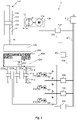
- FIG. 1 A preferred embodiment of an electro-hydrostatic actuator system 10 according to the invention is shown.
- the auxiliary pistons 200a, 200b, 200c and the pressing surface 120 of the upper piston 100 are only partially shown.
- the parts that are not shown are essentially symmetrical to the line of symmetry 50.
- the powder press drive shown has an upper piston 100 and a plurality of auxiliary pistons 200a, 200b, 200c. Since the auxiliary pistons shown are constructed essentially the same - with the exception of the pressing surfaces 220 -, auxiliary pistons and their sub-components are referred to below with the same reference numbers (e.g. 200a, 200b, 200c, 212, 216) Between the upper piston 100 and the auxiliary piston 200a, 200b, 200c 212, 216) a mold 400 is arranged, which contains a material to be pressed 410, e.g. powder.
- the upper piston 100 has a cylinder 110 with a first piston chamber 112 and a second piston chamber 114.
- the cylinder 110 is hydraulically acted upon by a first electro-hydrostatic actuator 130 with a pump 132 and a motor-generator 134.
- the pump volume-variable In the embodiment shown the pump volume-variable; however, a variable-speed motor-generator 134 may also be used, or a combination of both.
- the motor-generator 134 is connected via the upper piston control unit 140 to the electrical supply line 320 which—as shown here—may be implemented as a DC bus.
- the DC bus 320 is powered by the power supply 310
- the motor-generator 134 in motor function, acts on the first piston chamber 112.
- the piston 116 with the piston rod 118 is pressed downwards and thus actuates the pressing surface 120 of the upper piston 100, which on the one hand presses on the material to be pressed 410 in of the mold 400 and, on the other hand, displaces the pressing surfaces 220 of the auxiliary pistons 200a, 200b, 200c.
- the pressing surfaces 220 are connected to the piston rods 218 of the auxiliary pistons 200a, 200b, 200c.
- the piston 216 in the cylinder 210 of the auxiliary piston 200a, 200b, 200c thereby act on the second piston chambers 214 of the auxiliary piston 200a, 200b, 200c with pressure, so that the hydraulic fluid of the cylinder 210, the pump 232 of the second electro-hydrostatic actuators 230 actuated.
- the pumps 232 are connected to the motor generators 234 .
- These motor generators 234 are operated as generators in the press cycle.
- the motor generators 234 can thus feed current into the DC bus 320 via the control units 240, so that the current drawn by the motor generator 134 of the upper piston 100 from the power supply 310 in the pressing cycle is reduced.
- the pressing surfaces 220 of the auxiliary pistons 200a, 200b, 200c have a different thickness 222 in order to be optimally adapted to the areas of the powder blank to be produced.
- the pressing surfaces 220 can also be spaced apart from a base line by a rest distance or offset 224 in the starting position. This can at least partially replace the different thickness 222 and thus enables further flexibility when using the auxiliary pistons 200a, 200b, 200c.
- the press run (and also the rapid run) is controlled via the central control unit 350 .
- These contain the control characteristics for the upper piston 100 and the auxiliary pistons 200a, 200b, 200c and thus control the control devices 140 and 240 via the control bus 360.
- This control bus 360 can be implemented, for example, as a field bus or as a wireless connection.
- the motor generators 234 of the auxiliary pistons 200a, 200b, 200c are operated as a motor.
- the second piston chambers 214 of the auxiliary pistons are thus subjected to pressure, so that the pressing surfaces 220 of the auxiliary pistons 200a, 200b, 200c are pressed upwards.
- the motor generator 134 of the upper piston can be operated as a generator and current can be fed into the DC bus 320 via the control unit 140 .
Landscapes
- Engineering & Computer Science (AREA)
- Mechanical Engineering (AREA)
- Press Drives And Press Lines (AREA)
- Chemical & Material Sciences (AREA)
- Analytical Chemistry (AREA)
- Physics & Mathematics (AREA)
- Fluid Mechanics (AREA)
- General Engineering & Computer Science (AREA)
Claims (9)
- Système d'actionneurs électro-hydrostatiques (10) pour un entraînement de presse, comportantun piston supérieur (100) pourvu d'une surface de pressage (120), agissant depuis un premier sens, la surface de pressage (120) du piston supérieur (100) étant actionnée au moyen d'une tige de piston (118) dans un cylindre hydraulique (110) du piston supérieur (100) et parcourant un premier trajet dans une course de pressage,au moins un piston auxiliaire (200a, 200b, 200c) pourvu d'une surface de pressage (220), agissant depuis un second sens qui est opposé au premier sens, la surface de pressage (220) du piston auxiliaire (200a, 200b, 200c) étant actionnée au moyen d'une tige de piston (218) dans un cylindre hydraulique (210) du piston auxiliaire (100) et parcourant un second trajet dans la course de pressage,un premier actionneur électro-hydrostatique (130) pour l'entraînement du piston supérieur (100), pourvu d'une première pompe (132) et d'un premier moteur-générateur (134), qui est commandé par un premier appareil de commande (140),un second actionneur électro-hydrostatique (230) pour l'entraînement dudit au moins un piston auxiliaire (200a, 200b, 200c), pourvu d'une seconde pompe (232) et d'un second moteur-générateur (234), qui est commandé par un second appareil de commande (240) etpendant la course de pressage, le second moteur-générateur (234) du second actionneur électro-hydrostatique (230) étant exploité en tant que générateurcaractérisé en ce quele système (10) comporte une pluralité de pistons auxiliaires (200a, 200b, 200c) etau moins l'une des surfaces de pressage (220) des pistons auxiliaires (200a, 200b, 200c) présente une épaisseur différente (222) de celle d'une autre surface de pressage (220) et/ouau moins l'une des surfaces de pressage (220) présente une autre distance au repos (224) qu'une autre surface de pressage (220).
- Système d'actionneurs (10) selon la revendication 1, caractérisé en ce que
le second trajet de la seconde surface de pressage (220) est une fonction du premier trajet de la première surface de pressage (120) et le second trajet dans le premier sens est plus court que le premier trajet. - Système d'actionneurs (10) selon l'une quelconque des revendications précédentes, caractérisé en ce que
le système (10) comporte une pluralité de pistons supérieurs (100). - Système d'actionneurs (10) selon l'une quelconque des revendications précédentes, caractérisé en ce que
le ou les pistons supérieurs (100) sont conçus sous la forme d'actionneurs électro-hydrostatiques. - Système d'actionneurs (10) selon l'une quelconque des revendications précédentes, caractérisé en ce quele premier appareil de commande (140), qui est associé au premier moteur-générateur (134), comporte une première courbe caractéristique de commande etle second appareil de commande (240), qui est associé au second moteur-générateur (234), comporte une seconde courbe caractéristique de commande.
- Système d'actionneurs (10) selon la revendication 5, caractérisé en ce que
la première courbe caractéristique de commande et/ou la seconde courbe caractéristique de commande sont linéaires, polynomiales ou décrites par des points de courbe. - Système d'actionneurs (10) selon la revendication 5 ou 6, caractérisé en ce que
la première courbe caractéristique de commande et/ou la seconde courbe caractéristique de commande sont déterminées par une unité de commande centrale (350). - Système d'actionneurs (10) selon l'une quelconque des revendications précédentes, caractérisé en ce que
le système (10) comporte en outre une ligne d'alimentation électrique (320), à laquelle le premier appareil de commande (140) et le second appareil de commande (240) sont raccordés, de sorte que, dans la course de pressage, le second appareil de commande (240) alimente en courant la ligne d'alimentation (320). - Système d'actionneurs (10) selon l'une quelconque des revendications précédentes, caractérisé en ce que
le système (10) comporte en outre une avance rapide, le second moteur-générateur (234) du second actionneur électro-hydrostatique (230) étant exploité en tant que moteur.
Applications Claiming Priority (2)
| Application Number | Priority Date | Filing Date | Title |
|---|---|---|---|
| DE102018107245.7A DE102018107245A1 (de) | 2018-03-27 | 2018-03-27 | Pressenantrieb mit Energierückgewinnung |
| PCT/EP2019/056421 WO2019185362A1 (fr) | 2018-03-27 | 2019-03-14 | Entraînement de presse à récupération d'énergie |
Publications (2)
| Publication Number | Publication Date |
|---|---|
| EP3774316A1 EP3774316A1 (fr) | 2021-02-17 |
| EP3774316B1 true EP3774316B1 (fr) | 2022-04-27 |
Family
ID=65818001
Family Applications (1)
| Application Number | Title | Priority Date | Filing Date |
|---|---|---|---|
| EP19711877.1A Active EP3774316B1 (fr) | 2018-03-27 | 2019-03-14 | Entraînement de presse à récupération d'énergie |
Country Status (5)
| Country | Link |
|---|---|
| US (1) | US11498302B2 (fr) |
| EP (1) | EP3774316B1 (fr) |
| CN (1) | CN111902263B (fr) |
| DE (1) | DE102018107245A1 (fr) |
| WO (1) | WO2019185362A1 (fr) |
Cited By (1)
| Publication number | Priority date | Publication date | Assignee | Title |
|---|---|---|---|---|
| DE102024115017A1 (de) * | 2024-05-29 | 2025-12-04 | Moog Gmbh | Elektrohydrostatisches Antriebssystem und Verfahren zum Bewegen einer hydraulischen Achse |
Families Citing this family (1)
| Publication number | Priority date | Publication date | Assignee | Title |
|---|---|---|---|---|
| IT202100023789A1 (it) * | 2021-09-15 | 2023-03-15 | Util Ind S P A | Pressa multifunzione per la realizzazione di particolari metallici |
Family Cites Families (17)
| Publication number | Priority date | Publication date | Assignee | Title |
|---|---|---|---|---|
| ES2114044T3 (es) * | 1992-03-27 | 1998-05-16 | Mannesmann Rexroth Aktiengesel | Prensa con un accionamiento hidraulico, en particular una prensa de conformado de chapa. |
| US7000446B2 (en) * | 2004-03-05 | 2006-02-21 | Daimlerchrysler Corporation | Stamping press having four in one guide pin assembly |
| JP4576639B2 (ja) | 2005-05-16 | 2010-11-10 | アイダエンジニアリング株式会社 | プレス機械のダイクッション装置 |
| US8429946B2 (en) * | 2006-10-17 | 2013-04-30 | Honda Motor Co., Ltd. | Press-working method, and press-working apparatus |
| DE102008003106A1 (de) * | 2008-01-01 | 2009-07-02 | Dieffenbacher Gmbh + Co. Kg | Verfahren zum energiesparenden Betreiben einer hydraulischen Presse und eine energiesparende und wartungsarme hydraulische Presse |
| JP5428457B2 (ja) * | 2009-03-30 | 2014-02-26 | 三菱マテリアル株式会社 | 粉末成形装置 |
| DE102009049847A1 (de) * | 2009-10-19 | 2011-04-21 | Dorst Technologies Gmbh & Co. Kg | Metall- oder Keramikpulver-Presse und Steuerverfahren dafür |
| EP2593297A1 (fr) * | 2010-07-14 | 2013-05-22 | Demirer Teknolojik Sistemler Sanayi Ve Ticaret Limited Sirketi | Mode de réalisation permettant de réaliser des économies d'énergie dans des presses à plâtre |
| CN102363375A (zh) | 2011-06-30 | 2012-02-29 | 天津市天锻压力机有限公司 | 快速节能单动液压机 |
| CN102602020A (zh) * | 2012-03-29 | 2012-07-25 | 苏州市科林除尘设备有限公司 | 设置有多级往复增压器的缠绕式液压机 |
| DE102012104124A1 (de) * | 2012-05-10 | 2013-11-14 | Dieffenbacher GmbH Maschinen- und Anlagenbau | Verfahren und Vorrichtung zur adaptiven Steuerung einer hydraulischen Presse |
| EP2712688B1 (fr) * | 2012-09-28 | 2020-12-02 | Siemens Aktiengesellschaft | Entraînement de coussin hydraulique et procédé de fonctionnement d'un entraînement de coussin hydraulique |
| DE102013005876A1 (de) * | 2013-04-08 | 2014-10-09 | Robert Bosch Gmbh | Hydraulische Presse |
| DE102013109157B4 (de) * | 2013-08-23 | 2016-06-09 | Fette Compacting Gmbh | Presse zur Herstellung von Presslingen aus pulverförmigem Material |
| DE102014218887B3 (de) * | 2014-09-19 | 2016-01-28 | Voith Patent Gmbh | Hydraulischer Antrieb mit Eilhub und Lasthub |
| DE102017004803A1 (de) * | 2017-05-18 | 2018-11-22 | Cosateq Gmbh | Verfahren zum Betrieb einer Pulverpresse mit Lagenregelung und Pulverpresse zur Ausführung des Verfahrens |
| JP6670864B2 (ja) * | 2018-01-31 | 2020-03-25 | アイダエンジニアリング株式会社 | プレスシステム |
-
2018
- 2018-03-27 DE DE102018107245.7A patent/DE102018107245A1/de active Pending
-
2019
- 2019-03-14 US US17/042,292 patent/US11498302B2/en active Active
- 2019-03-14 CN CN201980022098.1A patent/CN111902263B/zh active Active
- 2019-03-14 EP EP19711877.1A patent/EP3774316B1/fr active Active
- 2019-03-14 WO PCT/EP2019/056421 patent/WO2019185362A1/fr not_active Ceased
Cited By (1)
| Publication number | Priority date | Publication date | Assignee | Title |
|---|---|---|---|---|
| DE102024115017A1 (de) * | 2024-05-29 | 2025-12-04 | Moog Gmbh | Elektrohydrostatisches Antriebssystem und Verfahren zum Bewegen einer hydraulischen Achse |
Also Published As
| Publication number | Publication date |
|---|---|
| CN111902263B (zh) | 2022-03-25 |
| US20210114325A1 (en) | 2021-04-22 |
| CN111902263A (zh) | 2020-11-06 |
| DE102018107245A1 (de) | 2019-10-02 |
| EP3774316A1 (fr) | 2021-02-17 |
| US11498302B2 (en) | 2022-11-15 |
| WO2019185362A1 (fr) | 2019-10-03 |
Similar Documents
| Publication | Publication Date | Title |
|---|---|---|
| EP1318906B1 (fr) | Dispositif de commande pour une presse hydraulique et procede pour son fonctionnement | |
| AT509239B1 (de) | Antriebsvorrichtung für eine biegepresse | |
| DE2921029A1 (de) | Pressen- und formhalteeinrichtung zum verdichten auf dem gebiet der pulvermetallurgie | |
| DE102014214739B3 (de) | Stanzvorrichtung, verfahren zum stanzen eines werkstücks und computerprogrammprodukt zur durchführung des verfahrens | |
| DE4308344A1 (de) | Verfahren zur Regelung des Antriebs einer hydraulischen Presse und Vorrichtung zur Durchführung des Verfahrens | |
| EP3880975B1 (fr) | Système d'actionneur électrohydrostatique | |
| DE10197111B4 (de) | Falzpresse | |
| DE102006015711B3 (de) | Stanzeinrichtung | |
| EP2846942B1 (fr) | Presse à filer hydraulique et procédé de fonctionnement d'une presse à filer hydraulique | |
| EP3115190B1 (fr) | Dispositif et procede de commande de l'entrainement principal d'une presse pour decoupage de precision | |
| EP3774316B1 (fr) | Entraînement de presse à récupération d'énergie | |
| EP1063028B2 (fr) | Presse pour hydroformage extérieur | |
| EP0629455A1 (fr) | Entraînement principal pour press à refouler | |
| EP2712688B1 (fr) | Entraînement de coussin hydraulique et procédé de fonctionnement d'un entraînement de coussin hydraulique | |
| DE19914840A1 (de) | Vorrichtung zum kontrollierten Antrieb | |
| DE102014101616B4 (de) | Hydraulisches Ziehkissen einer Ziehpresse und Verfahren zum Betreiben des hydraulischen Ziehkissens | |
| AT523856B1 (de) | Formgebungsmaschine mit einem geschlossenen, hydraulischen Antriebssystem | |
| DE2420726C3 (de) | Verfahren und Vorrichtung zur Herstellung von Preßkörpern mit schichtweise verschiedener Zusammensetzung für hochbelastbare elektrische Kontakte | |
| EP2114587B1 (fr) | Presse de formage présentant une fonction de coussin pneumatique intégrée au plateau coulissant | |
| DE19645627C5 (de) | Hydraulische Presse | |
| WO2011038921A1 (fr) | Procédé pour déplacer une unité de façonnage d'une machine | |
| DE102012102526A1 (de) | C-Gestell-Presse | |
| DE102007044259A1 (de) | Ziehwerkzeug mit kurzem Kraftweg | |
| DE202012001836U1 (de) | Antriebseinrichtung für eine Bearbeitungsmaschine | |
| DE102016110623A1 (de) | Hydraulische Pressmaschine mit Pulsatoren |
Legal Events
| Date | Code | Title | Description |
|---|---|---|---|
| STAA | Information on the status of an ep patent application or granted ep patent |
Free format text: STATUS: UNKNOWN |
|
| STAA | Information on the status of an ep patent application or granted ep patent |
Free format text: STATUS: THE INTERNATIONAL PUBLICATION HAS BEEN MADE |
|
| PUAI | Public reference made under article 153(3) epc to a published international application that has entered the european phase |
Free format text: ORIGINAL CODE: 0009012 |
|
| STAA | Information on the status of an ep patent application or granted ep patent |
Free format text: STATUS: REQUEST FOR EXAMINATION WAS MADE |
|
| 17P | Request for examination filed |
Effective date: 20201027 |
|
| AK | Designated contracting states |
Kind code of ref document: A1 Designated state(s): AL AT BE BG CH CY CZ DE DK EE ES FI FR GB GR HR HU IE IS IT LI LT LU LV MC MK MT NL NO PL PT RO RS SE SI SK SM TR |
|
| AX | Request for extension of the european patent |
Extension state: BA ME |
|
| DAV | Request for validation of the european patent (deleted) | ||
| DAX | Request for extension of the european patent (deleted) | ||
| GRAP | Despatch of communication of intention to grant a patent |
Free format text: ORIGINAL CODE: EPIDOSNIGR1 |
|
| STAA | Information on the status of an ep patent application or granted ep patent |
Free format text: STATUS: GRANT OF PATENT IS INTENDED |
|
| INTG | Intention to grant announced |
Effective date: 20211214 |
|
| GRAS | Grant fee paid |
Free format text: ORIGINAL CODE: EPIDOSNIGR3 |
|
| GRAA | (expected) grant |
Free format text: ORIGINAL CODE: 0009210 |
|
| STAA | Information on the status of an ep patent application or granted ep patent |
Free format text: STATUS: THE PATENT HAS BEEN GRANTED |
|
| AK | Designated contracting states |
Kind code of ref document: B1 Designated state(s): AL AT BE BG CH CY CZ DE DK EE ES FI FR GB GR HR HU IE IS IT LI LT LU LV MC MK MT NL NO PL PT RO RS SE SI SK SM TR |
|
| REG | Reference to a national code |
Ref country code: GB Ref legal event code: FG4D Free format text: NOT ENGLISH |
|
| REG | Reference to a national code |
Ref country code: CH Ref legal event code: EP |
|
| REG | Reference to a national code |
Ref country code: DE Ref legal event code: R096 Ref document number: 502019004201 Country of ref document: DE |
|
| REG | Reference to a national code |
Ref country code: AT Ref legal event code: REF Ref document number: 1486626 Country of ref document: AT Kind code of ref document: T Effective date: 20220515 |
|
| REG | Reference to a national code |
Ref country code: IE Ref legal event code: FG4D Free format text: LANGUAGE OF EP DOCUMENT: GERMAN |
|
| REG | Reference to a national code |
Ref country code: LT Ref legal event code: MG9D |
|
| REG | Reference to a national code |
Ref country code: NL Ref legal event code: MP Effective date: 20220427 |
|
| PG25 | Lapsed in a contracting state [announced via postgrant information from national office to epo] |
Ref country code: NL Free format text: LAPSE BECAUSE OF FAILURE TO SUBMIT A TRANSLATION OF THE DESCRIPTION OR TO PAY THE FEE WITHIN THE PRESCRIBED TIME-LIMIT Effective date: 20220427 |
|
| PG25 | Lapsed in a contracting state [announced via postgrant information from national office to epo] |
Ref country code: SE Free format text: LAPSE BECAUSE OF FAILURE TO SUBMIT A TRANSLATION OF THE DESCRIPTION OR TO PAY THE FEE WITHIN THE PRESCRIBED TIME-LIMIT Effective date: 20220427 Ref country code: PT Free format text: LAPSE BECAUSE OF FAILURE TO SUBMIT A TRANSLATION OF THE DESCRIPTION OR TO PAY THE FEE WITHIN THE PRESCRIBED TIME-LIMIT Effective date: 20220829 Ref country code: NO Free format text: LAPSE BECAUSE OF FAILURE TO SUBMIT A TRANSLATION OF THE DESCRIPTION OR TO PAY THE FEE WITHIN THE PRESCRIBED TIME-LIMIT Effective date: 20220727 Ref country code: LT Free format text: LAPSE BECAUSE OF FAILURE TO SUBMIT A TRANSLATION OF THE DESCRIPTION OR TO PAY THE FEE WITHIN THE PRESCRIBED TIME-LIMIT Effective date: 20220427 Ref country code: HR Free format text: LAPSE BECAUSE OF FAILURE TO SUBMIT A TRANSLATION OF THE DESCRIPTION OR TO PAY THE FEE WITHIN THE PRESCRIBED TIME-LIMIT Effective date: 20220427 Ref country code: GR Free format text: LAPSE BECAUSE OF FAILURE TO SUBMIT A TRANSLATION OF THE DESCRIPTION OR TO PAY THE FEE WITHIN THE PRESCRIBED TIME-LIMIT Effective date: 20220728 Ref country code: FI Free format text: LAPSE BECAUSE OF FAILURE TO SUBMIT A TRANSLATION OF THE DESCRIPTION OR TO PAY THE FEE WITHIN THE PRESCRIBED TIME-LIMIT Effective date: 20220427 Ref country code: BG Free format text: LAPSE BECAUSE OF FAILURE TO SUBMIT A TRANSLATION OF THE DESCRIPTION OR TO PAY THE FEE WITHIN THE PRESCRIBED TIME-LIMIT Effective date: 20220727 |
|
| PG25 | Lapsed in a contracting state [announced via postgrant information from national office to epo] |
Ref country code: RS Free format text: LAPSE BECAUSE OF FAILURE TO SUBMIT A TRANSLATION OF THE DESCRIPTION OR TO PAY THE FEE WITHIN THE PRESCRIBED TIME-LIMIT Effective date: 20220427 Ref country code: PL Free format text: LAPSE BECAUSE OF FAILURE TO SUBMIT A TRANSLATION OF THE DESCRIPTION OR TO PAY THE FEE WITHIN THE PRESCRIBED TIME-LIMIT Effective date: 20220427 Ref country code: LV Free format text: LAPSE BECAUSE OF FAILURE TO SUBMIT A TRANSLATION OF THE DESCRIPTION OR TO PAY THE FEE WITHIN THE PRESCRIBED TIME-LIMIT Effective date: 20220427 Ref country code: IS Free format text: LAPSE BECAUSE OF FAILURE TO SUBMIT A TRANSLATION OF THE DESCRIPTION OR TO PAY THE FEE WITHIN THE PRESCRIBED TIME-LIMIT Effective date: 20220827 |
|
| REG | Reference to a national code |
Ref country code: DE Ref legal event code: R097 Ref document number: 502019004201 Country of ref document: DE |
|
| PG25 | Lapsed in a contracting state [announced via postgrant information from national office to epo] |
Ref country code: SM Free format text: LAPSE BECAUSE OF FAILURE TO SUBMIT A TRANSLATION OF THE DESCRIPTION OR TO PAY THE FEE WITHIN THE PRESCRIBED TIME-LIMIT Effective date: 20220427 Ref country code: SK Free format text: LAPSE BECAUSE OF FAILURE TO SUBMIT A TRANSLATION OF THE DESCRIPTION OR TO PAY THE FEE WITHIN THE PRESCRIBED TIME-LIMIT Effective date: 20220427 Ref country code: RO Free format text: LAPSE BECAUSE OF FAILURE TO SUBMIT A TRANSLATION OF THE DESCRIPTION OR TO PAY THE FEE WITHIN THE PRESCRIBED TIME-LIMIT Effective date: 20220427 Ref country code: ES Free format text: LAPSE BECAUSE OF FAILURE TO SUBMIT A TRANSLATION OF THE DESCRIPTION OR TO PAY THE FEE WITHIN THE PRESCRIBED TIME-LIMIT Effective date: 20220427 Ref country code: EE Free format text: LAPSE BECAUSE OF FAILURE TO SUBMIT A TRANSLATION OF THE DESCRIPTION OR TO PAY THE FEE WITHIN THE PRESCRIBED TIME-LIMIT Effective date: 20220427 Ref country code: DK Free format text: LAPSE BECAUSE OF FAILURE TO SUBMIT A TRANSLATION OF THE DESCRIPTION OR TO PAY THE FEE WITHIN THE PRESCRIBED TIME-LIMIT Effective date: 20220427 Ref country code: CZ Free format text: LAPSE BECAUSE OF FAILURE TO SUBMIT A TRANSLATION OF THE DESCRIPTION OR TO PAY THE FEE WITHIN THE PRESCRIBED TIME-LIMIT Effective date: 20220427 |
|
| PLBE | No opposition filed within time limit |
Free format text: ORIGINAL CODE: 0009261 |
|
| STAA | Information on the status of an ep patent application or granted ep patent |
Free format text: STATUS: NO OPPOSITION FILED WITHIN TIME LIMIT |
|
| PG25 | Lapsed in a contracting state [announced via postgrant information from national office to epo] |
Ref country code: AL Free format text: LAPSE BECAUSE OF FAILURE TO SUBMIT A TRANSLATION OF THE DESCRIPTION OR TO PAY THE FEE WITHIN THE PRESCRIBED TIME-LIMIT Effective date: 20220427 |
|
| 26N | No opposition filed |
Effective date: 20230130 |
|
| PG25 | Lapsed in a contracting state [announced via postgrant information from national office to epo] |
Ref country code: SI Free format text: LAPSE BECAUSE OF FAILURE TO SUBMIT A TRANSLATION OF THE DESCRIPTION OR TO PAY THE FEE WITHIN THE PRESCRIBED TIME-LIMIT Effective date: 20220427 |
|
| PG25 | Lapsed in a contracting state [announced via postgrant information from national office to epo] |
Ref country code: MC Free format text: LAPSE BECAUSE OF FAILURE TO SUBMIT A TRANSLATION OF THE DESCRIPTION OR TO PAY THE FEE WITHIN THE PRESCRIBED TIME-LIMIT Effective date: 20220427 |
|
| REG | Reference to a national code |
Ref country code: CH Ref legal event code: PL |
|
| GBPC | Gb: european patent ceased through non-payment of renewal fee |
Effective date: 20230314 |
|
| REG | Reference to a national code |
Ref country code: BE Ref legal event code: MM Effective date: 20230331 |
|
| PG25 | Lapsed in a contracting state [announced via postgrant information from national office to epo] |
Ref country code: LU Free format text: LAPSE BECAUSE OF NON-PAYMENT OF DUE FEES Effective date: 20230314 |
|
| REG | Reference to a national code |
Ref country code: IE Ref legal event code: MM4A |
|
| PG25 | Lapsed in a contracting state [announced via postgrant information from national office to epo] |
Ref country code: GB Free format text: LAPSE BECAUSE OF NON-PAYMENT OF DUE FEES Effective date: 20230314 |
|
| PG25 | Lapsed in a contracting state [announced via postgrant information from national office to epo] |
Ref country code: LI Free format text: LAPSE BECAUSE OF NON-PAYMENT OF DUE FEES Effective date: 20230331 Ref country code: IT Free format text: LAPSE BECAUSE OF FAILURE TO SUBMIT A TRANSLATION OF THE DESCRIPTION OR TO PAY THE FEE WITHIN THE PRESCRIBED TIME-LIMIT Effective date: 20220427 Ref country code: IE Free format text: LAPSE BECAUSE OF NON-PAYMENT OF DUE FEES Effective date: 20230314 Ref country code: GB Free format text: LAPSE BECAUSE OF NON-PAYMENT OF DUE FEES Effective date: 20230314 Ref country code: FR Free format text: LAPSE BECAUSE OF NON-PAYMENT OF DUE FEES Effective date: 20230331 Ref country code: CH Free format text: LAPSE BECAUSE OF NON-PAYMENT OF DUE FEES Effective date: 20230331 |
|
| PG25 | Lapsed in a contracting state [announced via postgrant information from national office to epo] |
Ref country code: BE Free format text: LAPSE BECAUSE OF NON-PAYMENT OF DUE FEES Effective date: 20230331 |
|
| PG25 | Lapsed in a contracting state [announced via postgrant information from national office to epo] |
Ref country code: BG Free format text: LAPSE BECAUSE OF FAILURE TO SUBMIT A TRANSLATION OF THE DESCRIPTION OR TO PAY THE FEE WITHIN THE PRESCRIBED TIME-LIMIT Effective date: 20220427 |
|
| PG25 | Lapsed in a contracting state [announced via postgrant information from national office to epo] |
Ref country code: BG Free format text: LAPSE BECAUSE OF FAILURE TO SUBMIT A TRANSLATION OF THE DESCRIPTION OR TO PAY THE FEE WITHIN THE PRESCRIBED TIME-LIMIT Effective date: 20220427 |
|
| REG | Reference to a national code |
Ref country code: AT Ref legal event code: MM01 Ref document number: 1486626 Country of ref document: AT Kind code of ref document: T Effective date: 20240314 |
|
| PG25 | Lapsed in a contracting state [announced via postgrant information from national office to epo] |
Ref country code: AT Free format text: LAPSE BECAUSE OF NON-PAYMENT OF DUE FEES Effective date: 20240314 |
|
| PG25 | Lapsed in a contracting state [announced via postgrant information from national office to epo] |
Ref country code: CY Free format text: LAPSE BECAUSE OF FAILURE TO SUBMIT A TRANSLATION OF THE DESCRIPTION OR TO PAY THE FEE WITHIN THE PRESCRIBED TIME-LIMIT; INVALID AB INITIO Effective date: 20190314 |
|
| PG25 | Lapsed in a contracting state [announced via postgrant information from national office to epo] |
Ref country code: HU Free format text: LAPSE BECAUSE OF FAILURE TO SUBMIT A TRANSLATION OF THE DESCRIPTION OR TO PAY THE FEE WITHIN THE PRESCRIBED TIME-LIMIT; INVALID AB INITIO Effective date: 20190314 |
|
| PG25 | Lapsed in a contracting state [announced via postgrant information from national office to epo] |
Ref country code: TR Free format text: LAPSE BECAUSE OF FAILURE TO SUBMIT A TRANSLATION OF THE DESCRIPTION OR TO PAY THE FEE WITHIN THE PRESCRIBED TIME-LIMIT Effective date: 20220427 |
|
| PGFP | Annual fee paid to national office [announced via postgrant information from national office to epo] |
Ref country code: DE Payment date: 20260319 Year of fee payment: 8 |
|
| PGFP | Annual fee paid to national office [announced via postgrant information from national office to epo] |
Ref country code: AT Payment date: 20260410 Year of fee payment: 5 |