EP3774502B1 - Fahrzeug mit einer batterieschutzvorrichtung zum eingriff mit der felge eines rades - Google Patents
Fahrzeug mit einer batterieschutzvorrichtung zum eingriff mit der felge eines rades Download PDFInfo
- Publication number
- EP3774502B1 EP3774502B1 EP19715159.0A EP19715159A EP3774502B1 EP 3774502 B1 EP3774502 B1 EP 3774502B1 EP 19715159 A EP19715159 A EP 19715159A EP 3774502 B1 EP3774502 B1 EP 3774502B1
- Authority
- EP
- European Patent Office
- Prior art keywords
- vehicle
- rim
- structural element
- wheel
- block
- Prior art date
- Legal status (The legal status is an assumption and is not a legal conclusion. Google has not performed a legal analysis and makes no representation as to the accuracy of the status listed.)
- Active
Links
Images
Classifications
-
- B—PERFORMING OPERATIONS; TRANSPORTING
- B62—LAND VEHICLES FOR TRAVELLING OTHERWISE THAN ON RAILS
- B62D—MOTOR VEHICLES; TRAILERS
- B62D21/00—Understructures, i.e. chassis frame on which a vehicle body may be mounted
- B62D21/15—Understructures, i.e. chassis frame on which a vehicle body may be mounted having impact absorbing means, e.g. a frame designed to permanently or temporarily change shape or dimension upon impact with another body
- B62D21/157—Understructures, i.e. chassis frame on which a vehicle body may be mounted having impact absorbing means, e.g. a frame designed to permanently or temporarily change shape or dimension upon impact with another body for side impacts
-
- B—PERFORMING OPERATIONS; TRANSPORTING
- B62—LAND VEHICLES FOR TRAVELLING OTHERWISE THAN ON RAILS
- B62D—MOTOR VEHICLES; TRAILERS
- B62D21/00—Understructures, i.e. chassis frame on which a vehicle body may be mounted
- B62D21/11—Understructures, i.e. chassis frame on which a vehicle body may be mounted with resilient means for suspension, e.g. of wheels or engine; sub-frames for mounting engine or suspensions
Definitions
- the present invention relates to the field of passive safety equipment for a vehicle. It is more particularly in the field of protection against side impacts of motor vehicles of the hybrid or electric type.
- Motor vehicles of the electric type comprise only an electric motor.
- Motor vehicles of the hybrid type comprise a heat engine in addition to an electric motor.
- the two motors operate simultaneously or alternately so as to reduce the total power consumed by the vehicle.
- the propulsion battery of the electric motor is generally parallelepipedic in shape, and is housed in the rear part of the vehicle, in the boot or under the body.
- the propulsion battery supplying the electric motor extends at least partially under the rear passenger seats, between the locations of the rear wheels, and in the transverse direction of the vehicle.
- WO2014/015094A2 is considered to be the state of the art closest to the subject-matter of claim 1.
- WO2014/015094A2 discloses a motor vehicle comprising at least one wheel having a rim placed facing a vehicle structural element in the transverse direction of said vehicle, the vehicle of which further comprises at least one bracing device ("extendable member 524, pin 530 and cylinder 520") arranged between said rim and said structural element ( Figure 11).
- the object of the invention is to provide a solution to the problems encountered in the prior art by proposing a new vehicle offering protection of the elements placed between the two wheels of the same train against the displacement of one of said wheels in the direction of the median axis of the vehicle during a collision of the pole impact type at the level of said wheel.
- the subject of the invention is a motor vehicle comprising at least one wheel having a rim placed facing a vehicle structural element in the transverse direction of said vehicle, the vehicle being remarkable in that that it further comprises at least one spacer device arranged between said rim and said structural element.
- the vehicle further comprises a shock absorber, a lower spring cup of which is arranged opposite an element to be protected, the spacing between at least one spacer device and the wheel rim being less than or equal to the spacing between the lower cup and the element to be protected, the bracing device being in the form of a block fixed to said structural element.
- the bracing device has a protective role in the event of a side impact of the pole type centered on one of the wheels of the vehicle which drives deformation of the undercarriage and damage to the elements located close to the wheel, either directly or indirectly by displacement of elements fixed to said undercarriage.
- the positioning of the bracing device between the rim and a structural element allows faster locking of the wheel in the Y direction of the vehicle during the impact kinematics. It also makes it possible to limit the sinking of the wheel.
- the bracing device acts as a “wedge” between the rim and the adjacent body structure elements.
- Such a configuration is very advantageous in that the device is very easy to mount during the design of the vehicle, preferably right at the end of production.
- the vehicle comprises a pair of rear wheels, and is remarkable in that at least one bracing device is arranged between the rim of a rear wheel and the beam corresponding to the structural element positioned opposite said rim.
- the vehicle is of the hybrid or electric type and comprises a battery arranged to be disposed at least partly between the rear wheels.
- the rear axle may deform, thus causing the displacement of other elements fixed to it, said items that may collide with the battery.
- the spacer device is therefore a battery protection device.
- the bracing device can be a device for protecting a fuel tank.
- At least one bracing device forms part of the structural element or is fixed to said structural element.
- at least one bracing device is integral with the mudguard or is fixed to the mudguard.
- Several bracing devices can be combined to form a set showing the desired thickness.
- At least one spacer device is in the form of a block fixed to said structural element.
- the fixing takes place by screwing, by scratching, by clipping or by gluing.
- the vehicle being equipped with at least one mudguard, said mudguard comprising a body, one side wall of which is arranged facing the structural element and has an internal face and an external face
- at least one bracing device is a block fixed to or integral with the side wall of the mudguard and is arranged to extend from its internal face and/or its external face .
- the bracing device is in the form of a block consisting of a solid body or a partitioned block comprising a network of internal partitions formed by a network of ribs oriented to extend along the transverse direction of the vehicle.
- the spacer device is made of a composite material comprising a thermoplastic matrix filled with fibers.
- a spacer device is formed by a relief on the face of the structural element arranged facing the rim, said relief extending towards said rim in the transverse direction of said vehicle.
- the relief is obtained by stamping or by molding.
- the spacer device is fixed to the structural element and is in the form of a section forming a hollow body with said structural element.
- the spacer device is advantageously made of metal, for example steel or aluminum.
- a block of polyurethane foam is inserted inside said hollow body.
- the spacer device is made of metal.
- an example of combination can be the use of a spacer device formed by hollow body according to the fourth embodiment with a spacer device fixed on the mudguard according to the second embodiment.
- Another example of a combination comprises two bracing devices according to the first and second embodiments overlapping at least partially in the transverse direction of the vehicle.
- the person skilled in the art can combine the first and the third embodiment, or even the first, second and third embodiments.
- the vehicle further comprising a shock absorber, a lower spring cup of which is arranged opposite an element to be protected
- the vehicle is remarkable in that the spacing between at least one device of bracing and the wheel rim is less than or equal to the spacing between the lower cup and the element to be protected.
- the element to be protected is a battery. Thanks to this difference in play between said parts of the vehicle, the wheel is blocked during a side impact of the pole type without the sealing of the element to be protected, such as a fuel tank or a battery, being damaged. indirectly, i.e. via the lower spring retainer of a shock absorber.
- the term “comprise” is synonymous with “include” and is not limiting in that it authorizes the presence of other elements in the vehicle to which it relates. It is understood that the term “include” includes the terms “consist of”. The terms “lower”, “upper”, “front” and “rear” will be understood in relation to the general orientation of the vehicle. “Lower” will designate a greater proximity to the ground than “upper” along the vertical axis. In the various figures, the same references designate identical or similar elements.
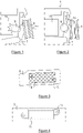
- the figure 1 having been commented on in the introductory part, reference will now be made to the picture 2 showing a motor vehicle 1 according to the invention.
- the vehicle 1 comprises at least one wheel having a rim 5 placed opposite a structural element 3 of the vehicle in the transverse direction of said vehicle.
- the vehicle 1 is remarkable in that it further comprises at least one spacer device 13 arranged between said rim 5 and said structural element 3.
- the vehicle comprises a pair of rear wheels (only one of said wheels is shown), and at least one bracing device 13 is arranged between the rim 5 of a rear wheel and the corresponding beam 3 to the structural element positioned opposite said rim 5.
- the structural element can be a front stretcher.
- the bracing device is then associated with a front wheel of the vehicle.
- a vehicle according to the invention may have bracing devices either at the level of the front wheels or at the level of the rear wheels or at the level of both the front wheels and the rear wheels.
- the vehicle according to the invention can have any type of engine, thermal, hybrid or electric. Nevertheless, the invention will have a particular advantage for vehicles of the hybrid or electric type comprising a battery arranged to be disposed at least in part between the rear wheels.
- the bracing device 13 then forms a passive protection device for the propulsion battery 11 .
- a bracing device 13 is fixed to the structural element 3 of the vehicle 1 (here, a side member). Nevertheless, in other embodiments of the invention, it is possible for at least one bracing device to form part of the structural element. Alternatively or additionally, at least one spacer device is integral with the mudguard or is attached thereto. Several bracing devices can be combined to form an assembly showing a given thickness. For example, it is possible to envisage associating a relief shown by the structural element and a spacer device made in one piece on the mudguard facing said element.
- the figures 3 and 4 illustrate a first embodiment of the invention in which the spacer device 13 is in the form of a block fixed to said structural element 3.
- the fixing can be done by any means.
- the fixing takes place by screwing, by scratching, by clipping or by gluing.
- the fixing can be done by magnetization. A person skilled in the art will easily find a method of attaching said device to said structural element.
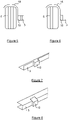
- the bracing device 13 is in the form of a partitioned block comprising a network of internal partitions formed by a network of ribs oriented to extend in the transverse direction of the vehicle.
- the internal structure is honeycomb.
- the fixing of such a device can be carried out using claws mechanical 15.
- a device is fixed to said structural element 3 by at least two claws 15.
- the bracing device 13 is in the form of a solid block and is fixed by screwing.
- the screw-nut system is placed on at least one fixing lug 17 extending from one of the sides of the bracing device 13 and resting against one of the faces of the structural element 3.
- bracing device in the form of a partitioned block and provided with fixing lugs 17 for fixing by screwing.
- the bracing device 13 is intended to be placed in a zone previously empty of material in order to allow the wheel to lock more quickly against the structural element facing the rim in the event of a lateral collision of the post type.
- the bracing device(s) must have a certain resistance and not crush under the force resulting from the impact.
- the spacer devices 13 according to the invention can be made of thermoplastic or thermosetting composite material.
- a preferred implementation of the invention will favor the use of thermoplastic matrices which have higher delamination and breakage limits than thermosetting resins.
- the thermoplastic polymer matrix will advantageously be selected from one or more materials chosen from polypropylene (PP), polyphthalamide (PPA), polyetheretherketone (PEEK), polyphenylene sulphide (PPS), polyamide-imide (PAI), polyetherimide ( PEI), polyarylamide (PAA), or polyamide (PA) such as, for example, polyamide 6 (PA 6 or polycaprolactam) or polyamide 6.6 (PA 6.6 or polyhexamethylene adipamide).
- the matrix used can be reinforced with fibers, for example glass fibers or carbon fibers.
- the spacer devices 13 can be made of metal, for example steel or aluminum.
- the bracing device 13 can be made of metal or of a composite material.
- it is advantageously formed from a composite material so as not to weigh down the vehicle too much.
- the vehicle being provided with at least one mudguard 19, said mudguard 19 comprises a body, one side wall of which is arranged facing the structural element 3 and which has an internal face and an external face.
- a mud flap is a device, generally made of thermoplastic material, which separates the interior of the structure of a vehicle from the exterior space, and which is intended to get a wheel.
- One of the functions of a mud flap is, as its name suggests, to prevent mud that sticks against the wheel of a vehicle from being projected onto the internal metal structure of the vehicle. Mud flaps also perform a noise attenuation function and contribute to the sound insulation of the vehicle interior.
- the terms “internal” and “external” will be understood in relation to the general curvature of the mudguard.
- the inner surface of the wall of the mudguard is arranged facing the wheel.
- At least one bracing device 13 is a block fixed to or integral with the side wall of the mudguard 19 and arranged to extend from its internal face and/or from its external face. Indeed, in particular when the spacer device 13 is integral with the side wall, it can be through, that is to say it extends on either side of the side wall of the mud guard device.
- the bracing device 13 is fixed to the outer face of the side wall of the mudguard 19.
- the bracing device 13 is fixed to the internal face of the side wall of the mudguard 19.
- the bracing device 13, when it is fixed or integral with a mudguard 19, can be in the form of a solid block or a partitioned block comprising a network of internal partitions participating to the stiffness of the part. It may be made of metal or of a composite material, the composite material possibly being as described above. When attached to the fender, it is attached by any means.
- the spacer device(s) 13 according to the invention are made of thermoplastic material and are integral with the mudguard 19. The person skilled in the art will easily produce such a guard. -mud having a bracing device on at least one of its faces forming a bulge, for example by molding or by co-moulding.
- a bracing device 13 is formed by a relief on the face of the structural element 3 arranged facing the rim (not shown), said relief extending towards said rim in the transverse direction of said vehicle, therefore s extending perpendicular to the face on which it is formed.
- said relief is obtained by stamping or by molding.
- the bracing device 13 is fixed to the structural element 3 and is in the form of a profile forming a hollow body with said structural element 3.
- the fixing is carried out by gluing, by welding or by screwing.
- the fixing is carried out by welding during the step of fitting the vehicle.
- the bracing device is advantageously made of metal, for example steel or aluminum in order to show sufficient strength.
- the rigidity of the assembly is optionally supplemented by the insertion of a block of polyurethane foam, inside said hollow body.
- the foam is advantageously chosen to be dense and therefore has a density of at least 80 g/l for this purpose.
- the vehicle further comprising a shock absorber of which a lower spring cup 9 is arranged facing an element to be protected 11 (here a battery)
- the vehicle is remarkable in that that the spacing between at least one bracing device 13 and the wheel rim 5 is less than or equal to the spacing between the lower cup 9 and the element to be protected 11. Thanks to this difference in clearance between said parts of the vehicle, the wheel is blocked during a side impact of the pole type without the sealing of the element to be protected 11, such as a fuel tank or a battery, being damaged indirectly by the lower cup 9 of spring from a shock absorber.
Landscapes
- Engineering & Computer Science (AREA)
- Chemical & Material Sciences (AREA)
- Combustion & Propulsion (AREA)
- Transportation (AREA)
- Mechanical Engineering (AREA)
- Body Structure For Vehicles (AREA)
- Arrangement Or Mounting Of Propulsion Units For Vehicles (AREA)
Claims (5)
- Kraftfahrzeug (1) mit mindestens einem Rad, das eine Felge (5) aufweist, die einem Fahrzeugstrukturelement (3) in Querrichtung des Fahrzeugs zugewandt ist, wobei mindestens eine Abstandeinrichtung (13) zwischen der Felge (5) und dem Strukturelement (3) angeordnet ist, wobei das Fahrzeug (1) ferner einen Dämpfer aufweist, dessen untere Federkappe (9) angeordnet ist Gegenüber einem zu schützenden Element (11) ist der Abstand zwischen mindestens einer Abstandvorrichtung (13) und der Radfelge (5) kleiner oder gleich dem Abstand zwischen der unteren Schale (9) und dem zu schützenden Element (11), wobei die Abstandvorrichtung (13) als Block ausgebildet ist, der an dem Strukturelement (3) befestigt ist.
- Fahrzeug (1) nach Anspruch 1, das ein Paar Hinterräder umfasst, wobei das Fahrzeug (1) dadurch gekennzeichnet ist, dass mindestens eine Abstandeinrichtung (13) zwischen der Felge (5) eines Hinterrades und dem Längsträger (3) angeordnet ist, der dem der Felge (5) zugewandten Strukturelement entspricht, wobei das Fahrzeug (1) vom hybriden oder elektrischen Typ ist und eine Batterie aufweist 11) so angeordnet ist, dass sie zumindest teilweise zwischen den Hinterrädern angeordnet ist.
- Fahrzeug (1) nach einem der Ansprüche 1 bis 2, wobei das Fahrzeug (1) mit mindestens einer Blende (19) versehen ist, wobei die Blende (19) einen Körper umfasst, dessen Seitenwand gegenüber dem Strukturelement (3) angeordnet ist und eine Innenseite und eine Außenseite aufweist, wobei das Fahrzeug (1) dadurch gekennzeichnet ist, dass mindestens eine Abstandvorrichtung (13) vorgesehen ist ist ein Block, der mit dem Seitenteil der Kotscheibe (19) an oder aus Material befestigt ist und von seiner Innenseite und/oder von seiner Außenseite aus sich erstreckt.
- Fahrzeug (1) nach einem der Ansprüche 1 bis 3, dadurch gekennzeichnet, dass mindestens eine Abstandeinrichtung (13)- in Form eines Blocks aus einem Vollkörper oder einem Klotzblock mit einer Anordnung von inneren Trennwänden, die durch ein Gitter von Rippen gebildet sind, die in Querrichtung des Fahrzeugs (1) ausgerichtet sind, und/oder- aus einem Verbundwerkstoff hergestellt ist, der eine fasergefüllte thermoplastische Matrix umfasst.
- Fahrzeug (1) nach einem der Ansprüche 1 oder 2, dadurch gekennzeichnet, dass die Abstandeinrichtung (13)- an dem Strukturelement (3) befestigt ist und als Hohlkörper-Profil mit dem Strukturelement (3) ausgebildet ist, vorzugsweise ein Polyurethan-Schaumblock in den Hohlkörper eingesetzt ist; oder- durch eine Erhebung auf der der Felge (5) zugewandten Seite des Strukturelements (3) gebildet ist, wobei sich die Erhebung in Querrichtung des Fahrzeugs (1) zu der Felge (5) erstreckt, vorzugsweise durch Tiefziehen oder Formen.
Applications Claiming Priority (2)
| Application Number | Priority Date | Filing Date | Title |
|---|---|---|---|
| FR1853094A FR3079794B1 (fr) | 2018-04-10 | 2018-04-10 | Vehicule comprenant dispositif de protection de batterie destine a cooperer avec la jante d’une roue |
| PCT/FR2019/050504 WO2019197736A1 (fr) | 2018-04-10 | 2019-03-06 | Véhicule comprenant un dispositif de protection de batterie destine a cooperer avec la jante d'une roue |
Publications (2)
| Publication Number | Publication Date |
|---|---|
| EP3774502A1 EP3774502A1 (de) | 2021-02-17 |
| EP3774502B1 true EP3774502B1 (de) | 2022-11-16 |
Family
ID=62167590
Family Applications (1)
| Application Number | Title | Priority Date | Filing Date |
|---|---|---|---|
| EP19715159.0A Active EP3774502B1 (de) | 2018-04-10 | 2019-03-06 | Fahrzeug mit einer batterieschutzvorrichtung zum eingriff mit der felge eines rades |
Country Status (4)
| Country | Link |
|---|---|
| EP (1) | EP3774502B1 (de) |
| CN (1) | CN111954617A (de) |
| FR (1) | FR3079794B1 (de) |
| WO (1) | WO2019197736A1 (de) |
Families Citing this family (1)
| Publication number | Priority date | Publication date | Assignee | Title |
|---|---|---|---|---|
| FR3111319B1 (fr) * | 2020-06-15 | 2023-07-14 | Psa Automobiles Sa | Vehicule automobile equipe d’une cale résistante de protection d’une batterie de traction |
Citations (2)
| Publication number | Priority date | Publication date | Assignee | Title |
|---|---|---|---|---|
| WO2014015094A2 (en) * | 2012-07-20 | 2014-01-23 | Key Safety Systems Inc. | Offset impact countermeasures |
| US20150101877A1 (en) * | 2013-10-15 | 2015-04-16 | Toyota Jidosha Kabushiki Kaisha | Vehicle front structure |
Family Cites Families (11)
| Publication number | Priority date | Publication date | Assignee | Title |
|---|---|---|---|---|
| JP2797791B2 (ja) * | 1991-10-29 | 1998-09-17 | トヨタ自動車株式会社 | 自動車車体の前部構造 |
| JP5288000B2 (ja) * | 2010-03-02 | 2013-09-11 | トヨタ自動車株式会社 | 車両前部構造 |
| DE102011002650B4 (de) * | 2011-01-13 | 2023-12-07 | Ford Global Technologies, Llc | Kraftfahrzeug |
| SE1300131A1 (sv) * | 2013-02-19 | 2014-08-20 | Elaion Ab | Expanderbar struktur för positionering av hjul och förbättring av ett fordons kollisionsskydd |
| DE102013217113B3 (de) * | 2013-08-28 | 2015-03-19 | Ford Global Technologies, Llc | Blattfederlager sowie Fahrzeugradaufhängung für ein Fahrzeug mit Querblattfeder |
| US9403556B2 (en) * | 2014-03-04 | 2016-08-02 | Ford Global Technologies, Llc | Wheel assembly kinematic enhancement device |
| US9120507B1 (en) * | 2014-05-27 | 2015-09-01 | Ford Global Technologies, Llc | System for orienting front wheel of vehicle during offset frontal impact |
| US8985258B1 (en) * | 2014-05-30 | 2015-03-24 | Ford Global Technologies, Llc | Vehicle frame component |
| US9926012B2 (en) * | 2016-01-27 | 2018-03-27 | Ford Global Technologies, Llc | Vehicle frame including bracket for small offset rigid barrier test |
| CN205801256U (zh) * | 2016-07-28 | 2016-12-14 | 长城汽车股份有限公司 | 车辆侧围门槛梁和车身框架及车辆 |
| US10065586B2 (en) * | 2016-11-22 | 2018-09-04 | Ford Global Technologies, Llc | Deployable device mounted to vehicle frame |
-
2018
- 2018-04-10 FR FR1853094A patent/FR3079794B1/fr not_active Expired - Fee Related
-
2019
- 2019-03-06 WO PCT/FR2019/050504 patent/WO2019197736A1/fr not_active Ceased
- 2019-03-06 CN CN201980024181.2A patent/CN111954617A/zh active Pending
- 2019-03-06 EP EP19715159.0A patent/EP3774502B1/de active Active
Patent Citations (2)
| Publication number | Priority date | Publication date | Assignee | Title |
|---|---|---|---|---|
| WO2014015094A2 (en) * | 2012-07-20 | 2014-01-23 | Key Safety Systems Inc. | Offset impact countermeasures |
| US20150101877A1 (en) * | 2013-10-15 | 2015-04-16 | Toyota Jidosha Kabushiki Kaisha | Vehicle front structure |
Also Published As
| Publication number | Publication date |
|---|---|
| EP3774502A1 (de) | 2021-02-17 |
| WO2019197736A1 (fr) | 2019-10-17 |
| FR3079794A1 (fr) | 2019-10-11 |
| CN111954617A (zh) | 2020-11-17 |
| FR3079794B1 (fr) | 2020-10-23 |
Similar Documents
| Publication | Publication Date | Title |
|---|---|---|
| WO2019162583A1 (fr) | Dispositif de protection de batterie en cas de choc lateral et vehicule equipe d'un tel dispositif | |
| EP1277622B1 (de) | Kraftfahrzeugstossfänger | |
| WO2005100100A1 (fr) | Lot d'au moins deux appuis bas pour pare-choc de vehicule automobile, et lot de deux blocs avant | |
| WO2020260482A1 (fr) | Batterie de stockage d'électricité et véhicule | |
| EP3661812B1 (de) | Stossdämpferanordnung für kraftfahrzeug | |
| FR3063458A1 (fr) | Dispositif de protection lateral de la batterie de propulsion d’un vehicule hybride ou electrique | |
| EP4021781B1 (de) | Hybrid- oder elektrofahrzeug mit vorrichtung zur verstärkung seiner schwellerstruktur | |
| EP3774502B1 (de) | Fahrzeug mit einer batterieschutzvorrichtung zum eingriff mit der felge eines rades | |
| WO2023203288A1 (fr) | Véhicule automobile comprenant un longeron avec une pièce de renfort | |
| WO2022171943A1 (fr) | Véhicules à motorisation électrique hybride pourvus d'un dispositif de renfort relié au brancard avant | |
| EP4323260A1 (de) | Hybridfahrzeuge | |
| EP4267419A1 (de) | Unterbodenstruktur für ein kraftfahrzeug | |
| EP3877238B1 (de) | Vorrichtung zum schutz einer stromversorgungsbatterie eines kraftfahrzeugs | |
| FR3082788A1 (fr) | Vehicule avec dispositif de protection de batterie sous-plancher et dispositif de protection | |
| FR3058365A1 (fr) | Support pour batterie multifonction | |
| FR3066966B1 (fr) | Dispositif d’entretoisement pour appui de roue de vehicule en choc arriere et vehicule presentant un tel dispositif | |
| FR3136734A1 (fr) | Structure de partie arrière de caisse de véhicule automobile et véhicule comprenant une telle structure | |
| EP1781526B1 (de) | Struktur für ein motorfahrzeug und fahrzeug damit | |
| FR3159584A1 (fr) | Ensemble pour structure avant de véhicule automobile et véhicule automobile comprenant un tel ensemble | |
| FR3149282A1 (fr) | Module de châssis de véhicule automobile et véhicule comprenant un tel module | |
| FR3123038A1 (fr) | Système de reprise d’effort sur une partie basse arrière d’un véhicule automobile | |
| FR3052720A1 (fr) | Vehicule dont le train arriere comprend au moins un dispositif d’entretoisement | |
| EP3661814A1 (de) | Stossdämpferanordnung für kraftfahrzeug | |
| FR3124153A1 (fr) | Renfort destiné à être logé dans un longeron de véhicule automobile | |
| EP4037957A1 (de) | Seitenaufpralldämpfer für ein kraftfahrzeug |
Legal Events
| Date | Code | Title | Description |
|---|---|---|---|
| STAA | Information on the status of an ep patent application or granted ep patent |
Free format text: STATUS: UNKNOWN |
|
| STAA | Information on the status of an ep patent application or granted ep patent |
Free format text: STATUS: THE INTERNATIONAL PUBLICATION HAS BEEN MADE |
|
| PUAI | Public reference made under article 153(3) epc to a published international application that has entered the european phase |
Free format text: ORIGINAL CODE: 0009012 |
|
| STAA | Information on the status of an ep patent application or granted ep patent |
Free format text: STATUS: REQUEST FOR EXAMINATION WAS MADE |
|
| 17P | Request for examination filed |
Effective date: 20201021 |
|
| AK | Designated contracting states |
Kind code of ref document: A1 Designated state(s): AL AT BE BG CH CY CZ DE DK EE ES FI FR GB GR HR HU IE IS IT LI LT LU LV MC MK MT NL NO PL PT RO RS SE SI SK SM TR |
|
| AX | Request for extension of the european patent |
Extension state: BA ME |
|
| DAV | Request for validation of the european patent (deleted) | ||
| DAX | Request for extension of the european patent (deleted) | ||
| STAA | Information on the status of an ep patent application or granted ep patent |
Free format text: STATUS: EXAMINATION IS IN PROGRESS |
|
| 17Q | First examination report despatched |
Effective date: 20210916 |
|
| GRAP | Despatch of communication of intention to grant a patent |
Free format text: ORIGINAL CODE: EPIDOSNIGR1 |
|
| STAA | Information on the status of an ep patent application or granted ep patent |
Free format text: STATUS: GRANT OF PATENT IS INTENDED |
|
| INTG | Intention to grant announced |
Effective date: 20220707 |
|
| GRAS | Grant fee paid |
Free format text: ORIGINAL CODE: EPIDOSNIGR3 |
|
| GRAA | (expected) grant |
Free format text: ORIGINAL CODE: 0009210 |
|
| STAA | Information on the status of an ep patent application or granted ep patent |
Free format text: STATUS: THE PATENT HAS BEEN GRANTED |
|
| REG | Reference to a national code |
Ref country code: DE Ref legal event code: R084 Ref document number: 602019021973 Country of ref document: DE |
|
| AK | Designated contracting states |
Kind code of ref document: B1 Designated state(s): AL AT BE BG CH CY CZ DE DK EE ES FI FR GB GR HR HU IE IS IT LI LT LU LV MC MK MT NL NO PL PT RO RS SE SI SK SM TR |
|
| REG | Reference to a national code |
Ref country code: GB Ref legal event code: FG4D Free format text: NOT ENGLISH |
|
| REG | Reference to a national code |
Ref country code: CH Ref legal event code: EP |
|
| REG | Reference to a national code |
Ref country code: IE Ref legal event code: FG4D Free format text: LANGUAGE OF EP DOCUMENT: FRENCH |
|
| REG | Reference to a national code |
Ref country code: DE Ref legal event code: R096 Ref document number: 602019021973 Country of ref document: DE |
|
| REG | Reference to a national code |
Ref country code: AT Ref legal event code: REF Ref document number: 1531624 Country of ref document: AT Kind code of ref document: T Effective date: 20221215 |
|
| REG | Reference to a national code |
Ref country code: GB Ref legal event code: 746 Effective date: 20221219 |
|
| REG | Reference to a national code |
Ref country code: LT Ref legal event code: MG9D |
|
| REG | Reference to a national code |
Ref country code: NL Ref legal event code: MP Effective date: 20221116 |
|
| REG | Reference to a national code |
Ref country code: AT Ref legal event code: MK05 Ref document number: 1531624 Country of ref document: AT Kind code of ref document: T Effective date: 20221116 |
|
| PG25 | Lapsed in a contracting state [announced via postgrant information from national office to epo] |
Ref country code: SE Free format text: LAPSE BECAUSE OF FAILURE TO SUBMIT A TRANSLATION OF THE DESCRIPTION OR TO PAY THE FEE WITHIN THE PRESCRIBED TIME-LIMIT Effective date: 20221116 Ref country code: PT Free format text: LAPSE BECAUSE OF FAILURE TO SUBMIT A TRANSLATION OF THE DESCRIPTION OR TO PAY THE FEE WITHIN THE PRESCRIBED TIME-LIMIT Effective date: 20230316 Ref country code: NO Free format text: LAPSE BECAUSE OF FAILURE TO SUBMIT A TRANSLATION OF THE DESCRIPTION OR TO PAY THE FEE WITHIN THE PRESCRIBED TIME-LIMIT Effective date: 20230216 Ref country code: LT Free format text: LAPSE BECAUSE OF FAILURE TO SUBMIT A TRANSLATION OF THE DESCRIPTION OR TO PAY THE FEE WITHIN THE PRESCRIBED TIME-LIMIT Effective date: 20221116 Ref country code: FI Free format text: LAPSE BECAUSE OF FAILURE TO SUBMIT A TRANSLATION OF THE DESCRIPTION OR TO PAY THE FEE WITHIN THE PRESCRIBED TIME-LIMIT Effective date: 20221116 Ref country code: ES Free format text: LAPSE BECAUSE OF FAILURE TO SUBMIT A TRANSLATION OF THE DESCRIPTION OR TO PAY THE FEE WITHIN THE PRESCRIBED TIME-LIMIT Effective date: 20221116 Ref country code: AT Free format text: LAPSE BECAUSE OF FAILURE TO SUBMIT A TRANSLATION OF THE DESCRIPTION OR TO PAY THE FEE WITHIN THE PRESCRIBED TIME-LIMIT Effective date: 20221116 |
|
| PG25 | Lapsed in a contracting state [announced via postgrant information from national office to epo] |
Ref country code: RS Free format text: LAPSE BECAUSE OF FAILURE TO SUBMIT A TRANSLATION OF THE DESCRIPTION OR TO PAY THE FEE WITHIN THE PRESCRIBED TIME-LIMIT Effective date: 20221116 Ref country code: PL Free format text: LAPSE BECAUSE OF FAILURE TO SUBMIT A TRANSLATION OF THE DESCRIPTION OR TO PAY THE FEE WITHIN THE PRESCRIBED TIME-LIMIT Effective date: 20221116 Ref country code: LV Free format text: LAPSE BECAUSE OF FAILURE TO SUBMIT A TRANSLATION OF THE DESCRIPTION OR TO PAY THE FEE WITHIN THE PRESCRIBED TIME-LIMIT Effective date: 20221116 Ref country code: IS Free format text: LAPSE BECAUSE OF FAILURE TO SUBMIT A TRANSLATION OF THE DESCRIPTION OR TO PAY THE FEE WITHIN THE PRESCRIBED TIME-LIMIT Effective date: 20230316 Ref country code: HR Free format text: LAPSE BECAUSE OF FAILURE TO SUBMIT A TRANSLATION OF THE DESCRIPTION OR TO PAY THE FEE WITHIN THE PRESCRIBED TIME-LIMIT Effective date: 20221116 Ref country code: GR Free format text: LAPSE BECAUSE OF FAILURE TO SUBMIT A TRANSLATION OF THE DESCRIPTION OR TO PAY THE FEE WITHIN THE PRESCRIBED TIME-LIMIT Effective date: 20230217 |
|
| PG25 | Lapsed in a contracting state [announced via postgrant information from national office to epo] |
Ref country code: NL Free format text: LAPSE BECAUSE OF FAILURE TO SUBMIT A TRANSLATION OF THE DESCRIPTION OR TO PAY THE FEE WITHIN THE PRESCRIBED TIME-LIMIT Effective date: 20221116 |
|
| PG25 | Lapsed in a contracting state [announced via postgrant information from national office to epo] |
Ref country code: SM Free format text: LAPSE BECAUSE OF FAILURE TO SUBMIT A TRANSLATION OF THE DESCRIPTION OR TO PAY THE FEE WITHIN THE PRESCRIBED TIME-LIMIT Effective date: 20221116 Ref country code: RO Free format text: LAPSE BECAUSE OF FAILURE TO SUBMIT A TRANSLATION OF THE DESCRIPTION OR TO PAY THE FEE WITHIN THE PRESCRIBED TIME-LIMIT Effective date: 20221116 Ref country code: EE Free format text: LAPSE BECAUSE OF FAILURE TO SUBMIT A TRANSLATION OF THE DESCRIPTION OR TO PAY THE FEE WITHIN THE PRESCRIBED TIME-LIMIT Effective date: 20221116 Ref country code: DK Free format text: LAPSE BECAUSE OF FAILURE TO SUBMIT A TRANSLATION OF THE DESCRIPTION OR TO PAY THE FEE WITHIN THE PRESCRIBED TIME-LIMIT Effective date: 20221116 Ref country code: CZ Free format text: LAPSE BECAUSE OF FAILURE TO SUBMIT A TRANSLATION OF THE DESCRIPTION OR TO PAY THE FEE WITHIN THE PRESCRIBED TIME-LIMIT Effective date: 20221116 |
|
| REG | Reference to a national code |
Ref country code: DE Ref legal event code: R097 Ref document number: 602019021973 Country of ref document: DE |
|
| PG25 | Lapsed in a contracting state [announced via postgrant information from national office to epo] |
Ref country code: SK Free format text: LAPSE BECAUSE OF FAILURE TO SUBMIT A TRANSLATION OF THE DESCRIPTION OR TO PAY THE FEE WITHIN THE PRESCRIBED TIME-LIMIT Effective date: 20221116 Ref country code: AL Free format text: LAPSE BECAUSE OF FAILURE TO SUBMIT A TRANSLATION OF THE DESCRIPTION OR TO PAY THE FEE WITHIN THE PRESCRIBED TIME-LIMIT Effective date: 20221116 |
|
| PLBE | No opposition filed within time limit |
Free format text: ORIGINAL CODE: 0009261 |
|
| STAA | Information on the status of an ep patent application or granted ep patent |
Free format text: STATUS: NO OPPOSITION FILED WITHIN TIME LIMIT |
|
| 26N | No opposition filed |
Effective date: 20230817 |
|
| PG25 | Lapsed in a contracting state [announced via postgrant information from national office to epo] |
Ref country code: MC Free format text: LAPSE BECAUSE OF FAILURE TO SUBMIT A TRANSLATION OF THE DESCRIPTION OR TO PAY THE FEE WITHIN THE PRESCRIBED TIME-LIMIT Effective date: 20221116 |
|
| REG | Reference to a national code |
Ref country code: CH Ref legal event code: PL |
|
| PG25 | Lapsed in a contracting state [announced via postgrant information from national office to epo] |
Ref country code: SI Free format text: LAPSE BECAUSE OF FAILURE TO SUBMIT A TRANSLATION OF THE DESCRIPTION OR TO PAY THE FEE WITHIN THE PRESCRIBED TIME-LIMIT Effective date: 20221116 |
|
| REG | Reference to a national code |
Ref country code: BE Ref legal event code: MM Effective date: 20230331 |
|
| PG25 | Lapsed in a contracting state [announced via postgrant information from national office to epo] |
Ref country code: LU Free format text: LAPSE BECAUSE OF NON-PAYMENT OF DUE FEES Effective date: 20230306 |
|
| REG | Reference to a national code |
Ref country code: IE Ref legal event code: MM4A |
|
| PG25 | Lapsed in a contracting state [announced via postgrant information from national office to epo] |
Ref country code: LI Free format text: LAPSE BECAUSE OF NON-PAYMENT OF DUE FEES Effective date: 20230331 Ref country code: IE Free format text: LAPSE BECAUSE OF NON-PAYMENT OF DUE FEES Effective date: 20230306 Ref country code: CH Free format text: LAPSE BECAUSE OF NON-PAYMENT OF DUE FEES Effective date: 20230331 |
|
| PG25 | Lapsed in a contracting state [announced via postgrant information from national office to epo] |
Ref country code: BE Free format text: LAPSE BECAUSE OF NON-PAYMENT OF DUE FEES Effective date: 20230331 |
|
| REG | Reference to a national code |
Ref country code: DE Ref legal event code: R081 Ref document number: 602019021973 Country of ref document: DE Owner name: STELLANTIS AUTO SAS, FR Free format text: FORMER OWNER: PSA AUTOMOBILES SA, POISSY, FR |
|
| PGFP | Annual fee paid to national office [announced via postgrant information from national office to epo] |
Ref country code: GB Payment date: 20240220 Year of fee payment: 6 |
|
| PG25 | Lapsed in a contracting state [announced via postgrant information from national office to epo] |
Ref country code: IT Free format text: LAPSE BECAUSE OF FAILURE TO SUBMIT A TRANSLATION OF THE DESCRIPTION OR TO PAY THE FEE WITHIN THE PRESCRIBED TIME-LIMIT Effective date: 20221116 |
|
| PG25 | Lapsed in a contracting state [announced via postgrant information from national office to epo] |
Ref country code: BG Free format text: LAPSE BECAUSE OF FAILURE TO SUBMIT A TRANSLATION OF THE DESCRIPTION OR TO PAY THE FEE WITHIN THE PRESCRIBED TIME-LIMIT Effective date: 20221116 |
|
| PG25 | Lapsed in a contracting state [announced via postgrant information from national office to epo] |
Ref country code: BG Free format text: LAPSE BECAUSE OF FAILURE TO SUBMIT A TRANSLATION OF THE DESCRIPTION OR TO PAY THE FEE WITHIN THE PRESCRIBED TIME-LIMIT Effective date: 20221116 |
|
| PG25 | Lapsed in a contracting state [announced via postgrant information from national office to epo] |
Ref country code: CY Free format text: LAPSE BECAUSE OF FAILURE TO SUBMIT A TRANSLATION OF THE DESCRIPTION OR TO PAY THE FEE WITHIN THE PRESCRIBED TIME-LIMIT; INVALID AB INITIO Effective date: 20190306 |
|
| PG25 | Lapsed in a contracting state [announced via postgrant information from national office to epo] |
Ref country code: HU Free format text: LAPSE BECAUSE OF FAILURE TO SUBMIT A TRANSLATION OF THE DESCRIPTION OR TO PAY THE FEE WITHIN THE PRESCRIBED TIME-LIMIT; INVALID AB INITIO Effective date: 20190306 |
|
| GBPC | Gb: european patent ceased through non-payment of renewal fee |
Effective date: 20250306 |
|
| PG25 | Lapsed in a contracting state [announced via postgrant information from national office to epo] |
Ref country code: TR Free format text: LAPSE BECAUSE OF FAILURE TO SUBMIT A TRANSLATION OF THE DESCRIPTION OR TO PAY THE FEE WITHIN THE PRESCRIBED TIME-LIMIT Effective date: 20221116 |
|
| PG25 | Lapsed in a contracting state [announced via postgrant information from national office to epo] |
Ref country code: GB Free format text: LAPSE BECAUSE OF NON-PAYMENT OF DUE FEES Effective date: 20250306 |
|
| PGFP | Annual fee paid to national office [announced via postgrant information from national office to epo] |
Ref country code: DE Payment date: 20260219 Year of fee payment: 8 |
|
| PGFP | Annual fee paid to national office [announced via postgrant information from national office to epo] |
Ref country code: FR Payment date: 20260219 Year of fee payment: 8 |