EP3774555B1 - Machine pour remplir et fermer des récipients pharmaceutiques, tels que des seringues, des flacons et similaires - Google Patents
Machine pour remplir et fermer des récipients pharmaceutiques, tels que des seringues, des flacons et similaires Download PDFInfo
- Publication number
- EP3774555B1 EP3774555B1 EP19721031.3A EP19721031A EP3774555B1 EP 3774555 B1 EP3774555 B1 EP 3774555B1 EP 19721031 A EP19721031 A EP 19721031A EP 3774555 B1 EP3774555 B1 EP 3774555B1
- Authority
- EP
- European Patent Office
- Prior art keywords
- work environment
- pharmaceutical containers
- containers
- conveyor
- predisposed
- Prior art date
- Legal status (The legal status is an assumption and is not a legal conclusion. Google has not performed a legal analysis and makes no representation as to the accuracy of the status listed.)
- Active
Links
Images




Classifications
-
- A—HUMAN NECESSITIES
- A61—MEDICAL OR VETERINARY SCIENCE; HYGIENE
- A61J—CONTAINERS SPECIALLY ADAPTED FOR MEDICAL OR PHARMACEUTICAL PURPOSES; DEVICES OR METHODS SPECIALLY ADAPTED FOR BRINGING PHARMACEUTICAL PRODUCTS INTO PARTICULAR PHYSICAL OR ADMINISTERING FORMS; DEVICES FOR ADMINISTERING FOOD OR MEDICINES ORALLY; BABY COMFORTERS; DEVICES FOR RECEIVING SPITTLE
- A61J1/00—Containers specially adapted for medical or pharmaceutical purposes
- A61J1/05—Containers specially adapted for medical or pharmaceutical purposes for collecting, storing or administering blood, plasma or medical fluids ; Infusion or perfusion containers
-
- B—PERFORMING OPERATIONS; TRANSPORTING
- B65—CONVEYING; PACKING; STORING; HANDLING THIN OR FILAMENTARY MATERIAL
- B65B—MACHINES, APPARATUS OR DEVICES FOR, OR METHODS OF, PACKAGING ARTICLES OR MATERIALS; UNPACKING
- B65B3/00—Packaging plastic material, semiliquids, liquids or mixed solids and liquids, in individual containers or receptacles, e.g. bags, sacks, boxes, cartons, cans, or jars
- B65B3/003—Filling medical containers such as ampoules, vials, syringes or the like
-
- B—PERFORMING OPERATIONS; TRANSPORTING
- B65—CONVEYING; PACKING; STORING; HANDLING THIN OR FILAMENTARY MATERIAL
- B65B—MACHINES, APPARATUS OR DEVICES FOR, OR METHODS OF, PACKAGING ARTICLES OR MATERIALS; UNPACKING
- B65B43/00—Forming, feeding, opening or setting-up containers or receptacles in association with packaging
- B65B43/42—Feeding or positioning bags, boxes, or cartons in the distended, opened, or set-up state; Feeding preformed rigid containers, e.g. tins, capsules, glass tubes, glasses, to the packaging position; Locating containers or receptacles at the filling position; Supporting containers or receptacles during the filling operation
- B65B43/54—Means for supporting containers or receptacles during the filling operation
-
- B—PERFORMING OPERATIONS; TRANSPORTING
- B65—CONVEYING; PACKING; STORING; HANDLING THIN OR FILAMENTARY MATERIAL
- B65B—MACHINES, APPARATUS OR DEVICES FOR, OR METHODS OF, PACKAGING ARTICLES OR MATERIALS; UNPACKING
- B65B55/00—Preserving, protecting or purifying packages or package contents in association with packaging
- B65B55/02—Sterilising, e.g. of complete packages
- B65B55/027—Packaging in aseptic chambers
-
- B—PERFORMING OPERATIONS; TRANSPORTING
- B65—CONVEYING; PACKING; STORING; HANDLING THIN OR FILAMENTARY MATERIAL
- B65B—MACHINES, APPARATUS OR DEVICES FOR, OR METHODS OF, PACKAGING ARTICLES OR MATERIALS; UNPACKING
- B65B7/00—Closing containers or receptacles after filling
- B65B7/16—Closing semi-rigid or rigid containers or receptacles not deformed by, or not taking-up shape of, contents, e.g. boxes or cartons
Definitions
- the present invention relates to the technical sector concerning the packaging of substances of pharmaceutical substances or products internally of relative containers, in particular syringes, vials and the like.
- the sterile packages are then supplied to pharmaceutical producers which arrange machines for carrying out the filling of the containers with the pharmaceutical substances or products and the subsequent closure thereof.
- the support elements can be constituted by trays and vials arranged internally of the trays with a mouth, facing downwards, for inserting the pharmaceutical substance or product.
- the trays are arranged on the relative bottom of a sort of grid having a series of seatings or housings for internally receiving the mouths of the vials, and guaranteeing the stability thereof in the tray.
- the trays with the vials arranged internally of them are then sealed using a protective film, and then packed, in sterile conditions, internally of one or more casings.
- the support elements can consist in the combination of two elements: a first element, called a nest, for the support of the syringes or vials, and a second element, called a tub, in which the nest is positioned.
- the nest is a sort of rack having a plurality of through-seatings having a shape and dimensions that are such as to support the syringes or the vials, while the tub is a tray in which the nest is inserted.
- the syringes or vials are inserted and housed in the seatings of the nest in such a way that the relative mouths for the inserting of the pharmaceutical substance or product are facing upwards.
- Figure 1A illustrates one of the support elements (E) comprising a tub (T) with a relative nest (N) in which a plurality di syringes (S) is predisposed and housed.
- the tubs, with the nests bearing the syringes or vials, are sealed by use of a protective film and then are packed in sterile conditions internally of one or more casings.
- special automatic machines are used, which are predisposed to carry out the operations as above-mentioned in a controlled-atmosphere environment, in particular sterile, to avoid contaminations of the pharmaceutical substances or products.
- machines for filling and closing pharmaceutical containers comprise a conveyor means for receiving and transporting the support elements, containing the pharmaceutical containers, once the support elements have been extracted, for example manually by an operator, from the relative sterile packages and the protective film removed.
- the work environment is provided with an inlet passage and an outlet passage, to enable passage of the conveyor means which transport the support elements of the pharmaceutical containers.
- the conveyor means is predisposed and configured with respect to this work environment and has a length that is such as to comprise:
- the conveyor means is activated to transport and convey the support elements, with the filled and closed containers, to outside the work environment, through the outlet passage, for subsequent operations of packing the filled and closed containers in relative final packs.
- N1 a first type of machine of the prior art known by the Applicant and at present used for filling and closing pharmaceutical containers has the structure and lay-out illustrated in figure 1B .
- This machine (N1) comprises a conveyor means (A) predisposed to receive and transfer the support elements (E), which internally contain the pharmaceutical containers to be filled and closed, once extracted from the relative sterile packages, and a work environment (L1) in a controlled atmosphere and thus kept in sterile conditions.
- the work environment (L1) comprises an inlet passage (11) and an outlet passage (01) and the conveyor means (A) is configured and predisposed in such a way as to cross the inlet passage (11) and the outlet passage (O1), so as to have a first portion (A1) outside the work environment (L1), upstream of the inlet passage (I1), a second portion (A2) inside the work environment (L1), and a third portion (A3) outside the work environment (L1), downstream of the outlet passage (O1).
- the conveyor means (A) then transports the support elements (E), with the containers to be filled, internally of the work environment (L1) at the relative second portion (A2).
- the machine (N1) also comprises, internally of the work environment (L1), a filling station (R1), which is provided with means for carrying out the filling of the containers, at least a closing station (C1), provided with means for applying a closing and/or sealing element to the containers when filled.
- a filling station (R1) which is provided with means for carrying out the filling of the containers
- a closing station (C1) provided with means for applying a closing and/or sealing element to the containers when filled.
- the machine (N1) is provided, in the work environment (L1), with a conveyor (H1) provided with appropriate retaining elements for retaining and transporting the containers so as to convey them and cause them to transit at the filling station (R1) and the closing station (C1).
- a conveyor (H1) provided with appropriate retaining elements for retaining and transporting the containers so as to convey them and cause them to transit at the filling station (R1) and the closing station (C1).
- the conveyor (H1) is arranged transversally with respect to the conveyor means (A) of the support elements (E) of the containers.
- the machine (N1) further comprises first transfer means (not illustrated in detail) which are located internally of the work environment (L1) and which are predisposed and configured in such a way as to collect the support elements (E) from the second portion (A2) of the conveyor means (A) and transfer the support elements (E) into a first paused position (W) neared to the conveyor (H1) and then to pick up the containers and position them at the retaining elements of the conveyor (H1).
- first transfer means not illustrated in detail
- the first transfer means are predisposed to pick up the nest with the containers from the tub and transfer the nest into the first paused position (W) neared to the conveyor (H1), so that the containers can then be picked up from the nests and transferred to the retaining elements of the conveyor (H1).
- the nests emptied by the containers are advanced transversally to the conveyor (H1) into a second paused position (W'), still internally of the work environment (L1) while newly awaiting the containers once filled and closed.
- the machine (N1) has second transfer means (not illustrated in detail) predisposed to pick up, from the conveyor (H1), the filled and closed containers and reposition them in the nests.
- the nests are then newly transferred and positioned on the second portion (A2) of the conveyor means (A) which transports them externally of the work environment (L1) through the outlet passage (01).
- the support elements (E) for example both the tubs and the nests, or even the trays
- the support elements (E) remain inside the work environment (L1), and are moved and displaced at positions (the two paused positions) which are in the vicinity of the zones and areas in which the container filling and closing operations take place.
- a further machine (N2) for filling and closing known pharmaceutical containers is the one illustrated in figure 1C ; this machine (N2) is described in document WO2016198391 .
- the machine (N2) comprises a conveyor means (B) for receiving and conveying the support elements (E) of the pharmaceutical containers, which are constituted by tubs (T) with the nests (N) containing syringes or vials with a mouth for inserting the pharmaceutical substance or product facing upwards, and a work environment (L2) under a controlled atmosphere and thus maintained in sterile conditions.
- a conveyor means (B) for receiving and conveying the support elements (E) of the pharmaceutical containers, which are constituted by tubs (T) with the nests (N) containing syringes or vials with a mouth for inserting the pharmaceutical substance or product facing upwards, and a work environment (L2) under a controlled atmosphere and thus maintained in sterile conditions.
- the work environment (L2) comprises an inlet passage (E1) and an outlet passage (E2) and the conveyor means (A) is configured and predisposed in such a way as to cross the inlet passage (E1) and the outlet passage (E2), so as to have a first portion (B1) outside the work environment (L2), upstream of the inlet passage (E1), a second portion (B2) inside the work environment (L2), and a third portion (B3) outside the work environment (L2), downstream of the outlet passage (E2).
- the conveyor means (B) then transports the support elements (E), with the containers to be filled, internally of the work environment (L2) at the relative second portion (B2).
- the machine (N2) also comprises, internally of the work environment (L2), a filling station (R2), which is provided with means for carrying out the filling of the containers, at least a closing station (C2), provided with means for applying a closing element of the containers once filled, and a station (G) for application of a ring at and above the closing element of the containers.
- a filling station R2
- a closing station C2
- G station for application of a ring at and above the closing element of the containers.
- the machine (N2) is also provided inside the work environment (L2) with first transfer means (M1) which are located internally of the work environment (L2) and which are predisposed and configured so as to pick up the nests (N) with the containers to be filled from the tubs (T), which have been brought into a waiting position at the second portion (B2) of the conveyor means (B), and transfer the nests (N) into a first paused position (W1) near the filling station (R2).
- first transfer means (M1) are located internally of the work environment (L2) and which are predisposed and configured so as to pick up the nests (N) with the containers to be filled from the tubs (T), which have been brought into a waiting position at the second portion (B2) of the conveyor means (B), and transfer the nests (N) into a first paused position (W1) near the filling station (R2).
- the containers are then picked up from the nests and brought to the filling station (R2) and then the closing station (C2), by means of handlers.
- the nest (N) remains in the first paused position (W1) in proximity of the filling station (R) and the closing station (C) until all the containers have been picked up by the handlers.
- the nest (N) is returned by the first transfer means (M1) to the tub (T) which was waiting on the second portion (B2) of the conveyor means (B2) and advanced up to a position, again along the second portion (B2) of the conveyor means (B) internally of the work environment (L2), facing the ring application station (G).
- the nests (N) are newly picked up from the second transfer means (M2) and are transferred to a second paused position (W2) in the vicinity of the ring application station (G).
- the containers are transferred by a handler onto a carousel which transfers them to the station (G) for application of the rings and then transfers them and inserts them in the nests (N) in the second paused position (W2).
- the conveyor means (B) will then transfer the tubs out of the work environment (L2), through the outlet passage (E2).
- both the nests and the tubs remain internal of the work environment (L2), and are moved and displaced at positions (the two paused positions) which are in the vicinity of the zones and areas in which the container filling and closing operations take place.
- the presence, and especially the movement and displacement of the support elements (tub and nest), made of a plastic material, constitutes a possible source of contamination, as small particles or powders can be released which might deposit on the containers or contaminate the pharmaceutical substance or product inserted therein, before closure thereof.
- An aim of the present invention is therefore to describe a machine for filling and closing pharmaceutical containers, such as syringes, vials and the like, positioned in groups in relative support elements, able to obviate the above-described drawbacks present in the machines of the prior art.
- an aim of the present invention is to disclose a machine for filling and closing pharmaceutical containers which is conceived and structured according to a particular lay-out, i.e. according to a particular arrangement of the various elements and stations thereof, so as to enable carrying out the filling and closing operations of the pharmaceutical containers in total safety and preventing the movement of the support elements of the containers, such as tubs, nests or trays, which can be a cause of contaminations for the pharmaceutical substances or products that can be inserted in the containers.
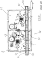
- reference numeral (100) denotes the machine for filling and closing pharmaceutical containers, such as syringes, vials and the like of the present invention.
- the pharmaceutical containers (CF) to be filled and closed are arranged in relative support elements (E), being trays, or are arranged in nests (N) inserted into relative tubs (T), as illustrated in figure 1A .
- the machine (100) of the invention is predisposed to operate with both types of support elements.
- the machine (100) comprises a conveyor means (1) predisposed for receiving and conveying the support elements (E) of the pharmaceutical containers, and a work environment (2) which is maintained, in known ways, in a controlled and sterile atmosphere comprising an inlet passage (21) and an outlet passage (22).
- the conveyor means (1) is arranged with respect to the work environment (2) and is configured so as to have a length that is such as to cross the work environment (2) through the inlet passage (21) and the outlet passage (22) and to have: a first portion (11) externally of the work environment (2) and upstream of the inlet passage (21), for receiving the support elements (E) of the pharmaceutical containers which are to be filled with pharmaceutical substances or products and then closed, a second portion (12) internally of the work environment (2), between the inlet passage (21) and the outlet passage (22), to which the conveyor means (1) conveys and positions the support elements (E) of the pharmaceutical containers to be filled and closed, and lastly a third portion (13) externally of the work environment (2) downstream of the outlet passage (22).
- the machine (100) further comprises a collecting station (3) located internally of the work environment (2), which is predisposed and configured for collecting and extracting the pharmaceutical containers from the support elements (E) which have been conveyed by the conveyor organ (1) through the inlet passage (21) at the relative second portion (12).
- a collecting station (3) located internally of the work environment (2), which is predisposed and configured for collecting and extracting the pharmaceutical containers from the support elements (E) which have been conveyed by the conveyor organ (1) through the inlet passage (21) at the relative second portion (12).
- the peculiarities of the machine (100) for filling and closing the pharmaceutical containers of the present invention consist in the fact that the work environment (2) further comprises a second outlet passage (23) and the machine (100) further comprises a second work environment (4) maintained in a controlled and sterile atmosphere.
- the second work environment (4) comprises and inlet (41) and an outlet (42), and is predisposed with respect to the work environment (2) in such a way that the inlet (41) is at the second outlet passage (23) of the work environment (2) so as to identify a common passage (P) between the two work environments (2, 4)
- the machine (100) also comprises a conveyor (5) which is predisposed and positioned so as to pass through the common passage (P) and to have a first part (51) located internally of the work environment (2) and a second part (52) which is located internally of the second work environment (4).
- the conveyor (5) is configured and predisposed so that the first part (51) (located internally of the work environment (2)) can receive the pharmaceutical containers extracted from the support elements (E) at the collecting station (3) and so that the pharmaceutical containers can be conveyed through the common passage (P) internally of the second work environment (4) at, and along, the second part (52) of the conveyor (5).
- the conveyor (5) can be provided with special retaining elements or seatings (not illustrated in detail as of known type) in which the containers can be positioned and retained during transport thereof along the conveyor (5), from the first part (51) internally of the work environment (2) to the second part (52), through the common passage (P), and along the second part (52) internally of the second work environment (4).
- the machine (100) is provided and equipped with:
- the machine (100) comprises extraction means (8), which are predisposed for collecting the pharmaceutical containers that have been filled and closed from the conveyor (5) and for transporting the containers externally of the second work environment (4) through the relative outlet (42).
- the pharmaceutical containers once extracted from the relative support elements at the collecting station (3) in the work environment (2), can be transferred internally of the second work environment (4) and be filled and closed there.
- the filling and closing of the pharmaceutical containers can take place in a sterile work environment that is entirely separated and distinct from the work environment in which the support elements are positioned and moved.
- the machine (100) is predisposed to be able to operate both when the pharmaceutical containers are arranged in support elements (E) constituted by nests (N) inserted in and borne by relative tubs (T), and when the pharmaceutical containers are arranged in trays.
- figures 2 and 3 illustrate a preferred embodiment of the machine (100) of the invention in the case of support elements (E) constituted by nests (N) which bear a plurality of pharmaceutical containers (CF), such as for example syringes or vials and a tub (T) in which the nest (N) is positioned.
- support elements (E) constituted by nests (N) which bear a plurality of pharmaceutical containers (CF), such as for example syringes or vials and a tub (T) in which the nest (N) is positioned.
- CF pharmaceutical containers
- T tub
- the collecting station (3) comprises: transfer means (31), which are predisposed for collecting the nests (N) from the tubs (T) of the support elements (E) which have been conveyed by the conveyor means (1) through the inlet passage (21) to the relative second portion (12) internally of the work environment (2) and for positioning the nests (N) at a paused position (Z) in proximity of the first part (51) of the conveyor (5).
- the collecting station (3) also comprises handling organs (32) which are predisposed and configured for collecting the pharmaceutical containers from the nests positioned in the paused position (Z) and transfer the containers onto the first part (51) of the conveyor (5).
- the transfer means (31) are also predisposed for collecting the nests (N) from the paused position (Z), once emptied of the pharmaceutical containers, and for newly transferring the containers into the tubs (T) present on the second portion (12) of the conveyor means (1).
- the conveyor means (1) can convey the support elements (E), once emptied, externally of the work environment (2) through the outlet passage (22) and along the relative third portion (13).
- the transfer means of the collecting station (3) will be configured and predisposed to extract the pharmaceutical containers directly from the trays, which have been conveyed by the conveyor means (1) through the inlet passage (21) to the relative second portion (12) internally of the work environment (2) and for positioning the pharmaceutical containers at a paused position (Z) in proximity of the first part (51) of the conveyor(5).
- the collecting station (3) will be provided with special handling organs (32) predisposed and configured for collecting the pharmaceutical containers from the paused position (Z) and transferring the containers onto the first part (51) of the conveyor (5).
- the conveyor means (1) can convey the trays, once emptied, externally of the work environment (2) through the outlet passage (22) and along the relative third portion (13).
- the extraction means (8) comprise gripping means (81), predisposed for collecting the pharmaceutical containers that have been filled and closed from the conveyor (5), and a screw transport member (82) for receiving the pharmaceutical containers from the gripping means (81) and for conveying the pharmaceutical containers externally of the second work environment (4) through the relative outlet (42).
- the machine (100) can advantageously comprise, as illustrated schematically in figure 2 , a sorting station (9), arranged downstream of the outlet (42) of the second work environment (4).
- the sorting station (9) is predisposed for receiving the filled and closed pharmaceutical containers from the extraction means (8) and for transferring the pharmaceutical containers to a packing station (90).
- the machine (100) is designed and structured so that the third portion (13) of the conveyor means (1) can be configured for conveying the support elements (E), once emptied of the pharmaceutical containers, up to the packing station (90).
- the machine (100) can be configured so that the packing station (90) comprises pick up and place organs (91) which are predisposed for collecting the pharmaceutical containers supplied by the sorting station (9) and inserting the pharmaceutical containers internally of the support elements (E).
Landscapes
- Engineering & Computer Science (AREA)
- Mechanical Engineering (AREA)
- Health & Medical Sciences (AREA)
- Animal Behavior & Ethology (AREA)
- Pharmacology & Pharmacy (AREA)
- Life Sciences & Earth Sciences (AREA)
- Hematology (AREA)
- General Health & Medical Sciences (AREA)
- Public Health (AREA)
- Veterinary Medicine (AREA)
- Basic Packing Technique (AREA)
- Filling Of Jars Or Cans And Processes For Cleaning And Sealing Jars (AREA)
- Medical Preparation Storing Or Oral Administration Devices (AREA)
Claims (6)
- Une machine (100) pour remplir et fermer des récipients pharmaceutiques (CF), tels que des seringues, des flacons et similaires, disposés dans des éléments de support (E) correspondants, comprenant:un moyen transporteur (1) prédisposé pour recevoir et transporter les éléments de support (E) des récipients pharmaceutiques ;un environnement de travail (2) dans une atmosphère contrôlée et stérile comprenant un passage d'entrée (21) et un passage de sortie (22),le moyen transporteur (1) étant disposé par rapport à l'environnement de travail (2) et ayant une longueur qui est telle qu'il traverse l'environnement de travail (2) à travers le passage d'entrée (21) et le passage de sortie (22) et qu'il a : une première portion (11) à l'extérieur de l'environnement de travail (2) et en amont du passage d'entrée (21), pour recevoir les éléments de support (E) des récipients pharmaceutiques qui doivent être remplis avec des substances ou produits pharmaceutiques puis fermés, une deuxième portion (12) à l'intérieur de l'environnement de travail (2), entre le passage d'entrée (21) et le passage de sortie (22), au niveau de laquelle le moyen transporteur (1) transporte et positionne les éléments de support (E) des récipients pharmaceutiques à remplir et fermer, et une troisième portion (13) à l'extérieur de l'environnement de travail (2) en aval du passage de sortie (22),une station de prélèvement (3) à l'intérieur de l'environnement de travail (2) et prédisposée et configurée pour prélever et extraire les récipients pharmaceutiques des éléments de support (E) qui ont été transportés par le moyen transporteur (1) à travers le passage d'entrée (21) au niveau de la deuxième portion (12) correspondante,caractérisée en ce que l'environnement de travail (2) comprend un deuxième passage de sortie (23) et en ce qu'elle comprend un deuxième environnement de travail (4) dans une atmosphère contrôlée et stérile comprenant une entrée (41) et une sortie (42), le deuxième environnement de travail (4) étant prédisposé par rapport à l'environnement de travail (2) de manière à ce que l'entrée (41) soit au niveau du deuxième passage de sortie (23) de l'environnement de travail (2) de manière à identifier un passage commun (P) entre les deux environnements de travail (2, 4), et en ce qu'elle comprend :un convoyeur (5) prédisposé et positionné de manière à passer à travers le passage commun (P) et à avoir une première partie (51) située à l'intérieur de l'environnement de travail (2) et une deuxième partie (52) située à l'intérieur du deuxième environnement de travail (4), et prédisposé de manière à ce que la première partie (51) puisse recevoir les récipients pharmaceutiques extraits des éléments de support (E) au niveau de la station de prélèvement (3) et de manière à ce que les récipients pharmaceutiques puissent être transportés à travers le passage commun (P) à l'intérieur du deuxième environnement de travail (4) au niveau de, et le long de, la deuxième partie (52) du convoyeur (5),une station de remplissage (6), à l'intérieur du deuxième environnement de travail (4), pour effectuer le remplissage des récipients pharmaceutiques transportés par la deuxième partie (52) du convoyeur (5) avec des substances ou produits pharmaceutiques,une station de fermeture (7), à l'intérieur du deuxième environnement de travail (4), pour appliquer un élément de fermeture sur les récipients pharmaceutiques une fois remplis,des moyens d'extraction (8), prédisposés pour prélever les récipients pharmaceutiques qui ont été remplis et fermés du convoyeur (5) et pour transporter les récipients à l'extérieur du deuxième environnement de travail (4) à travers la sortie (42) correspondante.
- La machine (100) pour remplir et fermer des récipients pharmaceutiques selon la revendication 1, dans laquelle les éléments de support (E) des récipients pharmaceutiques comprennent un nest (N) qui porte une pluralité de récipients pharmaceutiques et un tub (T) dans lequel le nest (N) est positionné, et dans laquelle la station de prélèvement (3) comprend : des moyens de transfert (31) prédisposés pour prélever les nests (N) des tubs (T) des éléments de supports (E) qui ont été transportés par le moyen transporteur (1) à travers le passage d'entrée (21) au niveau de la deuxième portion (12) correspondante à l'intérieur de l'environnement de travail (2) et pour positionner les nests (N) au niveau d'une position de pause (Z) à proximité de la première partie (51) du convoyeur (5), et des moyens de manipulation (32) prédisposés et configurés pour prélever les récipients pharmaceutiques des nests positionnés dans la position de pause (Z) et transférer les récipients sur la première partie (51) du convoyeur (5), les moyens de transfert (31) étant également prédisposés pour prélever les nests (N), une fois vidés des produits pharmaceutiques, et pour transférer à nouveau les nests dans les tubs (T) présents sur la deuxième portion (12) du moyen transporteur (1).
- La machine (100) pour remplir et fermer des récipients pharmaceutiques selon la revendication 1, dans laquelle les éléments de support (E) des récipients pharmaceutiques comprennent un plateau et les récipients pharmaceutiques sont disposés à l'intérieur du plateau, et dans laquelle la station de prélèvement (3) comprend des moyens de transfert pour extraire les récipients pharmaceutiques des plateaux qui ont été transportés par le moyen transporteur (1) à travers le passage d'entrée (21) au niveau de la deuxième portion (12) correspondante à l'intérieur de l'environnement de travail (2) et pour positionner les récipients pharmaceutiques au niveau d'une position de pause (Z) à proximité de la première partie (51) du convoyeur (5), et des moyens de manipulation (32) prédisposés et configurés pour prélever les récipients pharmaceutiques de la position de pause (Z) et transférer les récipients sur la première partie (51) du convoyeur (5).
- La machine (100) pour remplir et fermer des récipients pharmaceutiques selon l'une quelconque des revendications précédentes, dans laquelle les moyens d'extraction (8) comprennent des moyens de préhension (81), prédisposés pour prélever les récipients pharmaceutiques qui ont été remplis et fermés du convoyeur (5), et un organe de transport à vis (82) pour recevoir les récipients pharmaceutiques des moyens de préhension (81) et pour transporter les récipients pharmaceutiques à l'extérieur du deuxième environnement de travail (4) à travers la sortie (42) correspondante.
- La machine (100) pour remplir et fermer des récipients pharmaceutiques selon l'une quelconque des revendications précédentes, caractérisée en ce qu'elle comprend une station de tri (9), en aval de la sortie (42) du deuxième environnement de travail (4), prédisposée pour recevoir les récipients pharmaceutiques remplis et fermés des moyens d'extraction (8) et pour transférer les récipients pharmaceutiques à une station d'emballage (90).
- La machine (100) pour remplir et fermer des récipients pharmaceutiques selon la revendication 5, dans laquelle le moyen transporteur (1) est configuré pour transporter les éléments de support (E), une fois vidés des récipients pharmaceutiques, à l'extérieur de l'environnement de travail (2) à travers le passage de sortie (22) et le long de la troisième portion (13) correspondante jusqu'à la station d'emballage (90), et dans laquelle la station d'emballage (90) comprend des organes de prise et de dépose (91) prédisposés pour insérer les récipients pharmaceutiques remplis et fermés de nouveau à l'intérieur des éléments de support (E).
Applications Claiming Priority (2)
| Application Number | Priority Date | Filing Date | Title |
|---|---|---|---|
| IT102018000004068A IT201800004068A1 (it) | 2018-03-29 | 2018-03-29 | Macchina per il riempimento e la chiusura di contenitori farmaceutici, quali siringhe, flaconi e simili |
| PCT/IB2019/052115 WO2019186318A1 (fr) | 2018-03-29 | 2019-03-15 | Machine pour remplir et fermer des récipients pharmaceutiques, tels que des seringues, des flacons et similaires |
Publications (2)
| Publication Number | Publication Date |
|---|---|
| EP3774555A1 EP3774555A1 (fr) | 2021-02-17 |
| EP3774555B1 true EP3774555B1 (fr) | 2021-07-21 |
Family
ID=62875087
Family Applications (1)
| Application Number | Title | Priority Date | Filing Date |
|---|---|---|---|
| EP19721031.3A Active EP3774555B1 (fr) | 2018-03-29 | 2019-03-15 | Machine pour remplir et fermer des récipients pharmaceutiques, tels que des seringues, des flacons et similaires |
Country Status (7)
| Country | Link |
|---|---|
| US (1) | US11434027B2 (fr) |
| EP (1) | EP3774555B1 (fr) |
| KR (1) | KR102670341B1 (fr) |
| CN (1) | CN111902342B (fr) |
| ES (1) | ES2892481T3 (fr) |
| IT (1) | IT201800004068A1 (fr) |
| WO (1) | WO2019186318A1 (fr) |
Families Citing this family (2)
| Publication number | Priority date | Publication date | Assignee | Title |
|---|---|---|---|---|
| DE102021207742A1 (de) | 2021-07-20 | 2023-01-26 | KyooBe Tech GmbH | Produktionsanlage und Verfahren zur Herstellung eines Produkts |
| DE102024121673A1 (de) * | 2024-07-30 | 2026-02-05 | Bausch + Ströbel SE + Co. KG | Vorrichtung zum Verarbeiten pharmazeutischer Behälter |
Family Cites Families (25)
| Publication number | Priority date | Publication date | Assignee | Title |
|---|---|---|---|---|
| US5577367A (en) * | 1994-06-10 | 1996-11-26 | Johnson & Johnson Vision Products, Inc. | Apparatus and method for sterilization and secondary packaging |
| JP4216467B2 (ja) * | 1998-03-13 | 2009-01-28 | ベクトン・ディキンソン・アンド・カンパニー | 医療装置の組立ておよび包装方法 |
| EP2433871A3 (fr) * | 2002-06-19 | 2012-07-11 | Medical Instill Technologies, Inc. | Machine de remplissage stérile comprenant une station de remplissage par aiguille à l'interieur d'une chambre à faisceau d'electrons |
| GB0304386D0 (en) * | 2003-02-25 | 2003-04-02 | Glaxosmithkline Biolog Sa | Novel process |
| US7096896B2 (en) * | 2004-03-05 | 2006-08-29 | Medical Instill Technologies, Inc. | Apparatus and method for needle filling and laser resealing |
| JP4603475B2 (ja) | 2005-12-02 | 2010-12-22 | 一般財団法人化学及血清療法研究所 | シリンジパッケージ装置およびそれを備えたプレフィルドシリンジ製造装置 |
| ITBO20060183A1 (it) * | 2006-03-15 | 2007-09-16 | Pietro Dovesi | Metodo per il confezionamento di flaconi in ambiente sterile ed apparato che attua tale metodo |
| SE529732C2 (sv) * | 2006-03-21 | 2007-11-06 | Tetra Laval Holdings & Finance | Sätt att förpacka och i hållbarhetsförlängande syfte värmebehandla ett livsmedel |
| ITBO20060246A1 (it) * | 2006-04-05 | 2007-10-06 | Ima Spa | Apparato e metodo per alimentare con un prodotto una macchina confezionatrice. |
| US9296600B2 (en) * | 2007-07-11 | 2016-03-29 | Stokely-Van Camp, Inc. | Active sterilization zone for container filling |
| DE102008001287A1 (de) | 2008-04-21 | 2009-10-22 | Robert Bosch Gmbh | Füll- und Verschließmaschine für Behälter |
| DE102009027452A1 (de) * | 2009-07-03 | 2011-01-05 | Robert Bosch Gmbh | Vorrichtung zum Füllen und Verschließen von pharmazeutischen Bahältnissen |
| IT1400953B1 (it) * | 2010-06-14 | 2013-07-05 | Marchesini Group Spa | Macchina per il confezionamento di flaconi |
| US9466088B2 (en) * | 2010-09-17 | 2016-10-11 | National Instrument, Llc | Automated oral syringe packaging system for hospital pharmacies |
| JP2012116495A (ja) | 2010-11-30 | 2012-06-21 | Kazuto Hanazono | 医薬品の製造装置 |
| US9675519B2 (en) * | 2011-01-28 | 2017-06-13 | Aquavit Pharmaceuticals, Inc. | System and method for personalized injection treatment |
| DE102011119657B4 (de) * | 2011-11-29 | 2015-03-12 | Gerhard Schubert Gmbh | Verpackungsmaschine für keimfreies Abpacken |
| KR20170138590A (ko) * | 2012-04-13 | 2017-12-15 | 닥터.피와이 인스터튜트, 엘엘씨 | 모듈라 충전 장치 및 방법 |
| TW201900139A (zh) * | 2013-08-16 | 2019-01-01 | 加拿大商凡爾克斯醫藥系統公司 | 用於裝填藥物容器的方法、裝置及系統 |
| KR102274424B1 (ko) * | 2013-09-19 | 2021-07-07 | 가부시키가이샤 유야마 세이사쿠쇼 | 혼주 장치, 혼주 방법 |
| DE102014214697A1 (de) * | 2014-07-25 | 2016-01-28 | Robert Bosch Gmbh | Vorrichtung zum Befüllen eines Behältnisses |
| JP6911257B2 (ja) * | 2015-06-11 | 2021-07-28 | アイ.エム.エー. インダストリア マシーン オートマチック エス.ピー.エー. イン シグラ アイエムエー エス.ピー.エー.I.M.A. Industria Macchine Automatiche S.P.A In Sigla Ima S.P.A | ビン、カートリッジ、シリンジなどの充填および密封の為の方法および機械 |
| CN105540520B (zh) * | 2015-12-31 | 2017-08-04 | 楚天科技股份有限公司 | 一种预灌封注射器灌装机 |
| DE102016103404A1 (de) * | 2016-02-26 | 2017-08-31 | Schott Ag | Verfahren zum Überführen einer Mehrzahl von Behältern zur Aufbewahrung von Substanzen für medizinische, pharmazeutische oder kosmetische Zwecke in einen Reinraum, Transport- und Verpackungsbehälter und Verpackungsgebilde hierfür sowie Verwendung |
| DK3335844T3 (da) * | 2016-12-15 | 2020-01-06 | Pharma Integration S R L | Konstruktiv struktur af en indeslutning bestemt til automatiseret produktion af farmaceutiske eller biotekniske artikler |
-
2018
- 2018-03-29 IT IT102018000004068A patent/IT201800004068A1/it unknown
-
2019
- 2019-03-15 KR KR1020207028847A patent/KR102670341B1/ko active Active
- 2019-03-15 WO PCT/IB2019/052115 patent/WO2019186318A1/fr not_active Ceased
- 2019-03-15 EP EP19721031.3A patent/EP3774555B1/fr active Active
- 2019-03-15 US US16/980,556 patent/US11434027B2/en active Active
- 2019-03-15 CN CN201980021179.XA patent/CN111902342B/zh active Active
- 2019-03-15 ES ES19721031T patent/ES2892481T3/es active Active
Also Published As
| Publication number | Publication date |
|---|---|
| US11434027B2 (en) | 2022-09-06 |
| IT201800004068A1 (it) | 2019-09-29 |
| ES2892481T3 (es) | 2022-02-04 |
| US20210002007A1 (en) | 2021-01-07 |
| KR20200139169A (ko) | 2020-12-11 |
| CN111902342B (zh) | 2022-03-29 |
| EP3774555A1 (fr) | 2021-02-17 |
| WO2019186318A1 (fr) | 2019-10-03 |
| CN111902342A (zh) | 2020-11-06 |
| KR102670341B1 (ko) | 2024-05-28 |
Similar Documents
| Publication | Publication Date | Title |
|---|---|---|
| US10954008B2 (en) | Method for handling primary containers for pharmaceutical use transported along an automatic treatment line operating in a controlled environment | |
| EP3307629B1 (fr) | Procédé et machine pour remplir et sceller des bouteilles, des cartouches, des seringues, et analogues | |
| US10329041B2 (en) | System and method for the assembly and collection of non-filled spouted pouches | |
| US12024322B2 (en) | Apparatus for extracting pharmaceutical containers from support elements | |
| EP3490890B1 (fr) | Ensemble convoyeur pour emballages de récipients à usage pharmaceutique | |
| US11325736B2 (en) | Extraction assembly of a content from a bag for pharmaceutical and chemical sectors | |
| US11434027B2 (en) | Machine for filling and closing pharmaceutical containers, such as syringes, vials and the like | |
| WO2011093729A1 (fr) | Procédé et appareil pour l'emballage en sacs de produits | |
| RU2715960C2 (ru) | Система и способ для транспортировки пакетов | |
| US20180257803A1 (en) | Method for automatically inserting enclosures into a receptacle and a device for carrying out the method | |
| ES1256016U (es) | Instalacion para llenar envases vacios sin tapon | |
| US20110214965A1 (en) | Medical guide leaflet insertion device | |
| CA3032119C (fr) | Ensemble d'extraction d'un contenu d'un sac pour les secteurs pharmaceutique et chimique | |
| JPS6216303A (ja) | 被包体集積包装機 |
Legal Events
| Date | Code | Title | Description |
|---|---|---|---|
| STAA | Information on the status of an ep patent application or granted ep patent |
Free format text: STATUS: UNKNOWN |
|
| STAA | Information on the status of an ep patent application or granted ep patent |
Free format text: STATUS: THE INTERNATIONAL PUBLICATION HAS BEEN MADE |
|
| PUAI | Public reference made under article 153(3) epc to a published international application that has entered the european phase |
Free format text: ORIGINAL CODE: 0009012 |
|
| STAA | Information on the status of an ep patent application or granted ep patent |
Free format text: STATUS: REQUEST FOR EXAMINATION WAS MADE |
|
| 17P | Request for examination filed |
Effective date: 20201026 |
|
| AK | Designated contracting states |
Kind code of ref document: A1 Designated state(s): AL AT BE BG CH CY CZ DE DK EE ES FI FR GB GR HR HU IE IS IT LI LT LU LV MC MK MT NL NO PL PT RO RS SE SI SK SM TR |
|
| AX | Request for extension of the european patent |
Extension state: BA ME |
|
| GRAP | Despatch of communication of intention to grant a patent |
Free format text: ORIGINAL CODE: EPIDOSNIGR1 |
|
| STAA | Information on the status of an ep patent application or granted ep patent |
Free format text: STATUS: GRANT OF PATENT IS INTENDED |
|
| DAV | Request for validation of the european patent (deleted) | ||
| DAX | Request for extension of the european patent (deleted) | ||
| INTG | Intention to grant announced |
Effective date: 20210225 |
|
| GRAS | Grant fee paid |
Free format text: ORIGINAL CODE: EPIDOSNIGR3 |
|
| GRAA | (expected) grant |
Free format text: ORIGINAL CODE: 0009210 |
|
| STAA | Information on the status of an ep patent application or granted ep patent |
Free format text: STATUS: THE PATENT HAS BEEN GRANTED |
|
| RIN1 | Information on inventor provided before grant (corrected) |
Inventor name: ANATRINI, DARIO Inventor name: TERROSI, ANDREA |
|
| AK | Designated contracting states |
Kind code of ref document: B1 Designated state(s): AL AT BE BG CH CY CZ DE DK EE ES FI FR GB GR HR HU IE IS IT LI LT LU LV MC MK MT NL NO PL PT RO RS SE SI SK SM TR |
|
| REG | Reference to a national code |
Ref country code: GB Ref legal event code: FG4D |
|
| REG | Reference to a national code |
Ref country code: CH Ref legal event code: EP |
|
| REG | Reference to a national code |
Ref country code: DE Ref legal event code: R096 Ref document number: 602019006306 Country of ref document: DE |
|
| REG | Reference to a national code |
Ref country code: AT Ref legal event code: REF Ref document number: 1412410 Country of ref document: AT Kind code of ref document: T Effective date: 20210815 |
|
| REG | Reference to a national code |
Ref country code: IE Ref legal event code: FG4D |
|
| REG | Reference to a national code |
Ref country code: LT Ref legal event code: MG9D |
|
| REG | Reference to a national code |
Ref country code: NL Ref legal event code: MP Effective date: 20210721 |
|
| REG | Reference to a national code |
Ref country code: AT Ref legal event code: MK05 Ref document number: 1412410 Country of ref document: AT Kind code of ref document: T Effective date: 20210721 |
|
| PG25 | Lapsed in a contracting state [announced via postgrant information from national office to epo] |
Ref country code: LT Free format text: LAPSE BECAUSE OF FAILURE TO SUBMIT A TRANSLATION OF THE DESCRIPTION OR TO PAY THE FEE WITHIN THE PRESCRIBED TIME-LIMIT Effective date: 20210721 Ref country code: AT Free format text: LAPSE BECAUSE OF FAILURE TO SUBMIT A TRANSLATION OF THE DESCRIPTION OR TO PAY THE FEE WITHIN THE PRESCRIBED TIME-LIMIT Effective date: 20210721 Ref country code: BG Free format text: LAPSE BECAUSE OF FAILURE TO SUBMIT A TRANSLATION OF THE DESCRIPTION OR TO PAY THE FEE WITHIN THE PRESCRIBED TIME-LIMIT Effective date: 20211021 Ref country code: FI Free format text: LAPSE BECAUSE OF FAILURE TO SUBMIT A TRANSLATION OF THE DESCRIPTION OR TO PAY THE FEE WITHIN THE PRESCRIBED TIME-LIMIT Effective date: 20210721 Ref country code: HR Free format text: LAPSE BECAUSE OF FAILURE TO SUBMIT A TRANSLATION OF THE DESCRIPTION OR TO PAY THE FEE WITHIN THE PRESCRIBED TIME-LIMIT Effective date: 20210721 Ref country code: PT Free format text: LAPSE BECAUSE OF FAILURE TO SUBMIT A TRANSLATION OF THE DESCRIPTION OR TO PAY THE FEE WITHIN THE PRESCRIBED TIME-LIMIT Effective date: 20211122 Ref country code: NL Free format text: LAPSE BECAUSE OF FAILURE TO SUBMIT A TRANSLATION OF THE DESCRIPTION OR TO PAY THE FEE WITHIN THE PRESCRIBED TIME-LIMIT Effective date: 20210721 Ref country code: NO Free format text: LAPSE BECAUSE OF FAILURE TO SUBMIT A TRANSLATION OF THE DESCRIPTION OR TO PAY THE FEE WITHIN THE PRESCRIBED TIME-LIMIT Effective date: 20211021 Ref country code: SE Free format text: LAPSE BECAUSE OF FAILURE TO SUBMIT A TRANSLATION OF THE DESCRIPTION OR TO PAY THE FEE WITHIN THE PRESCRIBED TIME-LIMIT Effective date: 20210721 Ref country code: RS Free format text: LAPSE BECAUSE OF FAILURE TO SUBMIT A TRANSLATION OF THE DESCRIPTION OR TO PAY THE FEE WITHIN THE PRESCRIBED TIME-LIMIT Effective date: 20210721 |
|
| REG | Reference to a national code |
Ref country code: ES Ref legal event code: FG2A Ref document number: 2892481 Country of ref document: ES Kind code of ref document: T3 Effective date: 20220204 |
|
| PG25 | Lapsed in a contracting state [announced via postgrant information from national office to epo] |
Ref country code: PL Free format text: LAPSE BECAUSE OF FAILURE TO SUBMIT A TRANSLATION OF THE DESCRIPTION OR TO PAY THE FEE WITHIN THE PRESCRIBED TIME-LIMIT Effective date: 20210721 Ref country code: LV Free format text: LAPSE BECAUSE OF FAILURE TO SUBMIT A TRANSLATION OF THE DESCRIPTION OR TO PAY THE FEE WITHIN THE PRESCRIBED TIME-LIMIT Effective date: 20210721 Ref country code: GR Free format text: LAPSE BECAUSE OF FAILURE TO SUBMIT A TRANSLATION OF THE DESCRIPTION OR TO PAY THE FEE WITHIN THE PRESCRIBED TIME-LIMIT Effective date: 20211022 |
|
| REG | Reference to a national code |
Ref country code: DE Ref legal event code: R097 Ref document number: 602019006306 Country of ref document: DE |
|
| PG25 | Lapsed in a contracting state [announced via postgrant information from national office to epo] |
Ref country code: DK Free format text: LAPSE BECAUSE OF FAILURE TO SUBMIT A TRANSLATION OF THE DESCRIPTION OR TO PAY THE FEE WITHIN THE PRESCRIBED TIME-LIMIT Effective date: 20210721 |
|
| PLBE | No opposition filed within time limit |
Free format text: ORIGINAL CODE: 0009261 |
|
| STAA | Information on the status of an ep patent application or granted ep patent |
Free format text: STATUS: NO OPPOSITION FILED WITHIN TIME LIMIT |
|
| PG25 | Lapsed in a contracting state [announced via postgrant information from national office to epo] |
Ref country code: SM Free format text: LAPSE BECAUSE OF FAILURE TO SUBMIT A TRANSLATION OF THE DESCRIPTION OR TO PAY THE FEE WITHIN THE PRESCRIBED TIME-LIMIT Effective date: 20210721 Ref country code: SK Free format text: LAPSE BECAUSE OF FAILURE TO SUBMIT A TRANSLATION OF THE DESCRIPTION OR TO PAY THE FEE WITHIN THE PRESCRIBED TIME-LIMIT Effective date: 20210721 Ref country code: RO Free format text: LAPSE BECAUSE OF FAILURE TO SUBMIT A TRANSLATION OF THE DESCRIPTION OR TO PAY THE FEE WITHIN THE PRESCRIBED TIME-LIMIT Effective date: 20210721 Ref country code: EE Free format text: LAPSE BECAUSE OF FAILURE TO SUBMIT A TRANSLATION OF THE DESCRIPTION OR TO PAY THE FEE WITHIN THE PRESCRIBED TIME-LIMIT Effective date: 20210721 Ref country code: CZ Free format text: LAPSE BECAUSE OF FAILURE TO SUBMIT A TRANSLATION OF THE DESCRIPTION OR TO PAY THE FEE WITHIN THE PRESCRIBED TIME-LIMIT Effective date: 20210721 Ref country code: AL Free format text: LAPSE BECAUSE OF FAILURE TO SUBMIT A TRANSLATION OF THE DESCRIPTION OR TO PAY THE FEE WITHIN THE PRESCRIBED TIME-LIMIT Effective date: 20210721 |
|
| 26N | No opposition filed |
Effective date: 20220422 |
|
| PG25 | Lapsed in a contracting state [announced via postgrant information from national office to epo] |
Ref country code: MC Free format text: LAPSE BECAUSE OF FAILURE TO SUBMIT A TRANSLATION OF THE DESCRIPTION OR TO PAY THE FEE WITHIN THE PRESCRIBED TIME-LIMIT Effective date: 20210721 |
|
| REG | Reference to a national code |
Ref country code: CH Ref legal event code: PL |
|
| REG | Reference to a national code |
Ref country code: BE Ref legal event code: MM Effective date: 20220331 |
|
| PG25 | Lapsed in a contracting state [announced via postgrant information from national office to epo] |
Ref country code: LU Free format text: LAPSE BECAUSE OF NON-PAYMENT OF DUE FEES Effective date: 20220315 Ref country code: LI Free format text: LAPSE BECAUSE OF NON-PAYMENT OF DUE FEES Effective date: 20220331 Ref country code: IE Free format text: LAPSE BECAUSE OF NON-PAYMENT OF DUE FEES Effective date: 20220315 Ref country code: CH Free format text: LAPSE BECAUSE OF NON-PAYMENT OF DUE FEES Effective date: 20220331 |
|
| PG25 | Lapsed in a contracting state [announced via postgrant information from national office to epo] |
Ref country code: BE Free format text: LAPSE BECAUSE OF NON-PAYMENT OF DUE FEES Effective date: 20220331 |
|
| P01 | Opt-out of the competence of the unified patent court (upc) registered |
Effective date: 20230329 |
|
| GBPC | Gb: european patent ceased through non-payment of renewal fee |
Effective date: 20230315 |
|
| PG25 | Lapsed in a contracting state [announced via postgrant information from national office to epo] |
Ref country code: GB Free format text: LAPSE BECAUSE OF NON-PAYMENT OF DUE FEES Effective date: 20230315 |
|
| PG25 | Lapsed in a contracting state [announced via postgrant information from national office to epo] |
Ref country code: GB Free format text: LAPSE BECAUSE OF NON-PAYMENT OF DUE FEES Effective date: 20230315 |
|
| PG25 | Lapsed in a contracting state [announced via postgrant information from national office to epo] |
Ref country code: MK Free format text: LAPSE BECAUSE OF FAILURE TO SUBMIT A TRANSLATION OF THE DESCRIPTION OR TO PAY THE FEE WITHIN THE PRESCRIBED TIME-LIMIT Effective date: 20210721 Ref country code: CY Free format text: LAPSE BECAUSE OF FAILURE TO SUBMIT A TRANSLATION OF THE DESCRIPTION OR TO PAY THE FEE WITHIN THE PRESCRIBED TIME-LIMIT Effective date: 20210721 |
|
| PG25 | Lapsed in a contracting state [announced via postgrant information from national office to epo] |
Ref country code: HU Free format text: LAPSE BECAUSE OF FAILURE TO SUBMIT A TRANSLATION OF THE DESCRIPTION OR TO PAY THE FEE WITHIN THE PRESCRIBED TIME-LIMIT; INVALID AB INITIO Effective date: 20190315 |
|
| PG25 | Lapsed in a contracting state [announced via postgrant information from national office to epo] |
Ref country code: TR Free format text: LAPSE BECAUSE OF FAILURE TO SUBMIT A TRANSLATION OF THE DESCRIPTION OR TO PAY THE FEE WITHIN THE PRESCRIBED TIME-LIMIT Effective date: 20210721 |
|
| PG25 | Lapsed in a contracting state [announced via postgrant information from national office to epo] |
Ref country code: MT Free format text: LAPSE BECAUSE OF FAILURE TO SUBMIT A TRANSLATION OF THE DESCRIPTION OR TO PAY THE FEE WITHIN THE PRESCRIBED TIME-LIMIT Effective date: 20210721 |
|
| PGFP | Annual fee paid to national office [announced via postgrant information from national office to epo] |
Ref country code: IT Payment date: 20250325 Year of fee payment: 7 |
|
| PGFP | Annual fee paid to national office [announced via postgrant information from national office to epo] |
Ref country code: DE Payment date: 20250404 Year of fee payment: 7 |
|
| PGFP | Annual fee paid to national office [announced via postgrant information from national office to epo] |
Ref country code: ES Payment date: 20250403 Year of fee payment: 7 |
|
| PGFP | Annual fee paid to national office [announced via postgrant information from national office to epo] |
Ref country code: FR Payment date: 20260317 Year of fee payment: 8 |