EP3774584B1 - Container with insulating features - Google Patents
Container with insulating features Download PDFInfo
- Publication number
- EP3774584B1 EP3774584B1 EP19784621.5A EP19784621A EP3774584B1 EP 3774584 B1 EP3774584 B1 EP 3774584B1 EP 19784621 A EP19784621 A EP 19784621A EP 3774584 B1 EP3774584 B1 EP 3774584B1
- Authority
- EP
- European Patent Office
- Prior art keywords
- inner sidewall
- outer sleeve
- container
- annular
- spacers
- Prior art date
- Legal status (The legal status is an assumption and is not a legal conclusion. Google has not performed a legal analysis and makes no representation as to the accuracy of the status listed.)
- Active
Links
Images


Classifications
-
- B—PERFORMING OPERATIONS; TRANSPORTING
- B65—CONVEYING; PACKING; STORING; HANDLING THIN OR FILAMENTARY MATERIAL
- B65D—CONTAINERS FOR STORAGE OR TRANSPORT OF ARTICLES OR MATERIALS, e.g. BAGS, BARRELS, BOTTLES, BOXES, CANS, CARTONS, CRATES, DRUMS, JARS, TANKS, HOPPERS, FORWARDING CONTAINERS; ACCESSORIES, CLOSURES, OR FITTINGS THEREFOR; PACKAGING ELEMENTS; PACKAGES
- B65D21/00—Nestable, stackable or joinable containers; Containers of variable capacity
- B65D21/02—Containers specially shaped, or provided with fittings or attachments, to facilitate nesting, stacking, or joining together
- B65D21/0233—Nestable containers
-
- B—PERFORMING OPERATIONS; TRANSPORTING
- B65—CONVEYING; PACKING; STORING; HANDLING THIN OR FILAMENTARY MATERIAL
- B65D—CONTAINERS FOR STORAGE OR TRANSPORT OF ARTICLES OR MATERIALS, e.g. BAGS, BARRELS, BOTTLES, BOXES, CANS, CARTONS, CRATES, DRUMS, JARS, TANKS, HOPPERS, FORWARDING CONTAINERS; ACCESSORIES, CLOSURES, OR FITTINGS THEREFOR; PACKAGING ELEMENTS; PACKAGES
- B65D21/00—Nestable, stackable or joinable containers; Containers of variable capacity
- B65D21/08—Containers of variable capacity
-
- B—PERFORMING OPERATIONS; TRANSPORTING
- B65—CONVEYING; PACKING; STORING; HANDLING THIN OR FILAMENTARY MATERIAL
- B65D—CONTAINERS FOR STORAGE OR TRANSPORT OF ARTICLES OR MATERIALS, e.g. BAGS, BARRELS, BOTTLES, BOXES, CANS, CARTONS, CRATES, DRUMS, JARS, TANKS, HOPPERS, FORWARDING CONTAINERS; ACCESSORIES, CLOSURES, OR FITTINGS THEREFOR; PACKAGING ELEMENTS; PACKAGES
- B65D3/00—Rigid or semi-rigid containers having bodies or peripheral walls of curved or partially-curved cross-section made by winding or bending paper without folding along defined lines
- B65D3/02—Rigid or semi-rigid containers having bodies or peripheral walls of curved or partially-curved cross-section made by winding or bending paper without folding along defined lines characterised by shape
- B65D3/06—Rigid or semi-rigid containers having bodies or peripheral walls of curved or partially-curved cross-section made by winding or bending paper without folding along defined lines characterised by shape essentially conical or frusto-conical
-
- B—PERFORMING OPERATIONS; TRANSPORTING
- B65—CONVEYING; PACKING; STORING; HANDLING THIN OR FILAMENTARY MATERIAL
- B65D—CONTAINERS FOR STORAGE OR TRANSPORT OF ARTICLES OR MATERIALS, e.g. BAGS, BARRELS, BOTTLES, BOXES, CANS, CARTONS, CRATES, DRUMS, JARS, TANKS, HOPPERS, FORWARDING CONTAINERS; ACCESSORIES, CLOSURES, OR FITTINGS THEREFOR; PACKAGING ELEMENTS; PACKAGES
- B65D3/00—Rigid or semi-rigid containers having bodies or peripheral walls of curved or partially-curved cross-section made by winding or bending paper without folding along defined lines
- B65D3/10—Rigid or semi-rigid containers having bodies or peripheral walls of curved or partially-curved cross-section made by winding or bending paper without folding along defined lines characterised by form of integral or permanently secured end closure
- B65D3/12—Flanged discs permanently secured, e.g. by adhesives or by heat-sealing
- B65D3/14—Discs fitting within container end and secured by bending, rolling, or folding operations
-
- B—PERFORMING OPERATIONS; TRANSPORTING
- B65—CONVEYING; PACKING; STORING; HANDLING THIN OR FILAMENTARY MATERIAL
- B65D—CONTAINERS FOR STORAGE OR TRANSPORT OF ARTICLES OR MATERIALS, e.g. BAGS, BARRELS, BOTTLES, BOXES, CANS, CARTONS, CRATES, DRUMS, JARS, TANKS, HOPPERS, FORWARDING CONTAINERS; ACCESSORIES, CLOSURES, OR FITTINGS THEREFOR; PACKAGING ELEMENTS; PACKAGES
- B65D81/00—Containers, packaging elements, or packages, for contents presenting particular transport or storage problems, or adapted to be used for non-packaging purposes after removal of contents
- B65D81/38—Containers, packaging elements, or packages, for contents presenting particular transport or storage problems, or adapted to be used for non-packaging purposes after removal of contents with thermal insulation
- B65D81/3865—Containers, packaging elements, or packages, for contents presenting particular transport or storage problems, or adapted to be used for non-packaging purposes after removal of contents with thermal insulation drinking cups or like containers
- B65D81/3869—Containers, packaging elements, or packages, for contents presenting particular transport or storage problems, or adapted to be used for non-packaging purposes after removal of contents with thermal insulation drinking cups or like containers formed with double walls, i.e. hollow
Definitions
- the present disclosure generally relates to containers for containing fluids, for example, beverage containers.
- the present disclosure relates to a container for heated fluids that includes insulating features.
- US 2018/016052 A1 discloses a dual container that can maintain effective heat insulation and reduce a used amount of thermoplastic resin.
- the dual container has an inner container provided with a tubular barrel portion having a curled portion formed at the upper circumferential edge thereof, and a bottom portion arranged at the lower end of the barrel portion so as to close the lower surface thereof.
- An exterior sleeve covers the barrel portion so as to form a heat insulating space between the outside of the barrel portion. The exterior sleeve is fixed to the barrel portion.
- a plurality of elongated projection portions each of which is made of plastic resin extending elongatedly in the circumferential direction and projecting by 1.0 mm to 2.0 mm are arranged in line over the entire circumference in the circumferential direction, at intervals from one another.
- EP 2 848 554 A2 discloses a double-walled container including an inner sleeve, an outer sleeve and a base.
- the inner sleeve is positioned within the outer sleeve.
- a sidewall cavity may be formed between an inner sleeve sidewall and an outer sleeve sidewall.
- the lower end of the outer sleeve forms an elongated loop located below a lowermost edge of the inner sleeve.
- a flange may extend from the elongated loop upwardly above the lowermost edge of the inner sleeve and is attached to the inner sleeve.
- the elongated loop may form a loop cavity.
- the loop cavity may be in fluid communication with the sidewall cavity.
- US 2008/078825 A1 discloses a container with an inner wall and an outer wall wrapped therearound so as to define a double-wall container construction.
- a plurality of spacer elements are interposed between the inner and the outer walls so as to maintain a minimum thickness of an air space defined therebetween. In normal use conditions, the spacer elements do not contact the inner wall; however, the spacer elements prevent the outer wall from contacting the inner wall during non-standard use conditions.
- the invention is generally directed to containers, sidewall constructs, and methods, as recited in the independent claims. Further embodiments are recited in the dependent claims.
- a container for containing a fluid comprises a sidewall construct, a closed bottom, and insulating features.
- the sidewall construct comprises an inner sidewall extending at least partially around an interior of the container, an outer sleeve attached to the inner sidewall, and a cavity defined between the inner sidewall and the outer sleeve.
- the closed bottom defines a bottom of the interior of the container.
- the insulating features comprise the cavity and a plurality of annular bands, each annular band of the plurality of annular bands comprises a plurality of spacers and a plurality of gaps separating respective adjacent spacers in a respective annular band, each spacer extends in the cavity from the inner sidewall to the outer sleeve.
- a sidewall construct for forming a fluid container comprises an inner sidewall for extending at least partially around an interior of a fluid container formed from the sidewall construct, an outer sleeve attached to the inner sidewall, and a cavity defined between the inner sidewall and the outer sleeve.
- the sidewall construct further comprises insulating features comprising the cavity and a plurality of annular bands, each annular band of the plurality of annular bands comprises a plurality of spacers and a plurality of gaps separating respective adjacent spacers in a respective annular band, each spacer extends in the cavity from the inner sidewall to the outer sleeve.
- a method of forming a container for containing a fluid comprises obtaining an inner sidewall and an outer sleeve and attaching the outer sleeve to the inner sidewall to form a sidewall construct with a cavity defined between the inner sidewall and the outer sleeve.
- the attaching comprises forming insulating features in the sidewall construct, the insulating features comprise the cavity and a plurality of annular bands, each annular band of the plurality of annular bands comprises a plurality of spacers and a plurality of gaps separating respective adjacent spacers in a respective annular band, each spacer extends in the cavity from the inner sidewall to the outer sleeve.
- the method further comprises forming an interior of the fluid container by positioning the sidewall construct so that the inner sidewall extends at least partially around the interior.
- the method further comprises positioning a closed bottom relative to the sidewall construct to define a bottom of the interior.
- Containers according to the present disclosure can accommodate fluids, e.g., beverages, of different sizes and compositions.
- fluids e.g., beverages
- the following detailed description describes a container for heated fluids, e.g., coffee or coffee-based products, tea, hot chocolate, cider, soup, etc. It will be understood that the containers described herein can hold cold beverages or room temperature beverages, and can hold at least partially solid food products, without departing from the disclosure.
- containers can be formed from blanks by overlapping multiple portions, panels, and/or end flaps. Such portions, panels, and/or end flaps may be designated herein in terms relative to one another, e.g., “first”, “second”, “third”, etc., in sequential or non-sequential reference, without departing from the disclosure.
- Fig. 1 is a perspective view
- Fig. 2 is a schematic cross-sectional view, of a fluid vessel or fluid container 5 according to a first exemplary embodiment of the disclosure.
- the container 5 is a cup having the general shape of a truncated cone, with an open top 6, a closed bottom 13, and a sidewall construct 8 extending from a bottom edge to a top edge of the container 5.
- the closed bottom 13 and the sidewall construct 8 define an interior space 7 of the container 5 that is for holding fluids, e.g. hot beverages such as tea, coffee, cider, hot chocolate, etc.
- the sidewall construct 8 comprises an annular inner sidewall 19 (broadly, “inner wall”) and an outer sleeve 23 (broadly, “outer wall”) attached to the inner sidewall 19 such that the sidewall construct 8 can be referred to as a double wall structure.
- the container 5 includes insulating features in the sidewall construct 8 that include radially adjacent spacers 29 separated by respective radial gaps 31.
- the spacers 29 can be at least partially formed from an adhesive, such as a hot melt glue or other glue, and can extend from the inner sidewall 19 to the outer sleeve 23 to adhesively attach the outer sleeve 23 to the inner sidewall 19.
- the spacers 29 can be formed from a different polymeric material.
- the insulating features of the container 5 are arranged such that cost and materials savings can be realized, and so that an insulation profile of the container 5 can be selected so as to be enhanced, for example, so that the fluid in the container 5 can be maintained at a selected or desired temperature or temperature range, and such that a customer can be provided with a more comfortable surface about which to grasp the container 5.
- the bottom 13 of the container 5 includes a generally circular bottom panel 14 and an annular leg 15 foldably connected to and downwardly-depending from the bottom panel 14 at a circular line of weakening 17.
- the annular inner sidewall 19 extends upwardly from the bottom panel 14 to define the interior 7 of the container 5.
- the inner sidewall 19 extends downwardly below the bottom panel 14 to define a lower edge margin 20 thereof, along a portion of which the annular leg 15 is adhesively attached to secure the bottom panel 14 to the inner sidewall 19 and to form the bottom 13 of the interior 7 of the container 5.
- the lower edge margin 20 of the inner sidewall 19 extends along the outer surface of the annular leg 15, wraps under a bottom edge or lower edge thereof, and extends upwardly along the interior surface of the annular leg 15 toward the bottom panel 14.
- the lower edge margin 20 of the inner sidewall 19 can be an at least partially flexible portion of the inner sidewall 19 configured to engage the annular leg 15, and can include surface features to facilitate such engagement, for example, an adhesive treatment and/or frictionally-enhancing patterning.
- the portion of the lower edge margin 20 of the inner sidewall 19 overlying the lower edge of the annular leg 15 will define a bottom edge or lower edge 18 of the inner sidewall 19.
- the lower edge of the annular leg 15 can define the lower edge of the coupled inner sidewall 19 and the bottom 13.
- the bottom 13 can be secured to the sidewall construct 8 in a different configuration without departing from the disclosure.
- an upper portion of the inner sidewall 19 is curved or curled to define a top or upper rim 21 of the container 5 that circumscribes an opening 22 in communication with the interior 7 of the container 5.
- the rim 21 and/or an upper portion of the container 5 can be flanged or otherwise configured to engage a lid or other top container closure structure.
- the bottom 13 of the container 5 can be integrally formed with the inner sidewall 19, e.g., such that the annular leg 15 is integrally formed with the inner sidewall 19, or the bottom 13 can be otherwise attached to a portion of the inner sidewall 19 by other attachment means, for example, crimping, heat sealing, etc.
- the illustrated configuration of the truncated conical shape of the container 5 can be achieved by forming the inner sidewall 19 from a flat blank that is folded around a mandrel such that an overlapping seam is provided, and which can be secured, for example, with an adhesive such as glue.
- the generally truncated conical shape of the sleeve 23 can be formed in a similar manner, or can be formed through a different process without departing from the disclosure.
- the arrangement of the bottom panel 14 and the annular leg 15 of the closed bottom 13 of the container 5 can be formed, in one example, by providing a generally circular blank having an outer periphery that is downwardly folded to provide the annular leg 15 that intersects the bottom panel 14 at the line of weakening 17. It will be understood that the container 5 can have a different configuration and can be formed by other methods and mechanisms without departing from the disclosure.
- the outer sleeve or sleeve 23 e.g., a wrap or other layer, is disposed in at least partial circumferential engagement with the inner sidewall 19 such that the sleeve 23 presents an outer surface of the container 5 for engagement by a customer, e.g., such that the customer can wrap his or her fingers around a portion of the sleeve 23.
- the sleeve 23 can be formed, for example, from materials that include single layer structures, multi-layer structures (with or without inserts therebetween), corrugated materials, etc.
- the sleeve 23 includes an upper edge 25 proximate the rim 21 and a lower edge 27 proximate the lower portion of the inner sidewall 19 generally adjacent the bottom 13.
- at least the interface between the sleeve 23 and the inner sidewall 19 provide insulating features of the container 5 that include a cavity 24 defined between the inner sidewall 19 and the outer sleeve 23.
- the insulating features of the container 5 can also include one or more portions of the inner sidewall 19 and/or the sleeve 23.
- FIG. 3 a front view of the container 5 with the sleeve 23 removed is illustrated.
- a plurality of annular bands B1, B2, B3, B4, B5, B6, and B7 of adhesive are applied around the circumference of the inner sidewall 19 and are positioned between the inner sidewall 19 and the outer sleeve 23 to attach the outer sleeve 23 to the inner sidewall 19 and to form the spacers 29.
- One or more of the annular bands B1, B2, B3, B4, B5, B6, and B7 can be a discontinuous pattern of adhesive such that the bands comprise adhesive that form the spacers 29 that each extend from the inner sidewall 19 to the outer sleeve 23, and the gaps 31 are radially spaced between adjacent spacers 29 along the circumferential length of each of the respective bands around the inner sidewall 19.
- the gaps 31 are sections of each respective band that can be voids, interruptions, or discontinuities of the material that forms the spacers 29 along the bands B1, B2, B3, B4, B5, B6, and B7. It will be understood that a different numbers of bands of spacers 29 can be provided without departing from the disclosure.
- the spacers 29, as shown, can be elongate members, for example, beads, dots, dashes, tracks, trails, and/or other arrangements of material.
- the spacers 29 can be formed of a composite material or polymeric material, such as a hot melt adhesive or other type of adhesive or glue, though the spacers 29 could be material other than adhesive and the outer sleeve 23 could be attached to the inner wall 19 by means other than the annular bands without departing from the disclosure.
- the spacers 29 can provide and/or maintain spacing between the inner sidewall 19 and the sleeve 23, and can additionally provide an attachment, e.g., adhesion, between the inner sidewall 19 and the sleeve 23.
- the spacers 29 have a length L1 corresponding to the length of an arc around the circumference of the portion of the inner sidewall 19 covered by the spacer 29, with the length L1 extending between respective first and second ends 29a, 29b of a spacer 29.
- the gaps 31 have a length L2 corresponding to the length of an arc around the circumference of the portion of the inner sidewall 19 corresponding to the location of the gap that is a portion of the corresponding band that is void of the material that forms the spacers 29, with the length L2 extending from a second end 29b to a first end 29a of adjacent spacers 29.
- the length L1 can be greater than the length L2.
- the length L2 can be greater than the length L1.
- the sum of the lengths L2 of respective gaps 31 of a respective annular band of spacers 29 can correspond to a materials savings of the respective annular band, and by extension, the container 5.
- Such material savings can be represented as a percentage of the material of a comparative annular band having a continuous spacer (i.e., with substantially no gaps therealong), for example, between about 20% and about 80% of such material, such as 20%, 25%, 30%, 35%, 40%, 45%, 50%, 55%, 60%, 65%, 70%, 75%, 80%, or other integer or non-integer numbers therebetween.
- the materials savings of the entire container 5 can be determined by the summation of the material corresponding to the respective lengths L2 of all gaps 31 in the annular bands B1, B2, B3, B4, B5, B6, B7, and can represented as a percentage of material of a summed comparative set of annular bands having respective continuous spacers as described above.
- spacers 29 and the gaps 31 have been shown as having a generally uniform configuration along the container 5, it will be understood that one or more spacers 29 and/or gaps 31 can have a different configuration without departing from the disclosure.
- the spacers 29 and the gaps 31 of the bands B1, B2, B3, B4, B5, B6, B7 are arranged along the inner sidewall 19 such that a plurality of fluid pathways F1, F2 are presented around the spacers 29 and through respective gaps 31 between the upper edge 25 of the sleeve 23 and the lower edge 27 of the sleeve 23 (shown with broken lines in Fig. 3 for reference). While two fluid pathways F1, F2 are illustrated, the configuration of the annular bands B1, B2, B3, B4, B5, B6, B7 provide much more than two possible fluid pathways.
- the configuration of the fluid pathways F1, F2 can be at least partially defined by the arrangement and relative offset of spacers 29 and gaps 31 in adjacent bands B1, B2, B3, B4, B5, B6, B7, which can be uniform or non-uniform, such that the fluid pathways F1, F2 can have a substantially linear (e.g., vertical or oblique) or curved configuration.
- vertically-adjacent gaps 31 are generally offset from one another, though vertically adjacent gaps 31 in one or more of the bands B1, B2, B3, B4, B5, B6, B7 can be aligned without departing from the disclosure.
- the fluid pathways F1, F2 can follow a substantially torturous or serpentine path.
- fluid pathways F1, F2 can be defined around spacers 29 through gaps 31 that are not necessarily adjacent, e.g., such that fluid pathways F1, F2 can extend at least partially around the inner sidewall 19 between one or more of bands B1, B2, B3, B4, B5, B6, B7 before traveling through a vertically-adjacent gap 31 without departing from the disclosure.
- the configuration of the bands B1, B2, B3, B4, B5, B6, B7 that create the tortious pathways F1, F2 help create resistance to air flow from the cavity 24 between the inner sidewall 9 and the outer sleeve 23, to the environment outside the cavity 24 which helps maintain the temperature of the beverage in the container by reducing the amount of heat transfer from the cavity 24 to the atmosphere E ( Fig. 2 ).
- a pocket P1 is formed in the cavity 24 between the inner sidewall 19 and the sleeve 23 between the band B1 and the band B2
- a pocket P2 is formed in the cavity 24 between the inner sidewall 19 and the sleeve 23 between the band B2 and the band B3
- a pocket P3 is formed in the cavity 24 between the inner sidewall 19 and the sleeve 23 between the band B3 and the band B4
- a pocket P4 is formed in the cavity 24 between the inner sidewall 19 and the sleeve 23 between the band B4 and the band B5
- a pocket P5 is formed in the cavity 24 between the inner sidewall 19 and the sleeve 23 between the band B5 and the band B6
- a pocket P6 is formed in the cavity 24 between the inner sidewall 19 and the sleeve 23 between the band B6 and the band B7.
- At least the pockets P1, P2, P3, P4, P5, P6 provide insulating gaps or spaces between the inner sidewall 19 and the
- each pocket P1, P2, P3, P4, P5, P6 can have a width measured from the inner sidewall 19 to the sleeve 23 and at least partially determined by the size of the spacers 29, which also have such width between about 0,76 mm (30 mils) and about 0,97 mm (38 mi1s).
- the arrangement of the spacers 29 and the gaps 31 along the inner sidewall 19 is such that the gaps 31 provides for fluid communication/air flow between the respective pockets at various locations along the container 5.
- the fluid pathways F1, F2 comprise one or more of the respective pockets P1, P2, P3, P4, P5, P6.
- the arrangement of the spacers 29 and the gaps 31 of the annular bands B1, B2, B3, B4, B5, B6, B7 provide the one or more fluid pathways.
- the disclosed arrangement of insulating features is such that heat H generated or held by a fluid in the interior 7 of the container 5 can transfer, for example, through conduction, convection, and/or radiation, through the inner sidewall 19 and/or spacers 29 into one or more of the pockets P1, P2, P3, P4, P5, P6, and can be released into the external environment E via the one or more fluid pathways, e.g., F1, F2.
- Such insulating features can maintain the temperature of the fluid inside the container 5 by resisting heat transfer from the cavity 24 between the inner sidewall 19 and the sleeve 23 to the atmosphere E while still maintaining a desired surface temperature of the sleeve 23 to facilitate grasping by a customer.
- the surface temperature of the sleeve 23 can be higher at points along the sleeve 23 that are aligned with the spacers 29, for example, due to thermal conduction of heat H through the solid material of the spacers 29, i.e., such that the spacers 29 are formed of a thermally-conductive material. Accordingly, regions of the sleeve 23 aligned with the gaps 31 and/or the pockets P1, P2, P3, P4, P5, P6 present surface regions of lower temperature at which a user can grasp the sleeve 23, for example, by shifting the placement of his or her fingers along the sleeve 23 to provide for more comfortable use of the container 5.
- the dimensioning and arrangement of the spacers 29 and the gaps 31 can be selected to provide a desired thermal profile along the outer surface of the sleeve 23 when the container 5 is filled with a hot fluid such as tea, coffee, cider, hot chocolate, etc.
- a hot fluid such as tea, coffee, cider, hot chocolate, etc.
- the fluid in the container 5 can have a temperature up to, including, or greater than about 88° C (190° F).
- the aforementioned reduction in material for forming the annular bands B1, B2, B3, B4, B5, B6, B7 of spacers 29 with gaps 31 can provide material and cost-saving benefits as compared to annular bands of continuous spacers with no gaps, e.g., by reducing the cost and materials required to form the container 5, and can also provide streamlining in product production and waste management.
- the relative configuration of the spacers 29 and the gaps 31 can impart desired structural properties to the container 5, for example, by providing a desired pattern of rigidity such that an optimal pattern of flexion is provided to the container 5 during use.
- portions of the sleeve 23/inner sidewall 19 can bend or flex inwardly into one or more of the gaps 31 or pockets P1, P2, P3, P4, P5, P6 to provide a textured or irregular surface configuration to enhance the customer's grip on the container 5.
- the rigidity of the container 5 can be between about 1.30 kgf and about 2.30 kgf, for example, 1.30 kgf, 1.40 kgf, 1.50 kgf, 1.60 kgf, 1.70 kgf, 1.80 kgf, 1.90 kgf, 2.0 kgf, 2.1 kgf, 2.2 kgf, 2.3 kgf, or other integer or non-integer values therebetween, with the rigidity being the amount of force applied to the container 5 to cause bending or flexing of the sidewall construct 8.
- the container 5 is further provided with a configuration that can realize significant space savings, for example, during storage and transport.
- the inner sidewall 19 (and the sleeve 23 disposed therearound) of the container 5, as shown, have a tapered configuration such that the inner sidewall 19 and the sleeve 23 extend at an ⁇ relative to a vertical centerline CL of the container 5.
- the arrangement of the inner sidewall 19, the sleeve 23, and the bottom 13 can be such that, upon nesting of multiple containers 5, e.g., such that a container 5 is at least partially disposed in the interior space 7 of a respective container 5 below, the bottom edge 18 of the inner sidewall 19 of the upper container 5 contacts the bottom panel 14 of the lower container 5 before the respective sidewall constructs 8 substantially frictionally engage one another.
- uncoupling of the nested containers 5 is not substantially inhibited by frictional resistance.
- such a nested arrangement of containers 5 provides significant space savings for the transport and/or storage of multiple containers 5 because the interior 7 of a respective container 5 can be utilized to at least partially receive the sidewall construct 8 and bottom 13 of a vertically-adjacent container 5. It will be understood that the container 5 can have a different configuration and can be formed by other methods and mechanisms without departing from the disclosure.
- the containers and/or the blanks that form the containers according to the present disclosure can be, for example, formed from coated paperboard and similar materials.
- the interior and/or exterior sides of the blanks can be coated with a clay coating.
- the clay coating may then be printed over with product, advertising, price coding, and other information or images.
- the blanks may then be coated with a varnish to protect any information printed on the blank.
- the blanks may also be coated with, for example, a moisture barrier layer, on either or both sides of the blank.
- the blanks may be constructed of paperboard of a caliper such that it is heavier and more rigid than ordinary paper.
- the blanks can also be constructed of other materials, such as cardboard, hard paper, or any other material having properties suitable for enabling the container to function at least generally as described herein.
- the blanks can also be laminated or coated with one or more sheet-like materials at selected panels or panel sections.
- a fold line can be any substantially linear, although not necessarily straight, form of weakening that facilitates folding there along. More specifically, but not for the purpose of narrowing the scope of the present disclosure, fold lines include: a score line, such as lines formed with a blunt scoring knife, or the like, which creates a crushed portion in the material along the desired line of weakness; a cut that extends partially into a material along the desired line of weakness, and/or a series of cuts that extend partially into and/or completely through the material along the desired line of weakness; and various combinations of these features.
- a score line such as lines formed with a blunt scoring knife, or the like, which creates a crushed portion in the material along the desired line of weakness
- a cut that extends partially into a material along the desired line of weakness, and/or a series of cuts that extend partially into and/or completely through the material along the desired line of weakness; and various combinations of these features.
- glue is intended to encompass all manner of adhesives commonly used to secure containers in place.
Landscapes
- Engineering & Computer Science (AREA)
- Mechanical Engineering (AREA)
- Packages (AREA)
- Rigid Containers With Two Or More Constituent Elements (AREA)
Description
- The present disclosure generally relates to containers for containing fluids, for example, beverage containers. In one embodiment, the present disclosure relates to a container for heated fluids that includes insulating features.
-
US 2018/016052 A1 discloses a dual container that can maintain effective heat insulation and reduce a used amount of thermoplastic resin. The dual container has an inner container provided with a tubular barrel portion having a curled portion formed at the upper circumferential edge thereof, and a bottom portion arranged at the lower end of the barrel portion so as to close the lower surface thereof. An exterior sleeve covers the barrel portion so as to form a heat insulating space between the outside of the barrel portion. The exterior sleeve is fixed to the barrel portion. On the outer surface of the barrel portion of the inner container, a plurality of elongated projection portions each of which is made of plastic resin extending elongatedly in the circumferential direction and projecting by 1.0 mm to 2.0 mm are arranged in line over the entire circumference in the circumferential direction, at intervals from one another. -
EP 2 848 554 A2 discloses a double-walled container including an inner sleeve, an outer sleeve and a base. The inner sleeve is positioned within the outer sleeve. A sidewall cavity may be formed between an inner sleeve sidewall and an outer sleeve sidewall. The lower end of the outer sleeve forms an elongated loop located below a lowermost edge of the inner sleeve. A flange may extend from the elongated loop upwardly above the lowermost edge of the inner sleeve and is attached to the inner sleeve. The elongated loop may form a loop cavity. The loop cavity may be in fluid communication with the sidewall cavity. -
US 2008/078825 A1 discloses a container with an inner wall and an outer wall wrapped therearound so as to define a double-wall container construction. A plurality of spacer elements are interposed between the inner and the outer walls so as to maintain a minimum thickness of an air space defined therebetween. In normal use conditions, the spacer elements do not contact the inner wall; however, the spacer elements prevent the outer wall from contacting the inner wall during non-standard use conditions. - These prior art containers, however, still leave room for improvement.
- According to various aspects disclosed herein, the invention is generally directed to containers, sidewall constructs, and methods, as recited in the independent claims. Further embodiments are recited in the dependent claims.
- According to one aspect of the disclosure, a container for containing a fluid comprises a sidewall construct, a closed bottom, and insulating features. The sidewall construct comprises an inner sidewall extending at least partially around an interior of the container, an outer sleeve attached to the inner sidewall, and a cavity defined between the inner sidewall and the outer sleeve. The closed bottom defines a bottom of the interior of the container. The insulating features comprise the cavity and a plurality of annular bands, each annular band of the plurality of annular bands comprises a plurality of spacers and a plurality of gaps separating respective adjacent spacers in a respective annular band, each spacer extends in the cavity from the inner sidewall to the outer sleeve.
- According to another aspect of the disclosure, a sidewall construct for forming a fluid container comprises an inner sidewall for extending at least partially around an interior of a fluid container formed from the sidewall construct, an outer sleeve attached to the inner sidewall, and a cavity defined between the inner sidewall and the outer sleeve. The sidewall construct further comprises insulating features comprising the cavity and a plurality of annular bands, each annular band of the plurality of annular bands comprises a plurality of spacers and a plurality of gaps separating respective adjacent spacers in a respective annular band, each spacer extends in the cavity from the inner sidewall to the outer sleeve.
- According to another aspect of the disclosure, a method of forming a container for containing a fluid comprises obtaining an inner sidewall and an outer sleeve and attaching the outer sleeve to the inner sidewall to form a sidewall construct with a cavity defined between the inner sidewall and the outer sleeve. The attaching comprises forming insulating features in the sidewall construct, the insulating features comprise the cavity and a plurality of annular bands, each annular band of the plurality of annular bands comprises a plurality of spacers and a plurality of gaps separating respective adjacent spacers in a respective annular band, each spacer extends in the cavity from the inner sidewall to the outer sleeve. The method further comprises forming an interior of the fluid container by positioning the sidewall construct so that the inner sidewall extends at least partially around the interior. The method further comprises positioning a closed bottom relative to the sidewall construct to define a bottom of the interior.
- According to common practice, the various features of the drawings discussed below are not necessarily drawn to scale. Dimensions of various features and elements in the drawings may be expanded or reduced to more clearly illustrate the embodiments of the disclosure.
-
-
Fig. 1 is a perspective view of a container according to a first exemplary embodiment of the disclosure. -
Fig. 2 is a schematic cross-sectional view of the container ofFig. 1 . -
Fig. 3 is a front view of the container ofFig. 1 with an outer sleeve removed. -
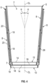
Fig. 4 is a schematic cross-sectional view of a pair of containers, each as shown inFig. 1 , in a nested configuration. - Corresponding parts are designated by corresponding reference numbers throughout the drawings.
- Containers according to the present disclosure can accommodate fluids, e.g., beverages, of different sizes and compositions. For the purpose of illustration and not for the purpose of limiting the scope of the disclosure, the following detailed description describes a container for heated fluids, e.g., coffee or coffee-based products, tea, hot chocolate, cider, soup, etc. It will be understood that the containers described herein can hold cold beverages or room temperature beverages, and can hold at least partially solid food products, without departing from the disclosure.
- In this specification, the terms "lower," "bottom," "upper," and "top" indicate orientations determined in relation to fully erected and upright containers. As described herein, containers can be formed from blanks by overlapping multiple portions, panels, and/or end flaps. Such portions, panels, and/or end flaps may be designated herein in terms relative to one another, e.g., "first", "second", "third", etc., in sequential or non-sequential reference, without departing from the disclosure.
-
Fig. 1 is a perspective view, andFig. 2 is a schematic cross-sectional view, of a fluid vessel orfluid container 5 according to a first exemplary embodiment of the disclosure. In one embodiment, thecontainer 5 is a cup having the general shape of a truncated cone, with anopen top 6, a closedbottom 13, and asidewall construct 8 extending from a bottom edge to a top edge of thecontainer 5. The closedbottom 13 and thesidewall construct 8 define aninterior space 7 of thecontainer 5 that is for holding fluids, e.g. hot beverages such as tea, coffee, cider, hot chocolate, etc. - In the illustrated embodiment, the
sidewall construct 8 comprises an annular inner sidewall 19 (broadly, "inner wall") and an outer sleeve 23 (broadly, "outer wall") attached to theinner sidewall 19 such that thesidewall construct 8 can be referred to as a double wall structure. As described herein, thecontainer 5 includes insulating features in thesidewall construct 8 that include radiallyadjacent spacers 29 separated by respectiveradial gaps 31. Thespacers 29 can be at least partially formed from an adhesive, such as a hot melt glue or other glue, and can extend from theinner sidewall 19 to theouter sleeve 23 to adhesively attach theouter sleeve 23 to theinner sidewall 19. In one embodiment, thespacers 29 can be formed from a different polymeric material. - As discussed further herein, the insulating features of the
container 5 are arranged such that cost and materials savings can be realized, and so that an insulation profile of thecontainer 5 can be selected so as to be enhanced, for example, so that the fluid in thecontainer 5 can be maintained at a selected or desired temperature or temperature range, and such that a customer can be provided with a more comfortable surface about which to grasp thecontainer 5. - As shown in
Fig. 2 , thebottom 13 of thecontainer 5 includes a generallycircular bottom panel 14 and anannular leg 15 foldably connected to and downwardly-depending from thebottom panel 14 at a circular line of weakening 17. The annularinner sidewall 19 extends upwardly from thebottom panel 14 to define theinterior 7 of thecontainer 5. As also shown, theinner sidewall 19 extends downwardly below thebottom panel 14 to define alower edge margin 20 thereof, along a portion of which theannular leg 15 is adhesively attached to secure thebottom panel 14 to theinner sidewall 19 and to form thebottom 13 of theinterior 7 of thecontainer 5. - As shown, the
lower edge margin 20 of theinner sidewall 19 extends along the outer surface of theannular leg 15, wraps under a bottom edge or lower edge thereof, and extends upwardly along the interior surface of theannular leg 15 toward thebottom panel 14. Thelower edge margin 20 of theinner sidewall 19 can be an at least partially flexible portion of theinner sidewall 19 configured to engage theannular leg 15, and can include surface features to facilitate such engagement, for example, an adhesive treatment and/or frictionally-enhancing patterning. As described herein, the portion of thelower edge margin 20 of theinner sidewall 19 overlying the lower edge of theannular leg 15 will define a bottom edge orlower edge 18 of theinner sidewall 19. In one embodiment, the lower edge of theannular leg 15 can define the lower edge of the coupledinner sidewall 19 and thebottom 13. Thebottom 13 can be secured to thesidewall construct 8 in a different configuration without departing from the disclosure. - As shown, an upper portion of the
inner sidewall 19 is curved or curled to define a top orupper rim 21 of thecontainer 5 that circumscribes anopening 22 in communication with theinterior 7 of thecontainer 5. Therim 21 and/or an upper portion of thecontainer 5 can be flanged or otherwise configured to engage a lid or other top container closure structure. - In one embodiment, the bottom 13 of the
container 5 can be integrally formed with theinner sidewall 19, e.g., such that theannular leg 15 is integrally formed with theinner sidewall 19, or the bottom 13 can be otherwise attached to a portion of theinner sidewall 19 by other attachment means, for example, crimping, heat sealing, etc. - In one embodiment, the illustrated configuration of the truncated conical shape of the
container 5 can be achieved by forming theinner sidewall 19 from a flat blank that is folded around a mandrel such that an overlapping seam is provided, and which can be secured, for example, with an adhesive such as glue. The generally truncated conical shape of thesleeve 23 can be formed in a similar manner, or can be formed through a different process without departing from the disclosure. - The arrangement of the
bottom panel 14 and theannular leg 15 of theclosed bottom 13 of thecontainer 5 can be formed, in one example, by providing a generally circular blank having an outer periphery that is downwardly folded to provide theannular leg 15 that intersects thebottom panel 14 at the line ofweakening 17. It will be understood that thecontainer 5 can have a different configuration and can be formed by other methods and mechanisms without departing from the disclosure. - Still referring to
Figs. 1 and2 , the outer sleeve orsleeve 23, e.g., a wrap or other layer, is disposed in at least partial circumferential engagement with theinner sidewall 19 such that thesleeve 23 presents an outer surface of thecontainer 5 for engagement by a customer, e.g., such that the customer can wrap his or her fingers around a portion of thesleeve 23. Thesleeve 23 can be formed, for example, from materials that include single layer structures, multi-layer structures (with or without inserts therebetween), corrugated materials, etc. - As shown, the
sleeve 23 includes anupper edge 25 proximate therim 21 and alower edge 27 proximate the lower portion of theinner sidewall 19 generally adjacent the bottom 13. As described herein, at least the interface between thesleeve 23 and theinner sidewall 19 provide insulating features of thecontainer 5 that include acavity 24 defined between theinner sidewall 19 and theouter sleeve 23. The insulating features of thecontainer 5 can also include one or more portions of theinner sidewall 19 and/or thesleeve 23. - Referring additionally to
Fig. 3 , a front view of thecontainer 5 with thesleeve 23 removed is illustrated. As shown, a plurality of annular bands B1, B2, B3, B4, B5, B6, and B7 of adhesive are applied around the circumference of theinner sidewall 19 and are positioned between theinner sidewall 19 and theouter sleeve 23 to attach theouter sleeve 23 to theinner sidewall 19 and to form thespacers 29. One or more of the annular bands B1, B2, B3, B4, B5, B6, and B7 can be a discontinuous pattern of adhesive such that the bands comprise adhesive that form thespacers 29 that each extend from theinner sidewall 19 to theouter sleeve 23, and thegaps 31 are radially spaced betweenadjacent spacers 29 along the circumferential length of each of the respective bands around theinner sidewall 19. In one embodiment, thegaps 31 are sections of each respective band that can be voids, interruptions, or discontinuities of the material that forms thespacers 29 along the bands B1, B2, B3, B4, B5, B6, and B7. It will be understood that a different numbers of bands ofspacers 29 can be provided without departing from the disclosure. - The
spacers 29, as shown, can be elongate members, for example, beads, dots, dashes, tracks, trails, and/or other arrangements of material. Thespacers 29 can be formed of a composite material or polymeric material, such as a hot melt adhesive or other type of adhesive or glue, though thespacers 29 could be material other than adhesive and theouter sleeve 23 could be attached to theinner wall 19 by means other than the annular bands without departing from the disclosure. - In the illustrated embodiment, the
spacers 29 can provide and/or maintain spacing between theinner sidewall 19 and thesleeve 23, and can additionally provide an attachment, e.g., adhesion, between theinner sidewall 19 and thesleeve 23. As shown, thespacers 29 have a length L1 corresponding to the length of an arc around the circumference of the portion of theinner sidewall 19 covered by thespacer 29, with the length L1 extending between respective first andsecond ends spacer 29. Similarly, thegaps 31 have a length L2 corresponding to the length of an arc around the circumference of the portion of theinner sidewall 19 corresponding to the location of the gap that is a portion of the corresponding band that is void of the material that forms thespacers 29, with the length L2 extending from asecond end 29b to afirst end 29a ofadjacent spacers 29. In one embodiment, the length L1 can be greater than the length L2. In another embodiment, the length L2 can be greater than the length L1. - The sum of the lengths L2 of
respective gaps 31 of a respective annular band ofspacers 29 can correspond to a materials savings of the respective annular band, and by extension, thecontainer 5. Such material savings can be represented as a percentage of the material of a comparative annular band having a continuous spacer (i.e., with substantially no gaps therealong), for example, between about 20% and about 80% of such material, such as 20%, 25%, 30%, 35%, 40%, 45%, 50%, 55%, 60%, 65%, 70%, 75%, 80%, or other integer or non-integer numbers therebetween. Accordingly, the materials savings of theentire container 5 can be determined by the summation of the material corresponding to the respective lengths L2 of allgaps 31 in the annular bands B1, B2, B3, B4, B5, B6, B7, and can represented as a percentage of material of a summed comparative set of annular bands having respective continuous spacers as described above. - While the
spacers 29 and thegaps 31 have been shown as having a generally uniform configuration along thecontainer 5, it will be understood that one ormore spacers 29 and/orgaps 31 can have a different configuration without departing from the disclosure. - Still referring to
Figs. 1-3 , thespacers 29 and thegaps 31 of the bands B1, B2, B3, B4, B5, B6, B7 are arranged along theinner sidewall 19 such that a plurality of fluid pathways F1, F2 are presented around thespacers 29 and throughrespective gaps 31 between theupper edge 25 of thesleeve 23 and thelower edge 27 of the sleeve 23 (shown with broken lines inFig. 3 for reference). While two fluid pathways F1, F2 are illustrated, the configuration of the annular bands B1, B2, B3, B4, B5, B6, B7 provide much more than two possible fluid pathways. The configuration of the fluid pathways F1, F2 can be at least partially defined by the arrangement and relative offset ofspacers 29 andgaps 31 in adjacent bands B1, B2, B3, B4, B5, B6, B7, which can be uniform or non-uniform, such that the fluid pathways F1, F2 can have a substantially linear (e.g., vertical or oblique) or curved configuration. As shown, vertically-adjacent gaps 31 are generally offset from one another, though verticallyadjacent gaps 31 in one or more of the bands B1, B2, B3, B4, B5, B6, B7 can be aligned without departing from the disclosure. In one embodiment, the fluid pathways F1, F2 can follow a substantially torturous or serpentine path. It will be understood that the fluid pathways F1, F2 can be defined aroundspacers 29 throughgaps 31 that are not necessarily adjacent, e.g., such that fluid pathways F1, F2 can extend at least partially around theinner sidewall 19 between one or more of bands B1, B2, B3, B4, B5, B6, B7 before traveling through a vertically-adjacent gap 31 without departing from the disclosure. - According to the invention, the configuration of the bands B1, B2, B3, B4, B5, B6, B7 that create the tortious pathways F1, F2 help create resistance to air flow from the
cavity 24 between the inner sidewall 9 and theouter sleeve 23, to the environment outside thecavity 24 which helps maintain the temperature of the beverage in the container by reducing the amount of heat transfer from thecavity 24 to the atmosphere E (Fig. 2 ). - As shown in
Fig. 2 , a pocket P1 is formed in thecavity 24 between theinner sidewall 19 and thesleeve 23 between the band B1 and the band B2, a pocket P2 is formed in thecavity 24 between theinner sidewall 19 and thesleeve 23 between the band B2 and the band B3, a pocket P3 is formed in thecavity 24 between theinner sidewall 19 and thesleeve 23 between the band B3 and the band B4, a pocket P4 is formed in thecavity 24 between theinner sidewall 19 and thesleeve 23 between the band B4 and the band B5, a pocket P5 is formed in thecavity 24 between theinner sidewall 19 and thesleeve 23 between the band B5 and the band B6, and a pocket P6 is formed in thecavity 24 between theinner sidewall 19 and thesleeve 23 between the band B6 and the band B7. At least the pockets P1, P2, P3, P4, P5, P6 provide insulating gaps or spaces between theinner sidewall 19 and thesleeve 23. - In one embodiment, each pocket P1, P2, P3, P4, P5, P6 can have a width measured from the
inner sidewall 19 to thesleeve 23 and at least partially determined by the size of thespacers 29, which also have such width between about 0,76 mm (30 mils) and about 0,97 mm (38 mi1s). - The arrangement of the
spacers 29 and thegaps 31 along theinner sidewall 19 is such that thegaps 31 provides for fluid communication/air flow between the respective pockets at various locations along thecontainer 5. In one embodiment, the fluid pathways F1, F2 comprise one or more of the respective pockets P1, P2, P3, P4, P5, P6. - In this regard, the arrangement of the
spacers 29 and thegaps 31 of the annular bands B1, B2, B3, B4, B5, B6, B7 provide the one or more fluid pathways. The disclosed arrangement of insulating features is such that heat H generated or held by a fluid in theinterior 7 of thecontainer 5 can transfer, for example, through conduction, convection, and/or radiation, through theinner sidewall 19 and/orspacers 29 into one or more of the pockets P1, P2, P3, P4, P5, P6, and can be released into the external environment E via the one or more fluid pathways, e.g., F1, F2. Such insulating features can maintain the temperature of the fluid inside thecontainer 5 by resisting heat transfer from thecavity 24 between theinner sidewall 19 and thesleeve 23 to the atmosphere E while still maintaining a desired surface temperature of thesleeve 23 to facilitate grasping by a customer. - Further, in one embodiment, the surface temperature of the
sleeve 23 can be higher at points along thesleeve 23 that are aligned with thespacers 29, for example, due to thermal conduction of heat H through the solid material of thespacers 29, i.e., such that thespacers 29 are formed of a thermally-conductive material. Accordingly, regions of thesleeve 23 aligned with thegaps 31 and/or the pockets P1, P2, P3, P4, P5, P6 present surface regions of lower temperature at which a user can grasp thesleeve 23, for example, by shifting the placement of his or her fingers along thesleeve 23 to provide for more comfortable use of thecontainer 5. In this regard, the dimensioning and arrangement of thespacers 29 and thegaps 31 can be selected to provide a desired thermal profile along the outer surface of thesleeve 23 when thecontainer 5 is filled with a hot fluid such as tea, coffee, cider, hot chocolate, etc. In one embodiment, the fluid in thecontainer 5 can have a temperature up to, including, or greater than about 88° C (190° F). - The aforementioned reduction in material for forming the annular bands B1, B2, B3, B4, B5, B6, B7 of
spacers 29 withgaps 31 can provide material and cost-saving benefits as compared to annular bands of continuous spacers with no gaps, e.g., by reducing the cost and materials required to form thecontainer 5, and can also provide streamlining in product production and waste management. In addition to or in the alternative, the relative configuration of thespacers 29 and thegaps 31 can impart desired structural properties to thecontainer 5, for example, by providing a desired pattern of rigidity such that an optimal pattern of flexion is provided to thecontainer 5 during use. For example, upon grasping of thesidewall construct 8 by a customer, portions of thesleeve 23/inner sidewall 19 can bend or flex inwardly into one or more of thegaps 31 or pockets P1, P2, P3, P4, P5, P6 to provide a textured or irregular surface configuration to enhance the customer's grip on thecontainer 5. In one embodiment, the rigidity of thecontainer 5 can be between about 1.30 kgf and about 2.30 kgf, for example, 1.30 kgf, 1.40 kgf, 1.50 kgf, 1.60 kgf, 1.70 kgf, 1.80 kgf, 1.90 kgf, 2.0 kgf, 2.1 kgf, 2.2 kgf, 2.3 kgf, or other integer or non-integer values therebetween, with the rigidity being the amount of force applied to thecontainer 5 to cause bending or flexing of thesidewall construct 8. - In addition to the insulative and materials-saving properties of the
container 5 described above, thecontainer 5 is further provided with a configuration that can realize significant space savings, for example, during storage and transport. Referring additionally toFig. 4 , the inner sidewall 19 (and thesleeve 23 disposed therearound) of thecontainer 5, as shown, have a tapered configuration such that theinner sidewall 19 and thesleeve 23 extend at an α relative to a vertical centerline CL of thecontainer 5. The arrangement of theinner sidewall 19, thesleeve 23, and the bottom 13 can be such that, upon nesting ofmultiple containers 5, e.g., such that acontainer 5 is at least partially disposed in theinterior space 7 of arespective container 5 below, thebottom edge 18 of theinner sidewall 19 of theupper container 5 contacts thebottom panel 14 of thelower container 5 before the respective sidewall constructs 8 substantially frictionally engage one another. In this regard, uncoupling of the nestedcontainers 5 is not substantially inhibited by frictional resistance. Accordingly, such a nested arrangement ofcontainers 5 provides significant space savings for the transport and/or storage ofmultiple containers 5 because theinterior 7 of arespective container 5 can be utilized to at least partially receive thesidewall construct 8 and bottom 13 of a vertically-adjacent container 5. It will be understood that thecontainer 5 can have a different configuration and can be formed by other methods and mechanisms without departing from the disclosure. - The containers and/or the blanks that form the containers according to the present disclosure can be, for example, formed from coated paperboard and similar materials. For example, the interior and/or exterior sides of the blanks can be coated with a clay coating. The clay coating may then be printed over with product, advertising, price coding, and other information or images. The blanks may then be coated with a varnish to protect any information printed on the blank. The blanks may also be coated with, for example, a moisture barrier layer, on either or both sides of the blank. In accordance with the above-described embodiments, the blanks may be constructed of paperboard of a caliper such that it is heavier and more rigid than ordinary paper. The blanks can also be constructed of other materials, such as cardboard, hard paper, or any other material having properties suitable for enabling the container to function at least generally as described herein. The blanks can also be laminated or coated with one or more sheet-like materials at selected panels or panel sections.
- In accordance with the above-described embodiments of the present disclosure, a fold line can be any substantially linear, although not necessarily straight, form of weakening that facilitates folding there along. More specifically, but not for the purpose of narrowing the scope of the present disclosure, fold lines include: a score line, such as lines formed with a blunt scoring knife, or the like, which creates a crushed portion in the material along the desired line of weakness; a cut that extends partially into a material along the desired line of weakness, and/or a series of cuts that extend partially into and/or completely through the material along the desired line of weakness; and various combinations of these features.
- The above embodiments may be described as having one or more portions adhered together by glue during erection of the container embodiments. The term "glue" is intended to encompass all manner of adhesives commonly used to secure containers in place.
Claims (17)
- A container (5) for containing a fluid, comprising:a sidewall construct (8) comprising an inner sidewall (19) extending at least partially around an interior (7) of the container (5), an outer sleeve (23) attached to the inner sidewall (19), and a cavity (24) defined between the inner sidewall (19) and the outer sleeve (23); anda closed bottom (13) defining a bottom of the interior (7) of the container (5),the container (5) comprises insulating features comprising the cavity (24) and a plurality of annular bands (B1, B2, B3, B4, B5, B6, B7), each annular band of the plurality of annular bands (B1, B2, B3, B4, B5, B6, B7) comprises a plurality of spacers (29) and a plurality of gaps (31) separating respective adjacent spacers (29) in a respective annular band, each spacer extends in the cavity (24) from the inner sidewall (19) to the outer sleeve (23) and one or more of the spacers having a width between about 0,76 mm (30 mils) and about 0,97 mm (38 mils),the gaps (31) of the respective annular bands define a plurality of fluid paths (F1, F2) through the cavity (24), the respective gaps (31) of respective adjacent annular bands are offset from one another, at least one fluid path of the plurality of fluid paths (F1, F2) extends from a lower edge (27) of the outer sleeve (23) to an upper edge (25) of the outer sleeve (23), the cavity is open to an external environment at each of the upper edge of the outer sleeve and the lower edge of the outer sleeve such that the at least one fluid path of the plurality of fluid paths is in communication with the external environment.
- The container (5) of claim 1, wherein a respective plurality of pockets (P1, P2, P3, P4, P5, P6) are defined between respective adjacent annular bands,
the plurality of pockets (P1, P2, P3, P4, P5, P6) provide a respective plurality of insulating spaces between the inner sidewall (19) and the outer sleeve (23). - The container (5) of claim 1, wherein each respective annular band of the plurality of annular bands (B1, B2, B3, B4, B5, B6, B7) extends around the circumference of the inner sidewall (19) and is discontinuous in that the gaps (31) comprise sections of each annular band that is void of material that forms the spacers (29).
- The container (5) of claim 1, wherein the plurality of spacers (29) comprises a polymeric material that is an adhesive that adheres the outer sleeve (23) to the inner sidewall (19), the adhesive is a thermally conductive material.
- The container (5) of claim 1, wherein the closed bottom (13) comprises a bottom panel (14) and an annular leg (15) foldably connected to the bottom panel (14),
the annular leg (15) extends downwardly from the bottom panel (14), the annular leg (15) is attached to a lower edge margin of the inner sidewall (19). - The container (5) of claim 1, wherein an upper portion of the inner sidewall (19) defines a flanged rim (21), the rim (21) is configured to interengage a container closure.
- A sidewall construct (8) for forming a fluid container (5), the sidewall construct (8) comprising:an inner sidewall (19) for extending at least partially around an interior of a fluid container (5) formed from the sidewall construct (8);an outer sleeve (23) attached to the inner sidewall (19);a cavity (24) defined between the inner sidewall (19) and the outer sleeve (23); andinsulating features comprising the cavity (24) and a plurality of annular bands (B1, B2, B3, B4, B5, B6, B7), each annular band of the plurality of annular bands (B1, B2, B3, B4, B5, B6, B7) comprises a plurality of spacers (29) and a plurality of gaps (31) separating respective adjacent spacers (29) in a respective annular band, each spacer extends in the cavity (24) from the inner sidewall (19) to the outer sleeve (23) and one or more of the spacers having a width between about 0,76 mm (30 mils) and about 0,97 mm (38 mils),the gaps (31) of the respective annular bands define a plurality of fluid paths (F1, F2) through the cavity (24), the respective gaps (31) of respective adjacent annular bands are offset from one another, at least one fluid path of the plurality of fluid paths (F1, F2) extends from a lower edge (27) of the outer sleeve (23) to an upper edge (25) of the outer sleeve (23) ), the cavity is open to an external environment at each of the upper edge of the outer sleeve and the lower edge of the outer sleeve such that the at least one fluid path of the plurality of fluid paths is in communication with the external environment.
- The sidewall construct (8) of claim 7, wherein a respective plurality of pockets (P1, P2, P3, P4, P5, P6) are defined between respective adjacent annular bands,
the plurality of pockets (P1, P2, P3, P4, P5, P6) provide a respective plurality of insulating spaces between the inner sidewall (19) and the outer sleeve (23). - The sidewall construct (8) of claim 7, wherein each respective annular band of the plurality of annular bands (B1, B2, B3, B4, B5, B6, B7) extends around the circumference of the inner sidewall (19) and is discontinuous in that the gaps (31) comprise sections of each annular band that is void of material that forms the spacers (29).
- The sidewall construct (8) of claim 7, wherein the plurality of spacers (29) comprises a polymeric material that is an adhesive that adheres the outer sleeve (23) to the inner sidewall (19), the adhesive is a thermally conductive material.
- The sidewall construct (8) of claim 7, wherein an upper portion of the inner sidewall (19) defines a flanged rim (21), the rim (21) is configured to interengage a container closure.
- A method of forming a container (5) for containing a fluid, comprising;obtaining an inner sidewall (19) and an outer sleeve (23); attaching the outer sleeve (23) to the inner sidewall (19) to form a sidewall construct (8) with a cavity (24) defined between the inner sidewall (19) and the outer sleeve (23), the attaching comprises forming insulating features in the sidewall construct (8), the insulating features comprise the cavity (24) and a plurality of annular bands (B1, B2, B3, B4, B5, B6, B7), each annular band of the plurality of annular bands (B1, B2, B3, B4, B5, B6, B7) comprises a plurality of spacers (29) and a plurality of gaps (31) separating respective adjacent spacers (29) in a respective annular band, each spacer extends in the cavity (24) from the inner sidewall (19) to the outer sleeve (23) and one or more of the spacers having a width between about 0,76 mm (30 mils) and about 0,97 mm (38 mils),the gaps (31) of the respective annular bands define a plurality of fluid paths (F1, F2) through the cavity (24), the respective gaps (31) of respective adjacent annular bands are offset from one another, at least one fluid path of the plurality of fluid paths (F1, F2) extends from a lower edge (27) of the outer sleeve (23) to an upper edge (25) of the outer sleeve (23) and the cavity is open to an external environment at each of the upper edge of the outer sleeve and the lower edge of the outer sleeve such that the at least one fluid path of the plurality of fluid paths is in communication with the external environment;forming an interior of the fluid container (5) by positioning the sidewall construct (8) so that the inner sidewall (19) extends at least partially around the interior; andpositioning a closed bottom (13) relative to the sidewall construct (8) to define a bottom of the interior.
- The method of claim 12, wherein a respective plurality of pockets (P1, P2, P3, P4, P5, P6) are defined between respective adjacent annular bands,
the plurality of pockets (P1, P2, P3, P4, P5, P6) provide a respective plurality of insulating spaces between the inner sidewall (19) and the outer sleeve (23). - The method of claim 12, wherein each respective annular band of the plurality of annular bands (B1, B2, B3, B4, B5, B6, B7) extends around the circumference of the inner sidewall (19) and is discontinuous in that the gaps (31) comprise sections of each annular band that is void of material that forms the spacers (29).
- The method of claim 12, wherein the plurality of spacers (29) comprises a polymeric material that is an adhesive that adheres the outer sleeve (23) to the inner sidewall (19), the adhesive is a thermally conductive material.
- The method of claim 12, wherein the closed bottom (13) comprises a bottom panel (14) and an annular leg (15) foldably connected to the bottom panel (14),
the annular leg (15) extends downwardly from the bottom panel (14), the annular leg (15) is attached to a lower edge margin of the inner sidewall (19). - The method of claim 12, wherein an upper portion of the inner sidewall (19) defines a flanged rim (21), the rim (21) is configured to interengage a container closure.
Applications Claiming Priority (4)
| Application Number | Priority Date | Filing Date | Title |
|---|---|---|---|
| US201862657246P | 2018-04-13 | 2018-04-13 | |
| US201862674834P | 2018-05-22 | 2018-05-22 | |
| US201962794131P | 2019-01-18 | 2019-01-18 | |
| PCT/US2019/027119 WO2019200188A1 (en) | 2018-04-13 | 2019-04-12 | Container with insulating features |
Publications (4)
| Publication Number | Publication Date |
|---|---|
| EP3774584A1 EP3774584A1 (en) | 2021-02-17 |
| EP3774584A4 EP3774584A4 (en) | 2022-02-16 |
| EP3774584C0 EP3774584C0 (en) | 2025-06-25 |
| EP3774584B1 true EP3774584B1 (en) | 2025-06-25 |
Family
ID=68160695
Family Applications (3)
| Application Number | Title | Priority Date | Filing Date |
|---|---|---|---|
| EP19785699.0A Pending EP3774586A4 (en) | 2018-04-13 | 2019-04-12 | CONTAINER WITH INSULATING ELEMENTS |
| EP19784621.5A Active EP3774584B1 (en) | 2018-04-13 | 2019-04-12 | Container with insulating features |
| EP19785215.5A Pending EP3774585A4 (en) | 2018-04-13 | 2019-04-12 | CONTAINER EQUIPPED WITH EVOLVING ELEMENTS |
Family Applications Before (1)
| Application Number | Title | Priority Date | Filing Date |
|---|---|---|---|
| EP19785699.0A Pending EP3774586A4 (en) | 2018-04-13 | 2019-04-12 | CONTAINER WITH INSULATING ELEMENTS |
Family Applications After (1)
| Application Number | Title | Priority Date | Filing Date |
|---|---|---|---|
| EP19785215.5A Pending EP3774585A4 (en) | 2018-04-13 | 2019-04-12 | CONTAINER EQUIPPED WITH EVOLVING ELEMENTS |
Country Status (7)
| Country | Link |
|---|---|
| US (3) | US20190315555A1 (en) |
| EP (3) | EP3774586A4 (en) |
| CA (3) | CA3095800C (en) |
| ES (1) | ES3035822T3 (en) |
| MX (3) | MX2020010730A (en) |
| PL (1) | PL3774584T3 (en) |
| WO (3) | WO2019200186A1 (en) |
Families Citing this family (3)
| Publication number | Priority date | Publication date | Assignee | Title |
|---|---|---|---|---|
| US12291003B2 (en) | 2018-04-13 | 2025-05-06 | Graphic Packaging International, Llc | Method and system for forming a container with insulating features |
| US11760529B2 (en) | 2019-04-05 | 2023-09-19 | Huhtamaki, Inc. | Container and bottom end construction therefor |
| WO2023205117A1 (en) * | 2022-04-19 | 2023-10-26 | Graphic Packaging International, Llc | A method and system for forming a container with insulating features |
Citations (1)
| Publication number | Priority date | Publication date | Assignee | Title |
|---|---|---|---|---|
| US20180016052A1 (en) * | 2015-02-25 | 2018-01-18 | Dai Nippon Printing Co., Ltd. | Double container and exterior sleeve used in double container |
Family Cites Families (104)
| Publication number | Priority date | Publication date | Assignee | Title |
|---|---|---|---|---|
| US21955A (en) | 1858-11-02 | Louis grosholz | ||
| US1771765A (en) | 1925-01-24 | 1930-07-29 | Kalix Cup Company | Waterproof paper receptacle |
| US2266828A (en) | 1939-01-05 | 1941-12-23 | Milwaukee Lace Paper Company | Paper cup |
| US2675954A (en) | 1952-03-03 | 1954-04-20 | Frank W Vogel | Drinking cup |
| US3208631A (en) | 1957-11-29 | 1965-09-28 | Illinois Tool Works | Nestable cup |
| USRE25618E (en) | 1959-07-21 | 1964-07-14 | Figure | |
| US3079027A (en) | 1959-12-10 | 1963-02-26 | Illinois Tool Works | Double walled nestable plastic container |
| US3169689A (en) | 1963-05-13 | 1965-02-16 | Traders Leasing Ltd | Thin walled container |
| GB1261532A (en) | 1968-01-04 | 1972-01-26 | Mono Containers Ltd | Double walled drinking cup |
| US3456860A (en) | 1968-01-09 | 1969-07-22 | Illinois Tool Works | Double wall cup |
| US3526316A (en) | 1968-08-08 | 1970-09-01 | Theodore P Kalogris | Hydratable substance-containing single service drinking receptacle |
| US3580468A (en) | 1969-08-05 | 1971-05-25 | Continental Can Co | Nestable double-walled disposable container |
| DE2003011C3 (en) | 1970-01-23 | 1974-05-16 | Gustav Konig | Precast slab connection |
| US4007670A (en) | 1974-02-28 | 1977-02-15 | St. Regis Paper Company | Insulated container |
| US4049122A (en) | 1974-10-21 | 1977-09-20 | Maxwell Earl G | Nestable non-corrosive container for pressurized beverages and processes for manufacture and handling thereof |
| US4231476A (en) | 1979-07-02 | 1980-11-04 | Mars Limited | Plastics containers |
| US4261501A (en) | 1979-10-31 | 1981-04-14 | Hallmark Cards Incorporated | Laminated insulated hot drink cup |
| JPS57110439A (en) | 1980-12-29 | 1982-07-09 | Nihon Dixie Co Ltd | Vessel made of heat insulating paper and its manufacture |
| US5226585A (en) | 1991-11-19 | 1993-07-13 | Sherwood Tool, Inc. | Disposable biodegradable insulated container and method for making |
| US5145107A (en) | 1991-12-10 | 1992-09-08 | International Paper Company | Insulated paper cup |
| US5205473A (en) | 1992-03-19 | 1993-04-27 | Design By Us Company | Recyclable corrugated beverage container and holder |
| DE4226313A1 (en) | 1992-08-08 | 1994-02-10 | Eger Albert Gmbh & Co | Method and device for producing cardboard sleeves which are closed on one side and are essentially cylindrical |
| US5326019A (en) | 1993-05-03 | 1994-07-05 | Wolff Steven K | Double walled paper cup |
| JP3054989B2 (en) | 1993-06-19 | 2000-06-19 | 八幡 貞男 | Insulated expression container |
| US5425497A (en) | 1993-11-09 | 1995-06-20 | Sorensen; Jay | Cup holder |
| US5769311A (en) | 1994-08-02 | 1998-06-23 | Toppan Printing Co., Ltd. | Heat insulating cup and method of manufacturing the same |
| US5460323A (en) | 1995-01-10 | 1995-10-24 | California Environmental Cup, Inc. | Disposable insulated container |
| JPH08276927A (en) | 1995-03-31 | 1996-10-22 | Toppan Printing Co Ltd | Insulated cup container |
| US5524817A (en) | 1995-04-04 | 1996-06-11 | Paper Machinery Corporation | Dual walled container |
| TR199701246T1 (en) | 1995-04-24 | 1998-03-21 | The Procter&Gamble Company | A product of disposable paper with a marker tool. |
| US5547124A (en) | 1995-07-18 | 1996-08-20 | Michael Hoerauf Maschinenfabrik Gmbh & Co. Kg | Heat insulating container |
| US5542599A (en) | 1995-08-07 | 1996-08-06 | Sobol; Ronald E. | Biodegradable thermally insulated beverage cup |
| US5660326A (en) | 1995-08-18 | 1997-08-26 | Sherwood Tool Incorporated | Multi-layered insulated cup formed from folded sheet |
| US5628453A (en) | 1996-01-16 | 1997-05-13 | Packaging Resources, Inc. | Cup with thermally insulated side wall |
| US5826786A (en) | 1996-03-06 | 1998-10-27 | Dickert; James | Cup holder sleeve in pre-assembled flat-folded form |
| US5772111A (en) | 1996-03-12 | 1998-06-30 | Kirsch; John M. | Container structure |
| GB9606288D0 (en) | 1996-03-26 | 1996-05-29 | Ivex Corp | Sleeve for beverage cups |
| US5667135A (en) | 1996-04-17 | 1997-09-16 | Sweetheart Cup Company, Inc. | Thermal insulating sleeve for drink cups |
| US5752653A (en) * | 1996-05-13 | 1998-05-19 | Razzaghi; Mahmoud | Paper cup with air insulation |
| US6265040B1 (en) | 1996-06-14 | 2001-07-24 | Insulation Dimension Corporation | Self-bonding syntactic foam insulated container sleeve |
| US5952068A (en) | 1996-06-14 | 1999-09-14 | Insulation Dimension Corporation | Syntactic foam insulated container |
| US5839653A (en) | 1996-07-12 | 1998-11-24 | Zadravetz; Robert B. | Container with corrugated wall |
| US5685480A (en) | 1996-08-16 | 1997-11-11 | Choi; Danny K. | Insulated drinking cup |
| US5713512A (en) | 1996-09-03 | 1998-02-03 | Polytainers, Inc. | Polymeric insulated container |
| US5775577A (en) | 1996-10-15 | 1998-07-07 | Baldocci, Modena, Scherrer, Stanghellini Family Trust, And Titus | Disposable insulated container with microflute structure |
| US5794843A (en) | 1996-11-08 | 1998-08-18 | Sanchez; Rafael S. | Cup wrap |
| US5746372A (en) | 1996-12-12 | 1998-05-05 | American Excelsior Company | Biodegradable cup holder |
| US6416829B2 (en) | 1997-06-06 | 2002-07-09 | Fort James Corporation | Heat insulating paper cups |
| US5950917A (en) | 1997-07-14 | 1999-09-14 | Sealright Co., Inc. | Dual wall insulated container and method for making the same |
| CN100396478C (en) | 1997-08-28 | 2008-06-25 | 大日本印刷株式会社 | Rib processing device |
| JPH11157525A (en) | 1997-11-27 | 1999-06-15 | Keiichi Tokunaga | Container |
| US5975336A (en) | 1998-02-13 | 1999-11-02 | Hart; David Alan | Containing device with removable thermal insulating layer |
| KR100829673B1 (en) | 1998-05-20 | 2008-05-19 | 다이니폰 인사츠 가부시키가이샤 | Insulating container |
| DE19840841B4 (en) | 1998-09-07 | 2007-02-08 | Michael Hörauf Maschinenfabrik GmbH & Co. KG | Heat-insulating mug |
| JP4097807B2 (en) | 1998-10-19 | 2008-06-11 | 大日本印刷株式会社 | Heat insulating container |
| JP2000142834A (en) | 1998-11-04 | 2000-05-23 | Tokan Kogyo Co Ltd | Simple container |
| US6085970A (en) | 1998-11-30 | 2000-07-11 | Insulair, Inc. | Insulated cup and method of manufacture |
| JP2000226022A (en) | 1999-02-04 | 2000-08-15 | Tokan Kogyo Co Ltd | Simple container |
| US6152363A (en) | 1999-05-03 | 2000-11-28 | Westvaco Corporation | Sleeve construction for improved paperboard cup insulation |
| US6253995B1 (en) | 2000-05-16 | 2001-07-03 | Burrows Paper Corporation | Insulated containers and sidewalls having laterally extending flutes, and methods |
| CA2309621A1 (en) | 2000-06-29 | 2001-12-29 | Paul A. Taylor | Cup-holder napkin |
| ES2222327T3 (en) | 2001-01-30 | 2005-02-01 | Seda S.P.A. | DOUBLE WALL CONTAINER. |
| DE60102661T2 (en) | 2001-01-30 | 2004-08-19 | Seda S.P.A. | Cardboard containers for beverages and processes therefor |
| US20020179617A1 (en) | 2001-05-31 | 2002-12-05 | Landra Barthlow | Wrap-around for a beverage container |
| US7614993B2 (en) | 2001-07-20 | 2009-11-10 | Dixie Consumer Products Llc | Liquid container with uninterrupted comfort band and method of forming same |
| US6598786B1 (en) | 2002-03-05 | 2003-07-29 | Tzer-Huang Guo | Melioration of insulating paper container |
| US6926197B2 (en) | 2002-12-12 | 2005-08-09 | Aharon Zeev Hed | Disposable and biodegradable paper cup |
| US7537136B2 (en) | 2003-06-11 | 2009-05-26 | Laurent Hechmati | Foldable air insulating sleeve |
| US20050184137A1 (en) * | 2004-01-02 | 2005-08-25 | Dorsey Massai Z. | Bullhorn cup |
| US20050236468A1 (en) | 2004-04-22 | 2005-10-27 | Insulair, Inc. | Insulating cup wrapper and insulated container formed with wrapper |
| US7281649B2 (en) * | 2004-11-19 | 2007-10-16 | Solo Cup Operating Corporation | Bottom seal for container |
| DE102004056932B4 (en) * | 2004-11-22 | 2022-07-28 | Ptm Packaging Tools Machinery Pte. Ltd. | Double wall paper cup and method of making a double wall paper cup |
| BRPI0601188B1 (en) | 2005-04-15 | 2018-06-26 | Seda S.P.A. | ISOLATED CONTAINER; METHOD OF MANUFACTURING THE SAME AND APPARATUS FOR MANUFACTURING |
| DE102005030310B3 (en) | 2005-06-23 | 2006-12-21 | Fraunhofer-Gesellschaft zur Förderung der angewandten Forschung e.V. | Thermal insulating container for food or drink has honeycomb or similar lightweight bearing structure between inner and outer walls |
| DE202005014177U1 (en) | 2005-09-08 | 2005-11-17 | Seda S.P.A., Arzano | Double-walled beaker comprises an inner wall formed by an inner beaker which is made of a fluid-tight plastic material, and is releasably inserted into an outer beaker forming the outer wall |
| DE602005005493T3 (en) | 2005-11-11 | 2014-04-24 | Seda S.P.A. | Insulated |
| US8061551B2 (en) | 2006-02-27 | 2011-11-22 | Lisa Mary Matlovich | Insulating holder for beverage container |
| EP1830056B1 (en) | 2006-03-02 | 2008-11-05 | C.R.F. Societa Consortile per Azioni | Internal combustion engine with means for determining the mass of fresh intake air, and associated method of determination |
| US9648969B2 (en) * | 2006-04-03 | 2017-05-16 | Lbp Manufacturing Llc | Insulating packaging |
| US20130303351A1 (en) * | 2006-04-03 | 2013-11-14 | Lbp Manufacturing, Inc. | Microwave heating of heat-expandable materials for making packaging substrates and products |
| US20070284426A1 (en) | 2006-06-07 | 2007-12-13 | Chih-Hsien Lo | Heat-isolating container |
| US20080078824A1 (en) | 2006-08-23 | 2008-04-03 | Andhow Innovations, Llc | Beverage cup sleeving system and method |
| US7717325B2 (en) | 2006-09-29 | 2010-05-18 | International Paper Company | Double wall container with internal spacer |
| US7458504B2 (en) | 2006-10-12 | 2008-12-02 | Huhtamaki Consumer Packaging, Inc. | Multi walled container and method |
| US8708880B2 (en) | 2006-11-15 | 2014-04-29 | Pactiv LLC | Three-layered containers and methods of making the same |
| US20080156857A1 (en) | 2006-12-28 | 2008-07-03 | Weyerhaeuser Co. | Method For Forming A Rim And Edge Seal For An Insulating Cup |
| US8056757B2 (en) | 2008-08-04 | 2011-11-15 | King Fahd University Of Petroleum And Minerals | Hot beverage cup sleeve |
| US20100108693A1 (en) | 2008-11-04 | 2010-05-06 | The Coca-Cola Company | Insulated double-walled disposable plastic cup |
| US20120199641A1 (en) | 2010-01-21 | 2012-08-09 | Hsieh Albert | Heat-insulating paper cup |
| US20120097685A1 (en) | 2010-10-25 | 2012-04-26 | Vladislav Babinsky | Insulated Beverage Container |
| US20120261427A1 (en) | 2011-04-12 | 2012-10-18 | Bates Aaron L | Insulated Container with Debossed Overwrap |
| US9102461B2 (en) | 2011-06-17 | 2015-08-11 | Berry Plastics Corporation | Insulated sleeve for a cup |
| US9758292B2 (en) * | 2011-06-17 | 2017-09-12 | Berry Plastics Corporation | Insulated container |
| US20130001289A1 (en) | 2011-06-28 | 2013-01-03 | International Paper Company | Paperboard cup with moisture absorbing protection |
| DE102011078479A1 (en) * | 2011-06-30 | 2013-01-03 | Ptm Packaging Tools Machinery Pte. Ltd. | Cups of paper material and method of making a cup of paper material |
| US9266660B2 (en) | 2012-05-04 | 2016-02-23 | Pactiv LLC | Insulating cup |
| US8608018B2 (en) | 2012-05-21 | 2013-12-17 | Meadwestvaco Corporation | Insulated container with comfort zone |
| US9290312B2 (en) * | 2013-08-14 | 2016-03-22 | Dart Container Corporation | Double-walled container |
| US20150108146A1 (en) * | 2013-10-22 | 2015-04-23 | Meadwestvaco Corporation | Beverage Container |
| DE102015220747A1 (en) | 2015-10-23 | 2017-04-27 | Michael Hörauf Maschinenfabrik Gmbh Und Co. Kg | Method for producing a double-walled cup made of paper or paper-like material, device for carrying out the method and double-walled cup |
| US10398242B2 (en) | 2015-10-30 | 2019-09-03 | Paper Machinery Corporation | Overwrap container, method of and apparatus for producing same |
| US10835066B2 (en) | 2016-05-24 | 2020-11-17 | Paper Machinery Corporation | Process and apparatus for forming overwrap container using clamping and reforming |
| US10512345B2 (en) * | 2017-03-16 | 2019-12-24 | Dart Container Corporation | Method of assembling a double-walled container |
| US10377517B2 (en) | 2017-03-16 | 2019-08-13 | Dart Container Corporation | Method and apparatus for assembling a double-walled container |
-
2019
- 2019-04-12 CA CA3095800A patent/CA3095800C/en active Active
- 2019-04-12 CA CA3095796A patent/CA3095796C/en active Active
- 2019-04-12 ES ES19784621T patent/ES3035822T3/en active Active
- 2019-04-12 US US16/382,260 patent/US20190315555A1/en not_active Abandoned
- 2019-04-12 PL PL19784621.5T patent/PL3774584T3/en unknown
- 2019-04-12 WO PCT/US2019/027117 patent/WO2019200186A1/en not_active Ceased
- 2019-04-12 EP EP19785699.0A patent/EP3774586A4/en active Pending
- 2019-04-12 WO PCT/US2019/027119 patent/WO2019200188A1/en not_active Ceased
- 2019-04-12 US US16/382,270 patent/US11738932B2/en active Active
- 2019-04-12 EP EP19784621.5A patent/EP3774584B1/en active Active
- 2019-04-12 MX MX2020010730A patent/MX2020010730A/en unknown
- 2019-04-12 MX MX2020010646A patent/MX2020010646A/en unknown
- 2019-04-12 CA CA3095801A patent/CA3095801C/en active Active
- 2019-04-12 US US16/382,265 patent/US11401100B2/en active Active
- 2019-04-12 MX MX2020010643A patent/MX2020010643A/en unknown
- 2019-04-12 EP EP19785215.5A patent/EP3774585A4/en active Pending
- 2019-04-12 WO PCT/US2019/027120 patent/WO2019200189A1/en not_active Ceased
Patent Citations (1)
| Publication number | Priority date | Publication date | Assignee | Title |
|---|---|---|---|---|
| US20180016052A1 (en) * | 2015-02-25 | 2018-01-18 | Dai Nippon Printing Co., Ltd. | Double container and exterior sleeve used in double container |
Also Published As
| Publication number | Publication date |
|---|---|
| CA3095800A1 (en) | 2019-10-17 |
| PL3774584T3 (en) | 2025-09-22 |
| MX2020010643A (en) | 2020-10-28 |
| US11401100B2 (en) | 2022-08-02 |
| WO2019200189A1 (en) | 2019-10-17 |
| US20190315557A1 (en) | 2019-10-17 |
| EP3774584C0 (en) | 2025-06-25 |
| CA3095796C (en) | 2022-10-25 |
| EP3774584A1 (en) | 2021-02-17 |
| BR112020020980A2 (en) | 2021-01-19 |
| US20190315556A1 (en) | 2019-10-17 |
| CA3095801C (en) | 2023-09-26 |
| WO2019200186A1 (en) | 2019-10-17 |
| EP3774586A1 (en) | 2021-02-17 |
| BR112020020985A2 (en) | 2021-01-26 |
| CA3095796A1 (en) | 2019-10-17 |
| EP3774584A4 (en) | 2022-02-16 |
| CA3095800C (en) | 2023-05-23 |
| US20190315555A1 (en) | 2019-10-17 |
| EP3774585A1 (en) | 2021-02-17 |
| MX2020010646A (en) | 2020-10-28 |
| BR112020020975A2 (en) | 2021-01-19 |
| US11738932B2 (en) | 2023-08-29 |
| WO2019200188A1 (en) | 2019-10-17 |
| MX2020010730A (en) | 2020-11-09 |
| EP3774586A4 (en) | 2022-02-16 |
| ES3035822T3 (en) | 2025-09-09 |
| EP3774585A4 (en) | 2022-01-05 |
| CA3095801A1 (en) | 2019-10-17 |
Similar Documents
| Publication | Publication Date | Title |
|---|---|---|
| US5950917A (en) | Dual wall insulated container and method for making the same | |
| EP0471969B1 (en) | Easy open microwave susceptor sleeve for pizza and the like | |
| US11945641B2 (en) | Container with insulating features | |
| EP3774584B1 (en) | Container with insulating features | |
| CN112585063A (en) | Lined container | |
| US5524817A (en) | Dual walled container | |
| EP2658786B1 (en) | Improved paper cup | |
| ES2909923T3 (en) | Reinforced boat, combination of a reinforced blank and a bottom blank, and method of forming a boat | |
| JP2024509469A (en) | tray with compartments | |
| US20100147937A1 (en) | Brown-bag-it insulation cup sleeve | |
| RU2721027C1 (en) | Method and device for forming a wrapped container using pressing and converting | |
| US20100019023A1 (en) | Protective sleeve | |
| US8844799B2 (en) | Cup insulating insert and method | |
| US20090283537A1 (en) | Protective Sleeve | |
| BR112020020980B1 (en) | CONTAINER FOR CONTAINING A FLUID, AND METHOD FOR FORMING A CONTAINER FOR CONTAINING A FLUID | |
| JP4169728B2 (en) | Cup-shaped container | |
| US20210086494A1 (en) | Layer Structures, Constructs, And Methods Of Forming And Using The Same | |
| BR112020020975B1 (en) | CONTAINER FOR CONTAINING A FLUID, AND METHOD FOR FORMING A CONTAINER FOR CONTAINING A FLUID | |
| PL220705B1 (en) | Thermally insulated mug and insulating cover for the mug | |
| BR112020020985B1 (en) | CONTAINER FOR CONTAINING A COLD FLUID, SIDEWALL CONSTRUCTION TO FORM A FLUID CONTAINER FOR CONTAINING A COLD FLUID, AND METHOD FOR FORMING A CONTAINER FOR CONTAINING A COLD FLUID |
Legal Events
| Date | Code | Title | Description |
|---|---|---|---|
| STAA | Information on the status of an ep patent application or granted ep patent |
Free format text: STATUS: THE INTERNATIONAL PUBLICATION HAS BEEN MADE |
|
| PUAI | Public reference made under article 153(3) epc to a published international application that has entered the european phase |
Free format text: ORIGINAL CODE: 0009012 |
|
| STAA | Information on the status of an ep patent application or granted ep patent |
Free format text: STATUS: REQUEST FOR EXAMINATION WAS MADE |
|
| 17P | Request for examination filed |
Effective date: 20201113 |
|
| AK | Designated contracting states |
Kind code of ref document: A1 Designated state(s): AL AT BE BG CH CY CZ DE DK EE ES FI FR GB GR HR HU IE IS IT LI LT LU LV MC MK MT NL NO PL PT RO RS SE SI SK SM TR |
|
| AX | Request for extension of the european patent |
Extension state: BA ME |
|
| DAV | Request for validation of the european patent (deleted) | ||
| DAX | Request for extension of the european patent (deleted) | ||
| A4 | Supplementary search report drawn up and despatched |
Effective date: 20220114 |
|
| RIC1 | Information provided on ipc code assigned before grant |
Ipc: A47G 23/02 20060101ALI20220110BHEP Ipc: B65D 1/26 20060101ALI20220110BHEP Ipc: B65D 81/38 20060101AFI20220110BHEP |
|
| STAA | Information on the status of an ep patent application or granted ep patent |
Free format text: STATUS: EXAMINATION IS IN PROGRESS |
|
| 17Q | First examination report despatched |
Effective date: 20240503 |
|
| GRAP | Despatch of communication of intention to grant a patent |
Free format text: ORIGINAL CODE: EPIDOSNIGR1 |
|
| STAA | Information on the status of an ep patent application or granted ep patent |
Free format text: STATUS: GRANT OF PATENT IS INTENDED |
|
| RIC1 | Information provided on ipc code assigned before grant |
Ipc: A47G 23/02 20060101ALI20250130BHEP Ipc: B65D 21/02 20060101ALI20250130BHEP Ipc: B65D 3/14 20060101ALI20250130BHEP Ipc: B65D 3/06 20060101ALI20250130BHEP Ipc: B65D 1/26 20060101ALI20250130BHEP Ipc: B65D 81/38 20060101AFI20250130BHEP |
|
| INTG | Intention to grant announced |
Effective date: 20250210 |
|
| GRAS | Grant fee paid |
Free format text: ORIGINAL CODE: EPIDOSNIGR3 |
|
| GRAA | (expected) grant |
Free format text: ORIGINAL CODE: 0009210 |
|
| STAA | Information on the status of an ep patent application or granted ep patent |
Free format text: STATUS: THE PATENT HAS BEEN GRANTED |
|
| AK | Designated contracting states |
Kind code of ref document: B1 Designated state(s): AL AT BE BG CH CY CZ DE DK EE ES FI FR GB GR HR HU IE IS IT LI LT LU LV MC MK MT NL NO PL PT RO RS SE SI SK SM TR |
|
| REG | Reference to a national code |
Ref country code: GB Ref legal event code: FG4D |
|
| REG | Reference to a national code |
Ref country code: CH Ref legal event code: EP |
|
| REG | Reference to a national code |
Ref country code: CH Ref legal event code: EP |
|
| REG | Reference to a national code |
Ref country code: IE Ref legal event code: FG4D |
|
| U01 | Request for unitary effect filed |
Effective date: 20250625 |
|
| U07 | Unitary effect registered |
Designated state(s): AT BE BG DE DK EE FI FR IT LT LU LV MT NL PT RO SE SI Effective date: 20250701 |
|
| REG | Reference to a national code |
Ref country code: ES Ref legal event code: FG2A Ref document number: 3035822 Country of ref document: ES Kind code of ref document: T3 Effective date: 20250909 |
|
| PG25 | Lapsed in a contracting state [announced via postgrant information from national office to epo] |
Ref country code: GR Free format text: LAPSE BECAUSE OF FAILURE TO SUBMIT A TRANSLATION OF THE DESCRIPTION OR TO PAY THE FEE WITHIN THE PRESCRIBED TIME-LIMIT Effective date: 20250926 Ref country code: NO Free format text: LAPSE BECAUSE OF FAILURE TO SUBMIT A TRANSLATION OF THE DESCRIPTION OR TO PAY THE FEE WITHIN THE PRESCRIBED TIME-LIMIT Effective date: 20250925 |
|
| PG25 | Lapsed in a contracting state [announced via postgrant information from national office to epo] |
Ref country code: HR Free format text: LAPSE BECAUSE OF FAILURE TO SUBMIT A TRANSLATION OF THE DESCRIPTION OR TO PAY THE FEE WITHIN THE PRESCRIBED TIME-LIMIT Effective date: 20250625 |
|
| PG25 | Lapsed in a contracting state [announced via postgrant information from national office to epo] |
Ref country code: RS Free format text: LAPSE BECAUSE OF FAILURE TO SUBMIT A TRANSLATION OF THE DESCRIPTION OR TO PAY THE FEE WITHIN THE PRESCRIBED TIME-LIMIT Effective date: 20250925 |
|
| PG25 | Lapsed in a contracting state [announced via postgrant information from national office to epo] |
Ref country code: IS Free format text: LAPSE BECAUSE OF FAILURE TO SUBMIT A TRANSLATION OF THE DESCRIPTION OR TO PAY THE FEE WITHIN THE PRESCRIBED TIME-LIMIT Effective date: 20251025 |
|
| PG25 | Lapsed in a contracting state [announced via postgrant information from national office to epo] |
Ref country code: SM Free format text: LAPSE BECAUSE OF FAILURE TO SUBMIT A TRANSLATION OF THE DESCRIPTION OR TO PAY THE FEE WITHIN THE PRESCRIBED TIME-LIMIT Effective date: 20250625 |
|
| PG25 | Lapsed in a contracting state [announced via postgrant information from national office to epo] |
Ref country code: CZ Free format text: LAPSE BECAUSE OF FAILURE TO SUBMIT A TRANSLATION OF THE DESCRIPTION OR TO PAY THE FEE WITHIN THE PRESCRIBED TIME-LIMIT Effective date: 20250625 |
|
| PG25 | Lapsed in a contracting state [announced via postgrant information from national office to epo] |
Ref country code: SK Free format text: LAPSE BECAUSE OF FAILURE TO SUBMIT A TRANSLATION OF THE DESCRIPTION OR TO PAY THE FEE WITHIN THE PRESCRIBED TIME-LIMIT Effective date: 20250625 |
|
| PGFP | Annual fee paid to national office [announced via postgrant information from national office to epo] |
Ref country code: PL Payment date: 20260318 Year of fee payment: 8 |
|
| PLBE | No opposition filed within time limit |
Free format text: ORIGINAL CODE: 0009261 |
|
| STAA | Information on the status of an ep patent application or granted ep patent |
Free format text: STATUS: NO OPPOSITION FILED WITHIN TIME LIMIT |