EP3774602B1 - Châssis de rouleaux de support muni d'un cadre pivotant destiné à un système de bande transporteuse - Google Patents
Châssis de rouleaux de support muni d'un cadre pivotant destiné à un système de bande transporteuse Download PDFInfo
- Publication number
- EP3774602B1 EP3774602B1 EP19709901.3A EP19709901A EP3774602B1 EP 3774602 B1 EP3774602 B1 EP 3774602B1 EP 19709901 A EP19709901 A EP 19709901A EP 3774602 B1 EP3774602 B1 EP 3774602B1
- Authority
- EP
- European Patent Office
- Prior art keywords
- support
- drive
- frame
- pivoting frame
- belt
- Prior art date
- Legal status (The legal status is an assumption and is not a legal conclusion. Google has not performed a legal analysis and makes no representation as to the accuracy of the status listed.)
- Active
Links
Images


Classifications
-
- B—PERFORMING OPERATIONS; TRANSPORTING
- B65—CONVEYING; PACKING; STORING; HANDLING THIN OR FILAMENTARY MATERIAL
- B65G—TRANSPORT OR STORAGE DEVICES, e.g. CONVEYORS FOR LOADING OR TIPPING, SHOP CONVEYOR SYSTEMS OR PNEUMATIC TUBE CONVEYORS
- B65G39/00—Rollers, e.g. drive rollers, or arrangements thereof incorporated in roller-ways or other types of mechanical conveyors
- B65G39/10—Arrangements of rollers
- B65G39/12—Arrangements of rollers mounted on framework
-
- B—PERFORMING OPERATIONS; TRANSPORTING
- B65—CONVEYING; PACKING; STORING; HANDLING THIN OR FILAMENTARY MATERIAL
- B65G—TRANSPORT OR STORAGE DEVICES, e.g. CONVEYORS FOR LOADING OR TIPPING, SHOP CONVEYOR SYSTEMS OR PNEUMATIC TUBE CONVEYORS
- B65G23/00—Driving gear for endless conveyors; Belt- or chain-tensioning arrangements
- B65G23/02—Belt- or chain-engaging elements
- B65G23/04—Drums, rollers, or wheels
- B65G23/08—Drums, rollers, or wheels with self-contained driving mechanisms, e.g. motors and associated gearing
-
- B—PERFORMING OPERATIONS; TRANSPORTING
- B65—CONVEYING; PACKING; STORING; HANDLING THIN OR FILAMENTARY MATERIAL
- B65G—TRANSPORT OR STORAGE DEVICES, e.g. CONVEYORS FOR LOADING OR TIPPING, SHOP CONVEYOR SYSTEMS OR PNEUMATIC TUBE CONVEYORS
- B65G23/00—Driving gear for endless conveyors; Belt- or chain-tensioning arrangements
- B65G23/32—Driving gear for endless conveyors; Belt- or chain-tensioning arrangements for effecting drive at two or more points spaced along the length of the conveyors
-
- B—PERFORMING OPERATIONS; TRANSPORTING
- B65—CONVEYING; PACKING; STORING; HANDLING THIN OR FILAMENTARY MATERIAL
- B65G—TRANSPORT OR STORAGE DEVICES, e.g. CONVEYORS FOR LOADING OR TIPPING, SHOP CONVEYOR SYSTEMS OR PNEUMATIC TUBE CONVEYORS
- B65G23/00—Driving gear for endless conveyors; Belt- or chain-tensioning arrangements
- B65G23/32—Driving gear for endless conveyors; Belt- or chain-tensioning arrangements for effecting drive at two or more points spaced along the length of the conveyors
- B65G23/36—Driving gear for endless conveyors; Belt- or chain-tensioning arrangements for effecting drive at two or more points spaced along the length of the conveyors comprising two or more driving motors each coupled to a separate driving element, e.g. at either end of the conveyors
-
- B—PERFORMING OPERATIONS; TRANSPORTING
- B65—CONVEYING; PACKING; STORING; HANDLING THIN OR FILAMENTARY MATERIAL
- B65G—TRANSPORT OR STORAGE DEVICES, e.g. CONVEYORS FOR LOADING OR TIPPING, SHOP CONVEYOR SYSTEMS OR PNEUMATIC TUBE CONVEYORS
- B65G23/00—Driving gear for endless conveyors; Belt- or chain-tensioning arrangements
- B65G23/44—Belt or chain tensioning arrangements
Definitions
- the invention relates to a support roller frame which is suitable for a conveyor belt system and has a pivoting frame, according to the preamble of claims 1 and 2.
- Such a support roller frame is from WO 2017/068055 A1 known.
- the WO 2017/068055 A1 discloses the features of the preamble of claims 1 and 2.
- support rollers which can be driven electrically, on the pivoting frame of the known support roller frame.
- the support rollers can have an electrical self-drive.
- a long conveyor belt system typically includes several carrier roller frames, which are arranged one behind the other.
- the individual support roller frames for example, three or four support rollers arranged trough-like relative to one another are rotatably mounted. If a roller is driven, it is an intermediate drive of the conveyor belt system.
- a possible design of a support roller drive for a belt conveyor system is in DE 10 2014 216 733 A1 disclosed.
- an idler roller functioning as a drive roller is coupled to an electric motor via a clutch.
- the US 3,880,275A discloses a support roller frame as a U-shaped cross-section device for supporting and driving a conveyor belt. At least one of several roles of the device after US 3,880,275A can have its own drive attached to the relevant roller. The drive is in this case in a straight extension of the driven roller.
- each garland has at least one central support roller and two lateral pairs of rollers.
- the support rollers can be driven by slip-on motors or designed as drum motors.
- a possible drive of a roller, which is provided for driving a conveyor track is in EP 0 300 127 B1 described.
- an electric motor arrangement and a gear arrangement are arranged inside a drive roller.
- Another drive unit for a transport roller is in the EP 3 034 437 A1 disclosed.
- an electric drive can either be in the form of a gearless external rotor motor or interact with a gear.
- a direct drive system which comprises an electric motor designed as a three-phase external rotor motor which is coupled to a roller to be driven.
- the direct drive system is intended in particular for driving an endless belt.
- the WO 2007/087997 A2 discloses a belt conveyor drive pulley.
- a motor is arranged within a drum shell, which motor is attached to the drum shell via a shell-side motor frame and to a fixed drum axle via a fixed axle-side motor frame.
- a method for operating a conveyor belt system with distributed driven support rollers is in DE 10 2014 107 591 A1 described.
- driven idlers are operated using decentralized controls that are networked with one another using a hierarchical control structure.
- An Indian CH 440 123 described belt conveyor comprises a drive belt and an endless conveyor belt, which encloses the drive belt and is driven by it.
- a long-distance conveyor with a conveyor belt and several entrainment belts, i.e. drive belts, is in DE 1 178 359 B described.
- a drive belt-carrying belt drive is known, in which several drive drums are each coupled to a drive motor via spur gears.
- the invention is based on the object of specifying a support roller frame which has been developed further than the prior art and has at least one driven roller, which is characterized by a particularly high degree of robustness and at the same time a compact, assembly-friendly design.
- the support roller frame has a swivel frame in a basic concept known per se, on which at least two support rollers, in particular precisely two support rollers are mounted, at least one of these support rollers having an electrical self-drive.
- the support roller frame also has two non-driven lateral support rollers flanking the swivel frame and arranged at an angle to the swivel frame. The lateral support rollers form a trough shape together with the support rollers mounted on the swing frame.
- the self-propelled electric drive of the support roller is designed as a gearless drive, ie as a direct electric drive.
- a direct electric drive is understood to mean a drive in which the driven part, in the present case a support roller, is connected in a rotationally fixed manner to the rotor of the electric motor or is designed directly as the rotor of the electric motor.
- a compact drive unit in the form of a geared motor is proposed here for driving a conveyor belt. Such a drive unit is intended to enable a belt to be driven directly.
- a geared motor by definition includes a gearbox, this is not an electric direct drive within the meaning of the present invention, but an indirect drive.
- the gearless drive i.e. direct drive
- the gearless drive is preferably in the form of an external rotor motor with a hollow rotor non-rotatably connected to the casing of the support roller, with the associated stator being located inside the support roller.
- the gearless drive is a permanent magnet excited direct drive motor.
- Such a direct drive motor offers good options for speed control and is characterized by a good relationship between the space required and the torque that can be achieved. In addition, no power supply to rotating parts is necessary. Regardless of the design of the electric motor, there are good prerequisites for a conveyor roller drive with a particularly high level of efficiency due to the omission of a gear.
- the support rollers attached to the pivoting frame are each mounted on arms which are articulated pivotably on side parts of the pivoting frame.
- This geometric design corresponds in principle to that from WO 2017/068055 A1 (see there figure 2 ) known design.
- the statement that arms are pivotally applied to the side parts of the swing frame does not necessarily imply that the arms on which the support rollers are mounted are mounted directly on the side parts.
- designs can also be realized with the same function in which the arms are pivotably mounted on other parts, for example on the crossbeams connecting the side parts to one another.
- the support rollers can be mounted on a pivot frame that is rigid in itself or on an adjustable pivot frame, for example a rectangular frame with an adjustable side length.
- the two support rollers mounted in the swivel frame can each be electrically driven directly and electronically synchronized with one another.
- the conveyor belt to be driven can rest directly on the support rollers.
- An electrical synchronization of the support rollers means that there is a separate control of the support rollers, with the controls being dependent on one another. In this way, slippage during operation of the conveyor belt system is avoided.
- Each driven idler that is integrated into the synchronization with networked control has built-in sensors that determine the angular position and/or change in angle of the idler in question.
- a drive belt wraps around the support rollers mounted in the swing frame.
- the conveyor belt to be driven lies on the drive belt.
- a drive of the drive belt is already possible with a single driven support roller.
- both support rollers can be driven, the drives of the individual support rollers being synchronized in the manner described.
- the contact surface to the conveyor belt to be driven is increased many times over in comparison to an idler frame that has driven idlers on which the conveyor belt rests directly, which enables a particularly high power input into the conveyor belt.
- the large angle of wrap around the idler i.e. the extensive contact area between the idler and the drive belt, a high level of cable entry into the conveyor belt.
- the increased power transmission area has enormous advantages over drive devices with direct contact between the idler roller and the conveyor belt in a wide variety of operating conditions. For example, slipping is avoided with a high level of reliability when the belt starts up, especially when the conveyor belt is under little or no load from the material to be conveyed. Even under unfavorable environmental conditions such as extremely low temperatures, which significantly reduce the flexibility of the conveyor belt, sufficient power transmission capability between the drive belt and the conveyor belt is maintained.
- the support roller frame which transmits force to the conveyor belt over a large area, namely via a drive belt, is also particularly well suited for braking the conveyor belt, for example in the event of an emergency braking operation. Even in the event of an emergency braking, it is possible to decentrally brake the entire conveyor belt via the idlers. Compared to conventional conveyor belt systems, only moderate quality requirements have to be met by the conveyor belt due to this decentralized braking function. When braking, energy can be recovered using the direct drive motors.
- the drive belt In normal operation of the conveyor belt system, the drive belt has a wear-reducing effect on the conveyor belt due to the low to no slippage.
- the drive belt itself and the directly driven support rollers, which transmit drive power to the drive belt, are only exposed to a small degree of wear. This also applies to typical operational loads, which can be caused by abrasive material such as sand or dust.
- Overall, the service life of both the conveyor belt and the idler roller shell is significantly increased compared to conventional solutions.
- the low surface pressures between the drive belt and the conveyor belt as well as the surface pressures between the idler roller and the drive belt, which are also reduced due to the large angle of wrap, have an effect compared to Surface pressures, which occur between a conveyor belt and a support roller directly driving it, have a positive effect.
- the extensive contact between the drive belt and the conveyor belt also ensures that the conveyor belt is only slightly deformed in the area of the support and the drive by the idler frame, which means only little flexing work in the conveyed goods, in the conveyor belt and in the drive belt.
- the surface of the support roller which may be formed by a coating, can be smooth, rough or structured in a defined manner, for example provided with knobs.
- the basic structure of the electrical direct drive of the support roller is fundamentally independent of this.
- the lateral surfaces of the support rollers can be crowned, which results in a self-centering effect.
- guidance by additional guide rollers is possible. It is also possible to guide the drive belt laterally by means of shaped elements, for example contact shoulders, on the support roller casing.
- the effective side length of the swing frame is adjustable to keep the drive belt taut. If arms are articulated on the side parts of the swing frame, on which the support rollers are mounted, the effective length of these arms can be adjustable, for example.
- an adjusting device can be integrated directly into an open receiving end of a rigid side part, into which a support roller is to be inserted, with the axis of rotation of the support roller being able to be fixed in a freely selectable position.
- belt tensioning devices Devices that are intended to keep the drive belt tensioned are generally referred to as belt tensioning devices. This includes both devices with automatic re-tensioning and devices that require the user to change the setting.
- a simple automatic re-tensioning can be implemented, for example, by means of a spring-loaded bearing of rollers, in extreme cases even a single roller.
- a support roller can be resiliently mounted within the support roller frame, with a spring force acting on the support roller being aligned in the conveying direction of the conveyor belt system.
- the tension of the drive belt can be adjusted, for example, by at least one tension roller.
- the tensioning roller is therefore part of the belt tensioning device.
- the mechanism that changes the position of the idler pulley relative to non-adjustable parts of the idler frame to vary the tension of the drive belt is commonly referred to as an idler tensioner.
- any type of pulley tensioner is part of a belt tensioner.
- a belt tensioning device does not necessarily include a roller tensioning device, since belt tensioning devices can also, as mentioned, also without one Can be constructed using separate idlers.
- a roll tensioning device can be designed as a manually adjustable or automatic tensioning device.
- two tensioning rollers are arranged as components of a belt tensioning device each next to the pivot axis of the pivoting frame, in particular mirror-inverted to the pivoting axis of the pivoting frame, with the positioning of each tensioning roller being variable.
- the individual tensioning rollers can, for example, be spring-loaded and/or can be fixed in a latching manner.
- Guidance of the drive belt is optionally supported by guide washers on the tensioning rollers.
- the height of the entire swivel frame can be adjustable, in particular in the form of an automatic height adjustment, with which the required contact pressure with respect to the conveyor belt to be driven can be produced or adjusted.
- the pivoting frame is mounted on coil springs, which are mounted on a traverse. This traverse can be hung, for example, in an upper run frame of a conveyor belt system.
- a height adjustment of only the support rollers can also be provided. This can be done either by an active adjustment mechanism, for example an electric motor, or by a passive mechanism, in particular a spring mechanism, which includes, for example, torsion bar springs or torsion springs.
- the idler frame includes further lateral idlers in addition to the idlers mounted on the pivoting frame, the axes of rotation of the total of four idlers, namely two horizontal idlers arranged one behind the other and two lateral idlers positioned at an angle, can be adjusted or fixed in different ways relative to each other:
- the horizontal support rollers mounted on the swivel frame of which at least one is electrically driven directly, together with the swivel frame, can be tilted in relation to a frame, also known as a stationary frame, in which the inclined support rollers are stored.
- the swing frame is here suspended either centrally or off-center.
- the support rollers which are mounted on the swivel frame, are not arranged as a mirror image of the swivel axis.
- the same can apply to the tension rollers. Effects resulting from the direction of movement of the conveyor belt can be at least partially compensated for by such an asymmetrical design.
- support rollers can be coupled to one another in the manner of a so-called garland.
- garland a so-called garland.
- the design of the support roller frame in the manner of a garland enables the angle between the lateral, flanking support rollers and the central, essentially horizontal support rollers to be varied in such a way that the trough angle changes.
- coil springs can be attached to the edge of the frame, i.e. the garland, next to the side support rollers, in order to flexibly lift the entire garland. Due to the spring-loaded suspension of the garland, there is sufficient contact with the conveyor belt for the transmission of drive or braking power in all load conditions, even when there is little or no load of conveyed goods.
- Seals of a type that is known in principle can be used between rotating and non-rotating parts of a support roller with a direct electric drive. The same applies to idler rollers without a drive.
- the electric direct drive has no effect on the width and diameter of the directly driven idlers in the idler frame.
- the cooling of the direct drive motor can be implemented as passive cooling. Also an extended sensor system for control and
- Monitoring of the direct drive motor and the bearings, in particular roller bearings, which can include speed, temperature and force measurement, can be integrated within the support roller and thus accommodated in a space-saving manner and also protected from environmental influences.
- the support roller frame can be used, for example, in extensive conveyor belt systems in surface or underground mining.
- Central drive stations of conveyor belt systems can be supplemented or replaced by a plurality of support roller frames, each with at least one driven support roller.
- modifications can be made in the sense of a system retrofit, which significantly increase the conveying capacity by retrofitting swivel frames with driven support rollers.
- Support roller frames with directly driven support rollers are preferably integrated into a conveyor belt system with such power and number that there is redundancy of the drive, i.e. the functionality of the system is maintained even if the drive or the drives of an individual support roller frame fail.
- a support roller frame identified overall by the reference number 1, is used to drive a figure 2 indicated, provided with 35 designated conveyor belt.
- the support roller frame 1 which is also referred to as a swivel frame unit, can replace a conventional support roller arranged in the upper strand.
- a stand plate 2 forms, together with retaining plates 3, 4 and other parts fixed to the stand plate 2, a stand frame 5, in which a swivel frame 6 is tiltable.
- the corresponding pivot axis is denoted by SW.
- any type of frame present in a conveyor belt system can be equipped with the pivoting frame 6 .
- the swivel frame 6 has a rectangular basic shape and has two side parts 7, 8, which are designed as U-profiles in the exemplary embodiments.
- the side parts 7, 8 are connected to one another by crosspieces 9, 10, 11, the central axis of the crosspiece 10 coinciding with the pivot axis SW.
- At the ends of the side parts 7, 8, these are in the variants according to Figures 1, 2 , 3 , 5 articulated to arms 12, the respective pivot axes about which arms 12 pivot being referred to as adjustment axes EA.
- Torque is exerted on the arms 12, for example by springs, not shown.
- rigid connections between the arms 12 and the side parts 7, 8 are possible.
- the ends of the arms 12 are designed as fork mounts 14, which are also referred to as retaining slots.
- an axle end 13 of a support roller 20, 21 is received, which carries the conveyor belt 35 directly or indirectly.
- the axle ends 13 represent the hubs of the support rollers 20, 21 or are firmly connected to the hub of the respective support roller 20, 21.
- the support rollers 20, 21 are thus mounted on the swivel frame 6.
- Lateral support rollers 22, 23 are mounted on the stand frame 5 in a corresponding manner.
- a trough shape, ie trough shape, of the conveyor belt 35 is thus supported by the support roller frame 1 .
- the support roller frame 1 is designed not only to guide but also to drive the conveyor belt 35 .
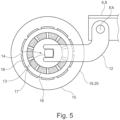
- at least one of the support rollers 20, 21 is electrically driven. Details of this drive, which for all embodiments according to Figures 1 to 4 suitable are in figure 5 illustrated.
- the axle end 13 and thus the entire axle of the support roller 20, 21 is firmly connected to a stator 16 of an electric motor.
- a stator 16 of an electric motor in the in figure 5 case outlined is an anti-twist device of the stator 16 given by a wrench size at the axle end 13 and the correspondingly contoured retaining slot 14.
- the rotor 19 is equipped with permanent magnets 18 in the exemplary embodiment.
- recognizable adjustment axis EA is only available as an option.
- a non-rotatable connection is established between the rotor 19 and the idler roller shell, designated 15, of the idler roller 20, so that the idler roller shell 15 is electrically driven directly, ie without a gear. Due to the design of the rotor 19 as an external rotor equipped with permanent magnets, no power supply to the rotor 19 is required.
- the idler roller shell 15 is mounted by means of bearings, not shown, in particular roller bearings. A separate storage of the rotor 19 is not available.
- the drive belt 31 can be guided in the form of a slight belt trough, which produces an enlarged contact surface with the conveyor belt 35, which is associated with the ability to transmit larger forces.
- the distance between the support rollers 20, 21 can be increased in order to provide an extended infeed and outfeed length and thus enable a low-stress deformation of the drive belt 31 and a large area of the conveyor belt 35 to nestle against the drive belt 31.
- a first way of tensioning the drive belt 31 is in figure 3 illustrated.
- a bracket 26 on the arm 12 which is designed as a sheet metal profile.
- a threaded rod 24 is fixed to the bracket 26 with the aid of adjusting nuts 25 .
- An annular receptacle 27, which is coupled to the hub 13, can be adjusted by the threaded rod 24, so that the distance between the adjustment axis EA and the support roller axis, which is designated by TA, can be varied.
- This provides a belt tensioning device, designated 36, with which the tension of the drive belt 31 can be varied.
- the distance between the axes EA, TA can be varied by a spring mechanism as an alternative or in support of a locking mechanism.
- a cable 28 serving to transmit energy and signals is routed centrally through the hub 13 and is connected to the in 3 not shown in detail direct drive motor of the support roller 20 connected.
- the electrical connection of the support rollers 20,21 can also be carried out with all other designs of the support roller frame 1.
- the distance between the two support roller axles TA cannot be adjusted. Instead, in this case there are tensioning rollers 32 with which the drive belt 31 can be tensioned.
- the tensioning rollers 32 are components of a roller tensioning device, designated 37 , which can be attributed to the belt tensioning device 36 .
- Locking contours 33 which in figure 4 are indicated and are also referred to as a hole pattern, allow the determination of the tension rollers 32 and are located in the embodiment 4 on side plates 34, which are firmly connected to the side parts 7, 8 of the pivoting frame 6.
- the adjustment range of the tensioning rollers 32 is limited in such a way that the drive belt 31 is guided in all settings at a sufficient distance over the base plate 2, ie the cross brace of the supporting roller frame 1.
- the tensioning rollers 32 have the effect of increasing the contact surfaces between the support rollers 20, 21 and the drive belt 31, this effect being all the greater the more the tensioning rollers 32 are raised and the drive belt 31 is thus tensioned.
- the idlers 32 is the angle of wrap between support roller 20, 21 and drive belt 31 more than 180 °.
- the drive belt 31 can not only be driven by the support rollers 20, 21, but can also be braked if necessary, for example for the purpose of an emergency stop of the conveyor belt 35.
- a braking torque can be generated by the electric direct drive 16, 19 and, on the other hand, a braking torque acting on the support roller 20, 21 can be generated by means of an optional mechanical brake (not shown).
Landscapes
- Engineering & Computer Science (AREA)
- Mechanical Engineering (AREA)
- Rollers For Roller Conveyors For Transfer (AREA)
- Structure Of Belt Conveyors (AREA)
Claims (9)
- Châssis de rouleaux de support d'un système de bande transporteuse, pourvu d'un cadre pivotant (6), sur lequel sont logés au moins deux rouleaux de support {20, 21), au moins l'un desdits deux rouleaux de support (20, 21) comportant un auto-entraînement électrique, les rouleaux de support (20, 21) logés sur le cadre pivotant (6) étant logés chacun sur des bras (12), lesquels sont articulés de manière pivotante sur des parties latérales (7, 8) du cadre pivotant (6), caractérisé en ce que l'auto-entraînement électrique est conçu sous la forme d'un entraînement (16, 19) sans réducteur, deux rouleaux de support (20, 21) logés sur le cadre pivotant (6), dont au moins l'un est directement entraîné électriquement étant directement enlacés par une courroie d'entraînement (31) dont la tension est variable au moyen d'un dispositif tendeur (36) de courroie, l'écart entre l'axe de rotation (TA) d'un rouleau de support (20, 21) étant réglable par l'axe de pivotement (EA) des bras (12) associés.
- Châssis de rouleaux de support d'un système de bande transporteuse, pourvu d'un cadre pivotant (6), sur lequel sont logés au moins deux rouleaux de support {20, 21), au moins l'un desdits deux rouleaux de support (20, 21) comportant un auto-entraînement électrique, caractérisé en ce que l'auto-entraînement électrique est conçu sous la forme d'un entraînement (16, 19) sans réducteur, deux rouleaux de support (20, 21) logés sur le cadre pivotant (6), dont au moins l'un est directement entraîné électriquement étant directement enlacés par une courroie d'entraînement (31) dont la tension est variable au moyen d'un dispositif tendeur (36) de courroie, qui comprend deux rouleaux tendeurs (32), placés à côté de l'axe de pivotement (SW) du cadre pivotant (6), en symétrie spéculaire par rapport à l'axe de pivotement (SW), dont le positionnement est respectivement variable.
- Châssis de rouleaux de support selon la revendication 1 ou 2, caractérisé en ce que l'entraînement (16, 19) sans réducteur est conçu sous la forme d'un moteur à induit extérieur pourvu d'un stator (16) interne et d'un rotor creux (19), relié de manière solidaire en rotation avec l'enveloppe du rouleau de support (20, 21) .
- Châssis de rouleaux de support selon la revendication 3, caractérisé en ce que l'entraînement (16, 19) sans réducteur est conçu sous la forme d'un moteur à entraînement direct excité par aimant permanent.
- Châssis de rouleaux de support selon l'une quelconque des revendications 1 à 4, caractérisé en ce que deux rouleaux de support (20, 21) logés sur le cadre pivotant (6) sont directement entraînés électriquement et électroniquement synchronisés.
- Châssis de rouleaux de support selon l'une quelconque des revendications 1 à 4, caractérisé en ce que seul l'un des rouleaux de support (20, 21) logés sur le cadre pivotant (6) est directement entraîné électriquement.
- Châssis de rouleaux de support selon la revendication 2, caractérisé en ce que le positionnement de chaque rouleau tendeur (32) est variable par un dispositif tendeur (37) de rouleau, notamment un dispositif tendeur automatique, le dispositif tendeur (37) de rouleau comprenant deux leviers tendeurs (33) articulés sur le cadre pivotant (6).
- Châssis de rouleaux de support selon l'une quelconque des revendications 1 à 7, caractérisé par deux rouleaux de support (22, 23) latéraux, non entraînés, flanquant le cadre pivotant (6), placés en inclinaison par rapport au cadre pivotant (6).
- Châssis de rouleaux de support selon l'une quelconque des revendications 1 à 8, caractérisé en ce qu'en relation par rapport à un cadre de pose (5) le logeant de manière basculable, le cadre pivotant (6) est réglable en hauteur, notamment réglable en hauteur automatiquement.
Applications Claiming Priority (2)
| Application Number | Priority Date | Filing Date | Title |
|---|---|---|---|
| DE102018107127.2A DE102018107127B4 (de) | 2018-03-26 | 2018-03-26 | Tragrollengestell mit Schwenkrahmen für eine Förderbandanlage |
| PCT/EP2019/055701 WO2019185322A1 (fr) | 2018-03-26 | 2019-03-07 | Châssis de rouleaux de support muni d'un cadre pivotant destiné à un système de bande transporteuse |
Publications (2)
| Publication Number | Publication Date |
|---|---|
| EP3774602A1 EP3774602A1 (fr) | 2021-02-17 |
| EP3774602B1 true EP3774602B1 (fr) | 2023-08-30 |
Family
ID=65724398
Family Applications (1)
| Application Number | Title | Priority Date | Filing Date |
|---|---|---|---|
| EP19709901.3A Active EP3774602B1 (fr) | 2018-03-26 | 2019-03-07 | Châssis de rouleaux de support muni d'un cadre pivotant destiné à un système de bande transporteuse |
Country Status (7)
| Country | Link |
|---|---|
| EP (1) | EP3774602B1 (fr) |
| CN (1) | CN111741912B (fr) |
| AU (1) | AU2019245717B2 (fr) |
| CL (1) | CL2020002072A1 (fr) |
| DE (1) | DE102018107127B4 (fr) |
| PE (1) | PE20210529A1 (fr) |
| WO (1) | WO2019185322A1 (fr) |
Family Cites Families (22)
| Publication number | Priority date | Publication date | Assignee | Title |
|---|---|---|---|---|
| DE1178359B (de) | 1962-08-02 | 1964-09-17 | Weserhuette Ag Eisenwerk | Zwischenantrieb mit endlosem Mitnahmeband fuer einen Langstreckenfoerderer |
| GB1088422A (en) | 1964-01-07 | 1967-10-25 | Solar Thomson Eng Co Ltd | Conveyor belt |
| US3407673A (en) * | 1966-05-19 | 1968-10-29 | Raymond J. Slezak | Belt tracking apparatus |
| DE2146218C3 (de) | 1971-09-16 | 1974-09-26 | Pohlig-Heckel-Bleichert Vereinigte Maschinenfabriken Ag, 5000 Koeln | Muldenforderbandanlage |
| US3880275A (en) * | 1973-04-20 | 1975-04-29 | Hans Fischer | Trough belt conveyor |
| DE2643559A1 (de) | 1976-09-28 | 1978-03-30 | Eickhoff Geb | Zwischenantrieb fuer endlose gurtfoerderbaender |
| GB2012700B (en) * | 1977-12-17 | 1982-05-12 | Ludwig Ing Buero Foerdertech | Belt conveyor |
| DE3724126C2 (de) | 1987-07-21 | 1995-04-13 | Telair Int Cargo Sys Gmbh | Antriebsrolleneinheit |
| DE3903971C1 (fr) * | 1989-02-10 | 1989-09-28 | Helmut Dipl.-Ing. 5162 Niederzier De Geppert | |
| DE20205428U1 (de) | 2002-04-09 | 2002-08-29 | HUPFER Metallwerke GmbH & Co., 48653 Coesfeld | Förderband für Großküchen |
| DE20305351U1 (de) | 2003-04-02 | 2003-06-18 | Maschinenfabrik Ernst Hese GmbH, 45881 Gelsenkirchen | Treibgurt-Traggurt-Antrieb |
| DE102006005158A1 (de) | 2006-02-04 | 2007-08-16 | Abb Patent Gmbh | Antriebstrommel eines Gurtbandförderers und Baukastensystem zur Bildung einer Antriebstrommel |
| US9359142B2 (en) * | 2012-03-20 | 2016-06-07 | P. Ellegaard A/S | Hygienic drum motor |
| KR101388036B1 (ko) * | 2013-01-31 | 2014-04-23 | 현대제철 주식회사 | 연원료 이송장치 |
| DE202013011823U1 (de) | 2013-08-02 | 2014-07-31 | Artur Küpper GmbH & Co. KG | Tragrollengirlandensystem |
| DE102014107591A1 (de) | 2014-05-28 | 2015-12-03 | Artur Küpper GmbH & Co. KG | Förderbandanlage mit dezentralem Förderbandantrieb und Verfahren zum Betrieb der Förderbandanlage |
| DE202015101778U1 (de) | 2014-08-21 | 2015-04-23 | Jiangxi Gongbu Machinery Co., Ltd. | Außenläufermotor |
| DE102014216733B4 (de) | 2014-08-22 | 2018-10-11 | Takraf Gmbh | Tragrollenantrieb für eine Bandförderanlage |
| EP3034437B1 (fr) | 2014-12-15 | 2018-10-31 | MTA Systems GmbH | Unité d'entraînement pour un rouleau de transport |
| DE102015115831A1 (de) | 2015-09-18 | 2017-03-23 | Artur Küpper GmbH & Co. KG | Tragrolle für eine Förderanlage |
| WO2017068055A1 (fr) | 2015-10-20 | 2017-04-27 | Artur Küpper GmbH & Co. KG | Châssis de rouleaux de support muni d'un cadre pivotant et de fentes de guidage et de retenue horizontales |
| WO2017123534A1 (fr) * | 2016-01-11 | 2017-07-20 | Therm-L-Tech Systems, LLC | Système intégré de moteur à entraînement direct |
-
2018
- 2018-03-26 DE DE102018107127.2A patent/DE102018107127B4/de active Active
-
2019
- 2019-03-07 PE PE2020001204A patent/PE20210529A1/es unknown
- 2019-03-07 WO PCT/EP2019/055701 patent/WO2019185322A1/fr not_active Ceased
- 2019-03-07 CN CN201980014230.4A patent/CN111741912B/zh active Active
- 2019-03-07 EP EP19709901.3A patent/EP3774602B1/fr active Active
- 2019-03-07 AU AU2019245717A patent/AU2019245717B2/en active Active
-
2020
- 2020-08-10 CL CL2020002072A patent/CL2020002072A1/es unknown
Also Published As
| Publication number | Publication date |
|---|---|
| AU2019245717B2 (en) | 2021-10-28 |
| CL2020002072A1 (es) | 2020-12-11 |
| AU2019245717A1 (en) | 2020-10-08 |
| BR112020016428A2 (pt) | 2020-12-15 |
| CN111741912A (zh) | 2020-10-02 |
| PE20210529A1 (es) | 2021-03-17 |
| EP3774602A1 (fr) | 2021-02-17 |
| CN111741912B (zh) | 2022-03-29 |
| DE102018107127B4 (de) | 2024-03-07 |
| DE102018107127A1 (de) | 2019-09-26 |
| WO2019185322A1 (fr) | 2019-10-03 |
Similar Documents
| Publication | Publication Date | Title |
|---|---|---|
| DE69522244T2 (de) | Gleichgewichtshebezeug und materialtransportsystem | |
| EP2250108B1 (fr) | Dispositif et procédé de transport de produits un à un à l'aide d'un dispositif d'entraînement à embrayage | |
| EP2222981A1 (fr) | Moyen d'entraînement et entraînement par chaîne | |
| DE19510649C2 (de) | Transportvorrichtung | |
| EP1700811A1 (fr) | Ascenseur | |
| EP2616370A1 (fr) | Courbe de transporteur à rouleaux pourvue d'une courroie d'entraînement ronde | |
| DE4428262C1 (de) | Motorisch angetriebener Fensterheber | |
| EP0534959A1 (fr) | Dispositif de bobinage pour machines a decouper a roulettes du type a cylindre d'appui ou similaire. | |
| EP0960842A1 (fr) | Convoyeur à rouleaux avec des rouleaux de support entrainés | |
| EP3774602B1 (fr) | Châssis de rouleaux de support muni d'un cadre pivotant destiné à un système de bande transporteuse | |
| EP3546399B1 (fr) | Dispositif de levage et de transport et transporteur à vis doté du dispositif de levage et de transport | |
| EP0636559B1 (fr) | Transporteur à bande courbe | |
| DE2843244A1 (de) | Walzenstrasse mit zwei walzgeruestgruppen in blockform-anordnung | |
| DE10117849C2 (de) | Spiralfördersystem | |
| DE102015013618A1 (de) | Spinn- oder Zwirnmaschine mit hubbewegbarer Spindelbank | |
| DE3905345A1 (de) | Vorrichtung zum reibschluessigen antrieb eines gegenstands, insbesondere einer trommel | |
| EP2437992B1 (fr) | Dispositif de transport destiné à transporter des marchandises | |
| EP2089305B1 (fr) | Mécanisme d'entraînement pour ascenseur | |
| EP2785540B1 (fr) | Dispositif d'accouplement | |
| DE102009027299A1 (de) | Antriebsvorrichtung | |
| EP4296412B1 (fr) | Dispositif de fabrication d'un rouleau de ouate | |
| EP0560102B1 (fr) | Dispositif pour l'entraînement à sa périphérie d'un rouleau de matériau en bande | |
| DE4327860C1 (de) | Vorrichtung zur drehenden Lagerung einer Kabeltrommel | |
| DE19715058A1 (de) | Antriebseinrichtung eines Gurtförderers | |
| DE10348737A1 (de) | Elektrohängebahn |
Legal Events
| Date | Code | Title | Description |
|---|---|---|---|
| STAA | Information on the status of an ep patent application or granted ep patent |
Free format text: STATUS: UNKNOWN |
|
| STAA | Information on the status of an ep patent application or granted ep patent |
Free format text: STATUS: THE INTERNATIONAL PUBLICATION HAS BEEN MADE |
|
| PUAI | Public reference made under article 153(3) epc to a published international application that has entered the european phase |
Free format text: ORIGINAL CODE: 0009012 |
|
| STAA | Information on the status of an ep patent application or granted ep patent |
Free format text: STATUS: REQUEST FOR EXAMINATION WAS MADE |
|
| 17P | Request for examination filed |
Effective date: 20200914 |
|
| AK | Designated contracting states |
Kind code of ref document: A1 Designated state(s): AL AT BE BG CH CY CZ DE DK EE ES FI FR GB GR HR HU IE IS IT LI LT LU LV MC MK MT NL NO PL PT RO RS SE SI SK SM TR |
|
| AX | Request for extension of the european patent |
Extension state: BA ME |
|
| DAV | Request for validation of the european patent (deleted) | ||
| DAX | Request for extension of the european patent (deleted) | ||
| GRAP | Despatch of communication of intention to grant a patent |
Free format text: ORIGINAL CODE: EPIDOSNIGR1 |
|
| STAA | Information on the status of an ep patent application or granted ep patent |
Free format text: STATUS: GRANT OF PATENT IS INTENDED |
|
| INTG | Intention to grant announced |
Effective date: 20230601 |
|
| GRAS | Grant fee paid |
Free format text: ORIGINAL CODE: EPIDOSNIGR3 |
|
| GRAA | (expected) grant |
Free format text: ORIGINAL CODE: 0009210 |
|
| STAA | Information on the status of an ep patent application or granted ep patent |
Free format text: STATUS: THE PATENT HAS BEEN GRANTED |
|
| AK | Designated contracting states |
Kind code of ref document: B1 Designated state(s): AL AT BE BG CH CY CZ DE DK EE ES FI FR GB GR HR HU IE IS IT LI LT LU LV MC MK MT NL NO PL PT RO RS SE SI SK SM TR |
|
| REG | Reference to a national code |
Ref country code: GB Ref legal event code: FG4D Free format text: NOT ENGLISH |
|
| REG | Reference to a national code |
Ref country code: CH Ref legal event code: EP |
|
| REG | Reference to a national code |
Ref country code: DE Ref legal event code: R096 Ref document number: 502019009139 Country of ref document: DE |
|
| REG | Reference to a national code |
Ref country code: IE Ref legal event code: FG4D Free format text: LANGUAGE OF EP DOCUMENT: GERMAN |
|
| REG | Reference to a national code |
Ref country code: LT Ref legal event code: MG9D |
|
| REG | Reference to a national code |
Ref country code: NL Ref legal event code: MP Effective date: 20230830 |
|
| PG25 | Lapsed in a contracting state [announced via postgrant information from national office to epo] |
Ref country code: GR Free format text: LAPSE BECAUSE OF FAILURE TO SUBMIT A TRANSLATION OF THE DESCRIPTION OR TO PAY THE FEE WITHIN THE PRESCRIBED TIME-LIMIT Effective date: 20231201 |
|
| PG25 | Lapsed in a contracting state [announced via postgrant information from national office to epo] |
Ref country code: IS Free format text: LAPSE BECAUSE OF FAILURE TO SUBMIT A TRANSLATION OF THE DESCRIPTION OR TO PAY THE FEE WITHIN THE PRESCRIBED TIME-LIMIT Effective date: 20231230 |
|
| PG25 | Lapsed in a contracting state [announced via postgrant information from national office to epo] |
Ref country code: SE Free format text: LAPSE BECAUSE OF FAILURE TO SUBMIT A TRANSLATION OF THE DESCRIPTION OR TO PAY THE FEE WITHIN THE PRESCRIBED TIME-LIMIT Effective date: 20230830 Ref country code: RS Free format text: LAPSE BECAUSE OF FAILURE TO SUBMIT A TRANSLATION OF THE DESCRIPTION OR TO PAY THE FEE WITHIN THE PRESCRIBED TIME-LIMIT Effective date: 20230830 Ref country code: NO Free format text: LAPSE BECAUSE OF FAILURE TO SUBMIT A TRANSLATION OF THE DESCRIPTION OR TO PAY THE FEE WITHIN THE PRESCRIBED TIME-LIMIT Effective date: 20231130 Ref country code: LV Free format text: LAPSE BECAUSE OF FAILURE TO SUBMIT A TRANSLATION OF THE DESCRIPTION OR TO PAY THE FEE WITHIN THE PRESCRIBED TIME-LIMIT Effective date: 20230830 Ref country code: LT Free format text: LAPSE BECAUSE OF FAILURE TO SUBMIT A TRANSLATION OF THE DESCRIPTION OR TO PAY THE FEE WITHIN THE PRESCRIBED TIME-LIMIT Effective date: 20230830 Ref country code: IS Free format text: LAPSE BECAUSE OF FAILURE TO SUBMIT A TRANSLATION OF THE DESCRIPTION OR TO PAY THE FEE WITHIN THE PRESCRIBED TIME-LIMIT Effective date: 20231230 Ref country code: HR Free format text: LAPSE BECAUSE OF FAILURE TO SUBMIT A TRANSLATION OF THE DESCRIPTION OR TO PAY THE FEE WITHIN THE PRESCRIBED TIME-LIMIT Effective date: 20230830 Ref country code: GR Free format text: LAPSE BECAUSE OF FAILURE TO SUBMIT A TRANSLATION OF THE DESCRIPTION OR TO PAY THE FEE WITHIN THE PRESCRIBED TIME-LIMIT Effective date: 20231201 Ref country code: FI Free format text: LAPSE BECAUSE OF FAILURE TO SUBMIT A TRANSLATION OF THE DESCRIPTION OR TO PAY THE FEE WITHIN THE PRESCRIBED TIME-LIMIT Effective date: 20230830 |
|
| PG25 | Lapsed in a contracting state [announced via postgrant information from national office to epo] |
Ref country code: PL Free format text: LAPSE BECAUSE OF FAILURE TO SUBMIT A TRANSLATION OF THE DESCRIPTION OR TO PAY THE FEE WITHIN THE PRESCRIBED TIME-LIMIT Effective date: 20230830 Ref country code: NL Free format text: LAPSE BECAUSE OF FAILURE TO SUBMIT A TRANSLATION OF THE DESCRIPTION OR TO PAY THE FEE WITHIN THE PRESCRIBED TIME-LIMIT Effective date: 20230830 |
|
| PG25 | Lapsed in a contracting state [announced via postgrant information from national office to epo] |
Ref country code: ES Free format text: LAPSE BECAUSE OF FAILURE TO SUBMIT A TRANSLATION OF THE DESCRIPTION OR TO PAY THE FEE WITHIN THE PRESCRIBED TIME-LIMIT Effective date: 20230830 |
|
| PG25 | Lapsed in a contracting state [announced via postgrant information from national office to epo] |
Ref country code: SM Free format text: LAPSE BECAUSE OF FAILURE TO SUBMIT A TRANSLATION OF THE DESCRIPTION OR TO PAY THE FEE WITHIN THE PRESCRIBED TIME-LIMIT Effective date: 20230830 Ref country code: RO Free format text: LAPSE BECAUSE OF FAILURE TO SUBMIT A TRANSLATION OF THE DESCRIPTION OR TO PAY THE FEE WITHIN THE PRESCRIBED TIME-LIMIT Effective date: 20230830 Ref country code: ES Free format text: LAPSE BECAUSE OF FAILURE TO SUBMIT A TRANSLATION OF THE DESCRIPTION OR TO PAY THE FEE WITHIN THE PRESCRIBED TIME-LIMIT Effective date: 20230830 Ref country code: EE Free format text: LAPSE BECAUSE OF FAILURE TO SUBMIT A TRANSLATION OF THE DESCRIPTION OR TO PAY THE FEE WITHIN THE PRESCRIBED TIME-LIMIT Effective date: 20230830 Ref country code: DK Free format text: LAPSE BECAUSE OF FAILURE TO SUBMIT A TRANSLATION OF THE DESCRIPTION OR TO PAY THE FEE WITHIN THE PRESCRIBED TIME-LIMIT Effective date: 20230830 Ref country code: CZ Free format text: LAPSE BECAUSE OF FAILURE TO SUBMIT A TRANSLATION OF THE DESCRIPTION OR TO PAY THE FEE WITHIN THE PRESCRIBED TIME-LIMIT Effective date: 20230830 Ref country code: SK Free format text: LAPSE BECAUSE OF FAILURE TO SUBMIT A TRANSLATION OF THE DESCRIPTION OR TO PAY THE FEE WITHIN THE PRESCRIBED TIME-LIMIT Effective date: 20230830 Ref country code: PT Free format text: LAPSE BECAUSE OF FAILURE TO SUBMIT A TRANSLATION OF THE DESCRIPTION OR TO PAY THE FEE WITHIN THE PRESCRIBED TIME-LIMIT Effective date: 20240102 |
|
| REG | Reference to a national code |
Ref country code: DE Ref legal event code: R097 Ref document number: 502019009139 Country of ref document: DE |
|
| PLBE | No opposition filed within time limit |
Free format text: ORIGINAL CODE: 0009261 |
|
| STAA | Information on the status of an ep patent application or granted ep patent |
Free format text: STATUS: NO OPPOSITION FILED WITHIN TIME LIMIT |
|
| PG25 | Lapsed in a contracting state [announced via postgrant information from national office to epo] |
Ref country code: SI Free format text: LAPSE BECAUSE OF FAILURE TO SUBMIT A TRANSLATION OF THE DESCRIPTION OR TO PAY THE FEE WITHIN THE PRESCRIBED TIME-LIMIT Effective date: 20230830 |
|
| 26N | No opposition filed |
Effective date: 20240603 |
|
| REG | Reference to a national code |
Ref country code: CH Ref legal event code: PL |
|
| PG25 | Lapsed in a contracting state [announced via postgrant information from national office to epo] |
Ref country code: BG Free format text: LAPSE BECAUSE OF FAILURE TO SUBMIT A TRANSLATION OF THE DESCRIPTION OR TO PAY THE FEE WITHIN THE PRESCRIBED TIME-LIMIT Effective date: 20230830 |
|
| PG25 | Lapsed in a contracting state [announced via postgrant information from national office to epo] |
Ref country code: LU Free format text: LAPSE BECAUSE OF NON-PAYMENT OF DUE FEES Effective date: 20240307 |
|
| PG25 | Lapsed in a contracting state [announced via postgrant information from national office to epo] |
Ref country code: MC Free format text: LAPSE BECAUSE OF FAILURE TO SUBMIT A TRANSLATION OF THE DESCRIPTION OR TO PAY THE FEE WITHIN THE PRESCRIBED TIME-LIMIT Effective date: 20230830 |
|
| GBPC | Gb: european patent ceased through non-payment of renewal fee |
Effective date: 20240307 |
|
| PG25 | Lapsed in a contracting state [announced via postgrant information from national office to epo] |
Ref country code: MC Free format text: LAPSE BECAUSE OF FAILURE TO SUBMIT A TRANSLATION OF THE DESCRIPTION OR TO PAY THE FEE WITHIN THE PRESCRIBED TIME-LIMIT Effective date: 20230830 Ref country code: LU Free format text: LAPSE BECAUSE OF NON-PAYMENT OF DUE FEES Effective date: 20240307 Ref country code: BG Free format text: LAPSE BECAUSE OF FAILURE TO SUBMIT A TRANSLATION OF THE DESCRIPTION OR TO PAY THE FEE WITHIN THE PRESCRIBED TIME-LIMIT Effective date: 20230830 |
|
| REG | Reference to a national code |
Ref country code: BE Ref legal event code: MM Effective date: 20240331 |
|
| PG25 | Lapsed in a contracting state [announced via postgrant information from national office to epo] |
Ref country code: BE Free format text: LAPSE BECAUSE OF NON-PAYMENT OF DUE FEES Effective date: 20240331 |
|
| PG25 | Lapsed in a contracting state [announced via postgrant information from national office to epo] |
Ref country code: GB Free format text: LAPSE BECAUSE OF NON-PAYMENT OF DUE FEES Effective date: 20240307 |
|
| PG25 | Lapsed in a contracting state [announced via postgrant information from national office to epo] |
Ref country code: FR Free format text: LAPSE BECAUSE OF NON-PAYMENT OF DUE FEES Effective date: 20240331 |
|
| PG25 | Lapsed in a contracting state [announced via postgrant information from national office to epo] |
Ref country code: IE Free format text: LAPSE BECAUSE OF NON-PAYMENT OF DUE FEES Effective date: 20240307 |
|
| PG25 | Lapsed in a contracting state [announced via postgrant information from national office to epo] |
Ref country code: IE Free format text: LAPSE BECAUSE OF NON-PAYMENT OF DUE FEES Effective date: 20240307 Ref country code: GB Free format text: LAPSE BECAUSE OF NON-PAYMENT OF DUE FEES Effective date: 20240307 Ref country code: FR Free format text: LAPSE BECAUSE OF NON-PAYMENT OF DUE FEES Effective date: 20240331 Ref country code: BE Free format text: LAPSE BECAUSE OF NON-PAYMENT OF DUE FEES Effective date: 20240331 Ref country code: CH Free format text: LAPSE BECAUSE OF NON-PAYMENT OF DUE FEES Effective date: 20240331 |
|
| PGFP | Annual fee paid to national office [announced via postgrant information from national office to epo] |
Ref country code: DE Payment date: 20250319 Year of fee payment: 7 |
|
| REG | Reference to a national code |
Ref country code: AT Ref legal event code: MM01 Ref document number: 1605207 Country of ref document: AT Kind code of ref document: T Effective date: 20240307 |
|
| PGFP | Annual fee paid to national office [announced via postgrant information from national office to epo] |
Ref country code: IT Payment date: 20250331 Year of fee payment: 7 |
|
| PG25 | Lapsed in a contracting state [announced via postgrant information from national office to epo] |
Ref country code: AT Free format text: LAPSE BECAUSE OF NON-PAYMENT OF DUE FEES Effective date: 20240307 |
|
| PG25 | Lapsed in a contracting state [announced via postgrant information from national office to epo] |
Ref country code: CY Free format text: LAPSE BECAUSE OF FAILURE TO SUBMIT A TRANSLATION OF THE DESCRIPTION OR TO PAY THE FEE WITHIN THE PRESCRIBED TIME-LIMIT; INVALID AB INITIO Effective date: 20190307 |
|
| PG25 | Lapsed in a contracting state [announced via postgrant information from national office to epo] |
Ref country code: HU Free format text: LAPSE BECAUSE OF FAILURE TO SUBMIT A TRANSLATION OF THE DESCRIPTION OR TO PAY THE FEE WITHIN THE PRESCRIBED TIME-LIMIT; INVALID AB INITIO Effective date: 20190307 |
|
| PG25 | Lapsed in a contracting state [announced via postgrant information from national office to epo] |
Ref country code: TR Free format text: LAPSE BECAUSE OF FAILURE TO SUBMIT A TRANSLATION OF THE DESCRIPTION OR TO PAY THE FEE WITHIN THE PRESCRIBED TIME-LIMIT Effective date: 20230830 |