EP3774603B1 - Transporteur à vibrations - Google Patents
Transporteur à vibrations Download PDFInfo
- Publication number
- EP3774603B1 EP3774603B1 EP19732114.4A EP19732114A EP3774603B1 EP 3774603 B1 EP3774603 B1 EP 3774603B1 EP 19732114 A EP19732114 A EP 19732114A EP 3774603 B1 EP3774603 B1 EP 3774603B1
- Authority
- EP
- European Patent Office
- Prior art keywords
- arrangement
- vibration
- conveying element
- conveyor
- vibratory conveyor
- Prior art date
- Legal status (The legal status is an assumption and is not a legal conclusion. Google has not performed a legal analysis and makes no representation as to the accuracy of the status listed.)
- Active
Links
Images


Classifications
-
- B—PERFORMING OPERATIONS; TRANSPORTING
- B65—CONVEYING; PACKING; STORING; HANDLING THIN OR FILAMENTARY MATERIAL
- B65G—TRANSPORT OR STORAGE DEVICES, e.g. CONVEYORS FOR LOADING OR TIPPING, SHOP CONVEYOR SYSTEMS OR PNEUMATIC TUBE CONVEYORS
- B65G27/00—Jigging conveyors
- B65G27/08—Supports or mountings for load-carriers, e.g. framework, bases, spring arrangements
-
- B—PERFORMING OPERATIONS; TRANSPORTING
- B65—CONVEYING; PACKING; STORING; HANDLING THIN OR FILAMENTARY MATERIAL
- B65G—TRANSPORT OR STORAGE DEVICES, e.g. CONVEYORS FOR LOADING OR TIPPING, SHOP CONVEYOR SYSTEMS OR PNEUMATIC TUBE CONVEYORS
- B65G27/00—Jigging conveyors
- B65G27/10—Applications of devices for generating or transmitting jigging movements
- B65G27/28—Applications of devices for generating or transmitting jigging movements with provision for dynamic balancing
- B65G27/30—Applications of devices for generating or transmitting jigging movements with provision for dynamic balancing by means of an oppositely-moving mass, e.g. a second conveyor
-
- B—PERFORMING OPERATIONS; TRANSPORTING
- B65—CONVEYING; PACKING; STORING; HANDLING THIN OR FILAMENTARY MATERIAL
- B65G—TRANSPORT OR STORAGE DEVICES, e.g. CONVEYORS FOR LOADING OR TIPPING, SHOP CONVEYOR SYSTEMS OR PNEUMATIC TUBE CONVEYORS
- B65G27/00—Jigging conveyors
- B65G27/10—Applications of devices for generating or transmitting jigging movements
- B65G27/32—Applications of devices for generating or transmitting jigging movements with means for controlling direction, frequency or amplitude of vibration or shaking movement
-
- B—PERFORMING OPERATIONS; TRANSPORTING
- B65—CONVEYING; PACKING; STORING; HANDLING THIN OR FILAMENTARY MATERIAL
- B65G—TRANSPORT OR STORAGE DEVICES, e.g. CONVEYORS FOR LOADING OR TIPPING, SHOP CONVEYOR SYSTEMS OR PNEUMATIC TUBE CONVEYORS
- B65G43/00—Control devices, e.g. for safety, warning or fault-correcting
-
- B—PERFORMING OPERATIONS; TRANSPORTING
- B65—CONVEYING; PACKING; STORING; HANDLING THIN OR FILAMENTARY MATERIAL
- B65G—TRANSPORT OR STORAGE DEVICES, e.g. CONVEYORS FOR LOADING OR TIPPING, SHOP CONVEYOR SYSTEMS OR PNEUMATIC TUBE CONVEYORS
- B65G2203/00—Indexing code relating to control or detection of the articles or the load carriers during conveying
- B65G2203/04—Detection means
- B65G2203/042—Sensors
Definitions
- the present invention relates to a vibratory feeder according to the preamble of claim 1.
- Such vibrating conveyors are used in many branches of industry, for all sorts of materials, as long as they can be conveyed at all by a vibrating conveyor.
- the loose materials are discharged onto a conveying element, usually a conveying chute, which then performs a cyclical forward/upward movement with a corresponding reverse movement - the vibration - whereby the individual particles of the material are thrown forward and at the same time slightly upwards at a throwing angle.
- the conveying element performs the reverse movement before the particles rest on it again, so that the particles can be conveyed one step further with the next forward/upward movement. With small deflections, it can also be conveyed forwards due to differences in friction during forward and reverse movement.
- EP1460006A1 discloses a vibratory feeder according to the preamble of claim 1.
- Vibration conveyors correspondingly have a vibrating carrier arrangement for the exchangeable conveying element resting on it, designed for example depending on the material or other criteria, with the carrier arrangement being set into the desired vibration by a drive arrangement.
- Vibration conveyors especially those with a conveyor trough, are difficult to design, are largely manufactured according to empirical findings and are compared in experiments with the material to be conveyed in terms of frequency and throw angle. Some concepts work as desired, others show a poor level of funding, without the reasons for this being transparent in the specific case.
- a disadvantage of the known vibratory conveyors relates to the time-delayed controllability of the mass flow output at the end of the conveyor element or the conveyor chute, which more or less constantly drifts somewhat without regulation, whether this is because of the irregular filling of the conveyor element or because of other influences, which is particularly the case with gravimetric dosing (when a vibratory feeder is placed on a scale) is problematic, but also creates problems with volumetric dosing.
- FIG 1a shows schematically and by way of example a vibration conveyor 1 according to the prior art, which is mounted on the base 2 via a bearing arrangement, here elastic feet or supports 3a, 3b.
- a drive unit 4 for a carrier arrangement 5 can be seen, on which in turn a conveying element designed here as a conveying channel 6 is arranged, which is filled with bulk material 9 (e.g. grain, pharmaceutical products, plastic granules and powders of all kinds or metallic materials of all kinds, etc.) is loaded.
- the vibratory movement of the carrier arrangement 5 also vibrates the conveying chute 6 so that the bulk material 9 ′ is discharged from the vibrating conveyor 1 at the end of the front section 8b of the conveying chute 6 .
- the drive unit 4 has a vibration drive 10, which in the embodiment shown is designed as an AC-carrying coil that forms a periodic magnetic field during operation and thus acts on a magnet 11, which in turn is arranged on the carrier arrangement 5 and moves it.
- the leaf springs 12a and 12b form drive levers for the carrier assembly 5, are slightly inclined with regard to the throwing angle and are set in the vibrating movement indicated by the double arrows 13a, b by the vibration drive 10, so that the carrier assembly 5, due to its cyclic parallel displacement relative to a
- the base plate 14 of the drive unit 4 executes a vibratory oscillation, which generates the mass flow m of the material to be conveyed or bulk material 9 in the conveying direction x in accordance with the throwing angle given by the direction of the double arrows 13a,b, see the coordinate system 15, whose x-axis is in the conveying direction and whose y-axis points vertically upwards.
- the direction of throw thus has a component forwards, in the x-direction, and upward
- the drive unit 4 has an operating frequency in the case of a drive unit according to figure 1 (ie with leaf springs) preferably, but not necessarily, corresponds to the resonant frequency of the drive unit 4, so that the leaf springs 12a, 12b oscillate at their resonant frequency, which is present according to the design of the drive unit 4.
- the drive unit can also have a mechanical drive so that there is no resonant frequency—it is then operated at an operating frequency.
- the result is a vibrating conveyor with a drive unit 4 that generates a vibration movement during operation, and a conveying element arranged on the drive unit, with the drive unit 4 having a carrier arrangement for the conveying element, which a portion (8a) is mounted on the carrier assembly 5 and has a freely extending portion 8b.
- Figure 1b shows two diagrams 20 and 25 for the flow of the bulk material in the conveyor chute 6 of the conventional vibratory conveyor 1 ( figure 1 ) according to a simulation by the applicant of the behavior of such a vibratory conveyor as a whole, with the flow of bulk material 9' at the front end of section 8b ( figure 1 ) of the conveyor trough 6 is shown.
- the diagrams of figure 2 the conditions with an increase in the delivery rate with an increase in the mass flow from approx. 0.012 kg/s to 0.031 kg/s.
- curve 21 shows the speed v x in the conveying direction x ( figure 1 ) of the bulk material 9' (as mentioned above at the front end 8b of the conveyor chute 9, see figure 1 ) over time in seconds (s).
- the vibratory conveyor is operated with a lower flow rate.
- the conveying rate is increased by increasing the amplitude of the vibration movement, with the bulk material speed v x (direction parallel to the conveyor chute 6) increasing practically without delay from the previous (section 22) to the new, stable speed in time section 24, See the jump point in time segment 23, in which the change in speed v x to the new value takes place.
- Diagram 25 shows the mass flow m in kg/s in conveying direction x (coordinate system 15, s. figure 1 ) of bulk material 9' at the front end 8b of the conveying trough 6.
- the mass flow is practically constant.
- the mass flow increases only slowly and only gradually stabilizes, with the result that the time segment 27 in which the change in the mass flow takes place lasts approximately 3.5 s.
- the time segment 28 the mass flow is stable at the new value.
- a hesitantly changing mass flow means poor controllability, at least with regard to time.
- the behavior of the mass flow over the length of the conveying chute 9 is the reason for the poor controllability of a vibrating conveyor according to FIG Figure 1a .
- the vibration conveyor 1 tilts about its necessarily elastic supports due to the vibration movement 3a and 3b, which means that the conveyor trough does not only have a translatory vibration movement in the direction of arrows 13a and 13b ( figure 1 ) executes, but also a rotation corresponding to the tilting movement, indicated by the double arrow 17.
- This rotation in turn has the result that the angle of throw changes over the length of the conveyor chute, because the conveyor chute 6 does not always remain horizontally aligned as a result of the rotation, but also at an angle due to the rotation.
- the freely extending portion 8b tends to oscillate in the plane of the Figure 1a , so that the front end of the section 8b moves up and down relative to the carrier arrangement 5, see the double arrow 16 in Figure 1a : the front end of the freely extending section 8b swings up and down in the y direction in relation to the carrier arrangement 5 and the rear section 8a mounted on it, the conveying chute 6 periodically bends upwards and downwards.
- this bending vibration is not only a consequence of the rotation (double arrow 17), but can also occur in a stably mounted rotary conveyor.
- the type of vibration depends on the design of the conveyor trough itself and on the material conveyed in it.
- the effect of the vertically oscillating conveyor chute 6 has effects comparable to the case of the rotation of the conveyor chute: due to the deflection of the conveyor chute, the angle of throw is not constant over its length, local accumulations of material form, which in turn result in poor controllability of the mass flow.
- vibrations can be weak and therefore of little relevance or strong and therefore highly relevant.
- the for the tilting or rotation of the vibration conveyor due to the elastic mounting 3a, 3b ( Figure 1a ) created diagrams according to the Figure 1b are therefore also meaningful and can be transferred to the case when there is no tilting of a vibratory conveyor, but its conveyor element itself starts to oscillate due to its specific design, which leads to a deformation with a changed throw angle.
- a disadvantage of such a vibration conveyor is that the controllability of the mass flow is improved, but remains unexpectedly difficult.
- the corresponding design of the carrier arrangement with adjustable pivot points still leads to a deflection of the conveyor chute, since the tumbling movement results in the rear section 8a being placed at an angle, while the front section 8b transitions into a horizontal alignment or should go over, which then oscillates depending on the amplitude of the vibrational movement with different deflection.
- the angle of throw is therefore not constant over the length and changes depending on the flow rate, which in turn leads to local accumulations of material, which can change with the changed flow rate depending on the operating state and negatively affect controllability.
- a correct setting in the specific case of a vibration conveyor running in a line is complex and difficult, for example because all operating states and possible conveyor chutes have to be anticipated and provided for in the mechanical adjustment of the pivot points.
- FIG 2 shows a view of an embodiment of a vibration conveyor 30 according to the invention, the basic structure of which is that of Figure 1a corresponds, wherein the conveying element designed as a conveying channel 31 has a vibrating arrangement 32 on its freely extending section 8b.
- this has a mass 33 which is designed as a spring-elastic tongue 34 spring arrangement with a fastening arrangement 35 is movably fixed to the conveying chute 6 and forms a resilient pendulum.
- section 8b of the conveyor trough 31 moves accordingly during operation of the vibratory conveyor 30, causing the mass 33 to oscillate relative to the conveyor trough 6 and relative to the drive arrangement 4, as shown by the double arrow 36 device, but with correct tuning such that the front section 8b only performs the translational movement according to the arrow 13c, i.e. a bending of the conveying chute 31 in the direction of the double arrow 16 ( Figure 1a ) essentially or completely omitted. A change in the angle of throw over the length of the conveyor chute 31 is thus reduced or prevented.
- the conveying chute 31, the vibration arrangement 32 and the drive arrangement 4 each have a resonant frequency (in the case of the drive arrangement 4 possibly an operating frequency), which are all different from one another. It is often the case that the resonant frequency of the conveyor chute 31, which is to be made stiff, is higher than that of the drive arrangement, which is in the range of 60 Hz in many prior-art vibratory conveyors. Then, according to the invention, the vibration arrangement 32 is to be designed in such a way that its resonant frequency is lower than the resonant or operating frequency of the drive arrangement 4.
- figure 3 shows the behavior of the conveying element 6 and the vibration arrangement 32 using the diagrams 40, 41 known per se for the forced, harmonic vibration of spring-mass systems.
- the conveying element represents such a spring-mass system, as does the vibration arrangement 32.
- the carrier arrangement 5 ( figure 2 ) oscillates during operation at its operating frequency, ie at this frequency, its front section 8b in relation to the rear section 8a and the pendulum mass 33 in relation to the front section 8b. It follows that all components oscillate at the same frequency, and one component excites the next to oscillate, ie the rear section 8a the front section 8b and this then the pendulum mass 33.
- the exciting oscillation ⁇ therefore always corresponds to the operating oscillation of the carrier arrangement 5, while the resonant frequency ⁇ 0 of the conveying element or the vibration arrangement 32 is different from this according to the invention.
- the phase between the driving force between the magnet 11 and the coil of the driving assembly 10 and the carrier assembly 5 is -90°, the force is 90° or ⁇ /2 leading in the case of resonance.
- the pendulum mass 33 oscillates almost or in opposition to the front end of the conveyor chute 6, with the result that it introduces a transverse force and a bending moment into the conveyor chute via the spring-elastic tongue 34, which is opposite to its current deflection, so that this deflection with a suitable tuning of the vibration arrangement 33 and the conveying element 6 is reduced or disappears.
- a spring-elastic vibration arrangement is provided, which is arranged and designed in such a way that it oscillates with respect to the vibration of the drive arrangement with the phase shift opposite to the phase shift of the conveying element.
- this phase shift is 180 ° or close to 180 ° , but is so large that the controllability of the vibration conveyor according to the invention is improved compared to an embodiment without a vibration arrangement.
- the conveyor element has a lower resonant frequency than the frequency of the carrier arrangement 6, the operating ranges 42, 45 in diagram 40 are reversed. However, the conveyor element and vibration arrangement still vibrate in push-pull mode, so that the deflection of the conveyor element is reduced or disappears.
- the natural frequencies of the conveying element 6 and the vibration arrangement 32 are different from the operating frequency of the carrier arrangement 4 and compared to this one of the natural frequencies is higher and the other is lower.
- the natural frequency of the conveying element is preferably higher than that of the vibrating arrangement 32.
- a conveying element in particular if it is designed as a conveying trough, can only open Because of its channel-shaped cross-section, it can generally be made comparatively stiff with respect to the vertical direction y, which leads to a comparatively high resonant frequency.
- a resonant frequency below the operating frequency can be present.
- conveying channels or conveying elements with a greater length can be considered than was previously the case from the aspect of regulating the conveying quantity.
- the vibration arrangement 32 preferably has a pendulum mass 33 and a resilient vibration arrangement 34, via which it is fixed to the conveying element 6.
- the spring-elastic vibration arrangement is further preferably designed as a leaf spring or rod-shaped spring 34 which is arranged parallel to the conveying direction of the conveying element.
- the vibration behavior of the conveying element is complex, also because the vibrational oscillation occurs in two directions (x and y, see Fig. Figure 1a ) he follows. Since the conveying chute 6 is stiff in the x direction, there is hardly any vibration component in the x direction of the front end of the free section 8b, but essentially only vibration in the vertical, ie in the y direction, ie the bending vibration mentioned above. For the pendulum mass 32 this still means that it moves on an elliptical path and the movements in the x direction can have an influence.
- a first standardized adjustment of the conveying element and vibration arrangement with regard to the operating frequency is already advantageous and (only) reduces the vertical bending vibration of the conveying element
- fine tuning can be desirable in a specific case, particularly in the case of pharmacological bulk goods.
- This fine tuning is easy to carry out according to the invention: a very simple replacement of the pendulum mass 33 in the vibration arrangement 32, for example, or lengthening or shortening the spring 34 allow fine tuning with little effort such that the bending vibration of the conveying element is almost or completely suppressed.
- the length of the spring 34 changes, the resonant frequency of the vibration arrangement changes, so that its amplitude changes, see diagram 40 in FIG figure 3 .
- the amplitude of the vibration arrangement 32 can thus be matched to the conveying element in such a way that its bending vibration essentially disappears.
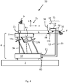
- FIG figure 4 shows schematically an embodiment of a vibratory feeder 50, which is that of FIG figure 2 corresponds, but has a device for automatically tuning the vibration assembly 51.
- a controller 60 of the vibrating conveyor 50 with a control unit 52 which is connected via data lines 53, 54 to a rear sensor 55 for the vertical movement of the rear section 8a and a front sensor 56 for the vertical movement of the free section 8b and a data line 57 with an actuator 58 for the leaf spring 59 is connected.
- the control unit 52 detects the vertical component of the vibrational movement of the carrier arrangement 5 or the rear end of the conveyor chute 6 via the sensor 55 and the vertical component of the vibrational movement of the front end of the conveyor chute 6 via the sensor 56. If these components deviate from each other by a predetermined, in from the threshold value stored in controller 60, control unit 52 generates a correction signal for actuator 58, which thereby slightly retracts (i.e. shortens) or extends (i.e. lengthens) leaf spring 59, see double arrow 62. As a result, the amplitude of the Oscillation of the oscillating arrangement 51.
- the control unit 52 can now process this cycle continuously and thus reduce or prevent a drift in the tuning of the oscillating arrangement 51 and the conveying element 6 due to changing operating conditions. It is also possible for the control unit 52 to correctly tune a vibratory conveyor 50 in operation that is only approximately matched to a specific conveying task, with the control accuracy being able to be set by the predetermined threshold value.
- the sensors 55, 56 can be in the form of simple acceleration sensors, such as those available from TDK InvenSense under the designation MPU-6050.
- other existing data can also be used instead of the data from the rear sensor 55, since the movement of the carrier arrangement 5 is defined - but in any case the vertical movements of the rear section are identical to those of the front section of the conveyor element compared and corrected a deviation by controlling the vibrating assembly 51 until it falls below a predetermined setpoint falls.
- Those skilled in the art can easily determine such a control cycle for the specific case.
- the result is a vibratory conveyor with a front sensor 56 for the vertical movement of the front section 8b of the conveyor element 6 and with a controller 60 which is designed to detect a deviation of the vertical movement of the front section 8b from the vertical movement from the data from the front sensor 56 during operation of the rear section 8a and to generate a correction signal for an actuating arrangement 58 of the vibration arrangement 51 in such a way that the two vertical movements adapt to one another.
- the vibratory conveyor preferably has a rear sensor for the vertical movement of the rear section 8a of the conveyor element. More preferably, the front sensor 56 and particularly preferably the rear sensor 55 is designed as an acceleration sensor.
- the vibrating assembly has two vibrating masses, one on each side of the forward end of the conveyor chute. These can then also be arranged transversely from the conveyor trough protruding leaf springs.
- an oscillating mass on a vertically arranged spiral spring and to arrange an oscillating arrangement designed in this way at the front end of the conveying element. It is also possible to arrange the oscillating mass between two springs. Numerous designs are conceivable for the vibration arrangement according to the invention.
- the oscillating mass can also be arranged on a leaf spring arranged transversely to the conveying element or on a spiral spring arranged vertically. A vertical leaf spring can also be used, in which case the undesired vibration of the front end of section 8b would be corrected by the moment generated in the conveyor chute 6.
Landscapes
- Engineering & Computer Science (AREA)
- Mechanical Engineering (AREA)
- Jigging Conveyors (AREA)
Claims (9)
- Convoyeur vibrant, doté d'une unité d'entraînement (4), générant un mouvement vibratoire en cours de fonctionnement et d'un élément de convoyage (6), placé sur l'unité d'entraînement (4), l'unité d'entraînement (4) comportant un ensemble porteur (5) pour l'élément de convoyage (6), qui par l'intermédiaire d'un segment (8a) arrière est logé sur l'ensemble porteur (5) et qui comporte un segment (8b) s'étendant librement, caractérisé en ce que sur le segment (8b) avant de l'élément de convoyage (6) est prévu un ensemble vibrant (32) résilient, qui est placé et conçu de telle sorte qu'en cours de fonctionnement du convoyeur vibrant, par rapport à la vibration de l'unité d'entraînement (4), il vibre avec un décalage de phase opposé à celui du décalage de phase de l'élément de convoyage (6).
- Convoyeur vibrant selon la revendication 1, les fréquences de résonance de l'élément de convoyage (6) et de l'ensemble vibrant (32) étant différentes de la fréquence de fonctionnement de l'ensemble porteur (4) et par rapport à celle-ci, l'une des fréquences de résonance était plus élevée et l'autre étant plus basse.
- Convoyeur vibrant selon la revendication 1, la fréquence de résonance de l'élément de convoyage étant plus élevée que celle de l'ensemble vibrant (32).
- Convoyeur vibrant selon la revendication 1, l'ensemble vibrant (32) comportant une masse pendulaire (33) et une suspension pendulaire (34) résiliente, par l'intermédiaire de laquelle, il est fixé sur l'élément de convoyage (6).
- Convoyeur vibrant selon la revendication 1, la suspension pendulaire résiliente étant conçue sous la forme de languette (34), qui est placée à la parallèle de la direction de convoyage x de l'élément de convoyage (6) .
- Convoyeur vibrant selon la revendication 4, l'ensemble vibrant résilient comportant deux masses, qui sont placées sur des côtés opposés de l'élément de convoyage.
- Convoyeur vibrant selon la revendication 1, doté d'un capteur (56) avant pour le déplacement vertical du segment (8b) avant de l'élément de convoyage (6) et pourvu d'une unité de réglage (52), qui est conçue pour identifier en cours de fonctionnement à partir des données du capteur (56) avant une divergence entre le déplacement vertical du segment (8b) avant et le déplacement vertical du segment (8a) arrière et pour générer un signal de correction pour un ensemble de réglage (58) de l'ensemble vibrant (51), de telle sorte que les déplacements verticaux s'ajustent l'un à l'autre.
- Convoyeur vibrant selon la revendication 7, celui-ci comportant un capteur (55) arrière pour le déplacement vertical du segment (8a) arrière de l'élément de convoyage (6).
- Convoyeur vibrant selon la revendication 7 ou 8, le capteur (56) avant et de manière particulièrement préférentielle, le capteur (55) arrière étant conçu sous la forme d'un capteur d'accélération.
Applications Claiming Priority (2)
| Application Number | Priority Date | Filing Date | Title |
|---|---|---|---|
| CH00441/18A CH714871A1 (de) | 2018-04-05 | 2018-04-05 | Vibrationsförderer. |
| PCT/IB2019/052268 WO2019193442A1 (fr) | 2018-04-05 | 2019-03-20 | Transporteur à vibrations |
Publications (2)
| Publication Number | Publication Date |
|---|---|
| EP3774603A1 EP3774603A1 (fr) | 2021-02-17 |
| EP3774603B1 true EP3774603B1 (fr) | 2022-06-08 |
Family
ID=62104054
Family Applications (1)
| Application Number | Title | Priority Date | Filing Date |
|---|---|---|---|
| EP19732114.4A Active EP3774603B1 (fr) | 2018-04-05 | 2019-03-20 | Transporteur à vibrations |
Country Status (6)
| Country | Link |
|---|---|
| US (1) | US11198563B2 (fr) |
| EP (1) | EP3774603B1 (fr) |
| JP (1) | JP7220232B2 (fr) |
| CN (1) | CN112218809B (fr) |
| CH (1) | CH714871A1 (fr) |
| WO (1) | WO2019193442A1 (fr) |
Families Citing this family (6)
| Publication number | Priority date | Publication date | Assignee | Title |
|---|---|---|---|---|
| CH713047A1 (de) * | 2016-10-14 | 2018-04-30 | K Tron Tech Inc | Verfahren zur Regelung der Vibrationsbewegung eines Vibrationsförderers und einen Vibrationsförderer. |
| JP7305258B2 (ja) * | 2018-07-18 | 2023-07-10 | 株式会社ディスコ | 搬送システム |
| CN113003169B (zh) * | 2021-02-24 | 2024-11-22 | 美的集团股份有限公司 | 输送装置 |
| DE102021104648B3 (de) * | 2021-02-26 | 2022-02-17 | Trumpf Sachsen Gmbh | Vibrationsförderer zum Fördern eines flächigen Werkstücks in einer Förderrichtung |
| IT202100006770A1 (it) * | 2021-03-22 | 2022-09-22 | Ima Spa | Apparecchiatura vibrante e relativo procedimento per convogliare oggetti. |
| IT202100013355A1 (it) * | 2021-05-24 | 2022-11-24 | Brovind Vibratori S P A | Apparato trasportatore vibrante a due masse e kit di smorzatore di vibrazioni per un apparato trasportatore vibrante a due masse. |
Family Cites Families (16)
| Publication number | Priority date | Publication date | Assignee | Title |
|---|---|---|---|---|
| US2968424A (en) * | 1958-06-30 | 1961-01-17 | Salem Engineering Ltd | Feeding mechanism for interlocking objects |
| JPS4896680U (fr) * | 1972-02-21 | 1973-11-16 | ||
| US4405043A (en) * | 1981-06-12 | 1983-09-20 | Burghart George L | Dynamically balanced vibratory system |
| JPS6056612U (ja) * | 1983-09-28 | 1985-04-20 | 村田精工株式会社 | 直進フイ−ダ |
| JPH0426933U (fr) * | 1990-06-27 | 1992-03-03 | ||
| JPH0595678U (ja) * | 1992-06-04 | 1993-12-27 | 大阪精工株式会社 | 共振振動体の制御装置 |
| DE10312706B4 (de) * | 2003-03-21 | 2005-09-22 | Feintool International Holding | Vibrations-Linearförderer |
| JP4872221B2 (ja) * | 2005-03-11 | 2012-02-08 | シンフォニアテクノロジー株式会社 | 部品搬送装置 |
| GB2426562B (en) * | 2005-05-27 | 2010-04-14 | Wright Machinery Ltd | Vibratory conveyor |
| DE102005051239A1 (de) * | 2005-06-10 | 2006-12-14 | Helmut Krell | Schwingsystem für einen Vibrations-Linearförderer zum Fördern eines Fördergutes und Vibrations-Linearförderer |
| JP4298741B2 (ja) * | 2006-01-17 | 2009-07-22 | ナックフィーディング株式会社 | 振動型搬送装置 |
| JP6163343B2 (ja) * | 2013-04-03 | 2017-07-12 | Ntn株式会社 | 振動式部品搬送装置 |
| JP2016060558A (ja) * | 2014-09-16 | 2016-04-25 | Ntn株式会社 | 振動式部品搬送装置 |
| DE102015212538A1 (de) * | 2015-07-03 | 2017-01-05 | Homag Holzbearbeitungssysteme Gmbh | Transportvorrichtung, insbesondere für Späne und Restteile |
| CH712253A1 (de) * | 2016-03-15 | 2017-09-15 | K-Tron Tech Inc | Vibrationsförderer. |
| CN206782679U (zh) * | 2017-05-06 | 2017-12-22 | 东莞市奥捷自动化设备有限公司 | 一种直线送料器 |
-
2018
- 2018-04-05 CH CH00441/18A patent/CH714871A1/de not_active Application Discontinuation
-
2019
- 2019-03-20 WO PCT/IB2019/052268 patent/WO2019193442A1/fr not_active Ceased
- 2019-03-20 JP JP2020554221A patent/JP7220232B2/ja active Active
- 2019-03-20 EP EP19732114.4A patent/EP3774603B1/fr active Active
- 2019-03-20 CN CN201980024029.4A patent/CN112218809B/zh active Active
- 2019-03-20 US US17/040,224 patent/US11198563B2/en active Active
Also Published As
| Publication number | Publication date |
|---|---|
| US11198563B2 (en) | 2021-12-14 |
| CN112218809A (zh) | 2021-01-12 |
| US20210016973A1 (en) | 2021-01-21 |
| EP3774603A1 (fr) | 2021-02-17 |
| WO2019193442A1 (fr) | 2019-10-10 |
| JP2021520328A (ja) | 2021-08-19 |
| CN112218809B (zh) | 2022-05-13 |
| JP7220232B2 (ja) | 2023-02-09 |
| CH714871A1 (de) | 2019-10-15 |
Similar Documents
| Publication | Publication Date | Title |
|---|---|---|
| CH714871A1 (de) | Vibrationsförderer. | |
| EP3558825B1 (fr) | Magasin à cigarettes conçu pour une machine d'emballage de cigarettes et procédé de fonctionnement correspondant | |
| EP3532410A2 (fr) | Convoyeur à vibrations | |
| DE202016002402U1 (de) | Zuführeinrichtung, Siebeinrichtung und Fördereinrichtung | |
| EP1959244A1 (fr) | Dispositif de dosage doté d'une sonnette | |
| DE102021204377A1 (de) | Verfahren zum Betreiben einer Siebvorrichtung zur Konstanthaltung der Produktqualität bei schwankendem Massestrom | |
| DE10016979C1 (de) | Siebvorrichtung | |
| DE10312706B4 (de) | Vibrations-Linearförderer | |
| DE2255071A1 (de) | Schwingfoerderer | |
| WO2025252879A1 (fr) | Dispositif de transport par vibrations pourvu d'une goulotte de transport et dispositif de dosage pourvu d'un dispositif de transport par vibrations | |
| DE628191C (de) | Vorrichtung zum Absieben | |
| DE2505202A1 (de) | Schwingfoerderer | |
| EP3038961A1 (fr) | Dispositif de dosage pourvu d'un contenant de stockage et d'un dispositif distributeur | |
| AT211222B (de) | Schwingförderer zur Beförderung in einer Richtung | |
| WO2013082727A1 (fr) | Dispositif convoyeur vibrant | |
| EP0578842B1 (fr) | Convoyeur vibrant à déplacement linéaire | |
| DE696032C (fr) | ||
| DE1215050B (de) | Foerderer zum Auf- oder Abwaertstransport von Schuettgut | |
| DE1431600C3 (de) | Vibrationsfördervorrichtung | |
| DE1533505C3 (de) | Vorrichtung zur Steuerung der durch Schwerkraft bedingten Materialbewegung eines schütt- oder fließfähigen Stoffes | |
| DE1078364B (de) | Resonanz-Schwingvorrichtung | |
| EP1281642A1 (fr) | Couloir vibrant avec moteur à pas | |
| DE3002332A1 (de) | Schwingfoerderer | |
| DE202022104174U1 (de) | Dosiervorrichtung und Pulveraufbereitungseinheit für eine Dosiervorrichtung | |
| AT512920B1 (de) | Siebvorrichtung |
Legal Events
| Date | Code | Title | Description |
|---|---|---|---|
| STAA | Information on the status of an ep patent application or granted ep patent |
Free format text: STATUS: UNKNOWN |
|
| STAA | Information on the status of an ep patent application or granted ep patent |
Free format text: STATUS: THE INTERNATIONAL PUBLICATION HAS BEEN MADE |
|
| PUAI | Public reference made under article 153(3) epc to a published international application that has entered the european phase |
Free format text: ORIGINAL CODE: 0009012 |
|
| STAA | Information on the status of an ep patent application or granted ep patent |
Free format text: STATUS: REQUEST FOR EXAMINATION WAS MADE |
|
| 17P | Request for examination filed |
Effective date: 20200930 |
|
| AK | Designated contracting states |
Kind code of ref document: A1 Designated state(s): AL AT BE BG CH CY CZ DE DK EE ES FI FR GB GR HR HU IE IS IT LI LT LU LV MC MK MT NL NO PL PT RO RS SE SI SK SM TR |
|
| AX | Request for extension of the european patent |
Extension state: BA ME |
|
| DAV | Request for validation of the european patent (deleted) | ||
| DAX | Request for extension of the european patent (deleted) | ||
| GRAP | Despatch of communication of intention to grant a patent |
Free format text: ORIGINAL CODE: EPIDOSNIGR1 |
|
| STAA | Information on the status of an ep patent application or granted ep patent |
Free format text: STATUS: GRANT OF PATENT IS INTENDED |
|
| INTG | Intention to grant announced |
Effective date: 20211217 |
|
| GRAS | Grant fee paid |
Free format text: ORIGINAL CODE: EPIDOSNIGR3 |
|
| GRAA | (expected) grant |
Free format text: ORIGINAL CODE: 0009210 |
|
| STAA | Information on the status of an ep patent application or granted ep patent |
Free format text: STATUS: THE PATENT HAS BEEN GRANTED |
|
| AK | Designated contracting states |
Kind code of ref document: B1 Designated state(s): AL AT BE BG CH CY CZ DE DK EE ES FI FR GB GR HR HU IE IS IT LI LT LU LV MC MK MT NL NO PL PT RO RS SE SI SK SM TR |
|
| REG | Reference to a national code |
Ref country code: AT Ref legal event code: REF Ref document number: 1496796 Country of ref document: AT Kind code of ref document: T Effective date: 20220615 Ref country code: CH Ref legal event code: EP |
|
| REG | Reference to a national code |
Ref country code: DE Ref legal event code: R096 Ref document number: 502019004596 Country of ref document: DE |
|
| REG | Reference to a national code |
Ref country code: IE Ref legal event code: FG4D Free format text: LANGUAGE OF EP DOCUMENT: GERMAN |
|
| REG | Reference to a national code |
Ref country code: LT Ref legal event code: MG9D |
|
| REG | Reference to a national code |
Ref country code: NL Ref legal event code: MP Effective date: 20220608 |
|
| PG25 | Lapsed in a contracting state [announced via postgrant information from national office to epo] |
Ref country code: SE Free format text: LAPSE BECAUSE OF FAILURE TO SUBMIT A TRANSLATION OF THE DESCRIPTION OR TO PAY THE FEE WITHIN THE PRESCRIBED TIME-LIMIT Effective date: 20220608 Ref country code: NO Free format text: LAPSE BECAUSE OF FAILURE TO SUBMIT A TRANSLATION OF THE DESCRIPTION OR TO PAY THE FEE WITHIN THE PRESCRIBED TIME-LIMIT Effective date: 20220908 Ref country code: LT Free format text: LAPSE BECAUSE OF FAILURE TO SUBMIT A TRANSLATION OF THE DESCRIPTION OR TO PAY THE FEE WITHIN THE PRESCRIBED TIME-LIMIT Effective date: 20220608 Ref country code: HR Free format text: LAPSE BECAUSE OF FAILURE TO SUBMIT A TRANSLATION OF THE DESCRIPTION OR TO PAY THE FEE WITHIN THE PRESCRIBED TIME-LIMIT Effective date: 20220608 Ref country code: GR Free format text: LAPSE BECAUSE OF FAILURE TO SUBMIT A TRANSLATION OF THE DESCRIPTION OR TO PAY THE FEE WITHIN THE PRESCRIBED TIME-LIMIT Effective date: 20220909 Ref country code: FI Free format text: LAPSE BECAUSE OF FAILURE TO SUBMIT A TRANSLATION OF THE DESCRIPTION OR TO PAY THE FEE WITHIN THE PRESCRIBED TIME-LIMIT Effective date: 20220608 Ref country code: BG Free format text: LAPSE BECAUSE OF FAILURE TO SUBMIT A TRANSLATION OF THE DESCRIPTION OR TO PAY THE FEE WITHIN THE PRESCRIBED TIME-LIMIT Effective date: 20220908 |
|
| PG25 | Lapsed in a contracting state [announced via postgrant information from national office to epo] |
Ref country code: RS Free format text: LAPSE BECAUSE OF FAILURE TO SUBMIT A TRANSLATION OF THE DESCRIPTION OR TO PAY THE FEE WITHIN THE PRESCRIBED TIME-LIMIT Effective date: 20220608 Ref country code: LV Free format text: LAPSE BECAUSE OF FAILURE TO SUBMIT A TRANSLATION OF THE DESCRIPTION OR TO PAY THE FEE WITHIN THE PRESCRIBED TIME-LIMIT Effective date: 20220608 |
|
| PG25 | Lapsed in a contracting state [announced via postgrant information from national office to epo] |
Ref country code: NL Free format text: LAPSE BECAUSE OF FAILURE TO SUBMIT A TRANSLATION OF THE DESCRIPTION OR TO PAY THE FEE WITHIN THE PRESCRIBED TIME-LIMIT Effective date: 20220608 |
|
| PG25 | Lapsed in a contracting state [announced via postgrant information from national office to epo] |
Ref country code: SM Free format text: LAPSE BECAUSE OF FAILURE TO SUBMIT A TRANSLATION OF THE DESCRIPTION OR TO PAY THE FEE WITHIN THE PRESCRIBED TIME-LIMIT Effective date: 20220608 Ref country code: SK Free format text: LAPSE BECAUSE OF FAILURE TO SUBMIT A TRANSLATION OF THE DESCRIPTION OR TO PAY THE FEE WITHIN THE PRESCRIBED TIME-LIMIT Effective date: 20220608 Ref country code: RO Free format text: LAPSE BECAUSE OF FAILURE TO SUBMIT A TRANSLATION OF THE DESCRIPTION OR TO PAY THE FEE WITHIN THE PRESCRIBED TIME-LIMIT Effective date: 20220608 Ref country code: PT Free format text: LAPSE BECAUSE OF FAILURE TO SUBMIT A TRANSLATION OF THE DESCRIPTION OR TO PAY THE FEE WITHIN THE PRESCRIBED TIME-LIMIT Effective date: 20221010 Ref country code: ES Free format text: LAPSE BECAUSE OF FAILURE TO SUBMIT A TRANSLATION OF THE DESCRIPTION OR TO PAY THE FEE WITHIN THE PRESCRIBED TIME-LIMIT Effective date: 20220608 Ref country code: EE Free format text: LAPSE BECAUSE OF FAILURE TO SUBMIT A TRANSLATION OF THE DESCRIPTION OR TO PAY THE FEE WITHIN THE PRESCRIBED TIME-LIMIT Effective date: 20220608 Ref country code: CZ Free format text: LAPSE BECAUSE OF FAILURE TO SUBMIT A TRANSLATION OF THE DESCRIPTION OR TO PAY THE FEE WITHIN THE PRESCRIBED TIME-LIMIT Effective date: 20220608 |
|
| PG25 | Lapsed in a contracting state [announced via postgrant information from national office to epo] |
Ref country code: PL Free format text: LAPSE BECAUSE OF FAILURE TO SUBMIT A TRANSLATION OF THE DESCRIPTION OR TO PAY THE FEE WITHIN THE PRESCRIBED TIME-LIMIT Effective date: 20220608 Ref country code: IS Free format text: LAPSE BECAUSE OF FAILURE TO SUBMIT A TRANSLATION OF THE DESCRIPTION OR TO PAY THE FEE WITHIN THE PRESCRIBED TIME-LIMIT Effective date: 20221008 |
|
| REG | Reference to a national code |
Ref country code: DE Ref legal event code: R097 Ref document number: 502019004596 Country of ref document: DE |
|
| PG25 | Lapsed in a contracting state [announced via postgrant information from national office to epo] |
Ref country code: AL Free format text: LAPSE BECAUSE OF FAILURE TO SUBMIT A TRANSLATION OF THE DESCRIPTION OR TO PAY THE FEE WITHIN THE PRESCRIBED TIME-LIMIT Effective date: 20220608 |
|
| PLBE | No opposition filed within time limit |
Free format text: ORIGINAL CODE: 0009261 |
|
| STAA | Information on the status of an ep patent application or granted ep patent |
Free format text: STATUS: NO OPPOSITION FILED WITHIN TIME LIMIT |
|
| PG25 | Lapsed in a contracting state [announced via postgrant information from national office to epo] |
Ref country code: DK Free format text: LAPSE BECAUSE OF FAILURE TO SUBMIT A TRANSLATION OF THE DESCRIPTION OR TO PAY THE FEE WITHIN THE PRESCRIBED TIME-LIMIT Effective date: 20220608 |
|
| 26N | No opposition filed |
Effective date: 20230310 |
|
| PG25 | Lapsed in a contracting state [announced via postgrant information from national office to epo] |
Ref country code: SI Free format text: LAPSE BECAUSE OF FAILURE TO SUBMIT A TRANSLATION OF THE DESCRIPTION OR TO PAY THE FEE WITHIN THE PRESCRIBED TIME-LIMIT Effective date: 20220608 |
|
| PG25 | Lapsed in a contracting state [announced via postgrant information from national office to epo] |
Ref country code: MC Free format text: LAPSE BECAUSE OF FAILURE TO SUBMIT A TRANSLATION OF THE DESCRIPTION OR TO PAY THE FEE WITHIN THE PRESCRIBED TIME-LIMIT Effective date: 20220608 |
|
| REG | Reference to a national code |
Ref country code: BE Ref legal event code: MM Effective date: 20230331 |
|
| PG25 | Lapsed in a contracting state [announced via postgrant information from national office to epo] |
Ref country code: LU Free format text: LAPSE BECAUSE OF NON-PAYMENT OF DUE FEES Effective date: 20230320 |
|
| REG | Reference to a national code |
Ref country code: IE Ref legal event code: MM4A |
|
| PG25 | Lapsed in a contracting state [announced via postgrant information from national office to epo] |
Ref country code: IE Free format text: LAPSE BECAUSE OF NON-PAYMENT OF DUE FEES Effective date: 20230320 |
|
| PG25 | Lapsed in a contracting state [announced via postgrant information from national office to epo] |
Ref country code: BE Free format text: LAPSE BECAUSE OF NON-PAYMENT OF DUE FEES Effective date: 20230331 |
|
| PG25 | Lapsed in a contracting state [announced via postgrant information from national office to epo] |
Ref country code: BG Free format text: LAPSE BECAUSE OF FAILURE TO SUBMIT A TRANSLATION OF THE DESCRIPTION OR TO PAY THE FEE WITHIN THE PRESCRIBED TIME-LIMIT Effective date: 20220608 |
|
| PG25 | Lapsed in a contracting state [announced via postgrant information from national office to epo] |
Ref country code: BG Free format text: LAPSE BECAUSE OF FAILURE TO SUBMIT A TRANSLATION OF THE DESCRIPTION OR TO PAY THE FEE WITHIN THE PRESCRIBED TIME-LIMIT Effective date: 20220608 |
|
| REG | Reference to a national code |
Ref country code: AT Ref legal event code: MM01 Ref document number: 1496796 Country of ref document: AT Kind code of ref document: T Effective date: 20240320 |
|
| PG25 | Lapsed in a contracting state [announced via postgrant information from national office to epo] |
Ref country code: AT Free format text: LAPSE BECAUSE OF NON-PAYMENT OF DUE FEES Effective date: 20240320 |
|
| PG25 | Lapsed in a contracting state [announced via postgrant information from national office to epo] |
Ref country code: CY Free format text: LAPSE BECAUSE OF FAILURE TO SUBMIT A TRANSLATION OF THE DESCRIPTION OR TO PAY THE FEE WITHIN THE PRESCRIBED TIME-LIMIT; INVALID AB INITIO Effective date: 20190320 |
|
| PG25 | Lapsed in a contracting state [announced via postgrant information from national office to epo] |
Ref country code: HU Free format text: LAPSE BECAUSE OF FAILURE TO SUBMIT A TRANSLATION OF THE DESCRIPTION OR TO PAY THE FEE WITHIN THE PRESCRIBED TIME-LIMIT; INVALID AB INITIO Effective date: 20190320 |
|
| PG25 | Lapsed in a contracting state [announced via postgrant information from national office to epo] |
Ref country code: TR Free format text: LAPSE BECAUSE OF FAILURE TO SUBMIT A TRANSLATION OF THE DESCRIPTION OR TO PAY THE FEE WITHIN THE PRESCRIBED TIME-LIMIT Effective date: 20220608 |
|
| REG | Reference to a national code |
Ref country code: CH Ref legal event code: U11 Free format text: ST27 STATUS EVENT CODE: U-0-0-U10-U11 (AS PROVIDED BY THE NATIONAL OFFICE) Effective date: 20260401 |
|
| PGFP | Annual fee paid to national office [announced via postgrant information from national office to epo] |
Ref country code: GB Payment date: 20260317 Year of fee payment: 8 |
|
| PGFP | Annual fee paid to national office [announced via postgrant information from national office to epo] |
Ref country code: DE Payment date: 20260320 Year of fee payment: 8 |
|
| PGFP | Annual fee paid to national office [announced via postgrant information from national office to epo] |
Ref country code: AT Payment date: 20260410 Year of fee payment: 5 |
|
| PGFP | Annual fee paid to national office [announced via postgrant information from national office to epo] |
Ref country code: FR Payment date: 20260324 Year of fee payment: 8 |
|
| PGFP | Annual fee paid to national office [announced via postgrant information from national office to epo] |
Ref country code: IT Payment date: 20260331 Year of fee payment: 8 |
|
| PGFP | Annual fee paid to national office [announced via postgrant information from national office to epo] |
Ref country code: CH Payment date: 20260401 Year of fee payment: 8 |