EP3775410B1 - Verschleissteil, rand und verfahren zur montage - Google Patents
Verschleissteil, rand und verfahren zur montage Download PDFInfo
- Publication number
- EP3775410B1 EP3775410B1 EP19775785.9A EP19775785A EP3775410B1 EP 3775410 B1 EP3775410 B1 EP 3775410B1 EP 19775785 A EP19775785 A EP 19775785A EP 3775410 B1 EP3775410 B1 EP 3775410B1
- Authority
- EP
- European Patent Office
- Prior art keywords
- shroud
- boss
- lip
- bearing surfaces
- recess
- Prior art date
- Legal status (The legal status is an assumption and is not a legal conclusion. Google has not performed a legal analysis and makes no representation as to the accuracy of the status listed.)
- Active
Links
Images


Classifications
-
- E—FIXED CONSTRUCTIONS
- E02—HYDRAULIC ENGINEERING; FOUNDATIONS; SOIL SHIFTING
- E02F—DREDGING; SOIL-SHIFTING
- E02F9/00—Component parts of dredgers or soil-shifting machines, not restricted to one of the kinds covered by groups E02F3/00 - E02F7/00
- E02F9/28—Small metalwork for digging elements, e.g. teeth scraper bits
- E02F9/2883—Wear elements for buckets or implements in general
-
- E—FIXED CONSTRUCTIONS
- E02—HYDRAULIC ENGINEERING; FOUNDATIONS; SOIL SHIFTING
- E02F—DREDGING; SOIL-SHIFTING
- E02F3/00—Dredgers; Soil-shifting machines
- E02F3/04—Dredgers; Soil-shifting machines mechanically-driven
- E02F3/28—Dredgers; Soil-shifting machines mechanically-driven with digging tools mounted on a dipper- or bucket-arm, i.e. there is either one arm or a pair of arms, e.g. dippers, buckets
- E02F3/36—Component parts
- E02F3/40—Dippers; Buckets ; Grab devices, e.g. manufacturing processes for buckets, form, geometry or material of buckets
-
- E—FIXED CONSTRUCTIONS
- E02—HYDRAULIC ENGINEERING; FOUNDATIONS; SOIL SHIFTING
- E02F—DREDGING; SOIL-SHIFTING
- E02F3/00—Dredgers; Soil-shifting machines
- E02F3/04—Dredgers; Soil-shifting machines mechanically-driven
- E02F3/46—Dredgers; Soil-shifting machines mechanically-driven with reciprocating digging or scraping elements moved by cables or hoisting ropes ; Drives or control devices therefor
- E02F3/58—Component parts
- E02F3/60—Buckets, scrapers, or other digging elements
-
- E—FIXED CONSTRUCTIONS
- E02—HYDRAULIC ENGINEERING; FOUNDATIONS; SOIL SHIFTING
- E02F—DREDGING; SOIL-SHIFTING
- E02F3/00—Dredgers; Soil-shifting machines
- E02F3/04—Dredgers; Soil-shifting machines mechanically-driven
- E02F3/76—Graders, bulldozers, or the like with scraper plates or ploughshare-like elements; Levelling scarifying devices
- E02F3/80—Component parts
- E02F3/815—Blades; Levelling or scarifying tools
- E02F3/8152—Attachments therefor, e.g. wear resisting parts, cutting edges
-
- E—FIXED CONSTRUCTIONS
- E02—HYDRAULIC ENGINEERING; FOUNDATIONS; SOIL SHIFTING
- E02F—DREDGING; SOIL-SHIFTING
- E02F9/00—Component parts of dredgers or soil-shifting machines, not restricted to one of the kinds covered by groups E02F3/00 - E02F7/00
- E02F9/24—Safety devices, e.g. for preventing overload
-
- E—FIXED CONSTRUCTIONS
- E02—HYDRAULIC ENGINEERING; FOUNDATIONS; SOIL SHIFTING
- E02F—DREDGING; SOIL-SHIFTING
- E02F9/00—Component parts of dredgers or soil-shifting machines, not restricted to one of the kinds covered by groups E02F3/00 - E02F7/00
- E02F9/28—Small metalwork for digging elements, e.g. teeth scraper bits
- E02F9/2808—Teeth
- E02F9/2816—Mountings therefor
- E02F9/2833—Retaining means, e.g. pins
-
- E—FIXED CONSTRUCTIONS
- E02—HYDRAULIC ENGINEERING; FOUNDATIONS; SOIL SHIFTING
- E02F—DREDGING; SOIL-SHIFTING
- E02F9/00—Component parts of dredgers or soil-shifting machines, not restricted to one of the kinds covered by groups E02F3/00 - E02F7/00
- E02F9/28—Small metalwork for digging elements, e.g. teeth scraper bits
- E02F9/2891—Tools for assembling or disassembling
-
- E—FIXED CONSTRUCTIONS
- E02—HYDRAULIC ENGINEERING; FOUNDATIONS; SOIL SHIFTING
- E02F—DREDGING; SOIL-SHIFTING
- E02F9/00—Component parts of dredgers or soil-shifting machines, not restricted to one of the kinds covered by groups E02F3/00 - E02F7/00
- E02F9/28—Small metalwork for digging elements, e.g. teeth scraper bits
- E02F9/2808—Teeth
- E02F9/2858—Teeth characterised by shape
Definitions
- the field of the present disclosure relates to wear members for earth working equipment.
- replaceable wear members are typically used to protect earth working equipment such as excavation buckets. During use, the wear members gradually wear down due to the abrasive conditions and heavy loading. Once depleted, the wear members are removed from the equipment and replaced. Using wear members provides a cost-effective approach to digging and other earth working operations because it lessens the need of having to repair or replace the more expensive underlying equipment such as the lip or other portions of the equipment.
- Wear members are commonly secured to earth working equipment by mechanical means (for example, a lock pin, bolt, or other locking mechanism). During earth working operations, wear members may be subjected to a variety of directional forces, which can include axial, vertical, and lateral loads. Retention of the wear members over their service life prevents damage to downstream equipment such as crushers, limits maintenance downtime of the earthmoving equipment and prevents damage to underlying wear surfaces.
- mechanical means for example, a lock pin, bolt, or other locking mechanism.
- the present invention pertains to a shroud for covering an earth-working edge on earth working equipment which includes a front end and a rearwardly-opening cavity.
- the cavity has opposed first and second surfaces to straddle the edge and a front surface extending between the first and second surfaces.
- the first surface includes a recess with opposed planar bearing surfaces to bear against a boss on the edge. These bearing surfaces converge toward the front surface.
- a similar shroud is taught by EP 2 913 446 A1 .
- the instant invention relates to a shroud for an earth-working edge on earth-working equipment according to claim 1.
- the shroud of the invention is reliable, safe, easy to use, versatile, given to high productivity and/or readily replaceable with little machine downtime.
- one of the first bearing surfaces is parallel to the second bearing surfaces and the other first bearing surface is transverse to the second bearing surfaces.
- a lip assembly for an earth working bucket includes a lip and a shroud as defined in claim 8.
- the lip has a forward-facing leading surface, primary segments where the leading surface extends parallel to the width of the bucket, and transition segments where the leading surface is inclined to the primary segments.
- the shroud is secured to a transition segment.
- the instant invention relates to a process for installing a shroud on an earth-working edge on earth working equipment according to independent claim 9.
- Wear members are applied to many kinds of earth working equipment to extend the service life of the equipment.
- the present invention is related to wear members and locking systems for securing the wear members to edges of earth working equipment, wear assemblies involving the same, edges of earth working equipment, and processes for installing wear members on such edges.
- the figures show one embodiment of a wear assembly 10 including a wear member 12 for attachment to earth working equipment.
- the wear member is a shroud 12 attached to an edge of an earthmoving bucket; the edge as shown is defined by a lip 14 having an elongate body with a bottom or outer surface 14A, a top or inner surface 14B and a leading surface 14C.
- inner surface 14B includes a beveled portion or surface 14D adjacent leading surface 14C, and a rear portion rearward of the beveled portion.
- Shrouds in accordance with the invention may also be secured to the sidewalls of the bucket, ripper shanks, and/or other edges of earth working equipment; that is, shrouds 12 can be used in connection with a variety of different earth working components having earth working edges including, for example, buckets, lips, ripper shanks and the like.
- the wear member 12 preferably includes an opening 24 that receives a lock 16 to releasably secure the wear member to the edge.
- the edge can have a variety of different designs including those with a linear leading surface, or a leading surface that is stepped or swept such that the center portion is forward or rearward relative to outer portions of the edge.
- the edge has a direction of advance during operation of the earth working equipment (e.g., a digging operation) that is generally in the direction to arrow 6 ( Figs. 12 and 13 ); this is referred to as the forward direction herein.
- the actual movement of the edge during operation can be a generally linear advance (such as, e.g., with a dragline bucket or ripper shank) or a compound motion with a swinging movement (such as, e.g., with a hydraulic excavator).
- each tooth 7 includes an adapter 8 with rearward extending legs that are welded to the top and bottom surfaces of the lip or secured by mechanical means.
- the adapter includes a forwardly projecting nose 9 onto which is received a point 8A that is secured to the adapter by a lock (not shown).
- Shrouds 12 are secured to lip 14 in between adjacent teeth 7.
- the lip may include only shrouds such as in an LHD bucket.
- the lip can be formed by a casting process, or the lip can be cut from plate.
- the lip can also be welded together from separately formed sections.
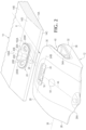
- the shroud 12 includes a front end or working portion 26 and a rear end or mounting portion 28 ( Figs. 1-7 ).
- the working portion tapers to a narrowed front working edge 26A but other constructions are possible.
- the mounting portion 28 includes a first leg 30, which in the illustrated embodiment is an inner or top leg 30, and an opposite second leg 32, which is an outer or bottom leg 32.
- the legs 30, 32 are spaced to define a cavity 40 to receive the lip 14 such that each leg extends rearward along the lip when the shroud is installed.
- a front surface or end wall 42 joins the first and second legs at the front end of cavity 40.
- the first leg 30 has an interior surface 33 that forms a first or inner surface of cavity 40, and which can include one or more first or inner bearing surfaces 34 that bear against the inner or top surface of the lip when assembled ( Figs. 5 and 7 ).
- the first bearing surfaces in this example are formed as raised bearing pads 34A, 34B, though they need not be so formed; the interior surface 33 itself could form the bearing surface or there could be other arrangements.
- the inner bearing surfaces bear on the beveled edge 14D of the lip.
- the forward bearing surfaces 34A are inclined to the rear bearing surfaces 34B such that bearing surfaces 34A bear against the front bevel surface 14D of the lip while bearing surfaces 34B bear against the inner or top surface 14B of the lip.
- the first leg also includes a rear surface 30A.
- the second or outer leg 32 includes an interior surface 35 that defines a second or outer surface of cavity 40.
- Interior surface 35 can include one or more second or outer bearing surfaces 36 to bear against the generally planar outer or bottom surface 14A of the lip ( Fig. 6 ).
- second bearing surfaces 36 are formed as raised bearing pads, but they need not be; the interior surface 35 itself could define the bearing surface or there could be another arrangement.
- the second leg includes a rear surface 32A ( Figs. 5 and 7 ).
- the front surface 42 extends between and joins legs 30, 32. Front surface 42 is adjacent to or bears against the leading or front surface 14C of the lip 14 when the shroud is fully installed on the lip. Opening 24 extends through the first leg 30 and opens to cavity 40 to receive a lock 16. Other arrangements for securing the wear member are possible. Other variations in the wear member 12 are also possible. For example, the cavity of the wear member is shaped to correspond to the configuration of edge 14, and could have varied shapes to complement different edges.
- Each shroud 12 has a longitudinal axis 44 that is defined by a centerline extending generally in the direction of advancement of the edge 14 during operation of the earth working equipment ( Figs. 2 and 4 ).
- a datum line 38 extends along the front surface 42 and corresponds to the leading surface 14C when the shroud is installed. While the front of cavity 40 (i.e., along front surface 42) could have various configurations (such as including recesses), the front surface 42 is that portion of the front of the cavity that extends generally parallel to the leading edge it is designed to oppose.
- the first leg 30 preferably includes a first or clearance recess 48 in interior surface 33 that extends forward from rear leg surface 30A ( Figs. 6 and 7 ).
- a first supporting recess 50 that extends at a greater depth from the interior surface 33 than first recess 48.
- Recess 50 includes bearing surfaces 50A and 50B that converge in a forward direction, i.e., toward front surface 42.
- bearing surfaces 50A, 50B extend forward of opening 24 but other arrangements are possible.
- Bearing surfaces 50A, 50B can be planar, but other surface shapes are possible such as curved converging surfaces.
- a first recess axis 100 extends centrally between bearing surfaces 50A, 50B, and perpendicular to front surface 42.
- a rear recess 50C extends between rear leg surface 30A and opening 24 in general alignment with supporting recess 50, though in this example with a different extension (which is not necessary). Although recesses 50, 50C are discussed herein as separate recesses separated by opening 24, they could be considered as a single recess with front and rear portions.
- Rear recess axis 52 extends as a centerline of rear recess 50C and is generally parallel to the longitudinal axis 44 of shroud 12. Other alternatives are possible.
- the first leg may only have a supporting recess 50 without the rear recess 50C provided sufficient clearance exists to receive the corresponding boss 20.
- bearing surfaces 50A, 50B could project from interior surface 33 to form recess 50 rather than be formed within a depression in the interior surface.
- Bearing surfaces 50A, 50B could also alternatively be formed in second leg 32 with a corresponding shift of the boss 20 it receives to the opposite surface 14A of edge 14.
- the rear recess axis 52 can be generally parallel to recess axis 100. Other arrangements are possible.
- the lip 14 includes a first or inner boss 20 on the bevel 14D of an inner or upper surface 14B of the lip ( Figs. 2 and 3 ). Nevertheless, boss 20 could be rearward of bevel 14D or used on a lip without a bevel.
- the first boss includes side bearing surfaces 20A and 20B ( Figs. 2 , 8 and 9 ) against which bearing surfaces 50A, 50B bear, and a rear bearing surface 20E against which lock 16 bears when shroud 12 is installed on lip 14; though other locks that bear on other surfaces are possible.
- the first boss 20 can include a base with a mounting surface 20F that sets against the edge.
- the base may include mounting wings 20W, though other mounting arrangements are possible. As one example, the wings could be omitted.
- the side bearing surfaces 20A and 20B can be formed on a lug 20D extending upward from the base.
- the rear bearing surface 20E extends transversely between side bearing surfaces 20A and 20B and faces generally rearward to abut lock 16.
- the side bearing surfaces 20A, 20B of the boss 20 are preferably planar and converge in a forward direction from transverse bearing surface 20E.
- Side bearing surfaces 20A and 20B can, for example, converge forward at an angle of 10-40 degrees to each other. Preferably, the side bearing surfaces converge forward at an angle of 15-30 degrees to each other. The convergence of bearing surfaces 20A, 20B, though, could be outside these ranges.
- Bearing surfaces 50A, 50B also preferably have the same angular orientation as side bearing surfaces 20A, 20B.
- Boss 20 has a first boss axis 100A defined by the centerline between side bearing surfaces 20A, 20B.
- Boss axis 100A is generally perpendicular to the leading surface 14C of the lip that is closest to where boss 20 is fixed.
- Boss 20 can be attached to the lip by welding or other attachment means (e.g., bolts), machined in the lip or as cast configuration of the lip.
- cavity 40 receives lip 14 as the shroud moves rearward.
- Installing shroud 12 in a direction parallel to the direction of advance of the lip limits interference with adjacent teeth and/or noses secured to or forming part of the lip. This arrangement permits removal and/or installation of the shrouds without the need to remove points and/or adapters of adjacent teeth.
- Supporting recess 50 receives boss 20 such that bearing surfaces 50A, 50B oppose bearing surfaces 20A, 20B when shroud 12 is installed on lip 14.
- First recess 48 and rear recess 50C provide clearance for receiving boss 20 in recess 50, and/or for the boss mounting wings 20W or other mounting arrangement.
- Opening 24 includes a bearing wall 24A to bear against a rear side of lock 16. The opposite front side of the lock bears on bearing surface 20E of first boss 20. Longitudinal forces on the shroud that urge the shroud off the lip are countered as the lock bears on the bearing wall 24A and bearing surface 20E to secure the shroud on the lip 14. Opening 24 is preferably elongate and defines a major axis 24B along its length, though other opening shapes are possible.
- Opening axis 24B is preferably parallel to front surface 42, though opening axis 24B may be inclined or perpendicular to the longitudinal axis 44 of the shroud. In one example, opening axis 24B is angled relative to longitudinal axis 44 between 65 to 90 degrees, though orientations outside this range are possible.
- the orientation of the lock opening i.e., the opening axis 24B
- lock 16 can include two portions that fold between an extended position that has a length that is longer than opening 24 (along major axis 24B) in exterior surface 45 of first leg 30 to prevent loss or removal of the lock from the wear member, and a folded position with a length that is shorter than opening 24 to permit release and/or removal of the lock from the opening, which may be when the shroud is installed on and/or removed from the lip.
- the lock can be of the kinds such as disclosed in US Patent 7536811 or US Patent Application 2017/0321396 .
- Other lock configurations for securing the shroud to the lip are possible; various hammerless and hammered locks can be used.
- bearing surfaces 50A and 50B of the supporting recess 50 bear on boss surfaces 20A and 20B to transfer loads to the lip.
- Mounting the first boss to the beveled portion of the lip allows the shroud to be mounted to certain lips of differing thicknesses. This enables the manufacture and/or stocking of fewer shroud sizes.
- Securing boss 20 to the bevel surface 14D can also enable the shroud to have a lower weight, a slimmer profile for easier penetration and/or less blocking of material in and out of the bucket.
- a boss 20 is only provided on one surface of the lip, which in this example is on the inner side 14B and specifically on ramp 14D, though the one boss could be provided rearward of ramp 14D or on outer side 14A.
- boss 20 could have a forward extension that overlies leading surface 14C.
- the second leg 32 of shroud 12 includes a second supporting recess 46 in interior surface 35 that extends forward from back wall 32A to receive a second or outer boss 22.
- Recess 46 includes side bearing surfaces 46A and 46B and, optionally, a chin recess 46C further recessed from interior surface 35.
- the recess 46 has a second recess axis 102 defined by a centerline between side bearing surfaces 46A, 46B, and which is generally parallel to longitudinal axis 44 of shroud 12.
- the chin recess 46C can be defined by a ramp surface 46D inclined to interior surface 35.
- the chin recess can optionally also or in lieu of include a base surface 46E generally parallel to the interior surface 35 forward of ramp surface 46D. Other configurations of a chin recess are possible.
- the lip includes a second or outer boss 22 on the lower surface 14A of the lip.
- the second boss includes side bearing surfaces 22A and 22B, and optionally a chin 22E that extends outward from the lip in a forward direction ( Figs. 10 and 11 ).
- Side bearing surfaces 22A and 22B can be parallel to each other. Alternatively, the side bearing surfaces can converge in a forward direction. Other configurations are possible.
- Boss 22 includes a mounting surface 22F that sets against the lip and an opposite outer surface 22D. Boss 22 can be attached to the lip by welding or by other attachment means (e.g., bolts).
- Boss 22 includes a second boss axis 102A defined by a centerline between bearing surfaces 22A, 22B, which will be generally parallel to the direction of lip advancement shown by arrow 6.
- cavity 40 receives lip 14 as the shroud moves rearward in relation to the lip along a direction opposite of arrow 6.
- First recess 50 receives first boss 20 and second recess 46 receives second boss 22.
- the side bearing surfaces 50A and 50B of first supporting recess 50 oppose bearing surfaces 20A and 20B of the first boss 20, and side bearing surfaces 46A and 46B of second supporting recess 46 oppose side bearing surfaces 22A and 22B of second boss 22.
- chin 22E is received in chin recess 46C
- lock 16 is received in opening 24 to secure the shroud to the lip as previously described.
- bearing surfaces 50A and 50B of recess 50 bear on the bearing surfaces 20A and 20B of boss 20 to transfer loads applied to the shroud during earth working operations to the lip.
- Bearing surfaces 46A and 46B of recess 46 also bear on bearing surfaces 22A and 22B of boss 22 to transfer loads to the lip. Applied loads are transferred from the shroud to the lip through the bosses and bearing surfaces to limit wear to the lip. Applied loads are also transferred through the legs of the boss to the edge.
- the chin and the chin recess include inclined surfaces to resist reverse forces on the shroud urging the shroud off the lip, and thereby reduce such forces acting on the lock; as noted above, the chin and chin recess could be omitted.
- the use of a top boss only or the use of separate top and bottom bosses allow the same shroud to be mounted to lips of different thicknesses, which can reduce the number of different kinds and/or sizes of shrouds that need to be made or kept in inventory.
- the bosses are welded to the lip.
- one or both bosses can be integral with the lip; for example, the bosses could be included as part of a cast lip.
- one or both bosses could be formed by adding welding material to the lip or by other means.
- Fig. 12 shows an exploded top view of lip 14 with shrouds 12 and teeth 7.
- the lip is stepped or swept so the center of the lip extends farther forward than the outer portions.
- the center portion could extend farther rearward than the outer portions.
- lip 14 includes a plurality of spaced apart stepped segments 60 where the leading edge 14C of the lip extends generally perpendicular to the advance of the lip along arrow 6, and a plurality of transition segments 62 interconnecting adjacent step segments 60.
- lip 14 includes a central step segment 60A and an outer step segment 60B, 60C to each side of the central step segment 60A. Additional outer step and transition segments could and would usually also be included outside step segments 60B, 60C (not shown).
- Each step segment 60 could be identical or there could be differences.
- the leading edges 14C of transition segments 62 are inclined to the leading edges 14C of step segments 60; the angle of inclination ⁇ is commonly less than 22°, but other configurations are possible.
- Straight lips have a linear leading edge across the width of the bucket and, thus, will have zero angle of inclination on the transition segments extending between adjacent teeth. With a straight plate lip, there may be no differences between step and transition segments.
- Transition segments 62L, 62R to each side of central step segment 60A are preferably mirror images of each other, with transition segment 62L inclined in one direction and transition segment 62R inclined in the opposition direction, but all preferably at the same angle of inclination.
- two teeth 7 are secured to each step segment, and a shroud 12 is secured between each pair of adjacent teeth 7. Accordingly, shrouds 12 are secured to both step segments and transition segments. Nevertheless, various other configurations are possible. As one example alternative, one tooth could be secured to each step segment and a shroud secured to each transition segment.
- Bosses 20 are secured to each segment 60, 62 that mounts a shroud 12.
- the lip includes a left boss 20L on a left transition segment 62L, a center boss 20C on center step segment 60A, and a right boss 20R on a right transition segment 62R; left and right used herein is solely for ease of explanation based on the view in Fig. 12 .
- a left shroud 12L is shown to mount to boss 20L.
- a center shroud 12C is shown to mount to boss 20C.
- a right shroud 12R is shown to mount to boss 20R. While bosses 20 all preferably have the same construction, they are each secured at different orientations on the lip.
- Left and right shrouds are inclined in opposite directions to correspond to the inclination of the leading surfaces of transition segments 62 to which each attach.
- the boss axis 100A for each first boss 20 is generally perpendicular to the leading edge 14C of the step or transition segment 60, 62 to which it is secured, and generally perpendicular to the front surface 42 of the shroud 12 mounted over it.
- datum lines 38L, 38C, 38R show the orientation of the front surfaces 42 of the three different shrouds 12L, 12C, 12R. As can be seen, front surfaces 42 of left and right shrouds 12L, 12R are inclined to the advance direction 6 of lip 14.
- front surfaces 42 correspond to leading edge 14C of the different lip segments 60, 62
- front surfaces 42 of left and right shrouds 12L, 12R are preferably inclined more than 80 ° to the direction of advance of the lip (i.e., arrow 6); though other orientations are possible.
- the front surface 42 of center shroud 12C will be generally perpendicular to the direction of lip advancement (i.e., arrow 6), and perpendicular to boss axis 100A of center boss 20C.
- Some lips can include only left shrouds and right shrouds with no center shrouds. Alternatively, a straight lip with no inclination will include only center shrouds.
- Fig. 13 shows an exploded bottom view of lip 14 with shrouds 12 and teeth 7.
- the bottom surface 14A of the lip includes bosses 22 secured to each lip segment 60, 62 to which a shroud is secured.
- boss 22L is secured to transition segment 62L
- boss 22C is secured to primary or step segment 60A
- boss 22R is secured to transition segment 62R.
- Each of the second bosses 22 preferably have the same construction, and the same orientation, i.e., such that second boss axes 102A are each generally parallel to the direction of lip advancement (i.e., line 6).
- Fig. 13 shows shroud 12L about to be installed on transition segment 62L of lip 14.
- First boss 20 will be received in first supporting recess 50
- second boss 22 will be received in second supporting recess 46.
- the boss axes 100A, 102A are angularly oriented to each other ( Figs. 2 , 12 and 13 ) in a lateral direction (i.e., in a side-to-side direction and not with respect to axial or vertical directions).
- the second recess axis 102 is parallel to and aligned with second boss axis 102A. The receipt of boss 22 into recess 46, then, controls the installation movement of shroud 12.
- bearing surfaces 20A, 20B and 50A, 50B are angled to resist the rearward and side loads applied to shrouds.
- shroud 12 is secured to a transition segment 62, recess axis 100 and boss axis 100A are inclined to the direction of lip advancement.
- bearing surface 20A of first boss 20 is generally aligned with bearing surface 22A of second boss 22.
- bearing surface 50A will move parallel to bearing surface 20A
- bearing surface 46A will move parallel to bearing surface 22A
- bearing surface 46B will move parallel to bearing surface 22B.
- bearing surface 50B will move toward bearing surface 20B until they meet in opposition to each other when shroud 12L is fully seated on lip 14.
- Clearance recess 48 and rear recess 50C enable boss 20 to be pass into a fully seated position against bearing surfaces 50A, 50B on shroud 12.
- Other shaped recesses or other constructions could be used to provide the needed clearance. Removal of shroud 12L will be the reverse of the installation.
- the installation of right shrouds 12R would be the mirror image of the installation of shrouds 12L.
- bearing surface 50B of first supporting recess 50 will move parallel to bearing surface 20B of first boss 20B, while bearing surfaces 46A, 46B move parallel to bearing surfaces 22A, 22B.
- Bearing surface 50A during installation will move toward and then meet bearing surface 20A when the shroud is fully seated. Removal of shroud 12R will be the reverse of the installation.
- Shroud 12 can optionally include an opening 54 that receives a mechanically attached lifting eye 56 such as disclosed in US Patent Application 2015/0013134 .
- a cast-in eye (not shown), one or more eyes in other locations, or no eye could be used.
- the first boss 20 can include strain relief 20G between the side bearing surfaces and the boss wings 20W ( Fig. 8A ).
- the boss wings can be welded to the lip and the middle portion of the boss (i.e., the portion between boss wings 20W and supporting boss lug 20D) remains without being rigidly secured to the lip.
- Strain reliefs such as cutouts of the boss material or a section of material with different material properties can be incorporated between the boss lug and the wings. Loads applied to the boss will, then, cause the boss lug to deflect. The loads may be partially absorbed at the strain reliefs at the sides of the boss lug to spread the load more evenly over the wing welds. This limits stress concentrations that can result in cracking at the welds.
- Other kinds of strain relief such as disclosed in US Patent 8925220 , by could also be used.
- Opening 24 can optionally be configured with two positions for lock 16 ( Figs. 14 and 14A ), a locking position and a release position, such as disclosed in US Patent Application 2017/0321396 ..
- the wear assembly provides support for the wear member during operation. Forces applied to the wear member 12 can cause the wear member to shift and bear on the leading surface 14C, converging faces 20A, 20B of the first boss 20, the side bearing surfaces 22A, 22B of the second boss 22 and/or the outer and inner surfaces 14A, 14B. Bottom and/or reverse loads can be resisted in part through chin 22E and recess 46C if a chin is provided. The loads applied to the bosses are transferred through the bosses to the lip. The first boss 20 can be attached to the beveled front surface of the lip.
- the wear assembly can provide reduced weight and/or profile and/or efficient replacement of worn wear members, and/or can reduce downtime and/or operating expenses for earth working equipment.
- Shrouds in accordance with the present invention may have other constructions for use on a wide variety of buckets including, for example, buckets for hydraulic excavators, loaders, cable shovels, face shovels, etc., or for use on other products such as ripper shanks.
- the wear members may be secured to a lip, to a base secured to the lip, to other portions of a bucket, or to other earth working equipment. Relative terms such as top, bottom, forward, rearward, left and right are used herein for ease of discussion and are not intended to be limiting.
Landscapes
- Engineering & Computer Science (AREA)
- Mining & Mineral Resources (AREA)
- Civil Engineering (AREA)
- General Engineering & Computer Science (AREA)
- Structural Engineering (AREA)
- Mechanical Engineering (AREA)
- Component Parts Of Construction Machinery (AREA)
- Soil Working Implements (AREA)
- Sliding Valves (AREA)
- Laying Of Electric Cables Or Lines Outside (AREA)
Claims (9)
- Eine Schutzabdeckung (12) für eine Erdarbeitskante (14) an Erdarbeitseinrichtung, umfassend ein vorderes Ende (26) und einen nach hinten öffnenden Hohlraum (40) einschließlich gegenüberliegender erster (33) und zweiter (35) Flächen zum Umschließen der Kante und einer vorderen Fläche (42), die sich zwischen der ersten und zweiten Fläche erstreckt, wobei die erste Fläche (33) eine Vertiefung (50) mit einer ersten Längsachse (100) und gegenüberliegenden ebenen Auflageflächen (50A, 50B) umfasst, die gegen eine erste Erhebung (20) an der Kante (14) aufliegen, wobei die Auflageflächen (50A, 50B) zur vorderen Fläche (42) hin zusammenlaufen, und wobei die zweite Fläche (35) eine Vertiefung (46) mit einer zweiten Längsachse (102) und gegenüberliegenden ebenen Auflageflächen (46A, 46B) umfasst, um gegen eine zweite Erhebung (22) an der Kante (14) aufzuliegen, dadurch gekennzeichnet, dass die zweite Längsachse (102) in einer seitlichen Richtung zur ersten Längsachse (100) winklig ausgerichtet ist.
- Die Schutzabdeckung nach Anspruch 1, wobei eine der Auflageflächen (50A) in der Vertiefung (50) in der ersten Fläche parallel zu den Auflageflächen (46A, 46B) in der Vertiefung (46) in der zweiten Fläche ist, und wobei die andere Auflagefläche (50B) in der Vertiefung (50) in der ersten Fläche quer zu den Auflageflächen (46A, 46B) in der Vertiefung (46) in der zweiten Fläche ist.
- Die Schutzabdeckung nach Anspruch 1, wobei die Auflageflächen (50A, 50B) in der Vertiefung in der ersten Fläche in einem Winkel von 10-40 Grad zueinander zusammenlaufen.
- Die Schutzabdeckung nach einem der vorhergehenden Ansprüche, einschließlich eines Schlossaufnahmelochs (24), das sich in einer der ersten und zweiten Flächen (33, 35) öffnet, um ein Verschluss (16) hinter der jeweiligen Erhebung (20 22) aufzunehmen.
- Die Schutzabdeckung nach einem der Ansprüche 1 - 4, einschließlich eines Verschlussaufnahmelochs (24), das sich in der ersten Fläche (33) hinter den ebenen Auflageflächen (50A, 50B) öffnet.
- Die Schutzabdeckung nach einem der Ansprüche 1 - 4, einschließlich eines Verschlussaufnahmelochs (24), das sich in der ersten Fläche (33) öffnet, um einem Verschluss (16) hinter der Erhebung (20) aufzunehmen.
- Die Schutzabdeckung nach einem der Ansprüche 1 - 4, einschließlich einer Verschlussaufnahmeöffnung (24) mit einer länglichen Konfiguration mit einer Länge, entlang der sich eine Hauptachse (24B) erstreckt, wobei die vordere Fläche (42) und die Hauptachse im Allgemeinen parallel zu einer Führungsfläche (14C) der Kante (14) sind.
- Eine Lippegesamheit für einen Erdarbeitslöffel, umfassend:eine Lippe (14) mit einer nach vorn gerichteten Führungsfläche (14C), Primärsegmenten (60A), wo sich die Führungsfläche parallel zur Breite des Löffels erstreckt, und Übergangssegmenten (62L, 62R), wo die Führungsfläche zu den Primärsegmenten geneigt ist; undmindestens eine Schutzabdeckung (12) nach einem der Ansprüche 1 - 6 und Anspruch 7, die an einem Übergangssegment befestigt ist.
- Ein Verfahren zum Installieren einer Schutzabdeckung (12) an einer Erdarbeitskante (14) an Erdarbeitseinrichtung, wobei das Verfahren umfasst:Bereitstellen einer Schutzabdeckung (12) nach einem der Ansprüche 1 - 7;Verschieben der Schutzabdeckung (12) nach hinten, sodass die Kante (14) in den Hohlraum (40) aufgenommen wird, eine Erhebung (22) gleitet entlang der gegenüberliegenden Auflageflächen (46A, 46B) einer (46) der Vertiefungen und eine weitere Erhebung (20) nähert sich einer der Auflageflächen (50A;50B) in der anderen Vertiefung (50); undEinsetzen eines Verschluss (16) in ein Loch (24), das sich in der Schutzabdeckung (12) öffnet, um die Schutzabdeckung (12) und die andere Erhebung (20) einzurasten, um die Schutzabdeckung an der Kante (14) zu befestigen.
Priority Applications (1)
| Application Number | Priority Date | Filing Date | Title |
|---|---|---|---|
| EP23196432.1A EP4269708A3 (de) | 2018-03-30 | 2019-03-29 | Verschleissteil, rand und verfahren zur installation |
Applications Claiming Priority (3)
| Application Number | Priority Date | Filing Date | Title |
|---|---|---|---|
| US201862650921P | 2018-03-30 | 2018-03-30 | |
| US201862654030P | 2018-04-06 | 2018-04-06 | |
| PCT/US2019/025053 WO2019191724A1 (en) | 2018-03-30 | 2019-03-29 | Wear member, edge and process of installation |
Related Child Applications (2)
| Application Number | Title | Priority Date | Filing Date |
|---|---|---|---|
| EP23196432.1A Division-Into EP4269708A3 (de) | 2018-03-30 | 2019-03-29 | Verschleissteil, rand und verfahren zur installation |
| EP23196432.1A Division EP4269708A3 (de) | 2018-03-30 | 2019-03-29 | Verschleissteil, rand und verfahren zur installation |
Publications (4)
| Publication Number | Publication Date |
|---|---|
| EP3775410A1 EP3775410A1 (de) | 2021-02-17 |
| EP3775410A4 EP3775410A4 (de) | 2021-12-22 |
| EP3775410C0 EP3775410C0 (de) | 2025-05-07 |
| EP3775410B1 true EP3775410B1 (de) | 2025-05-07 |
Family
ID=68060483
Family Applications (2)
| Application Number | Title | Priority Date | Filing Date |
|---|---|---|---|
| EP19775785.9A Active EP3775410B1 (de) | 2018-03-30 | 2019-03-29 | Verschleissteil, rand und verfahren zur montage |
| EP23196432.1A Pending EP4269708A3 (de) | 2018-03-30 | 2019-03-29 | Verschleissteil, rand und verfahren zur installation |
Family Applications After (1)
| Application Number | Title | Priority Date | Filing Date |
|---|---|---|---|
| EP23196432.1A Pending EP4269708A3 (de) | 2018-03-30 | 2019-03-29 | Verschleissteil, rand und verfahren zur installation |
Country Status (14)
| Country | Link |
|---|---|
| US (2) | US11274422B2 (de) |
| EP (2) | EP3775410B1 (de) |
| JP (2) | JP7407728B2 (de) |
| KR (1) | KR20200140309A (de) |
| CN (5) | CN114809181A (de) |
| AU (1) | AU2019245440B2 (de) |
| CA (1) | CA3095466A1 (de) |
| CL (1) | CL2020002495A1 (de) |
| JO (1) | JOP20200249A1 (de) |
| MX (1) | MX2024011437A (de) |
| MY (1) | MY205484A (de) |
| PE (2) | PE20250478A1 (de) |
| PH (1) | PH12020551602A1 (de) |
| WO (1) | WO2019191724A1 (de) |
Families Citing this family (8)
| Publication number | Priority date | Publication date | Assignee | Title |
|---|---|---|---|---|
| US10808376B2 (en) * | 2018-03-29 | 2020-10-20 | Caterpillar Inc. | Cutting edge geometry |
| EP3775410B1 (de) * | 2018-03-30 | 2025-05-07 | ESCO Group LLC | Verschleissteil, rand und verfahren zur montage |
| US11319692B2 (en) * | 2018-07-16 | 2022-05-03 | Caterpillar Inc. | Ripper shank pocket with wear inserts |
| AU2020285568A1 (en) * | 2019-05-31 | 2021-12-23 | Hot Spot Holdings Pty Ltd | A securing device and removal tool for use with the securing device |
| CN112523285A (zh) * | 2020-12-09 | 2021-03-19 | 刘冬华 | 一种防侧漏的挖掘机挖斗 |
| US12031304B2 (en) * | 2021-05-20 | 2024-07-09 | Caterpillar Inc. | Cast top cover for base edge wear protection |
| US20230323640A1 (en) * | 2022-04-11 | 2023-10-12 | Hensley Industries, Inc. | Excavating assembly with pivot fastening system |
| WO2026064277A1 (en) * | 2024-09-17 | 2026-03-26 | Esco Group Llc | Shroud support structure, shroud and shroud mounting system |
Family Cites Families (48)
| Publication number | Priority date | Publication date | Assignee | Title |
|---|---|---|---|---|
| BR7502137A (pt) | 1974-08-05 | 1976-08-03 | Caterpillar Tractor Co | Dispositivo de penetracao no terreno e meio de retencao |
| FR2332382A1 (fr) | 1975-11-21 | 1977-06-17 | Sofrest | Dent pour godet d'engins de travaux publics |
| US4329798A (en) * | 1980-07-29 | 1982-05-18 | Edwards Gerald D | Tooth construction for digging buckets |
| JPS59151910U (ja) * | 1983-03-28 | 1984-10-11 | 富山コンクリ−ト工業株式会社 | 歩車道境界ブロツク |
| SE456096B (sv) | 1983-10-04 | 1988-09-05 | Bofors Wear Parts Ab | Slitdelssystem till jordbearbetningsmaskiner |
| DE3611493A1 (de) * | 1986-04-05 | 1987-10-15 | Orenstein & Koppel Ag | Grabschaufel fuer bagger |
| SU1588866A1 (ru) * | 1987-08-11 | 1990-08-30 | Институт горного дела им.А.А.Скочинского | Рабочий инструмент |
| US4932145A (en) | 1989-03-21 | 1990-06-12 | Reeves Jr James B | Excavating tooth point and adapter assembly with additional wear prevention elements |
| US5088214A (en) * | 1991-01-17 | 1992-02-18 | Esco Corporation | Excavator wear edge |
| US5553409A (en) * | 1995-08-22 | 1996-09-10 | Foothills Steel Foundry Ltd. | Shroud anchor system |
| US5634285A (en) | 1995-09-29 | 1997-06-03 | Caterpillar Inc. | Base edge cover for a bucket and apparatus for retaining same |
| US5653048A (en) | 1995-11-06 | 1997-08-05 | Esco Corporation | Wear assembly for a digging edge of an excavator |
| US6145224A (en) * | 1998-11-06 | 2000-11-14 | Caterpillar Inc. | Ground engaging tools for earthworking implements and retainer therefor |
| US6725582B2 (en) | 1999-06-10 | 2004-04-27 | Quality Steel Foundries Ltd. | Assembly for fastening a ground engaging tool to a support structure |
| US7219454B2 (en) * | 2000-08-04 | 2007-05-22 | Shark Abrasion Systems Pty. Ltd. | Attachment system |
| US6240663B1 (en) | 2000-09-18 | 2001-06-05 | G. H. Hensley Industries, Incorporated | Streamlined resilient connection system for attaching a wear member to an excavating lip structure |
| AUPS134802A0 (en) * | 2002-03-26 | 2002-05-09 | Shark Abrasion Systems Pty Ltd | Attachment system |
| US7080470B2 (en) * | 2003-04-30 | 2006-07-25 | Esco Corporation | Wear assembly for excavator digging edge |
| US6986216B2 (en) * | 2003-04-30 | 2006-01-17 | Esco Corporation | Wear assembly for the digging edge of an excavator |
| US7596895B2 (en) * | 2004-03-30 | 2009-10-06 | Esco Corporation | Wear assembly |
| CN101253298B (zh) * | 2005-08-30 | 2012-07-18 | 爱斯科公司 | 用于挖掘机的耐磨损总成 |
| MY149408A (en) * | 2005-08-30 | 2013-08-30 | Esco Corp | Wear assembly for excavating machines |
| EP1999317B1 (de) * | 2006-03-30 | 2015-10-14 | Esco Corporation | Verschleissanordnung |
| AU2007261586B2 (en) | 2006-06-16 | 2010-09-09 | Esco Group Llc | Lock for securing wear parts to earth-working equipment |
| US7658024B2 (en) | 2006-07-06 | 2010-02-09 | H&L Tooth Company | Universal digging tooth attachment apparatus |
| US7526886B2 (en) | 2006-10-24 | 2009-05-05 | Esco Corporation | Wear assembly for an excavating bucket |
| US8776408B2 (en) * | 2007-08-23 | 2014-07-15 | Wearforce Pty Ltd | Shroud assembly |
| JO3726B1 (ar) * | 2011-07-14 | 2021-01-31 | Esco Group Llc | مجموعة بطانه |
| US8943717B2 (en) * | 2011-10-08 | 2015-02-03 | Caterpillar Inc. | Implement tooth assembly with tip and adapter |
| RS62977B1 (sr) * | 2011-11-23 | 2022-03-31 | Esco Group Llc | Osigurač za učvršćivanje habajućeg elementa za opremu za zemljane radove |
| US8959807B2 (en) * | 2011-12-13 | 2015-02-24 | Caterpillar Inc. | Edge protector for ground engaging tool assembly |
| AP2014007854A0 (en) | 2012-02-17 | 2014-08-31 | Esco Corp | Wear assembly |
| MY182538A (en) * | 2012-09-04 | 2021-01-25 | Sandvik Intellectual Property | Ground engaging tool mechanical attachment |
| JOP20140215B1 (ar) | 2013-07-10 | 2023-03-28 | Esco Group Llc | موصل لتسهيل رفع الأجزاء البالية |
| AU2014366895B2 (en) * | 2013-12-20 | 2018-12-20 | Bradken Resources Pty Limited | Lock assembly for a wear member |
| EP2913446A1 (de) * | 2014-02-28 | 2015-09-02 | Caterpillar Work Tools B. V. | Umkantungsblende einer Schleppschaufelumkantung |
| US20140325881A1 (en) * | 2014-07-16 | 2014-11-06 | Caterpillar Inc. | Wear assembly |
| BR122017028277B1 (pt) | 2015-02-13 | 2022-05-10 | Black Cat Blades Ltd | Cobertura para proteger um rebordo de um implemento de escavação |
| AU2016223359B2 (en) * | 2015-02-23 | 2021-03-18 | Metalogenia Research & Technologies S.L | Device for attaching a wear or protection element to a shovel of a soil-shifting machine and corresponding attachment method and wear or protection system |
| FR3035889B1 (fr) * | 2015-05-05 | 2017-06-16 | Safe Metal | Dispositif, systeme et procede de protection d'une arete de godet |
| AU2016203773B2 (en) | 2015-06-11 | 2021-06-24 | Bradken Resources Pty Limited | Lip & shroud assembly |
| US9938695B2 (en) * | 2015-09-10 | 2018-04-10 | Caterpillar Inc. | Shroud retention system for a work tool |
| US9909285B2 (en) * | 2015-09-10 | 2018-03-06 | Caterpillar Inc. | Shroud retention system for a work tool |
| CA3220762A1 (en) * | 2016-05-05 | 2017-11-09 | Esco Group Llc | A wear part for earth working equipment |
| US10494794B2 (en) * | 2017-06-14 | 2019-12-03 | Caterpillar Inc. | Edge protection system for an implement |
| US10538899B2 (en) * | 2017-06-14 | 2020-01-21 | Caterpillar Inc. | Edge shroud and method for removing edge shroud from an implement |
| EP3775410B1 (de) * | 2018-03-30 | 2025-05-07 | ESCO Group LLC | Verschleissteil, rand und verfahren zur montage |
| US20210238829A1 (en) * | 2020-02-04 | 2021-08-05 | Esco Group Llc | Wear member |
-
2019
- 2019-03-29 EP EP19775785.9A patent/EP3775410B1/de active Active
- 2019-03-29 CN CN202210624240.3A patent/CN114809181A/zh active Pending
- 2019-03-29 WO PCT/US2019/025053 patent/WO2019191724A1/en not_active Ceased
- 2019-03-29 PE PE2024002755A patent/PE20250478A1/es unknown
- 2019-03-29 KR KR1020207031333A patent/KR20200140309A/ko not_active Ceased
- 2019-03-29 MY MYPI2020005013A patent/MY205484A/en unknown
- 2019-03-29 EP EP23196432.1A patent/EP4269708A3/de active Pending
- 2019-03-29 PE PE2020001480A patent/PE20210090A1/es unknown
- 2019-03-29 CN CN201980024161.5A patent/CN112154239B/zh active Active
- 2019-03-29 US US16/370,845 patent/US11274422B2/en active Active
- 2019-03-29 CN CN202210527890.6A patent/CN114753435B/zh active Active
- 2019-03-29 CN CN202210590295.7A patent/CN114775725B/zh not_active Expired - Fee Related
- 2019-03-29 CA CA3095466A patent/CA3095466A1/en active Pending
- 2019-03-29 JP JP2020552226A patent/JP7407728B2/ja active Active
- 2019-03-29 AU AU2019245440A patent/AU2019245440B2/en active Active
- 2019-03-29 CN CN202210527572.XA patent/CN114718146B/zh not_active Expired - Fee Related
- 2019-03-29 JO JOP/2020/0249A patent/JOP20200249A1/ar unknown
-
2020
- 2020-09-25 CL CL2020002495A patent/CL2020002495A1/es unknown
- 2020-09-29 PH PH12020551602A patent/PH12020551602A1/en unknown
- 2020-09-29 MX MX2024011437A patent/MX2024011437A/es unknown
-
2022
- 2022-02-21 US US17/676,807 patent/US12000120B2/en active Active
-
2023
- 2023-11-21 JP JP2023197063A patent/JP2024020482A/ja active Pending
Also Published As
Similar Documents
| Publication | Publication Date | Title |
|---|---|---|
| EP3775410B1 (de) | Verschleissteil, rand und verfahren zur montage | |
| AU2020270501B2 (en) | Lip for machine bucket | |
| AU2019406813B9 (en) | Wear member and wear assembly | |
| EP4284983A1 (de) | Verschleissanordnung, baggerkante und einsätze für erdbearbeitungsausrüstung | |
| BR122023018265B1 (pt) | Cobertura para uma borda de pá | |
| BR112020019534B1 (pt) | Cobertura para uma borda de terraplenagem em equipamento de terraplanagem | |
| EA047712B1 (ru) | Изнашиваемый элемент, кромка и процесс установки | |
| EA041562B1 (ru) | Изнашиваемый элемент, кромка и процесс установки | |
| EA047695B1 (ru) | Изнашиваемый элемент, кромка и процесс установки | |
| BR122023018267B1 (pt) | Cobertura para uma borda de terraplenagem em equipamento de terraplenagem | |
| CN120153151A (zh) | 用于土方作业设备的磨损组件 | |
| BR122023018121B1 (pt) | Cobertura para uma borda de pá tendo uma superfície dianteira voltada para frente, segmentos primários em que a superfície dianteira se estende paralela à largura da pá e segmentos de transição em que a superfície dianteira está inclinada para os segmentos primários | |
| BR112021010389B1 (pt) | Membro de desgaste |
Legal Events
| Date | Code | Title | Description |
|---|---|---|---|
| STAA | Information on the status of an ep patent application or granted ep patent |
Free format text: STATUS: THE INTERNATIONAL PUBLICATION HAS BEEN MADE |
|
| PUAI | Public reference made under article 153(3) epc to a published international application that has entered the european phase |
Free format text: ORIGINAL CODE: 0009012 |
|
| STAA | Information on the status of an ep patent application or granted ep patent |
Free format text: STATUS: REQUEST FOR EXAMINATION WAS MADE |
|
| 17P | Request for examination filed |
Effective date: 20201020 |
|
| AK | Designated contracting states |
Kind code of ref document: A1 Designated state(s): AL AT BE BG CH CY CZ DE DK EE ES FI FR GB GR HR HU IE IS IT LI LT LU LV MC MK MT NL NO PL PT RO RS SE SI SK SM TR |
|
| AX | Request for extension of the european patent |
Extension state: BA ME |
|
| RIN1 | Information on inventor provided before grant (corrected) |
Inventor name: WOOD, CLINTON, ANTHONY Inventor name: LEEDHAM, CAMERON, R. |
|
| DAV | Request for validation of the european patent (deleted) | ||
| DAX | Request for extension of the european patent (deleted) | ||
| A4 | Supplementary search report drawn up and despatched |
Effective date: 20211124 |
|
| RIC1 | Information provided on ipc code assigned before grant |
Ipc: E02F 9/24 20060101ALI20211118BHEP Ipc: E02F 9/28 20060101AFI20211118BHEP |
|
| GRAP | Despatch of communication of intention to grant a patent |
Free format text: ORIGINAL CODE: EPIDOSNIGR1 |
|
| STAA | Information on the status of an ep patent application or granted ep patent |
Free format text: STATUS: GRANT OF PATENT IS INTENDED |
|
| INTG | Intention to grant announced |
Effective date: 20250113 |
|
| GRAS | Grant fee paid |
Free format text: ORIGINAL CODE: EPIDOSNIGR3 |
|
| GRAA | (expected) grant |
Free format text: ORIGINAL CODE: 0009210 |
|
| STAA | Information on the status of an ep patent application or granted ep patent |
Free format text: STATUS: THE PATENT HAS BEEN GRANTED |
|
| RAP3 | Party data changed (applicant data changed or rights of an application transferred) |
Owner name: ESCO GROUP LLC |
|
| AK | Designated contracting states |
Kind code of ref document: B1 Designated state(s): AL AT BE BG CH CY CZ DE DK EE ES FI FR GB GR HR HU IE IS IT LI LT LU LV MC MK MT NL NO PL PT RO RS SE SI SK SM TR |
|
| REG | Reference to a national code |
Ref country code: GB Ref legal event code: FG4D |
|
| REG | Reference to a national code |
Ref country code: CH Ref legal event code: EP |
|
| REG | Reference to a national code |
Ref country code: DE Ref legal event code: R096 Ref document number: 602019069675 Country of ref document: DE |
|
| REG | Reference to a national code |
Ref country code: IE Ref legal event code: FG4D |
|
| U01 | Request for unitary effect filed |
Effective date: 20250606 |
|
| U07 | Unitary effect registered |
Designated state(s): AT BE BG DE DK EE FI FR IT LT LU LV MT NL PT RO SE SI Effective date: 20250617 |
|
| PG25 | Lapsed in a contracting state [announced via postgrant information from national office to epo] |
Ref country code: ES Free format text: LAPSE BECAUSE OF FAILURE TO SUBMIT A TRANSLATION OF THE DESCRIPTION OR TO PAY THE FEE WITHIN THE PRESCRIBED TIME-LIMIT Effective date: 20250507 |
|
| PG25 | Lapsed in a contracting state [announced via postgrant information from national office to epo] |
Ref country code: GR Free format text: LAPSE BECAUSE OF FAILURE TO SUBMIT A TRANSLATION OF THE DESCRIPTION OR TO PAY THE FEE WITHIN THE PRESCRIBED TIME-LIMIT Effective date: 20250808 |
|
| PG25 | Lapsed in a contracting state [announced via postgrant information from national office to epo] |
Ref country code: PL Free format text: LAPSE BECAUSE OF FAILURE TO SUBMIT A TRANSLATION OF THE DESCRIPTION OR TO PAY THE FEE WITHIN THE PRESCRIBED TIME-LIMIT Effective date: 20250507 |
|
| PG25 | Lapsed in a contracting state [announced via postgrant information from national office to epo] |
Ref country code: HR Free format text: LAPSE BECAUSE OF FAILURE TO SUBMIT A TRANSLATION OF THE DESCRIPTION OR TO PAY THE FEE WITHIN THE PRESCRIBED TIME-LIMIT Effective date: 20250507 |
|
| PG25 | Lapsed in a contracting state [announced via postgrant information from national office to epo] |
Ref country code: RS Free format text: LAPSE BECAUSE OF FAILURE TO SUBMIT A TRANSLATION OF THE DESCRIPTION OR TO PAY THE FEE WITHIN THE PRESCRIBED TIME-LIMIT Effective date: 20250807 |
|
| PG25 | Lapsed in a contracting state [announced via postgrant information from national office to epo] |
Ref country code: IS Free format text: LAPSE BECAUSE OF FAILURE TO SUBMIT A TRANSLATION OF THE DESCRIPTION OR TO PAY THE FEE WITHIN THE PRESCRIBED TIME-LIMIT Effective date: 20250907 |
|
| PG25 | Lapsed in a contracting state [announced via postgrant information from national office to epo] |
Ref country code: SM Free format text: LAPSE BECAUSE OF FAILURE TO SUBMIT A TRANSLATION OF THE DESCRIPTION OR TO PAY THE FEE WITHIN THE PRESCRIBED TIME-LIMIT Effective date: 20250507 |
|
| PG25 | Lapsed in a contracting state [announced via postgrant information from national office to epo] |
Ref country code: CZ Free format text: LAPSE BECAUSE OF FAILURE TO SUBMIT A TRANSLATION OF THE DESCRIPTION OR TO PAY THE FEE WITHIN THE PRESCRIBED TIME-LIMIT Effective date: 20250507 |
|
| PG25 | Lapsed in a contracting state [announced via postgrant information from national office to epo] |
Ref country code: SK Free format text: LAPSE BECAUSE OF FAILURE TO SUBMIT A TRANSLATION OF THE DESCRIPTION OR TO PAY THE FEE WITHIN THE PRESCRIBED TIME-LIMIT Effective date: 20250507 |
|
| PLBE | No opposition filed within time limit |
Free format text: ORIGINAL CODE: 0009261 |
|
| STAA | Information on the status of an ep patent application or granted ep patent |
Free format text: STATUS: NO OPPOSITION FILED WITHIN TIME LIMIT |
|
| REG | Reference to a national code |
Ref country code: CH Ref legal event code: L10 Free format text: ST27 STATUS EVENT CODE: U-0-0-L10-L00 (AS PROVIDED BY THE NATIONAL OFFICE) Effective date: 20260318 |
|
| PGFP | Annual fee paid to national office [announced via postgrant information from national office to epo] |
Ref country code: NO Payment date: 20260327 Year of fee payment: 8 |
|
| 26N | No opposition filed |
Effective date: 20260210 |
|
| PGFP | Annual fee paid to national office [announced via postgrant information from national office to epo] |
Ref country code: TR Payment date: 20260310 Year of fee payment: 8 |