EP3775765B1 - Dispositif et procédé pour analyser la surface de composants présentant des ouvertures pour fluide de refroidissement - Google Patents
Dispositif et procédé pour analyser la surface de composants présentant des ouvertures pour fluide de refroidissement Download PDFInfo
- Publication number
- EP3775765B1 EP3775765B1 EP19739954.6A EP19739954A EP3775765B1 EP 3775765 B1 EP3775765 B1 EP 3775765B1 EP 19739954 A EP19739954 A EP 19739954A EP 3775765 B1 EP3775765 B1 EP 3775765B1
- Authority
- EP
- European Patent Office
- Prior art keywords
- cooling fluid
- component
- surface analysis
- fluid openings
- data
- Prior art date
- Legal status (The legal status is an assumption and is not a legal conclusion. Google has not performed a legal analysis and makes no representation as to the accuracy of the status listed.)
- Active
Links
Images

Classifications
-
- B—PERFORMING OPERATIONS; TRANSPORTING
- B23—MACHINE TOOLS; METAL-WORKING NOT OTHERWISE PROVIDED FOR
- B23P—METAL-WORKING NOT OTHERWISE PROVIDED FOR; COMBINED OPERATIONS; UNIVERSAL MACHINE TOOLS
- B23P15/00—Making specific metal objects by operations not covered by a single other subclass or a group in this subclass
- B23P15/02—Making specific metal objects by operations not covered by a single other subclass or a group in this subclass turbine or like blades from one piece
-
- B—PERFORMING OPERATIONS; TRANSPORTING
- B23—MACHINE TOOLS; METAL-WORKING NOT OTHERWISE PROVIDED FOR
- B23P—METAL-WORKING NOT OTHERWISE PROVIDED FOR; COMBINED OPERATIONS; UNIVERSAL MACHINE TOOLS
- B23P6/00—Restoring or reconditioning objects
- B23P6/002—Repairing turbine components, e.g. moving or stationary blades, rotors
-
- F—MECHANICAL ENGINEERING; LIGHTING; HEATING; WEAPONS; BLASTING
- F01—MACHINES OR ENGINES IN GENERAL; ENGINE PLANTS IN GENERAL; STEAM ENGINES
- F01D—NON-POSITIVE DISPLACEMENT MACHINES OR ENGINES, e.g. STEAM TURBINES
- F01D5/00—Blades; Blade-carrying members; Heating, heat-insulating, cooling or antivibration means on the blades or the members
- F01D5/005—Repairing methods or devices
-
- F—MECHANICAL ENGINEERING; LIGHTING; HEATING; WEAPONS; BLASTING
- F01—MACHINES OR ENGINES IN GENERAL; ENGINE PLANTS IN GENERAL; STEAM ENGINES
- F01D—NON-POSITIVE DISPLACEMENT MACHINES OR ENGINES, e.g. STEAM TURBINES
- F01D5/00—Blades; Blade-carrying members; Heating, heat-insulating, cooling or antivibration means on the blades or the members
- F01D5/12—Blades
- F01D5/14—Form or construction
- F01D5/18—Hollow blades, i.e. blades with cooling or heating channels or cavities; Heating, heat-insulating or cooling means on blades
- F01D5/186—Film cooling
-
- F—MECHANICAL ENGINEERING; LIGHTING; HEATING; WEAPONS; BLASTING
- F01—MACHINES OR ENGINES IN GENERAL; ENGINE PLANTS IN GENERAL; STEAM ENGINES
- F01D—NON-POSITIVE DISPLACEMENT MACHINES OR ENGINES, e.g. STEAM TURBINES
- F01D5/00—Blades; Blade-carrying members; Heating, heat-insulating, cooling or antivibration means on the blades or the members
- F01D5/12—Blades
- F01D5/28—Selecting particular materials; Particular measures relating thereto; Measures against erosion or corrosion
- F01D5/288—Protective coatings for blades
-
- F—MECHANICAL ENGINEERING; LIGHTING; HEATING; WEAPONS; BLASTING
- F01—MACHINES OR ENGINES IN GENERAL; ENGINE PLANTS IN GENERAL; STEAM ENGINES
- F01D—NON-POSITIVE DISPLACEMENT MACHINES OR ENGINES, e.g. STEAM TURBINES
- F01D9/00—Stators
- F01D9/02—Nozzles; Nozzle boxes; Stator blades; Guide conduits, e.g. individual nozzles
- F01D9/023—Transition ducts between combustor cans and first stage of the turbine in gas-turbine engines; their cooling or sealings
-
- F—MECHANICAL ENGINEERING; LIGHTING; HEATING; WEAPONS; BLASTING
- F01—MACHINES OR ENGINES IN GENERAL; ENGINE PLANTS IN GENERAL; STEAM ENGINES
- F01D—NON-POSITIVE DISPLACEMENT MACHINES OR ENGINES, e.g. STEAM TURBINES
- F01D9/00—Stators
- F01D9/06—Fluid supply conduits to nozzles or the like
- F01D9/065—Fluid supply or removal conduits traversing the working fluid flow, e.g. for lubrication-, cooling-, or sealing fluids
-
- F—MECHANICAL ENGINEERING; LIGHTING; HEATING; WEAPONS; BLASTING
- F02—COMBUSTION ENGINES; HOT-GAS OR COMBUSTION-PRODUCT ENGINE PLANTS
- F02K—JET-PROPULSION PLANTS
- F02K1/00—Plants characterised by the form or arrangement of the jet pipe or nozzle; Jet pipes or nozzles peculiar thereto
- F02K1/78—Other construction of jet pipes
- F02K1/82—Jet pipe walls, e.g. liners
- F02K1/822—Heat insulating structures or liners, cooling arrangements, e.g. post combustion liners; Infrared radiation suppressors
-
- F—MECHANICAL ENGINEERING; LIGHTING; HEATING; WEAPONS; BLASTING
- F23—COMBUSTION APPARATUS; COMBUSTION PROCESSES
- F23R—GENERATING COMBUSTION PRODUCTS OF HIGH PRESSURE OR HIGH VELOCITY, e.g. GAS-TURBINE COMBUSTION CHAMBERS
- F23R3/00—Continuous combustion chambers using liquid or gaseous fuel
- F23R3/02—Continuous combustion chambers using liquid or gaseous fuel characterised by the air-flow or gas-flow configuration
- F23R3/04—Air inlet arrangements
- F23R3/06—Arrangement of apertures along the flame tube
-
- G—PHYSICS
- G01—MEASURING; TESTING
- G01B—MEASURING LENGTH, THICKNESS OR SIMILAR LINEAR DIMENSIONS; MEASURING ANGLES; MEASURING AREAS; MEASURING IRREGULARITIES OF SURFACES OR CONTOURS
- G01B11/00—Measuring arrangements characterised by the use of optical techniques
- G01B11/24—Measuring arrangements characterised by the use of optical techniques for measuring contours or curvatures
-
- G—PHYSICS
- G01—MEASURING; TESTING
- G01B—MEASURING LENGTH, THICKNESS OR SIMILAR LINEAR DIMENSIONS; MEASURING ANGLES; MEASURING AREAS; MEASURING IRREGULARITIES OF SURFACES OR CONTOURS
- G01B11/00—Measuring arrangements characterised by the use of optical techniques
- G01B11/24—Measuring arrangements characterised by the use of optical techniques for measuring contours or curvatures
- G01B11/2441—Measuring arrangements characterised by the use of optical techniques for measuring contours or curvatures using interferometry
-
- G—PHYSICS
- G01—MEASURING; TESTING
- G01B—MEASURING LENGTH, THICKNESS OR SIMILAR LINEAR DIMENSIONS; MEASURING ANGLES; MEASURING AREAS; MEASURING IRREGULARITIES OF SURFACES OR CONTOURS
- G01B11/00—Measuring arrangements characterised by the use of optical techniques
- G01B11/24—Measuring arrangements characterised by the use of optical techniques for measuring contours or curvatures
- G01B11/245—Measuring arrangements characterised by the use of optical techniques for measuring contours or curvatures using a plurality of fixed, simultaneously operating transducers
-
- G—PHYSICS
- G01—MEASURING; TESTING
- G01B—MEASURING LENGTH, THICKNESS OR SIMILAR LINEAR DIMENSIONS; MEASURING ANGLES; MEASURING AREAS; MEASURING IRREGULARITIES OF SURFACES OR CONTOURS
- G01B11/00—Measuring arrangements characterised by the use of optical techniques
- G01B11/24—Measuring arrangements characterised by the use of optical techniques for measuring contours or curvatures
- G01B11/25—Measuring arrangements characterised by the use of optical techniques for measuring contours or curvatures by projecting a pattern, e.g. one or more lines, moiré fringes on the object
-
- B—PERFORMING OPERATIONS; TRANSPORTING
- B23—MACHINE TOOLS; METAL-WORKING NOT OTHERWISE PROVIDED FOR
- B23P—METAL-WORKING NOT OTHERWISE PROVIDED FOR; COMBINED OPERATIONS; UNIVERSAL MACHINE TOOLS
- B23P2700/00—Indexing scheme relating to the articles being treated, e.g. manufactured, repaired, assembled, connected or other operations covered in the subgroups
- B23P2700/06—Cooling passages of turbine components, e.g. unblocking or preventing blocking of cooling passages of turbine components
-
- F—MECHANICAL ENGINEERING; LIGHTING; HEATING; WEAPONS; BLASTING
- F05—INDEXING SCHEMES RELATING TO ENGINES OR PUMPS IN VARIOUS SUBCLASSES OF CLASSES F01-F04
- F05D—INDEXING SCHEME FOR ASPECTS RELATING TO NON-POSITIVE-DISPLACEMENT MACHINES OR ENGINES, GAS-TURBINES OR JET-PROPULSION PLANTS
- F05D2240/00—Components
- F05D2240/10—Stators
- F05D2240/11—Shroud seal segments
-
- F—MECHANICAL ENGINEERING; LIGHTING; HEATING; WEAPONS; BLASTING
- F05—INDEXING SCHEMES RELATING TO ENGINES OR PUMPS IN VARIOUS SUBCLASSES OF CLASSES F01-F04
- F05D—INDEXING SCHEME FOR ASPECTS RELATING TO NON-POSITIVE-DISPLACEMENT MACHINES OR ENGINES, GAS-TURBINES OR JET-PROPULSION PLANTS
- F05D2240/00—Components
- F05D2240/80—Platforms for stationary or moving blades
- F05D2240/81—Cooled platforms
-
- F—MECHANICAL ENGINEERING; LIGHTING; HEATING; WEAPONS; BLASTING
- F05—INDEXING SCHEMES RELATING TO ENGINES OR PUMPS IN VARIOUS SUBCLASSES OF CLASSES F01-F04
- F05D—INDEXING SCHEME FOR ASPECTS RELATING TO NON-POSITIVE-DISPLACEMENT MACHINES OR ENGINES, GAS-TURBINES OR JET-PROPULSION PLANTS
- F05D2260/00—Function
- F05D2260/20—Heat transfer, e.g. cooling
- F05D2260/202—Heat transfer, e.g. cooling by film cooling
-
- F—MECHANICAL ENGINEERING; LIGHTING; HEATING; WEAPONS; BLASTING
- F23—COMBUSTION APPARATUS; COMBUSTION PROCESSES
- F23R—GENERATING COMBUSTION PRODUCTS OF HIGH PRESSURE OR HIGH VELOCITY, e.g. GAS-TURBINE COMBUSTION CHAMBERS
- F23R2900/00—Special features of, or arrangements for continuous combustion chambers; Combustion processes therefor
- F23R2900/00019—Repairing or maintaining combustion chamber liners or subparts
-
- F—MECHANICAL ENGINEERING; LIGHTING; HEATING; WEAPONS; BLASTING
- F23—COMBUSTION APPARATUS; COMBUSTION PROCESSES
- F23R—GENERATING COMBUSTION PRODUCTS OF HIGH PRESSURE OR HIGH VELOCITY, e.g. GAS-TURBINE COMBUSTION CHAMBERS
- F23R2900/00—Special features of, or arrangements for continuous combustion chambers; Combustion processes therefor
- F23R2900/03042—Film cooled combustion chamber walls or domes
-
- Y—GENERAL TAGGING OF NEW TECHNOLOGICAL DEVELOPMENTS; GENERAL TAGGING OF CROSS-SECTIONAL TECHNOLOGIES SPANNING OVER SEVERAL SECTIONS OF THE IPC; TECHNICAL SUBJECTS COVERED BY FORMER USPC CROSS-REFERENCE ART COLLECTIONS [XRACs] AND DIGESTS
- Y02—TECHNOLOGIES OR APPLICATIONS FOR MITIGATION OR ADAPTATION AGAINST CLIMATE CHANGE
- Y02T—CLIMATE CHANGE MITIGATION TECHNOLOGIES RELATED TO TRANSPORTATION
- Y02T50/00—Aeronautics or air transport
- Y02T50/60—Efficient propulsion technologies, e.g. for aircraft
-
- Y—GENERAL TAGGING OF NEW TECHNOLOGICAL DEVELOPMENTS; GENERAL TAGGING OF CROSS-SECTIONAL TECHNOLOGIES SPANNING OVER SEVERAL SECTIONS OF THE IPC; TECHNICAL SUBJECTS COVERED BY FORMER USPC CROSS-REFERENCE ART COLLECTIONS [XRACs] AND DIGESTS
- Y10—TECHNICAL SUBJECTS COVERED BY FORMER USPC
- Y10T—TECHNICAL SUBJECTS COVERED BY FORMER US CLASSIFICATION
- Y10T29/00—Metal working
- Y10T29/49—Method of mechanical manufacture
- Y10T29/49316—Impeller making
- Y10T29/49336—Blade making
- Y10T29/49339—Hollow blade
- Y10T29/49341—Hollow blade with cooling passage
Definitions
- the present invention relates to a method for surface analysis of the aforementioned components.
- the present invention also relates to a device for surface analysis of components which have cooling fluid openings on their surface, wherein the aforementioned cooling fluid openings must be opened again in a defined manner after a subsequent coating step.
- the present invention also relates to the use of the aforementioned device in the manufacture or repair of components of a turbomachine.
- the invention also relates to the use of the information obtained by means of the device according to the invention and/or the information obtained by means of the method according to the invention in the generation of a model of the component or the correction of an existing model of the component.
- Components subject to high mechanical stresses that are exposed to a hot and corrosive medium are often made of high-temperature superalloys and are also provided with complex corrosion and/or oxidation-inhibiting coatings and/or heat-insulating coatings.
- such components are typically equipped with internal cooling fluid channels with the help of which cooling fluid, such as a gas such as air, can be passed through the component in order to quickly dissipate absorbed heat. If a cooling fluid film is also to be created over the surface of the component so that the surface is not directly exposed to the hot and corrosive medium, the components have cooling fluid openings through which cooling fluid is blown out from the interior of the component.
- the EP1510283A1 with an automated adaptive processing of blocked passages.
- the US 2015/0160644 A1 with a repair method, a system for automatic placement and cleaning, and a tool for automatic detection and modification.
- the cooling fluid openings are at least partially closed by the coating material. They must therefore be reopened after the coating process has been completed. This can be done, for example, by selecting certain cooling fluid openings as reference openings and then closing them before the coating process using a masking material to which the coating material adheres poorly. After coating, the masking material in the reference openings is then either manually removed or burned out if the masking agent is burned out. The position of the remaining cooling fluid openings is then determined based on the position of the reference openings. The other cooling fluid openings are reopened using a laser program, for example.
- the present invention relates to a method according to claim 1.
- the method according to the invention surprisingly enables the automated provision of the data required for processing with regard to the exact position of the cooling fluid openings of the component after a coating has been applied to these cooling fluid openings. It was found that such a two-part method of surface analysis using various measuring devices with, in particular, different Resolution sufficient data can be obtained to enable automated and high-precision reopening of the cooling fluid channels.
- the present invention relates to a device for surface analysis of a component according to claim 10.
- the measuring device for determining the positions of the cooling fluid openings on the surface of the component or the fastening for indirect, detachable fastening of the component can be movable.
- Direct fastening is understood to mean when the component is fixed via components contained in the device, which are typically not removed from the device for every process and directly contact the surface of the component.
- indirect fastening refers to components contained in the device to which a holder is attached, which in turn contacts the surface of the component.
- Such a holder can consist of one or more elements.
- the use of such a holder and indirect fastening to the device is advantageous for many applications, since it can be removed from the device with the component. In this case, a certain basic orientation position of the component is retained and otherwise unstable components can be temporarily fixed with a stable base element that allows the components to be placed down easily.
- the present invention relates to a use of the method according to the invention and/or the device according to the invention in the manufacture or repair of components of a turbomachine.
- the term "repair” here includes repair work and reconditioning of components, for example during maintenance processes.
- turbomachines are gas turbines, such as those used in an aircraft or a power plant, steam turbines and compressors.
- the present invention relates to a use of data of a component obtained in step b) of the method according to the invention for generating a corrected model of a component based on existing design data.
- Figure 1 shows a schematic representation of a turbine blade, clearly showing the cooling fluid openings in the upper part, which are at least partially closed during a coating process.
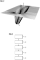
- Figure 2 shows schematically the three-dimensional shape of a cooling fluid opening determined in step b) of the method according to the invention.
- Figure 3 shows a scheme of a process according to the invention.
- the method according to the invention is, for example, particularly suitable for maintenance processes of components of a turbine, a compressor or a combustion chamber that have film cooling.
- the susceptibility to errors can be significantly reduced because, for example, the actual positions of the openings are determined and used for processing. Since it is typically assumed that there are limited repair options for corresponding components, the high-precision method according to the invention with optimized process and improved susceptibility to errors also increases the service life of the component.
- the position of the further cooling fluid openings typically is possible to predict the position of the further cooling fluid openings with sufficient accuracy based on interpolation processes and/or design data.
- the three-dimensional shape of at least 50%, more preferably at least 70%, even more preferably at least 80%, of the cooling fluid openings is determined.
- the three-dimensional shape of at least 95%, more preferably at least 99%, even more preferably of all cooling fluid openings is determined.
- the position of further cooling fluid openings can be determined using interpolation based on, for example, design data based on the position of a reference opening, it is typically preferred to determine the position of a larger number of cooling fluid openings. In further embodiments, it is therefore preferred that in step b) the position of at least 10%, more preferably at least 30%, even more preferably at least 60%, of the cooling fluid openings is determined. In particular, it is typically preferred that the position of at least 80%, more preferably at least 99%, even more preferably 100%, of the cooling fluid openings is determined. Determining the position of all cooling fluid openings is particularly advantageous when no design data is available or the reliability of the design data must be doubted.
- the two parts of the two-part surface analysis are carried out using different measuring devices.
- the measuring devices use different measuring methods.
- a measuring device based on laser triangulation methods or strip light projection can be used with a measuring device based on interferometry in order to obtain particularly high-quality measurement results particularly quickly.
- the method according to the invention comprises an evaluation of the data obtained in step b) between steps b) and d), wherein a damaged edge region of the at least one cooling fluid opening is corrected by means of fitting processes in order to obtain the original shape of the at least one cooling fluid opening.
- a damaged edge region of the at least one cooling fluid opening is corrected by means of fitting processes in order to obtain the original shape of the at least one cooling fluid opening.
- Cooling fluid channels can indeed also have complex shapes that cannot be interpolated with a certain distance from the cooling fluid opening. However, it has been shown that for the reopening of the cooling fluid openings according to the invention, the region of the cooling fluid channels directly adjoining the cooling fluid openings can be interpolated with sufficient accuracy, this region being sufficient to carry out highly precise reopening.
- the data obtained in step b) are compared with design data, such as CAD data of the component.
- design data such as CAD data of the component.
- the comparison of the data obtained with the design data includes a plausibility check, wherein the plausibility check includes in particular the number and position of the cooling fluid openings, as well as the shape and orientation of the cooling fluid channels, and wherein a defined action is triggered in the event of significant deviations. It is also possible to check for, for example, inadmissible deviations in the overall shape of the component.
- the term "significant deviation" in the sense of the present invention refers to significant deviations, wherein the person skilled in the art can define the limit of such a significant deviation based on his general specialist knowledge and/or customer specification. For example, he selects limits, if exceeded, the component would no longer meet the requirements.
- the specialist can, for example, set upper limits of deviations based on production fluctuations and/or corresponding error tolerances. This makes it possible, for example, to identify incorrectly assigned components and either automatically reject them or draw the attention of employees to them through appropriate feedback. Excessive damage to the cooling fluid openings can also be detected, for example, so that corresponding components can be rejected before the coating process and repaired if necessary.
- a corrected model of the component is generated based on the data obtained in step b), whereby existing design data is corrected.
- existing design data is corrected.
- existing systems that already work with the design data and corresponding models can be used.
- this allows the real shape of the corresponding component to be recorded. This allows, for example, the change in the components over time to be recorded.
- This data can in turn be used to optimize the components.
- this enables the clear identification of the components, which can be relevant, for example, in the event of later recourse claims.
- a simplified model of the component is generated based on the data obtained in step b).
- This simplified model includes the positions of the cooling fluid openings and information relating to the cooling fluid openings.
- the information relating to the cooling fluid openings can include, for example, the shape of the cooling fluid openings and the shape and orientation of the adjoining cooling fluid channels.
- the basis of this model can be, for example, the external shape of the component or the coordinate system of the device. This allows, in particular, processing without knowledge of the original design data. Furthermore, the calculation processes are significantly reduced, so that, for example, systems with lower computing power can be used for this. Although this means that less data can be obtained for long-term observation of the change in the component, this has typically proven to be sufficient if only the cooling fluid openings and cooling fluid channels of the component are in focus.
- the component is first rotated to quickly determine the position of the cooling fluid openings on the surface of the component before the three-dimensional shape of the at least one cooling fluid opening is specifically determined.
- the position of the cooling fluid openings is first determined before the shape of the at least one cooling fluid opening is determined. In particular, this simplifies the method in that the typically significantly different speeds of the two parts of the surface analysis do not interfere with each other.
- the general measurement of the surface and the precise measurement of the cooling fluid openings take place at least partially simultaneously.
- the component can be rotated inside the device while the inaccurate general measurement of the surface is carried out on one side, while the cooling fluid openings of the surface, which have already been found during the rotation, are precisely measured at a point that has already been measured. This can be advantageous, for example, if comparable components are to be processed one after the other.
- the resulting time saved during the surface analysis can compensate for the additional Balance the time and effort required for the specially adapted process control of the surface analysis.
- At least one cooling fluid opening is selected as a reference point.
- the location and determinability of the exact position of the cooling fluid opening and the adjoining channel are taken into account.
- deviations from the ideal geometry are also taken into account and, for example, damaged cooling fluid openings are less preferably selected as a reference point.
- a reference opening can also be used, for example, for quality control and comparison with the design data.
- the position of the cooling fluid openings and the three-dimensional shape of the at least one cooling fluid opening are determined using different measuring devices.
- different measuring devices instead of, for example, one measuring device that is operated with different resolutions typically produces more accurate results.
- Measuring methods such as rotary laser triangulation and interferometry-based measuring methods have proven to be advantageous for typical applications.
- rotary laser triangulation can be used to determine the position of the cooling fluid openings, while an interferometer is used to determine the shape of the at least one cooling fluid opening.
- the position of the cooling fluid openings and the three-dimensional shape of the at least one cooling fluid opening are determined with the same measuring device
- different measuring devices it may be possible to use different measuring devices to carry out the two parts of the surface scan, as this typically results in more precise data.
- a typically significantly different resolution of the measuring device is used for the two parts of the surface analysis. For example, this can be used to remember the space required by the device or, if the space required is the same, space can be made available within the device to integrate additional functions. Surprisingly, it has been found that this typically results in sufficient measurement data to be able to recreate the cooling fluid openings with sufficient accuracy.
- the data can be stored on a portable storage medium or on a storage unit integrated into a network.
- the portable storage unit can then be connected to the other device for opening the cooling fluid openings, for example, or the corresponding device can retrieve the data obtained from the storage unit integrated into the network via a network connection.
- subsequent processing steps are also to be carried out in the same device, it has typically proven advantageous to store the data externally. For example, this can ensure increased data security, and even if the device is damaged between the steps according to the invention and subsequent steps in particular, the data can be used for a replacement device.
- a damaged edge region of the at least one cooling fluid opening is corrected by means of fitting processes in order to to obtain the ideal shape of at least one cooling fluid opening, as well as the position and the ideal shape and orientation of the adjoining cooling fluid channel.
- the ideal shape and orientation here refers to the originally unintended shape and orientation of the corresponding component that was to be achieved as a result of the original design. Deviations from this typically result from production fluctuations, error tolerances or damage.
- the method according to the invention comprises, after step d), a step e), wherein e) after the coating in the area of the cooling fluid opening has been removed, the component is subjected to a surface analysis again in a device according to the invention, preferably the device.
- a device according to the invention preferably the device.
- quality control which is particularly interesting for highly stressed components such as those installed in the flow channel of a turbomachine.
- a model of the finished component or the repaired component can also be created and saved in order to answer subsequent questions, to prove to the customer that the desired specification has been met, or to correlate subsequent observations during operation with the actual shape of the component.
- the device and/or the method according to the invention can be used particularly advantageously in the manufacture or repair of components of a turbomachine.
- the component can be any component of a turbomachine provided with cooling fluid openings.
- corresponding turbomachines are steam turbines and gas turbines.
- the component is selected from the group consisting of blades and heat shields of a turbomachine.
- this is a guide vane or rotor blade.
- guide vanes and rotor blades can be found for example in the turbine unit of steam turbines and gas turbines or also in the compressor unit of gas turbines, which represent a turbo machine.
- Corresponding components are exposed to particularly high loads. Accordingly, regular maintenance, including the removal of an existing coating and application of a new coating, is required. Accordingly, corresponding components and corresponding processes related to these components particularly benefit from the method according to the invention and use of the device according to the invention.
- such components are made at least partially from high-temperature resistant alloys such as iron, nickel or cobalt-based superalloys.
- high-temperature resistant alloys such as iron, nickel or cobalt-based superalloys.
- superalloys are, for example, from the EP 1 204 776 B1 , EP1 306 454 , EP 1 319 729 A1 , WO 99/67435 or WO 00/44949
- nickel superalloys are often used because they are advantageous for many applications.
- the corresponding components are single-crystal (SX structure).
- Such monocrystalline workpieces is carried out, for example, by directional solidification from the melt. This involves casting processes in which the liquid metallic alloy solidifies into a monocrystalline structure, i.e. into a monocrystalline workpiece, or solidifies in a direction.
- dendritic crystals are aligned along the heat flow and form either a columnar grain structure (i.e. grains that run the entire length of the workpiece and are referred to here, in common parlance, as directionally solidified) or a monocrystalline structure, i.e. the entire workpiece consists of a single crystal.
- a columnar grain structure i.e. grains that run the entire length of the workpiece and are referred to here, in common parlance, as directionally solidified
- a monocrystalline structure i.e. the entire workpiece consists of a single crystal.
- directionally solidified structures we mean both single crystals that have no grain boundaries or at most small-angle grain boundaries, and columnar crystal structures that have grain boundaries running in a longitudinal direction but no transverse grain boundaries. These latter crystalline structures are also referred to as directionally solidified structures.
- the components can also have coatings against corrosion or oxidation, e.g. (MCrAlX; M is at least one element from the group iron (Fe), cobalt (Co), nickel (Ni), X is an active element and stands for yttrium (Y) and/or silicon and/or at least one element from the rare earths, or hafnium (Hf)).
- M is at least one element from the group iron (Fe), cobalt (Co), nickel (Ni)
- X is an active element and stands for yttrium (Y) and/or silicon and/or at least one element from the rare earths, or hafnium (Hf)).
- Such alloys are known from the EP0486489B1 , EP0786017B1 , EP0412397B1 or EP1306454A1 .
- the density is preferably 95% of the theoretical density.
- the layer composition comprises Co-30Ni-28Cr-8Al-0.6Y-0.7Si or Co-28Ni-24Cr-10Al-0.6Y.
- nickel-based protective layers are also preferably used, such as Ni-10Cr-12Al-0.6Y-3Re or Ni-12Co-21Cr-11Al-0.4Y-2Re or Ni-25Co-17Cr-10Al-0.4Y-1.5Re.
- a thermal insulation layer may also be present on the MCrAlX, which is preferably the outermost layer, and consists for example of ZrO 2 , Y 2 O 3 -ZrO 2 , ie it is not, partially or completely stabilized by yttrium oxide and/or calcium oxide and/or magnesium oxide.
- the thermal insulation layer covers the entire MCrAlX layer.
- EB-PVD electron beam evaporation
- the thermal insulation layer can have porous grains with micro or macro cracks for better thermal shock resistance.
- the thermal insulation layer is therefore preferably more porous than the MCrAlX layer.
- Refurbishment means that components may need to be freed of protective layers after use (e.g. by sandblasting). The corrosion and/or oxidation layers or products are then removed. If necessary, cracks or other damage to the component are also repaired. The component is then recoated to enable it to be used again.
- the devices according to the invention are particularly suitable for the surface analysis of components which are used in turbomachines and are exposed to the flow of the fluid used therein. Surprisingly, it was found that the devices according to the invention, which, among other things, have the option of two-part surface analysis, can provide the data required for such cases with minimal effort and maximum speed.
- the device has at least two Measuring devices. Although this increases the effort required to provide the device, it was surprisingly found that this additional effort is more than compensated for by, for example, the increased speed of synchronous measurements on different sides of the component. For example, it was surprisingly found that the time saved is particularly relevant for the method according to the invention, since this can compensate for the time lost through the two-part surface analysis and the overall efficiency of the method is significantly increased. The use of different measuring devices has also proven to be surprisingly advantageous for the method according to the invention.
- the device has a movable measuring device, wherein the movable measuring device has a robot arm.
- the movable measuring device has a robot arm.
- a high-precision analysis unit can also be angled particularly easily or brought closer to the component that is to be measured.
- the measuring device for determining the three-dimensional shape of the at least one cooling fluid opening is movable.
- the device has a movable measuring device and the movable measuring device can be tilted by at least 10°, more preferably at least 20°, even more preferably at least 25°. It was found that the ability to tilt the analysis unit by such small angles already enabled a significantly more flexible and precise analysis. In particular, in view of the alignment of the cooling fluid channels which adjoin the cooling fluid opening, for example, a better alignment of the analysis unit can be achieved, so that the measurement results have a significantly higher degree of accuracy.
- the measuring device can be tilted at least partially in the direction of the cooling fluid channel in order to also cover a larger part of the initial area of the cooling fluid channel.
- the device provides different measuring devices for the two parts of the surface analysis.
- the provision of different measuring devices, which are adapted to the respective measurement, in particular by using different measuring methods, has proven to be advantageous in particular for the provision of higher quality data.
- the device provides at least one measuring device that can be operated in different modes and is suitable for carrying out both parts of the surface scan one after the other. This allows, for example, the provision of particularly simply constructed and cost-effective devices according to the invention.
- the position of the cooling fluid openings and the three-dimensional shape of the at least one cooling fluid opening are determined using the same measuring device. It may be advantageous for many applications to use different measuring devices to carry out the two measurements, since this typically yields more precise data. However, to provide a particularly simply constructed device, it may be preferable to use the same measuring method for both measurements. For example, this can be used to remember the space required by the device or, if the space required is the same, to provide space within the device to integrate additional functions. Surprisingly, it has been found that this typically yields sufficient measurement data to be able to recreate the cooling fluid openings with sufficient accuracy.
- the at least one fastening of the device is movable and the movable fastening is suitable for providing a rotation of the component by at least 270°.
- This device has typically proven to be particularly advantageous, since a complete measurement of the component can be carried out even with a small amount of movement of the sensor unit. For example, even if a rotation of at least 360° is provided, it is theoretically possible to dispense with the mobility of the analysis unit to determine the positions of the cooling fluid openings in at least 2 axes or even completely. For example, in these cases it may be sufficient to allow the analysis unit to move along a rail on which the analysis unit is moved up and down while the component is rotated in front of it. This has proven to be particularly advantageous, particularly for sensitive analysis units where unnecessary movements should be avoided.
- step b) of the inventive method uses the data obtained in step b) of the inventive method to generate a corrected model based on existing design data.
- This makes it possible, for example, to obtain a model of the actual component, with production fluctuations and deviations due to error tolerances being corrected by the measurement.
- This is advantageous, for example, for simulations in which, for example, the service life of the component is simulated under different conditions based on the model.
- this is advantageous, for example, for incoming inspection of prefabricated components or for optimized automated processing and/or maintenance of corresponding components. Due to production errors and/or error tolerances, real components typically deviate at least minimally from the theoretical design data. Due to the increased requirements in recent years, minor Deviations, particularly for subsequent maintenance work or optimized simulation processes in which, for example, the service life of a component is predicted with high precision, have grown steadily. Since the method according to the invention and/or use of the device according to the invention can be used to obtain highly relevant information on the actual condition of the component using simple means, from which further features can also be derived, this has proven to be particularly advantageous.
- the corrected model is suitable for enabling automated opening of the cooling fluid openings after coating the component.
- a device according to the invention can be used for this purpose.
- Figure 1 shows schematically the outside of a turbine blade 1 as an example of the component comprising a plurality of cooling fluid openings 2, which are connected to the cooling channels of the turbine blade 1.
- the existing coating of the turbine blade 1 is removed, damage is repaired and the turbine blade 1 is coated again.
- the removal of an existing coating is naturally omitted, unless the component has to be re-processed due to faulty processing.
- the coating is typically applied to the area above the platform 3, since this area is exposed to the fluid flow during operation of a gas turbine, for example.
- the part below the platform 3 is not exposed to the fluid flow and can therefore be used without the additional protective coating.
- the shape of the lower part allows the component to be reliably fixed, for example, to the rotor of a gas turbine. Due to the insufficient footprint, the component must be fixed during the processing steps. This can be done, for example, by a mobile holder which mechanically grips the area of the turbine blade 1 below the platform 3 and is itself attached to a fastening in the device according to the invention.
- FIG. 2 shows a high-resolution scan of a cooling fluid opening 2, which is connected to a cooling fluid channel of the Figure 1 shown turbine blade 1.
- the three-dimensional shape of the cooling fluid opening 2, which is followed by the initial region 4 of the cooling fluid channel, is clearly visible, and the cooling fluid channel that follows this can also be interpolated with sufficient accuracy.
- the observable surface irregularities resulting from measurement inaccuracies and/or damage to the surface of a cooling fluid opening 2 can be removed, for example, by means of a fitting process.
- Figure 3 shows a flow chart of the process according to the invention.
- the component such as the one in Figure 1 shown turbine blade 1, according to step a) of the method according to the invention, is introduced into a device according to the invention.
- the device comprises at least two measuring devices and at least one fastening.
- a bracket can be attached to the fastening, which in turn supports the lower part of the Figure 1 shown turbine blade 1.
- the turbine blade 1 is thereby indirectly and releasably fixed in the device during the method according to the invention.
- step S2 data are provided regarding the position of the cooling fluid openings 2 on the surface of the component as well as the three-dimensional shape of at least one cooling fluid opening.
- the data is determined using various measuring devices.
- the use of different measuring devices allows, for example, the parallel determination of the data regarding the position of the cooling fluid openings, as well as the three-dimensional shape of the at least one cooling fluid opening.
- One of the two measuring devices is suitable for carrying out a large-area surface analysis, whereby the positions of the cooling fluid openings 2 are determined.
- a measuring device that works by means of rotational laser triangulation can be used.
- the other of the two measuring devices is suitable for detecting the three-dimensional shape of the cooling fluid openings 2.
- a measuring device based on interferometry can be used for this purpose.
- the measuring device for determining the three-dimensional shape of the at least one cooling fluid opening 2 can, for example, be attached to a robot arm, which provides a high degree of mobility of the measuring device.
- the corresponding measuring device can, for example, be at least partially moved in the direction of of the respective adjoining cooling fluid channel in order to obtain more relevant data.
- a device not according to the invention can be used which uses the same measuring device for both parts of the surface analysis. For example, a quick measurement with low resolution is first carried out to determine the positions of the cooling fluid openings 2, before the three-dimensional shape of the at least one cooling fluid opening 2 is determined with high resolution. This enables a significantly simpler structure of the device, but typically less detailed information is obtained.
- the two parts of the surface scan Since the time required for the two parts of the surface scan is typically different, it may be preferable for the two parts to be carried out separately in order to provide a generally applicable process. For example, a rapid rotation of the component is first carried out to determine the position of the cooling fluid openings 2. Subsequently, the exact three-dimensional shape of the at least one cooling fluid opening 2 is determined during a further rotation of the component.
- the measuring device for precise measurement of the cooling fluid openings 2 is attached to a robot arm. This allows optimal positioning of this measuring device in order to obtain particularly high-quality measurement data of the cooling fluid openings 2. Furthermore, a further improvement can be achieved by a synchronous movement corresponding to the rotation of the component, particularly in a synchronized measuring process of different measuring devices.
- the measuring device offers the possibility of being tilted by at least 10° for the precise measurement of the at least one cooling fluid opening 2. This allows the alignment of the measuring device to be adjusted, for example to allow a larger part of the cooling fluid channel adjoining the cooling fluid opening 2.
- the turbine blade 1 can be removed from the device according to the invention, for example to carry out optional processing steps and/or to apply the coating. If the device according to the invention is suitable for this, such steps can naturally also be carried out in it.
- a coating is applied to the component, whereby the cooling fluid opening 2 is at least partially closed.
- a ceramic coating is preferably applied, which typically particularly advantageously increases the temperature resistance. This can be applied using known methods.
- step S4 the coating in the area of the cooling fluid opening is removed.
- the coating can be removed, for example, using a drilling laser or other suitable drill.
- the data obtained in step S2 is used to precisely remove the coating so that the planned cooling is restored.
- step S5 after the removal of the coating in the area of the at least one cooling fluid opening 2 in step S4, a measurement can be carried out again using the device measured according to the invention in a similar way to S2.
- a measurement can be carried out again using the device measured according to the invention in a similar way to S2.
- the component can subsequently be subjected again to the method according to the invention
- the method can be started again from S1.
- a quality control can also be carried out using a transmission test in order to test the undisturbed flow of the cooling medium through the cooling fluid channels.
- the data received can be compared with the design data, such as CAD data of the component, in step S5. Relevant changes can also be detected automatically and, for example, sent to an expert for review.
- a corrected model of the component can be generated in step S5.
- a corrected model of the real component is generated based on existing design data and compared with the measured data of the at least one cooling fluid opening 2 and the cooling fluid channels connected to it.
- This model can also be simplified in such a way that, for example, only absolutely necessary data, such as the external shape or prominent points of the external shape, as well as the relative position of the at least one cooling fluid opening 2 and the associated information, are recorded.
Landscapes
- Engineering & Computer Science (AREA)
- Mechanical Engineering (AREA)
- General Engineering & Computer Science (AREA)
- Physics & Mathematics (AREA)
- General Physics & Mathematics (AREA)
- Chemical & Material Sciences (AREA)
- Combustion & Propulsion (AREA)
- Fluid Mechanics (AREA)
- Materials Engineering (AREA)
- Computer Vision & Pattern Recognition (AREA)
- Turbine Rotor Nozzle Sealing (AREA)
Claims (13)
- Procédé de revêtement d'une pièce comprenant une surface comprenant des ouvertures de fluide de refroidissement qui se raccordent à des conduits de fluide de refroidissement à l'intérieur de la pièce, dans lequel le procédé comprend les stades suivants :a) insertion de la pièce dans une installation d'analyse de surface de la pièce,dans lequel l'installation comprend au moins deux installations de mesure et au moins une fixation de la pièce,dans lequel la fixation est propre à être reliée à la pièce, de manière détachable directement ou indirectement,dans lequel l'installation est propre à effectuer une analyse de surface en deux parties, dans lequel dans une première partie de l'analyse de surface, on détermine la position des ouvertures (2) de fluide de refroidissement à la surface de la pièce, et dans lequel dans une autre partie de l'analyse de surface, on détecte la forme en trois dimensions d'au moins une ouverture (2) de fluide de refroidissement,dans lequel au moins un élément choisi dans le groupe constitué des au moins deux dispositifs de mesure différents et de la au moins une fixation est mobile,b) on effectue l'analyse de surface de la pièce, dans lequel on détecte des données concernant la position des ouvertures (2) de fluide de refroidissement à la surface de la pièce et concernant la forme en trois dimensions d'au moins une ouverture (2) de fluide de refroidissement,c) on dépose un revêtement sur la pièce, dans lequel on ferme les ouvertures (2) de fluide de refroidissement au moins en partie, de préférence complètement,d) on élimine le revêtement dans la partie des ouvertures de fluide de refroidissement, au moyen des données obtenues au stade b),dans lequel on effectue les deux parties de l'analyse de surface en deux parties par les installations de mesure différentes.
- Procédé suivant la revendication 1, dans lequel les installations de mesure différentes utilisent les procédés de mesure différents.
- Procédé suivant l'une des revendications 1 à 2, dans lequel la détermination de la position des ouvertures (2) de fluide de refroidissement à la surface de la pièce s'effectue au moyen d'une triangulation laser à rotation et/ou on détecte la forme en trois dimensions d'au moins une ouverture (2) de fluide de refroidissement au moyen d'un interféromètre.
- Procédé suivant l'une des revendications 1 à 3, dans lequel on détermine la forme en trois dimensions d'au moins 50% des ouvertures (2) de fluide de refroidissement.
- Procédé suivant l'une des revendications 1 à 4, dans lequel on choisit la pièce dans le groupe constitué d'aubes (1) et de boucliers thermiques d'une turbomachine.
- Procédé suivant l'une des revendications 1 à 5, comprenant entre le stade b) et d) une évaluation des données de l'analyse de surface de la pièce obtenues au stade b) afin d'établir un ensemble de données comprenant de l'information concernant la position, la forme et la direction des conduits de fluide de refroidissement se raccordant aux ouvertures (2) de fluide de refroidissement.
- Procédé suivant l'une des revendications 1 à 6, comprenant entre le stade b) et d) une évaluation des données obtenues au stade b), dans lequel on corrige une partie de bord endommagée de la au moins une ouverture (2) de fluide de refroidissement, au moyen de processus d'ajustement pour obtenir la forme d'origine de la au moins une ouverture (2) de fluide de refroidissement.
- Procédé suivant l'une des revendications 1 à 7, dans lequel on ajuste les données obtenues au stade b) par des données de construction de la pièce.
- Procédé suivant l'une des revendications 1 à 8, dans lequel on produit un modèle corrigé de la pièce sur la base des données obtenues au stade b), des données de construction existantes étant corrigées.
- Installation d'analyse de surface d'une pièce comprenant une surface comprenant des ouvertures (2) de fluide de refroidissement qui se raccordent à des conduits de fluide de refroidissement à l'intérieur de la pièce,dans laquelle l'installation comprend au moins deux installations de mesure et au moins une fixation de la pièce, dans laquelle la fixation est propre à être reliée à la pièce de manière détachable directement ou indirectement, dans laquelle l'installation comprend des moyens pour effectuer une analyse de surface en deux parties,dans laquelle dans une partie de l'analyse de surface, on détermine la position des ouvertures (2) de fluide de refroidissement à la surface de la pièce, et dans laquelle dans une autre partie de l'analyse de surface, on détecte la forme en trois dimensions d'au moins une ouverture (2) de fluide de refroidissement,dans laquelle au moins un élément choisi dans le groupe constitué des au moins deux dispositifs de mesure différents et de la au moins une fixation est mobile, dans laquelle l'installation dispose d'installations de mesure différentes pour les deux parties de l'analyse de surface, dans laquelle on utilise les moyens pour effectuer l'analyse de surface en deux parties et les installations de mesure différentes selon un procédé suivant l'une des revendications 1 à 9, pour effectuer les deux parties de l'analyse de surface en deux parties par des installations de mesure différentes.
- Installation suivant la revendication 10, dans laquelle l'installation a une installation de mesure mobile et
dans laquelle l'installation de mesure mobile a un bras de robot. - Installation suivant l'une des revendications 10 à 11, dans laquelle la au moins une fixation est mobile et dans laquelle la fixation mobile est propre à donner une rotation de la pièce d'au moins 270°.
- Utilisation d'une installation suivant l'une des revendications 10 à 12 et/ou d'un procédé suivant l'une des revendications 1 à 9 pour la production ou la réparation de pièces d'une turbomachine.
Applications Claiming Priority (2)
| Application Number | Priority Date | Filing Date | Title |
|---|---|---|---|
| DE102018211288.6A DE102018211288A1 (de) | 2018-07-09 | 2018-07-09 | Vorrichtung und Verfahren zur Oberflächenanalyse von Bauteilen mit Kühlfluidöffnungen |
| PCT/EP2019/068127 WO2020011673A1 (fr) | 2018-07-09 | 2019-07-05 | Dispositif et procédé pour analyser la surface de composants présentant des ouvertures pour fluide de refroidissement |
Publications (2)
| Publication Number | Publication Date |
|---|---|
| EP3775765A1 EP3775765A1 (fr) | 2021-02-17 |
| EP3775765B1 true EP3775765B1 (fr) | 2024-09-04 |
Family
ID=67297151
Family Applications (1)
| Application Number | Title | Priority Date | Filing Date |
|---|---|---|---|
| EP19739954.6A Active EP3775765B1 (fr) | 2018-07-09 | 2019-07-05 | Dispositif et procédé pour analyser la surface de composants présentant des ouvertures pour fluide de refroidissement |
Country Status (4)
| Country | Link |
|---|---|
| US (1) | US11529704B2 (fr) |
| EP (1) | EP3775765B1 (fr) |
| DE (1) | DE102018211288A1 (fr) |
| WO (1) | WO2020011673A1 (fr) |
Families Citing this family (2)
| Publication number | Priority date | Publication date | Assignee | Title |
|---|---|---|---|---|
| US11840032B2 (en) * | 2020-07-06 | 2023-12-12 | Pratt & Whitney Canada Corp. | Method of repairing a combustor liner of a gas turbine engine |
| DE102021208965A1 (de) | 2021-08-16 | 2023-02-16 | HPL Technologies GmbH | Werkstück zum Beschichten mit einer Veredelungsschicht, sowie ein Einmessverfahren für ein Werkstück |
Family Cites Families (38)
| Publication number | Priority date | Publication date | Assignee | Title |
|---|---|---|---|---|
| US4176433A (en) * | 1978-06-29 | 1979-12-04 | United Technologies Corporation | Method of remanufacturing turbine vane clusters for gas turbine engines |
| US4334495A (en) * | 1978-07-11 | 1982-06-15 | Trw Inc. | Method and apparatus for use in making an object |
| DE3926479A1 (de) | 1989-08-10 | 1991-02-14 | Siemens Ag | Rheniumhaltige schutzbeschichtung, mit grosser korrosions- und/oder oxidationsbestaendigkeit |
| DE58908611D1 (de) | 1989-08-10 | 1994-12-08 | Siemens Ag | Hochtemperaturfeste korrosionsschutzbeschichtung, insbesondere für gasturbinenbauteile. |
| US5216808A (en) * | 1990-11-13 | 1993-06-08 | General Electric Company | Method for making or repairing a gas turbine engine component |
| DE59505454D1 (de) | 1994-10-14 | 1999-04-29 | Siemens Ag | Schutzschicht zum schutz eines bauteils gegen korrosion, oxidation und thermische überbeanspruchung sowie verfahren zu ihrer herstellung |
| US5773790A (en) * | 1997-01-21 | 1998-06-30 | General Electric Company | Beam blocking material and method for beam drilling and inspecting cooling holes |
| EP0861927A1 (fr) | 1997-02-24 | 1998-09-02 | Sulzer Innotec Ag | Procédé de fabrication de structures monocristallines |
| EP0892090B1 (fr) | 1997-02-24 | 2008-04-23 | Sulzer Innotec Ag | Procédé de fabrication de structure monocristallines |
| EP1306454B1 (fr) | 2001-10-24 | 2004-10-06 | Siemens Aktiengesellschaft | Revêtement protecteur contenant du rhénium pour la protection d'un élément contre l'oxydation et la corrosion aux températures élevées |
| WO1999067435A1 (fr) | 1998-06-23 | 1999-12-29 | Siemens Aktiengesellschaft | Alliage a solidification directionnelle a resistance transversale a la rupture amelioree |
| US6231692B1 (en) | 1999-01-28 | 2001-05-15 | Howmet Research Corporation | Nickel base superalloy with improved machinability and method of making thereof |
| JP2003529677A (ja) | 1999-07-29 | 2003-10-07 | シーメンス アクチエンゲゼルシヤフト | 耐熱性の構造部材及びその製造方法 |
| US6909800B2 (en) * | 2000-12-15 | 2005-06-21 | United Technologies Corporation | Process and apparatus for locating coated cooling holes on turbine vanes |
| US6524395B1 (en) * | 2001-09-21 | 2003-02-25 | General Electric Company | Method and apparatus for locating and repairing cooling orifices of airfoils |
| US6380512B1 (en) * | 2001-10-09 | 2002-04-30 | Chromalloy Gas Turbine Corporation | Method for removing coating material from a cooling hole of a gas turbine engine component |
| DE50112339D1 (de) | 2001-12-13 | 2007-05-24 | Siemens Ag | Hochtemperaturbeständiges Bauteil aus einkristalliner oder polykristalliner Nickel-Basis-Superlegierung |
| US6723951B1 (en) * | 2003-06-04 | 2004-04-20 | Siemens Westinghouse Power Corporation | Method for reestablishing holes in a component |
| DE10335657B4 (de) * | 2003-08-04 | 2015-04-30 | Alstom Technology Ltd. | Parametrische Herstellung von Kühlbohrungen |
| ATE375841T1 (de) * | 2003-08-27 | 2007-11-15 | Alstom Technology Ltd | Adaptive automatisierte bearbeitung von überfüllten kanälen |
| US20060291716A1 (en) * | 2005-06-28 | 2006-12-28 | Janakiraman Vaidyanathan | Thermal imaging and laser scanning systems and methods for determining the location and angular orientation of a hole with an obstructed opening residing on a surface of an article |
| US7333218B2 (en) * | 2005-06-28 | 2008-02-19 | United Technologies Corporation | Systems and methods for determining the location and angular orientation of a hole with an obstructed opening residing on a surface of an article |
| US20090297336A1 (en) * | 2007-08-21 | 2009-12-03 | General Electric Company | Online systems and methods for thermal inspection of parts |
| US7578178B2 (en) * | 2007-09-28 | 2009-08-25 | United Technologies Corporation | Method of inspecting turbine internal cooling features using non-contact scanners |
| US8328517B2 (en) * | 2008-09-16 | 2012-12-11 | Siemens Energy, Inc. | Turbine airfoil cooling system with diffusion film cooling hole |
| EP2312122A1 (fr) * | 2009-10-15 | 2011-04-20 | Siemens Aktiengesellschaft | Détermination d'une référence pour l'établissement de la position de trous bouchés, dispositif et dispositif d'usinage |
| EP2314987A1 (fr) * | 2009-10-20 | 2011-04-27 | Siemens Aktiengesellschaft | Analyse de surfaces pour la détection de trous fermés et dispositif |
| US9476842B2 (en) * | 2010-05-03 | 2016-10-25 | United Technologies Corporation | On-the-fly dimensional imaging inspection |
| US9976851B2 (en) * | 2010-05-03 | 2018-05-22 | United Technologies Corporation | Accurate machine tool inspection of turbine airfoil |
| EP2428765A1 (fr) | 2010-09-14 | 2012-03-14 | Siemens Aktiengesellschaft | Procédé et dispositif de traitement d'aubes de turbines |
| EP2428795A1 (fr) * | 2010-09-14 | 2012-03-14 | Siemens Aktiengesellschaft | Appareil et procédé d'inspection automatique d'orifices de passage d'un composant |
| GB201017506D0 (en) * | 2010-10-15 | 2010-12-01 | Rolls Royce Plc | Hole inspection |
| US10815796B2 (en) * | 2013-01-30 | 2020-10-27 | Raytheon Technologies Corporation | Coating process for gas turbine engine component with cooling holes |
| EP2845918A1 (fr) * | 2013-09-04 | 2015-03-11 | Siemens Aktiengesellschaft | Procédé destiné à revêtir au moins partiellement une aube, dispositif de revêtement et aube |
| US20150160644A1 (en) | 2013-12-05 | 2015-06-11 | General Electric Company | Repair method, system for automatic locating and clearing and tool for automated locating and modifying |
| US9707645B2 (en) * | 2014-01-09 | 2017-07-18 | General Electric Company | Systems, methods, and apparatus for locating and drilling closed holes of a turbine component |
| US20160186626A1 (en) * | 2014-12-30 | 2016-06-30 | General Electric Company | Engine component and methods for an engine component |
| US9752440B2 (en) * | 2015-05-29 | 2017-09-05 | General Electric Company | Turbine component having surface cooling channels and method of forming same |
-
2018
- 2018-07-09 DE DE102018211288.6A patent/DE102018211288A1/de not_active Withdrawn
-
2019
- 2019-07-05 EP EP19739954.6A patent/EP3775765B1/fr active Active
- 2019-07-05 US US17/251,783 patent/US11529704B2/en active Active
- 2019-07-05 WO PCT/EP2019/068127 patent/WO2020011673A1/fr not_active Ceased
Also Published As
| Publication number | Publication date |
|---|---|
| WO2020011673A1 (fr) | 2020-01-16 |
| EP3775765A1 (fr) | 2021-02-17 |
| DE102018211288A1 (de) | 2020-01-09 |
| US11529704B2 (en) | 2022-12-20 |
| US20210207484A1 (en) | 2021-07-08 |
Similar Documents
| Publication | Publication Date | Title |
|---|---|---|
| EP1844893B1 (fr) | Méthode d'enlèvement de matériau de revêtement des trous de refroidissement d'une pièce de turbine | |
| EP2602433B1 (fr) | Méthode de fabrication d'un composant de turbine à gaz revêtu et ayant des ouvertures | |
| EP2876183B1 (fr) | Procédé et dispositif d'application automatique d'un revêtement par pulvérisation | |
| EP2753895A1 (fr) | Système d'inspection de surface 3d au moyen de prises de vue 2d et procédé | |
| EP2591872A1 (fr) | Procédé de refonte et de remplissage ultérieur et composant obtenu | |
| EP2491339A1 (fr) | Analyse de surface pour détecter des trous obturés et dispositif | |
| EP2770296A1 (fr) | Procédé de marquage d'objet au moyen d'un système d'inspection de surface en 3D doté d'enregistrements en 2D et procédé | |
| EP3775765B1 (fr) | Dispositif et procédé pour analyser la surface de composants présentant des ouvertures pour fluide de refroidissement | |
| EP3512661B1 (fr) | Procédé de determination de la position d'une plateforme pour la fabrication additive avec identification de la plateforme par des points de référence | |
| WO2011047890A1 (fr) | Procédé pour mesurer une épaisseur de couche au moyen d'une triangulation laser et dispositif | |
| EP2682832A1 (fr) | Dispositif de serrage pour le serrage des aubes de turbines et procédé de fabrication du dispositif | |
| EP2878697A1 (fr) | Procédé de fabrication d'une fibre, élément doté de fibre et dispositif | |
| EP2613133B1 (fr) | Fabrication de corps de test comparatif pour le contrôle non destructif avec des fissures représentatives relatives à leur orientation et procédé d'examen | |
| EP2900921B1 (fr) | Méthode de traitement d'une pièce avec adaptation à sa géométrie | |
| EP2308628A1 (fr) | Méthode d'enlévement d'un composant brasé avec chauffage local du lieu de brasage | |
| EP2774710A1 (fr) | Surfaces et réparation de fissures par différents matériaux de brasage | |
| WO2011045343A1 (fr) | Détermination de référence pour la détermination de la position de trous fermés, dispositif et dispositif d'usinage | |
| EP2100689A1 (fr) | Dispositif et procédé de commande de faisceaux | |
| EP2591877A1 (fr) | Procédé de refonte sous atmosphère de gaz réactif | |
| EP2743635A1 (fr) | Reconnaissance de position de composants | |
| DE102018211284A1 (de) | Vorrichtung und Verfahren zum Entfernen von Beschichtungsmaterial aus Kühlfluidöffnungen eines Bauteils | |
| EP1978790B1 (fr) | Dispositif et procédé destinés au revêtement d'un composant doté d'un dispositif d'ajustement | |
| EP3074175B1 (fr) | Machine-outil | |
| DE102013225917A1 (de) | Verfahren und Vorrichtung zum Wiederöffnen von Löchern in einem Bauteil nach einem Beschichtungsprozess | |
| EP3588218A1 (fr) | Procédé d'usinage d'une pièce à usiner destinée à la fabrication d'une partie de gaz chaud |
Legal Events
| Date | Code | Title | Description |
|---|---|---|---|
| STAA | Information on the status of an ep patent application or granted ep patent |
Free format text: STATUS: UNKNOWN |
|
| STAA | Information on the status of an ep patent application or granted ep patent |
Free format text: STATUS: THE INTERNATIONAL PUBLICATION HAS BEEN MADE |
|
| PUAI | Public reference made under article 153(3) epc to a published international application that has entered the european phase |
Free format text: ORIGINAL CODE: 0009012 |
|
| STAA | Information on the status of an ep patent application or granted ep patent |
Free format text: STATUS: REQUEST FOR EXAMINATION WAS MADE |
|
| 17P | Request for examination filed |
Effective date: 20201109 |
|
| AK | Designated contracting states |
Kind code of ref document: A1 Designated state(s): AL AT BE BG CH CY CZ DE DK EE ES FI FR GB GR HR HU IE IS IT LI LT LU LV MC MK MT NL NO PL PT RO RS SE SI SK SM TR |
|
| AX | Request for extension of the european patent |
Extension state: BA ME |
|
| DAV | Request for validation of the european patent (deleted) | ||
| DAX | Request for extension of the european patent (deleted) | ||
| STAA | Information on the status of an ep patent application or granted ep patent |
Free format text: STATUS: EXAMINATION IS IN PROGRESS |
|
| 17Q | First examination report despatched |
Effective date: 20230223 |
|
| GRAP | Despatch of communication of intention to grant a patent |
Free format text: ORIGINAL CODE: EPIDOSNIGR1 |
|
| STAA | Information on the status of an ep patent application or granted ep patent |
Free format text: STATUS: GRANT OF PATENT IS INTENDED |
|
| RIC1 | Information provided on ipc code assigned before grant |
Ipc: F23R 3/06 20060101ALI20240226BHEP Ipc: F02K 1/82 20060101ALI20240226BHEP Ipc: F01D 9/06 20060101ALI20240226BHEP Ipc: F01D 9/02 20060101ALI20240226BHEP Ipc: F01D 5/28 20060101ALI20240226BHEP Ipc: F01D 5/18 20060101ALI20240226BHEP Ipc: B23P 6/00 20060101ALI20240226BHEP Ipc: G01B 11/245 20060101ALI20240226BHEP Ipc: G01B 11/25 20060101ALI20240226BHEP Ipc: F01D 5/00 20060101ALI20240226BHEP Ipc: G01B 11/24 20060101AFI20240226BHEP |
|
| INTG | Intention to grant announced |
Effective date: 20240314 |
|
| GRAS | Grant fee paid |
Free format text: ORIGINAL CODE: EPIDOSNIGR3 |
|
| GRAA | (expected) grant |
Free format text: ORIGINAL CODE: 0009210 |
|
| STAA | Information on the status of an ep patent application or granted ep patent |
Free format text: STATUS: THE PATENT HAS BEEN GRANTED |
|
| AK | Designated contracting states |
Kind code of ref document: B1 Designated state(s): AL AT BE BG CH CY CZ DE DK EE ES FI FR GB GR HR HU IE IS IT LI LT LU LV MC MK MT NL NO PL PT RO RS SE SI SK SM TR |
|
| REG | Reference to a national code |
Ref country code: GB Ref legal event code: FG4D Free format text: NOT ENGLISH |
|
| REG | Reference to a national code |
Ref country code: CH Ref legal event code: EP |
|
| REG | Reference to a national code |
Ref country code: IE Ref legal event code: FG4D Free format text: LANGUAGE OF EP DOCUMENT: GERMAN |
|
| REG | Reference to a national code |
Ref country code: DE Ref legal event code: R096 Ref document number: 502019012053 Country of ref document: DE |
|
| REG | Reference to a national code |
Ref country code: LT Ref legal event code: MG9D |
|
| REG | Reference to a national code |
Ref country code: NL Ref legal event code: MP Effective date: 20240904 |
|
| PG25 | Lapsed in a contracting state [announced via postgrant information from national office to epo] |
Ref country code: NO Free format text: LAPSE BECAUSE OF FAILURE TO SUBMIT A TRANSLATION OF THE DESCRIPTION OR TO PAY THE FEE WITHIN THE PRESCRIBED TIME-LIMIT Effective date: 20241204 |
|
| PG25 | Lapsed in a contracting state [announced via postgrant information from national office to epo] |
Ref country code: GR Free format text: LAPSE BECAUSE OF FAILURE TO SUBMIT A TRANSLATION OF THE DESCRIPTION OR TO PAY THE FEE WITHIN THE PRESCRIBED TIME-LIMIT Effective date: 20241205 Ref country code: PL Free format text: LAPSE BECAUSE OF FAILURE TO SUBMIT A TRANSLATION OF THE DESCRIPTION OR TO PAY THE FEE WITHIN THE PRESCRIBED TIME-LIMIT Effective date: 20240904 Ref country code: FI Free format text: LAPSE BECAUSE OF FAILURE TO SUBMIT A TRANSLATION OF THE DESCRIPTION OR TO PAY THE FEE WITHIN THE PRESCRIBED TIME-LIMIT Effective date: 20240904 |
|
| PG25 | Lapsed in a contracting state [announced via postgrant information from national office to epo] |
Ref country code: BG Free format text: LAPSE BECAUSE OF FAILURE TO SUBMIT A TRANSLATION OF THE DESCRIPTION OR TO PAY THE FEE WITHIN THE PRESCRIBED TIME-LIMIT Effective date: 20240904 |
|
| PG25 | Lapsed in a contracting state [announced via postgrant information from national office to epo] |
Ref country code: LV Free format text: LAPSE BECAUSE OF FAILURE TO SUBMIT A TRANSLATION OF THE DESCRIPTION OR TO PAY THE FEE WITHIN THE PRESCRIBED TIME-LIMIT Effective date: 20240904 |
|
| PG25 | Lapsed in a contracting state [announced via postgrant information from national office to epo] |
Ref country code: HR Free format text: LAPSE BECAUSE OF FAILURE TO SUBMIT A TRANSLATION OF THE DESCRIPTION OR TO PAY THE FEE WITHIN THE PRESCRIBED TIME-LIMIT Effective date: 20240904 |
|
| PG25 | Lapsed in a contracting state [announced via postgrant information from national office to epo] |
Ref country code: ES Free format text: LAPSE BECAUSE OF FAILURE TO SUBMIT A TRANSLATION OF THE DESCRIPTION OR TO PAY THE FEE WITHIN THE PRESCRIBED TIME-LIMIT Effective date: 20240904 Ref country code: RS Free format text: LAPSE BECAUSE OF FAILURE TO SUBMIT A TRANSLATION OF THE DESCRIPTION OR TO PAY THE FEE WITHIN THE PRESCRIBED TIME-LIMIT Effective date: 20241204 |
|
| PG25 | Lapsed in a contracting state [announced via postgrant information from national office to epo] |
Ref country code: RS Free format text: LAPSE BECAUSE OF FAILURE TO SUBMIT A TRANSLATION OF THE DESCRIPTION OR TO PAY THE FEE WITHIN THE PRESCRIBED TIME-LIMIT Effective date: 20241204 Ref country code: PL Free format text: LAPSE BECAUSE OF FAILURE TO SUBMIT A TRANSLATION OF THE DESCRIPTION OR TO PAY THE FEE WITHIN THE PRESCRIBED TIME-LIMIT Effective date: 20240904 Ref country code: NO Free format text: LAPSE BECAUSE OF FAILURE TO SUBMIT A TRANSLATION OF THE DESCRIPTION OR TO PAY THE FEE WITHIN THE PRESCRIBED TIME-LIMIT Effective date: 20241204 Ref country code: LV Free format text: LAPSE BECAUSE OF FAILURE TO SUBMIT A TRANSLATION OF THE DESCRIPTION OR TO PAY THE FEE WITHIN THE PRESCRIBED TIME-LIMIT Effective date: 20240904 Ref country code: HR Free format text: LAPSE BECAUSE OF FAILURE TO SUBMIT A TRANSLATION OF THE DESCRIPTION OR TO PAY THE FEE WITHIN THE PRESCRIBED TIME-LIMIT Effective date: 20240904 Ref country code: GR Free format text: LAPSE BECAUSE OF FAILURE TO SUBMIT A TRANSLATION OF THE DESCRIPTION OR TO PAY THE FEE WITHIN THE PRESCRIBED TIME-LIMIT Effective date: 20241205 Ref country code: FI Free format text: LAPSE BECAUSE OF FAILURE TO SUBMIT A TRANSLATION OF THE DESCRIPTION OR TO PAY THE FEE WITHIN THE PRESCRIBED TIME-LIMIT Effective date: 20240904 Ref country code: ES Free format text: LAPSE BECAUSE OF FAILURE TO SUBMIT A TRANSLATION OF THE DESCRIPTION OR TO PAY THE FEE WITHIN THE PRESCRIBED TIME-LIMIT Effective date: 20240904 Ref country code: BG Free format text: LAPSE BECAUSE OF FAILURE TO SUBMIT A TRANSLATION OF THE DESCRIPTION OR TO PAY THE FEE WITHIN THE PRESCRIBED TIME-LIMIT Effective date: 20240904 |
|
| PG25 | Lapsed in a contracting state [announced via postgrant information from national office to epo] |
Ref country code: NL Free format text: LAPSE BECAUSE OF FAILURE TO SUBMIT A TRANSLATION OF THE DESCRIPTION OR TO PAY THE FEE WITHIN THE PRESCRIBED TIME-LIMIT Effective date: 20240904 |
|
| PG25 | Lapsed in a contracting state [announced via postgrant information from national office to epo] |
Ref country code: PT Free format text: LAPSE BECAUSE OF FAILURE TO SUBMIT A TRANSLATION OF THE DESCRIPTION OR TO PAY THE FEE WITHIN THE PRESCRIBED TIME-LIMIT Effective date: 20250106 Ref country code: IS Free format text: LAPSE BECAUSE OF FAILURE TO SUBMIT A TRANSLATION OF THE DESCRIPTION OR TO PAY THE FEE WITHIN THE PRESCRIBED TIME-LIMIT Effective date: 20250104 |
|
| PG25 | Lapsed in a contracting state [announced via postgrant information from national office to epo] |
Ref country code: RO Free format text: LAPSE BECAUSE OF FAILURE TO SUBMIT A TRANSLATION OF THE DESCRIPTION OR TO PAY THE FEE WITHIN THE PRESCRIBED TIME-LIMIT Effective date: 20240904 Ref country code: SM Free format text: LAPSE BECAUSE OF FAILURE TO SUBMIT A TRANSLATION OF THE DESCRIPTION OR TO PAY THE FEE WITHIN THE PRESCRIBED TIME-LIMIT Effective date: 20240904 |
|
| PG25 | Lapsed in a contracting state [announced via postgrant information from national office to epo] |
Ref country code: EE Free format text: LAPSE BECAUSE OF FAILURE TO SUBMIT A TRANSLATION OF THE DESCRIPTION OR TO PAY THE FEE WITHIN THE PRESCRIBED TIME-LIMIT Effective date: 20240904 |
|
| PG25 | Lapsed in a contracting state [announced via postgrant information from national office to epo] |
Ref country code: CZ Free format text: LAPSE BECAUSE OF FAILURE TO SUBMIT A TRANSLATION OF THE DESCRIPTION OR TO PAY THE FEE WITHIN THE PRESCRIBED TIME-LIMIT Effective date: 20240904 |
|
| PG25 | Lapsed in a contracting state [announced via postgrant information from national office to epo] |
Ref country code: SK Free format text: LAPSE BECAUSE OF FAILURE TO SUBMIT A TRANSLATION OF THE DESCRIPTION OR TO PAY THE FEE WITHIN THE PRESCRIBED TIME-LIMIT Effective date: 20240904 |
|
| REG | Reference to a national code |
Ref country code: DE Ref legal event code: R097 Ref document number: 502019012053 Country of ref document: DE |
|
| PG25 | Lapsed in a contracting state [announced via postgrant information from national office to epo] |
Ref country code: DK Free format text: LAPSE BECAUSE OF FAILURE TO SUBMIT A TRANSLATION OF THE DESCRIPTION OR TO PAY THE FEE WITHIN THE PRESCRIBED TIME-LIMIT Effective date: 20240904 |
|
| PLBE | No opposition filed within time limit |
Free format text: ORIGINAL CODE: 0009261 |
|
| STAA | Information on the status of an ep patent application or granted ep patent |
Free format text: STATUS: NO OPPOSITION FILED WITHIN TIME LIMIT |
|
| 26N | No opposition filed |
Effective date: 20250605 |
|
| PG25 | Lapsed in a contracting state [announced via postgrant information from national office to epo] |
Ref country code: SE Free format text: LAPSE BECAUSE OF FAILURE TO SUBMIT A TRANSLATION OF THE DESCRIPTION OR TO PAY THE FEE WITHIN THE PRESCRIBED TIME-LIMIT Effective date: 20240904 |
|
| PGFP | Annual fee paid to national office [announced via postgrant information from national office to epo] |
Ref country code: DE Payment date: 20250728 Year of fee payment: 7 |
|
| PGFP | Annual fee paid to national office [announced via postgrant information from national office to epo] |
Ref country code: IT Payment date: 20250721 Year of fee payment: 7 |
|
| PGFP | Annual fee paid to national office [announced via postgrant information from national office to epo] |
Ref country code: GB Payment date: 20250722 Year of fee payment: 7 |
|
| PGFP | Annual fee paid to national office [announced via postgrant information from national office to epo] |
Ref country code: FR Payment date: 20250725 Year of fee payment: 7 |
|
| REG | Reference to a national code |
Ref country code: CH Ref legal event code: H13 Free format text: ST27 STATUS EVENT CODE: U-0-0-H10-H13 (AS PROVIDED BY THE NATIONAL OFFICE) Effective date: 20260224 |
|
| PG25 | Lapsed in a contracting state [announced via postgrant information from national office to epo] |
Ref country code: LU Free format text: LAPSE BECAUSE OF NON-PAYMENT OF DUE FEES Effective date: 20250705 |
|
| REG | Reference to a national code |
Ref country code: BE Ref legal event code: MM Effective date: 20250731 |
|
| PG25 | Lapsed in a contracting state [announced via postgrant information from national office to epo] |
Ref country code: BE Free format text: LAPSE BECAUSE OF NON-PAYMENT OF DUE FEES Effective date: 20250731 |
|
| PG25 | Lapsed in a contracting state [announced via postgrant information from national office to epo] |
Ref country code: CH Free format text: LAPSE BECAUSE OF NON-PAYMENT OF DUE FEES Effective date: 20250731 |